EP3870853B1 - Elektrohydrostatischer antrieb mit vergrössertem betriebsbereich - Google Patents
Elektrohydrostatischer antrieb mit vergrössertem betriebsbereich Download PDFInfo
- Publication number
- EP3870853B1 EP3870853B1 EP19795145.2A EP19795145A EP3870853B1 EP 3870853 B1 EP3870853 B1 EP 3870853B1 EP 19795145 A EP19795145 A EP 19795145A EP 3870853 B1 EP3870853 B1 EP 3870853B1
- Authority
- EP
- European Patent Office
- Prior art keywords
- drive
- electrohydrostatic
- receiving unit
- slide ring
- hydrostatic pump
- Prior art date
- Legal status (The legal status is an assumption and is not a legal conclusion. Google has not performed a legal analysis and makes no representation as to the accuracy of the status listed.)
- Not-in-force
Links
Images



Classifications
-
- F—MECHANICAL ENGINEERING; LIGHTING; HEATING; WEAPONS; BLASTING
- F04—POSITIVE - DISPLACEMENT MACHINES FOR LIQUIDS; PUMPS FOR LIQUIDS OR ELASTIC FLUIDS
- F04B—POSITIVE-DISPLACEMENT MACHINES FOR LIQUIDS; PUMPS
- F04B17/00—Pumps characterised by combination with, or adaptation to, specific driving engines or motors
- F04B17/03—Pumps characterised by combination with, or adaptation to, specific driving engines or motors driven by electric motors
-
- F—MECHANICAL ENGINEERING; LIGHTING; HEATING; WEAPONS; BLASTING
- F04—POSITIVE - DISPLACEMENT MACHINES FOR LIQUIDS; PUMPS FOR LIQUIDS OR ELASTIC FLUIDS
- F04B—POSITIVE-DISPLACEMENT MACHINES FOR LIQUIDS; PUMPS
- F04B1/00—Multi-cylinder machines or pumps characterised by number or arrangement of cylinders
- F04B1/04—Multi-cylinder machines or pumps characterised by number or arrangement of cylinders having cylinders in star- or fan-arrangement
- F04B1/0404—Details or component parts
- F04B1/0448—Sealing means, e.g. for shafts or housings
-
- F—MECHANICAL ENGINEERING; LIGHTING; HEATING; WEAPONS; BLASTING
- F04—POSITIVE - DISPLACEMENT MACHINES FOR LIQUIDS; PUMPS FOR LIQUIDS OR ELASTIC FLUIDS
- F04B—POSITIVE-DISPLACEMENT MACHINES FOR LIQUIDS; PUMPS
- F04B53/00—Component parts, details or accessories not provided for in, or of interest apart from, groups F04B1/00 - F04B23/00 or F04B39/00 - F04B47/00
- F04B53/16—Casings; Cylinders; Cylinder liners or heads; Fluid connections
-
- F—MECHANICAL ENGINEERING; LIGHTING; HEATING; WEAPONS; BLASTING
- F15—FLUID-PRESSURE ACTUATORS; HYDRAULICS OR PNEUMATICS IN GENERAL
- F15B—SYSTEMS ACTING BY MEANS OF FLUIDS IN GENERAL; FLUID-PRESSURE ACTUATORS, e.g. SERVOMOTORS; DETAILS OF FLUID-PRESSURE SYSTEMS, NOT OTHERWISE PROVIDED FOR
- F15B11/00—Servomotor systems without provision for follow-up action; Circuits therefor
- F15B11/02—Systems essentially incorporating special features for controlling the speed or actuating force of an output member
- F15B11/024—Systems essentially incorporating special features for controlling the speed or actuating force of an output member by means of differential connection of the servomotor lines, e.g. regenerative circuits
-
- F—MECHANICAL ENGINEERING; LIGHTING; HEATING; WEAPONS; BLASTING
- F15—FLUID-PRESSURE ACTUATORS; HYDRAULICS OR PNEUMATICS IN GENERAL
- F15B—SYSTEMS ACTING BY MEANS OF FLUIDS IN GENERAL; FLUID-PRESSURE ACTUATORS, e.g. SERVOMOTORS; DETAILS OF FLUID-PRESSURE SYSTEMS, NOT OTHERWISE PROVIDED FOR
- F15B15/00—Fluid-actuated devices for displacing a member from one position to another; Gearing associated therewith
- F15B15/18—Combined units comprising both motor and pump
-
- F—MECHANICAL ENGINEERING; LIGHTING; HEATING; WEAPONS; BLASTING
- F16—ENGINEERING ELEMENTS AND UNITS; GENERAL MEASURES FOR PRODUCING AND MAINTAINING EFFECTIVE FUNCTIONING OF MACHINES OR INSTALLATIONS; THERMAL INSULATION IN GENERAL
- F16J—PISTONS; CYLINDERS; SEALINGS
- F16J15/00—Sealings
- F16J15/16—Sealings between relatively-moving surfaces
- F16J15/34—Sealings between relatively-moving surfaces with slip-ring pressed against a more or less radial face on one member
-
- F—MECHANICAL ENGINEERING; LIGHTING; HEATING; WEAPONS; BLASTING
- F16—ENGINEERING ELEMENTS AND UNITS; GENERAL MEASURES FOR PRODUCING AND MAINTAINING EFFECTIVE FUNCTIONING OF MACHINES OR INSTALLATIONS; THERMAL INSULATION IN GENERAL
- F16J—PISTONS; CYLINDERS; SEALINGS
- F16J15/00—Sealings
- F16J15/16—Sealings between relatively-moving surfaces
- F16J15/34—Sealings between relatively-moving surfaces with slip-ring pressed against a more or less radial face on one member
- F16J15/3436—Pressing means
- F16J15/344—Pressing means the pressing force being applied by means of an elastic ring supporting the slip-ring
Definitions
- the present invention relates to an electrohydrostatic drive (EPU - Electro Hydrostatic Pump Unit) with a mechanical seal.
- Electrohydrostatic drives are known in the prior art.
- An electrohydrostatic drive means the direct coupling of an electric, variable-speed drive with a hydrostatic pump.
- the electric drive provides mechanical drive power in the form of a speed and a torque.
- the mechanical power provided is converted by the hydrostatic pump into a hydraulic output power in the form of a volume flow and an operating pressure or a pressure difference across the working connections of the hydrostatic pump.
- the electrohydrostatic drive is also able to convert hydraulic drive power into mechanical output power on the electric drive when the hydrostatic pump is in motor operation. In the electrohydrostatic drive, electrical power is thus converted into hydraulic power or energy and vice versa.
- a liquid, usually hydraulic oil, is used to transport energy in the hydraulic part of the drive train of the electrohydrostatic drive.
- An electrohydrostatic drive with such a shaft seal as shown in 1 can be operated in a special form up to a maximum operating pressure of 10 bar. If the speed of the drive shaft is increased, however, the maximum operating pressure in this speed range is reduced to approx. 4 bar (see 2 ). Especially when using electrohydrostatic drives in a self-sufficient axle with integrated differential cylinder, it is advantageous to have a higher housing pressure available over the entire speed range.
- DE 10 2006 040130 A1 relates to a feed pump with a variable-speed drive and is designed as a single-stage centrifugal pump with a radial impeller rotating in a rotor space of a pump housing for conveying a fluid between a pump inlet and a pump outlet educated.
- the radial impeller has delivery channels and the centrifugal pump is designed for part-load operation.
- DE 10 2014 211 982 A1 relates to a high-pressure fuel pump for a fuel injection system, in particular a common rail injection system, with a drive shaft which is rotatably mounted in a bearing bore of a housing part of the high-pressure fuel pump, and a sealing arrangement which is arranged between the drive shaft and the housing part.
- the sealing arrangement is designed as a mechanical seal which comprises a first sliding ring rotating with the drive shaft and a second sliding ring connected to the housing part, the first sliding ring being axially prestressed against the second sliding ring by the spring force of a spring element.
- DE 12 58 692 B relates to an electrohydraulic lifting device comprising a hydrostatic pump driven by an electric motor and a small-diameter lifting cylinder fed by the hydraulic fluid from this pump.
- DE 603 04 504 T2 relates to a mechanical seal device comprising a cup seal made of an elastic rubber material between a mounting surface of the sealing ring and a stepped shoulder installation surface, the cup seal holding a backing plate in an integral manner and a backing surface of the backing plate in relation to the mounting surface of the sealing ring opposite and im Essentially parallel to this points.
- DE 10 2016 113 882 A1 relates to an electrohydrostatic system with a hydraulic machine driven by an electric motor, which has a variable volume and/or a variable speed for providing a volume flow of a hydraulic fluid, a differential cylinder with a piston surface and with an annular surface and at least one expansion tank.
- the drive system has a closed hydraulic circuit and is pressurized relative to ambient during operation by means of the hydraulic machine and/or a biasing source.
- the drive system provides for a movement of the cylinder in a first direction by means of a volume flow of the hydraulic machine and a volume flow from the expansion tank and a movement in a second direction by means of a volume flow of the hydraulic machine and a volume flow into the expansion tank.
- the invention provides an electrohydrostatic drive comprising an electromechanical drive with a rotating drive shaft and a first receiving unit, the electromechanical drive being arranged in the first receiving unit.
- the electromechanical drive also includes a hydrostatic pump and a second receiving unit, the hydrostatic pump being arranged in the second receiving unit and the second receiving unit containing a transport fluid.
- first receiving unit and the second receiving unit are arranged in contact with one another, so that the electromechanical drive and the hydrostatic pump are connected to one another via the drive shaft.
- the electromechanical drive also includes a mechanical seal, the mechanical seal being arranged along the direction in which the drive shaft extends, between the electromechanical drive and the hydrostatic pump, in such a way that the first receiving unit with the electromechanical drive and the second receiving unit with the hydrostatic pump are fluid-sealed against one another by the mechanical seal connected along the rotating drive shaft.
- Electrohydrostatic drives are characterized by their compact design and their speed can be regulated.
- the first receiving unit represents the installation space for receiving the electromechanical drive and also includes air as a filling medium.
- the second Accommodating unit represents the installation space for accommodating the pump unit and is additionally filled with a transport fluid, preferably with a hydraulic mineral oil.
- a third installation space is preferably formed between the first receiving unit and the second receiving unit, in which the mechanical seal is arranged along the extension direction of the drive shaft, which connects the first receiving unit and the second receiving unit to one another in a fluid-tight manner.
- the mechanical seal comprises a sliding ring, a sliding ring carrier, a contact spring and a counter ring, with the contact spring exerting counter-pressure on the sliding ring carrier in such a way that the sliding ring bears against the counter ring along the rotating drive shaft in a fluid-tight manner by means of the counter-pressure provided by the sliding ring carrier.
- the hydrostatic pump includes a bushing for receiving the drive shaft in a braced manner.
- the hydrostatic pump has an internal housing pressure in a range from 4 to 30 bar, in particular in a range from 10 to 25 bar, preferably 20 bar.
- the invention also provides an electrohydrostatic drive system having the features specified in patent claim 6 .
- the invention creates an electrohydrostatic drive system comprising at least one electrohydrostatic drive according to one of patent claims 1 to 5 and a control block for controlling an actuator.
- Preferred embodiments and modifications are the subject matter of the dependent claims.
- the actuator is a hydraulic cylinder, in particular a differential cylinder.
- the electrohydrostatic Drive system can be used for driving a rapid feed and/or power feed of a hydraulic cylinder and/or a press assembly, such as an extruder or a deep-drawing press.
- the present invention is based on the knowledge that electrohydrostatic drives with a mechanical seal can provide a higher pressure for hydraulic applications, for example for driving a differential cylinder, at a design-related maximum speed, before wear and/or a loss of the sealing effect of the seal occurs. In the event of a leak and the mineral oil entering the first receiving unit with the electromechanical drive, this would result in the destruction of the electromechanical drive.
- a hydraulic actuator for example a differential cylinder
- a differential cylinder can advantageously be operated with a reduced storage volume.
- a differential cylinder comprises two surfaces of different sizes that can be pressurized.
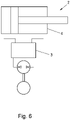
- a differential cylinder is in the 6 shown.
- the left side of the differential cylinder includes a larger area to be pressurized than the right side of the differential cylinder includes the cylinder rod.
- there are different volume flows for actuating the differential cylinder or a larger volume flow is required to activate the differential cylinder to actuate as volume is released into the hydraulic system via the right side.
- less volume flow is required to actuate the differential cylinder on the right-hand side than is delivered to the hydraulic system via the left-hand side.
- This difference in volume flow is provided by a hydraulic accumulator, for example an expansion tank.
- This hydraulic accumulator is preferably preloaded with an adjustable pressure.
- the size of the accumulator and thus of the hydraulic system are reduced and the costs for the hydraulic system are lowered.
- the overall hydraulic system can be made more compact.
- the electrohydrostatic drive includes a first receiving unit with an electromechanical drive and a second receiving unit with a pump unit.
- the shaft sealing ring is arranged between the electromechanical drive and the pump unit, so that the first receiving unit and the second receiving unit are fluidly connected by the shaft sealing ring along the rotating drive shaft.
- the shaft sealing ring seals the first receiving unit against the ingress of mineral oil in relation to the second receiving unit up to a pressure of 10 bar at a design-related speed. Once a design-related maximum speed has been reached, the pressure must be reduced, since the shaft sealing ring can no longer guarantee sealing if the pressure is too high due to the mechanical load.
- FIG. 2 shows a diagram of the operating range of a shaft seal.
- the ordinate axis of the diagram describes the maximum permissible pressure in the second receiving unit 21 with the pump unit 20.
- the maximum permissible pressure in an electrohydrostatic drive with a shaft sealing ring is 10 bar.
- the abscissa axis of the diagram describes the speed of the drive shaft in revolutions per minute (rpm).
- Four characteristic curves (A, B, C, D) are shown for four electrohydrostatic drives with shaft seals of different sizes (pump delivery volumes 250 cm 3 , 80 cm 3 , 32 cm 3 , 19 cm 3 ).
- the shaft sealing ring has the task of realizing a media separation via the rotating drive shaft between the first receiving unit and the second receiving unit.
- the maximum permissible pressure in the second receiving unit depends on the size of the pump unit (diameter of the drive shaft) and the speed of the drive shaft (relative speed between the drive shaft and the sealing lip). The larger the size of the pump unit, the lower the permissible maximum speed.
- an electrohydrostatic drive with a size of 19 cm 3 the maximum pressure in the second receiving unit is 10 bar up to a speed of approx. 1,900 rpm.
- the maximum permissible pressure drops according to characteristic curve D and is reduced to a value of 4 bar at a speed of 4,500 rpm.
- Increasing the speed also increases the mechanical load acting on the shaft seal ring, for example due to friction.
- the pressure within the second receiving unit must be reduced in order to avoid damaging the seal and thus preventing mineral oil from entering the first receiving unit.
- a housing pressure in a range from 4 to 30 bar, in particular in a range from 10 to 25 bar, preferably 20 bar, can be realized.
- a multiple of the pressure can be provided for certain hydraulic applications than in the case of electrohydrostatic drives with a shaft sealing ring (for example 5-7 times).
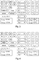
- 3 and 4 show a simulation for accumulator design of an accumulator volume in a hydraulic system.
- the 3 the design of a storage volume in a hydraulic system with an electrohydrostatic drive comprising a shaft seal
- the 4 the design of a storage volume in a hydraulic system with an electrohydrostatic drive comprising a mechanical seal or an electrohydrostatic drive with an applied pressure of 20 bar is simulated.
- the "asp-light" program from Hydac was used to simulate the memory design.
- FIG 5 shows an electrohydrostatic drive 1 with a mechanical seal 30 according to an embodiment of the present invention.
- the basic structure of a mechanical seal 30 is in the enlargement section figure 5 shown.
- the electrohydrostatic drive 1 comprises an electromechanical drive 10 with a rotating drive shaft 12 and a first receiving unit 11, the electromechanical drive 10 being arranged in the first receiving unit 11.
- the electrohydrostatic drive 1 comprises a pump unit 20 and a second receiving unit 21, the pump unit 20 being arranged in the second receiving unit 21 and the second receiving unit 21 containing a transport fluid, for example a mineral oil.
- the first receiving unit 11 and the second receiving unit 21 are arranged in contact with one another, so that the electromechanical drive 10 and the pump unit 20 are connected to one another via the drive shaft 12 .
- the electrohydrostatic drive 1 comprises a mechanical seal 30, the mechanical seal 30 being arranged along the extension direction R of the drive shaft 12 between the electromechanical drive 10 and the pump unit 20 in such a way that the first receiving unit 11 with the electromechanical drive 10 and the second receiving unit 21 are connected to the pump unit 20 by the mechanical seal 30 in a fluid-tight manner with respect to one another along the rotating drive shaft 12 .
- the electrohydrostatic drive 1 is a compact drive in which the electromechanical drive 10 and the pump unit 20 form a closed unit and the mechanical seal 30 serves to separate the media (air - hydraulic fluid) via the rotating Drive shaft 12 to be realized between the first receiving unit 11 and the second receiving unit 21 .
- the mechanical seal 30 comprises a slide ring 31, a slide ring carrier 32, a pressure spring 33 and a counter ring 34, with the pressure spring 33 exerting a counter pressure on the slide ring carrier 32 in such a way that the slide ring 31 by means of the counter pressure provided by the slide ring carrier 32 on the counter ring 34 along the rotating Drive shaft 12 is fluid-tight.
- Static sealing to the first receiving unit 11 or to the second receiving unit 21 takes place via an O-ring 35 to the mating ring 34.
- a driver 36 is mounted on the drive shaft 12 and rotates at the speed of the drive shaft.
- a static O-ring seal takes place on the one hand between the drive shaft 12 and the driver 36 and on the other hand between the driver 36 and slide ring carrier 32.
- the actual sliding ring 31 is pressed against the mating ring 34 by a pressure spring 33 in the sliding ring carrier 32 and implements the dynamic seal between the sliding ring 31 and the mating ring 34.
- the mechanical seal 30 is more complex in terms of the number of individual elements and has larger axial dimensions than the one in FIG 1 shown shaft seal. Due to the larger dimensions of the mechanical seal, the overall length of the electrohydrostatic drive increases in comparison to the embodiment of an electrohydrostatic drive comprising a shaft sealing ring.
- the drive shaft 12 of the electromechanical drive 10 of the electrohydrostatic drive 1 with mechanical seal 30 and the connecting flange between the electromechanical drive 10 and the pump unit 20 are longer to accommodate the mechanical seal 30 along the direction R of the drive shaft 12.
- This also includes a constructional and structural redesign of the first receiving unit 11 and the second receiving unit 21 , which includes a corresponding enlargement and adaptation of the first receiving unit 11 and the second receiving unit 12 .
- the 6 shows an electrohydrostatic drive system 2 comprising at least one electrohydrostatic drive 1 and a control block 3 for controlling an actuator 4.
- the actuator 4 is a hydraulic cylinder, in particular a differential cylinder. Of the Differential cylinder can be connected to a tool.
- the electrohydrostatic drive system 2 also includes a hydraulic accumulator (compensating accumulator) (not shown) to compensate for the pendulum volume.
Landscapes
- Engineering & Computer Science (AREA)
- General Engineering & Computer Science (AREA)
- Mechanical Engineering (AREA)
- Physics & Mathematics (AREA)
- Fluid Mechanics (AREA)
- Details Of Reciprocating Pumps (AREA)
- Details And Applications Of Rotary Liquid Pumps (AREA)
- Actuator (AREA)
Description
- Die vorliegende Erfindung betrifft einen elektrohydrostatischen Antrieb (EPU - Electro Hydrostatic Pump Unit) mit einer Gleitringdichtung.
- Elektrohydrostatische Antriebe sind im Stand der Technik bekannt. Unter einem elektrohydrostatischen Antrieb versteht man die direkte Kopplung eines elektrischen, drehzahlvariablen Antriebs mit einer hydrostatischen Pumpe. Der elektrische Antrieb stellt eine mechanische Antriebsleistung in Form einer Drehzahl und eines Drehmomentes bereit. Die bereitgestellte mechanische Leistung wird von der hydrostatischen Pumpe in eine hydraulische Abtriebsleistung umgesetzt, in Form eines Volumenstroms und eines Betriebsdruckes bzw. einer Druckdifferenz über die Arbeitsanschlüsse der hydrostatischen Pumpe. Der elektrohydrostatische Antrieb ist zudem in der Lage, im Motorbetrieb der hydrostatischen Pumpe eine hydraulische Antriebsleistung in eine mechanische Abtriebsleistung am elektrischen Antrieb zu wandeln. Im elektrohydrostatischen Antrieb erfolgt somit eine Wandlung von elektrischer Leistung in hydraulische Leistung oder Energie und umgekehrt. Für den Energietransport im hydraulischen Teil des Antriebsstrangs des elektrohydrostatischen Antriebs, wird eine Flüssigkeit, in der Regel Hydrauliköl, verwendet. Funktionsbedingt muss eine Trennung der Medien Hydraulikflüssigkeit innerhalb der hydrostatischen Pumpe und Luft innerhalb des elektrischen Antriebs erfolgen. Diese Abdichtung im Stand der Technik bekannten elektrohydrostatischen Antrieben erfolgt dadurch, dass an der Antriebswelle zwischen elektrischem Motor und hydrostatischer Pumpe ein Wellendichtring montiert ist. Die Abdichtung des Wellendichtrings erfolgt auf der nicht rotierenden, statischen Seite über einen Formschluss, beispielsweise im Gehäuse der hydrostatischen Pumpe oder dem elektrischen Antrieb. Eine weitere Abdichtung erfolgt dynamisch zur rotierenden Antriebswelle über eine Dichtlippe. Eine beispielhafte Abdichtung umfassend den Wellendichtring ist in der
Fig. 1 dargestellt. - Einen elektrohydrostatischen Antrieb mit einem solchen Wellendichtring, wie dargestellt in
Fig. 1 , kann in einer speziellen Form bis zu einem maximalen Betriebsdruck bis 10 bar betrieben werden. Bei einer Erhöhung der Drehzahl der Antriebswelle kommt es allerdings in diesem Drehzahlbereich zu einer Reduzierung des maximalen Betriebsdrucks bis auf ca. 4 bar (sieheFig. 2 ). Speziell für den Einsatz von elektrohydrostatischen Antrieben in einer autarken Achse mit integrierten Differentialzylinder ist es vorteilhaft, einen höheren Gehäusedruck über den gesamten Drehzahlbereich zur Verfügung zu haben. - Weiterhin nachteilig bei im Stand der Technik bekannten elektrohydrostatischen Antrieben mit Wellendichtring ist, dass der maximale Arbeitsdruck des Speichers und damit die maximale Druckdifferenz durch den maximalen drehzahlabhängigen Betriebsdruck des Wellendichtrings begrenzt ist. Der Speicher in hydraulischen System übernimmt die Funktion der Vorspannung des hydraulischen Systems und muss den gesamten Pendelvolumenstrom zwischen Kolben- und Stangenseite des Differentialzylinders aufnehmen. Die Größe bzw. das Volumen des Speichers hängt maßgeblich von der Größe des Pendelvolumenstromes zwischen Kolben- und Stangenseite des Differentialzylinders, der dynamischen/thermischen Nutzung (adiabatisch - isotherm) und der zulässigen Druckdifferenz zwischen minimaler und maximaler Füllung des Speichers ab. Somit würde sich das notwendige Speichervolumen bei einer höheren Druckdifferenz zwischen minimaler und maximaler Füllung des Speichers verringern. Durch die Begrenzung des Arbeitsdrucks bei elektrohydrostatischen Antrieben mit Wellendichtring sind entsprechend größer ausgelegte Speicher, mit mehr Fassungsvolumen notwendig, die zu einem funktionell komplexeren und kostenintensiveren Aufbau des Speichers und der Versorgung des hydraulischen Systems führen.
-
DE 10 2006 040130 A1 betrifft eine Förderpumpe mit einem drehzahlvariablen Antrieb und ist als einstufige Kreiselpumpe mit einem in einem Rotorraum eines Pumpengehäuses rotierenden Radialrad zum Fördern eines Fluids zwischen einem Pumpeneinlass und einem Pumpenauslass ausgebildet. Das Radialrad weist Förderkanäle auf und die Kreiselpumpe ist für den Teillastbetrieb ausgelegt. -
DE 10 2014 211 982 A1 betrifft eine Kraftstoffhochdruckpumpe für ein Kraftstoffeinspritzsystem, insbesondere ein Common-Rail-Einspritzsystem, mit einer Antriebswelle, die in einer Lagerbohrung eines Gehäuseteils der Kraftstoffhochdruckpumpe drehbar gelagert ist, und einer Dichtungsanordnung, die zwischen der Antriebswelle und dem Gehäuseteil angeordnet ist. Die Dichtungsanordnung ist als Gleitringdichtung ausgebildet, die einen mit der Antriebswelle drehenden ersten Gleitring und einen mit dem Gehäuseteil verbundenen zweiten Gleitring umfasst, wobei der erste Gleitring über die Federkraft eines Federelements gegen den zweiten Gleitring axial vorgespannt ist. -
DE 12 58 692 B betrifft ein elektrohydraulisches Hubgerät mit einer von einem Elektromotor angetriebenen hydrostatischen Pumpe und einem von der Druckflüssigkeit dieser Pumpe gespeisten Hubzylinder von geringem Durchmesser. -
DE 603 04 504 T2 betrifft eine Gleitringdichtungsvorrichtung umfassend eine Napfdichtung, die aus einem elastischen Gummimaterial zwischen einer Montagefläche des Dichtungsrings und einer Stufenschulter-Installationsfläche hergestellt ist, wobei die Napfdichtung eine Stützplatte in einer integralen Weise hält und eine Stützfläche der Stützplatte in Bezug auf die Montagefläche des Dichtungsrings entgegengesetzt und im Wesentlichen parallel zu dieser weist. -
DE 10 2016 113 882 A1 betrifft ein elektrohydrostatisches System mit einer von einem Elektromotor angetriebenen hydraulischen Maschine, die ein variables Volumen und/oder eine variable Drehzahl zur Bereitstellung eines Volumenstroms einer Hydraulikflüssigkeit aufweist, einem Differentialzylinder mit einer Kolbenfläche und mit einer Ringfläche und mindestens einem Ausgleichsbehälter. Das Antriebssystem hat einen geschlossenen hydraulischen Kreislauf und einen Überdruck gegenüber der Umgebung während des Betriebs mittels der hydraulischen Maschine und/oder einer Vorspannquelle. Das Antriebssystem sorgt für eine Bewegung des Zylinders in einer ersten Richtung mittels eines Volumenstroms der hydraulischen Maschine und eines Volumenstroms aus dem Ausgleichsbehälter und eine Bewegung in einer zweiten Richtung mittels eines Volumenstroms der hydraulischen Maschine und eines Volumenstroms in den Ausgleichsbehälter. - Ausgehend von diesem Stand der Technik, ist es die Aufgabe der vorliegenden Erfindung, die Nachteile des Standes der Technik wenigstens teilweise zu überwinden, bzw. den Stand der Technik zu verbessern.
- Diese Aufgabe wird gemäß einem ersten Aspekt der vorliegenden Erfindung durch einen elektrohydrostatischen Antrieb mit den in Patentanspruch 1 angegebenen Merkmalen gelöst. Bevorzugte Ausführungsformen und Abwandlungen sind Gegenstand der Unteransprüche.
- Die Erfindung schafft gemäß einem ersten Aspekt einen elektrohydrostatischen Antrieb umfassend einen elektromechanischen Antrieb mit einer rotierenden Antriebswelle und einer ersten Aufnahmeeinheit, wobei der elektromechanische Antrieb in der ersten Aufnahmeeinheit angeordnet ist.
- Der elektromechanische Antrieb umfasst weiterhin eine hydrostatische Pumpe und eine zweite Aufnahmeeinheit, wobei die hydrostatische Pumpe in der zweiten Aufnahmeeinheit angeordnet ist und die zweite Aufnahmeeinheit ein Transportfluid enthält.
- Ferner sind die erste Aufnahmeeinheit und die zweite Aufnahmeeinheit zueinander in Kontakt stehend angeordnet, so dass der elektromechanische Antrieb und die hydrostatische Pumpe über die Antriebswelle miteinander verbunden sind.
- Der elektromechanische Antrieb umfasster weiterhin eine Gleitringdichtung, wobei die Gleitringdichtung entlang der Erstreckungsrichtung der Antriebswelle, zwischen dem elektromechanischen Antrieb und der hydrostatische Pumpe derart angeordnet ist, dass die erste Aufnahmeeinheit mit dem elektromechanischen Antrieb und die zweite Aufnahmeeinheit mit der hydrostatische Pumpe durch die Gleitringdichtung gegeneinander fluiddichtend entlang der rotierenden Antriebswelle verbunden sind.
- Elektrohydrostatische Antriebe zeichnen sich durch ihre kompakte Bauweise aus und sind drehzahlregelbar. Die erste Aufnahmeeinheit stellt den Bauraum zur Aufnahme des elektromechanischen Antriebs dar und umfasst zusätzlich als füllendes Medium Luft. Die zweite Aufnahmeeinheit stellt den Bauraum zur Aufnahme der Pumpeneinheit dar und ist zusätzlich mit einem Transportfluid, vorzugsweise mit einem hydraulischen Mineralöl gefüllt. Zwischen der ersten Aufnahmeeinheit und der zweiten Aufnahmeeinheit ist vorzugsweise ein dritter Bauraum ausgebildet, in dem die Gleitringdichtung entlang der Erstreckungsrichtung der Antriebswelle angeordnet ist, die die erste Aufnahmeeinheit und die zweite Aufnahmeeinheit gegeneinander fluiddichtend verbindet.
- In einer Ausführungsform umfasst die Gleitringdichtung einen Gleitring, einen Gleitringträger, eine Anpressfeder und einen Gegenring, wobei die Anpressfeder einen Gegendruck auf den Gleitringträger derart ausübt, dass der Gleitring mittels dem über den Gleitringträger bereitgestellten Gegendruck an dem Gegenring entlang der rotierenden Antriebsache fluiddicht anliegt.
- In einer Ausführungsform umfasst die hydrostatische Pumpe eine Buchse zur verspannenden Aufnahme der Antriebswelle.
- In einer Ausführungsform umfasst die hydrostatische Pumpe einen Gehäuseinnendruck in einem Bereich von 4 bis 30 bar, insbesondere in einem Bereich von 10 bis 25 bar, vorzugsweise von 20 bar.
- Die Erfindung schafft ferner gemäß einem weiteren Aspekt ein elektrohydrostatisches Antriebssystem mit den in Patentanspruch 6 angegebenen Merkmalen.
- Die Erfindung schafft gemäß einem zweiten Aspekt ein elektrohydrostatisches Antriebssystem umfassend wenigstens einen elektrohydrostatischen Antrieb gemäß einem der Patentansprüche 1 bis 5 und einen Steuerblock für das Ansteuern eines Aktuators. Bevorzugte Ausführungsformen und Abwandlungen sind Gegenstand der Unteransprüche.
- In einer Ausführungsform ist der Aktuator ein hydraulischer Zylinder, insbesondere ein Differentialzylinder.
- Gemäß einem weiteren Aspekt der vorliegenden Erfindung kann das elektrohydrostatische Antriebssystem gemäß dem zweiten Aspekt der vorliegenden Erfindung für den Antrieb eines Eilgangs und/oder Kraftgangs eines hydraulischen Zylinders und/oder einer Pressanordnung, wie zum Beispiel einer Strangpresse oder einer Tiefziehpresse verwendet werden.
- Der vorliegenden Erfindung liegt die Kenntnis zugrunde, dass elektrohydrostatische Antriebe mit einer Gleitringdichtung bei einer bauartbedingten maximalen Drehzahl einen höheren Druck für hydraulische Anwendungen, beispielsweise zum Antrieb eines Differentialzylinders, bereitstellen können, bevor ein Verschleiß und/oder ein Verlust der Dichtwirkung der Dichtung eintritt. Bei Leckage und einem Übertritt des Mineralöls in die erste Aufnahmeeinheit mit dem elektromechanischen Antrieb, hätte dies die Zerstörung des elektromechanischen Antriebs zur Folge.
- In vorteilhafterweise Weise kann das 5-7fache des Druckes eines elektrohydrostatischen Antriebs mit einem Wellendichtring durch einen elektrohydrostatischen Antrieb mit Gleitringdichtung abgerufen werden. Somit werden das Einsatzfeld und der Anwendungsumfang des elektrohydrostatischen Antriebs erhöht.
- Eine Beschädigung bzw. Zerstörung der Dichtung wird in vorteilhafter Weise vermieden, da eine Gleitringdichtung robuster gegen mechanische Belastung ist, insbesondere im Kontaktbereich von dynamischen und statischen Bauteilen.
- Zudem ist vorteilhaft, dass eine Gleitringdichtung bei Sonderflüssigkeiten eingesetzt werden kann und somit abdichtend bei chemischen Flüssigkeiten sind.
- In vorteilhafter Weise kann ein hydraulischer Aktuator, beispielsweise ein Differentialzylinder bei verringertem Speichervolumen betrieben werden. Ein Differentialzylinder umfasst bauartbedingt zwei mit Druck beaufschlagbare Flächen unterschiedlicher Größe. Ein Differentialzylinder ist in der
Fig. 6 dargestellt. Die linke Seite des Differentialzylinders umfasst eine größere mit Druck zu beaufschlagende Fläche als die rechte Seite des Differentialzylinders umfassend die Zylinderstange. Diesbezüglich ergeben sich unterschiedliche Volumenströme zur Betätigung des Differentialzylinders, bzw. wird ein größererVolumenstrom benötigt, um den Differentialzylinder zu betätigen, als Volumen über die rechte Seite in das hydraulische System abgegeben wird. Zudem wird weniger Volumenstrom zum Betätigen des Differentialzylinders an der rechten Seite benötigt, als über die linke Seite an das hydraulische System abgegeben wird. Diese Differenz von Volumenstrom wird durch einen hydraulischen Speicher, beispielsweise einen Ausgleichsbehälter, bereitgestellt. Dieser hydraulische Speicher ist vorzugsweise mit einem einstellbaren Druck vorgespannt. Je größer der Unterschied an Fläche ist, umso mehrVolumen und mehr Speicher muss bereitgestellt werden, um einen Ausgleich zu realisieren. Mit einem höheren Druck im System, bereitgestellt durch den elektrohydrostatischen Antrieb, kann der zum Vorspannen notwendige Speicher, wie dargestellt in denFig. 3 und Fig. 4 in vorteilhafter Weise reduziert werden. Die Baugröße des Speichers und somit des hydraulischen Systems werden reduziert und Kosten für das hydraulische System gesenkt. Zudem kann das hydraulische Gesamtsystem kompakter ausgestaltet werden. - Die Erfindung wird nachfolgend anhand verschiedener Ausführungsformen erläutert, wobei darauf hingewiesen wird, dass durch dieses Beispiel Abwandlungen beziehungsweise Ergänzungen, wie sie sich für den Fachmann unmittelbar ergeben, mit umfasst sind. Darüber hinaus stellt dieses bevorzugte Ausführungsbeispiel keine Beschränkung der Erfindung in der Art dar, dass Abwandlungen und Ergänzungen im Umfang der vorliegenden Erfindung liegen.
- Dabei zeigen:
- Fig. 1
- einen elektrohydrostatischen Antrieb mit einem Wellendichtring;
- Fig. 2
- ein Diagramm des Betriebsbereichs eines Wellendichtrings;
- Fig. 3
- den Bedarf an Speichergröße des Speichers bei der Verwendung eines Wellendichtrings;
- Fig. 4
- den Bedarf an Speichergröße des Speichers bei der Verwendung einer Gleitringdichtung;
- Fig. 5
- einen elektrohydrostatischen Antrieb mit einer Gleitringdichtung gemäß einer Ausführungsform der vorliegenden Erfindung;
- Fig. 6
- ein elektrohydrostatisches Antriebssystem mit einem elektrohydrostatischen Antrieb gemäß einer Ausführungsform der vorliegenden Erfindung.
-
Fig. 1 zeigt einen elektrohydrostatischen Antrieb mit einem im Stand der Technik bekannten Wellendichtring. Der elektrohydrostatische Antrieb umfasst eine erste Aufnahmeeinheit mit einem elektromechanischen Antrieb und eine zweite Aufnahmeeinheit mit einer Pumpeneinheit. Der Wellendichtring ist zwischen dem elektromechanischen Antrieb und der Pumpeneinheit angeordnet, so dass die erste Aufnahmeeinheit und die zweite Aufnahmeeinheit durch den Wellendichtring fluiddichtend entlang der rotierenden Antriebswelle verbunden sind. Der Wellendichtring dichtet die erste Aufnahmeeinheit gegen Eintritt von Mineralöl gegenüber der zweiten Aufnahmeeinheit bis zu einem Druck von 10bar bei einer bauartbedingten Drehzahl ab. Ab dem Erreichen einer bauartbedingten maximalen Drehzahl muss der Druck reduziert werden, da der Wellendichtring durch die mechanische Belastung ein Abdichten bei zu hohem Druck nicht mehr gewährleistet. -
Fig. 2 zeigt ein Diagramm des Betriebsbereichs eines Wellendichtrings. Die Ordinatenachse des Diagramms beschreibt den zulässigen maximalen Druck in der zweiten Aufnahmeeinheit 21 mit der Pumpeneinheit 20. Der maximal zulässige Druck in einem elektrohydrostatischen Antrieb mit Wellendichtring beträgt 10 bar. Die Abszissenachse des Diagramms beschreibt die Drehzahl der Antriebswelle in Umdrehung pro Minute (U/min). In dem Diagramm derFig. 2 sind vier Kennlinien (A, B, C, D) für vier elektrohydrostatische Antriebe mit Wellendichtring in unterschiedlicher Baugröße (Pumpenfördervolumina 250cm3, 80cm3, 32cm3, 19cm3) dargestellt. - Der Wellendichtring hat die Aufgabe, eine Medientrennung über die rotierende Antriebswelle zwischen der ersten Aufnahmeeinheit und der zweiten Aufnahmeeinheit zu realisieren. Der zulässige maximale Druck in der zweiten Aufnahmeeinheit ist abhängig von der Baugröße der Pumpeneinheit (Durchmesser der Antriebswelle) und der Drehzahl der Antriebswelle (Relativgeschwindigkeit zwischen Antriebswelle und Dichtlippe). Je größer die Baugröße der Pumpeneinheit, umso geringer ist die zulässige maximale Drehzahl.
- Für beispielsweise einen elektrohydrostatischen Antrieb mit der Baugröße von 19 cm3 (EPU019) beträgt der maximale Druck in der zweiten Aufnahmeeinheit bis zu einer Drehzahl von ca. 1.900 U/min 10 bar. Bei einer weiteren Erhöhung der Drehzahl fällt der maximal zulässige Druck entsprechend der Kennlinie D ab und reduziert sich bei einer Drehzahl von 4.500 U/min auf einen Wert von 4 bar. Durch die Erhöhung der Drehzahl erhöht sich auch die auf den Wellendichtring einwirkende mechanische Belastung, beispielsweise durch Reibung. Somit muss der Druck innerhalb der zweiten Aufnahmeeinheit gesenkt werden, um eine Beschädigung der Dichtung und somit Eintritt von Mineralöl in die erste Aufnahmeeinheit zu vermeiden. Speziell für den Einsatz eines elektrohydrostatischen Antriebs in einer autarken mit einem integrierten Differentialzylinder ist es jedoch wünschenswert, einen höheren Gehäusedruck über den gesamten Drehzahlbereich zur Verfügung zu haben. In vorteilhafter Weise kann bei einem elektrohydrostatischen Antrieb mit einer Gleitringdichtung ein Gehäusedruck in einem Bereich von 4 bis 30 bar, insbesondere in einem Bereich von 10 bis 25 bar, vorzugsweise von 20 bar realisiert werden. Somit kann bei bauartbedingter maximaler Drehzahl, beispielsweise 4500 U/min, ein Vielfaches des Drucks, als bei elektrohydrostatischen Antrieben mit einem Wellendichtring (beispielsweise 5-7fache), für bestimmte hydraulische Anwendungen bereitgestellt werden.
-
Fig. 3 und Fig. 4 zeigen eine Simulation zur Speicherauslegung eines Speichervolumens in einem hydraulischen System. Insbesondere zeigt dieFig. 3 die Auslegung eines Speichervolumens in einem hydraulischen System mit einem elektrohydrostatischen Antrieb umfassend einen Wellendichtring und dieFig. 4 die Auslegung eines Speichervolumens in einem hydraulischen System mit einem elektrohydrostatischen Antrieb umfassend eine Gleitringdichtung bzw. wird ein elektrohydrostatischer Antrieb mit einem anliegenden Druck von 20bar simuliert. Für die Simulation der Speicherauslegung wurde das Programm "asp-light" der Firma Hydac eingesetzt. Bei dem Einsatz eines Differentialzylinders mit den Abmaßen: Kolbendurchmesser = 203,2mm, Stangendurchmesser=88,9mm, Hub=1.238,3mm mit einem elektrohydrostatischen Antrieb, ergibt sich beim Einsatz eines Wellendichtrings zur Abdichtung ein notwendiges Speichervolumen (Gas: N2, p2 = 4 bar, p1 = 2 bar, adiabatisch, Tmin = 10°C, Tmax = 40°C, To = 20°C) von 35l. - Bei der Erhöhung des Druckes p2, dargestellt in
Fig. 4 , auf 20 bar ergibt sich eine notwendige Speichergröße von 21,5l und somit eine Differenz im Speichervolumen in einem Bereich von 12,8l bis 13,2l. Das führt in vorteilhafter Weise zu einem kleineren notwendigen Speicher und damit geringerem Einbauraum. Ferner kann es zu einer Kosteneinsparung im hydraulischen Gesamtsystem führen. Weiterhin vorteilhaft ist, dass elektrohydrostatische Antriebe mit einer Gleitringdichtung in hydraulischen Systemen eingesetzt werden können, die eine kompakte Bauweise der Antriebe aufgrund Mangels an verfügbarem Platz voraussetzen und dennoch für bestimmte Funktionen einen entsprechend hohen Druck benötigen. Dies ergibt sich daraus, das die dezentrale, autarke Achse noch kompakter durch den kleiner auszulegenden Speicher, ausgeführt werden kann. -
Fig. 5 zeigt einen elektrohydrostatischen Antrieb 1 mit einer Gleitringdichtung 30 gemäß einer Ausführungsform der vorliegenden Erfindung. Der prinzipielle Aufbau einer Gleitringdichtung 30 ist im Vergrößerungsabschnitt derFig. 5 dargestellt. Der elektrohydrostatischer Antrieb 1 umfasst einen elektromechanischen Antrieb 10 mit einer rotierenden Antriebswelle 12 und einer ersten Aufnahmeeinheit 11, wobei der elektromechanische Antrieb 10 in der ersten Aufnahmeeinheit 11 angeordnet ist. Ferner umfasst der elektrohydrostatische Antrieb 1 eine Pumpeneinheit 20 und eine zweite Aufnahmeeinheit 21, wobei die Pumpeneinheit 20 in der zweiten Aufnahmeeinheit 21 angeordnet ist und die zweite Aufnahmeeinheit 21 ein Transportfluid, beispielsweise ein Mineralöl enthält. Die erste Aufnahmeeinheit 11 und die zweite Aufnahmeeinheit 21 sind zueinander in Kontakt stehend angeordnet, so dass der elektromechanische Antrieb 10 und die Pumpeneinheit 20 über die Antriebswelle 12 miteinander verbunden sind. Ferner umfasst der elektrohydrostatische Antrieb 1 eine Gleitringdichtung 30, wobei die Gleitringdichtung 30 entlang der Erstreckungsrichtung R der Antriebswelle 12, zwischen dem elektromechanischen Antrieb 10 und der Pumpeneinheit 20 derart angeordnet ist, dass die erste Aufnahmeeinheit 11 mit dem elektromechanischen Antrieb 10 und die zweite Aufnahmeeinheit 21 mit der Pumpeneinheit 20 durch die Gleitringdichtung 30 gegeneinander fluiddichtend entlang der rotierenden Antriebswelle 12 verbunden sind. - Der elektrohydrostatische Antrieb 1 ist ein Kompaktantrieb bei dem der elektromechanische Antrieb 10 und die Pumpeneinheit 20 eine geschlossene Einheit bilden und die Gleitringdichtung 30 dazu dient, eine Medientrennung (Luft - Hydraulikflüssigkeit) über die rotierende Antriebswelle 12 zwischen der ersten Aufnahmeeinheit 11 und der zweiten Aufnahmeeinheit 21 zu realisieren.
- Die Gleitringdichtung 30 umfasst einen Gleitring 31, einen Gleitringträger32, eine Anpressfeder 33 und einen Gegenring 34, wobei die Anpressfeder 33 einen Gegendruck auf den Gleitringträger 32 derart ausübt, dass der Gleitring 31 mittels dem über den Gleitringträger32 bereitgestellten Gegendruck an dem Gegenring 34 entlang der rotierenden Antriebsache 12 fluiddicht anliegt. Die statische Abdichtung zur ersten Aufnahmeeinheit 11 oder zur zweiten Aufnahmeeinheit 21 erfolgt über einen O-Ring35 zum Gegenring 34. Auf der Antriebswelle 12 ist ein Mitnehmer36 montiert, der mit der Drehzahl der Antriebswelle rotiert. Eine statische O-Ring Abdichtung erfolgt zum einen zwischen der Antriebswelle 12 und dem Mitnehmer36 und zum anderen zwischen Mitnehmer36 und Gleitringträger32. Der eigentliche Gleitring 31 wird über eine Anpressfeder 33 im Gleitringträger32 gegen den Gegenring 34 gedrückt und realisiert die dynamische Abdichtung zwischen Gleitring 31 und Gegenring 34.
- Die Gleitringdichtung 30 ist in der Anzahl der einzelnen Elemente aufwendiger ausgestaltet und weist baulich und strukturell bedingt größere axiale Abmessungen auf, als wie der in der
Fig. 1 dargestellte Wellendichtring. Durch die größeren Abmessungen der Gleitringdichtung vergrößert sich die Gesamtlänge des elektrohydrostatischen Antriebs im Vergleich zu der Ausführung eines elektrohydrostatischen Antriebs umfassend einen Wellendichtring. Die Antriebswelle 12 des elektromechanischen Antriebs 10 des elektrohydrostatischen Antriebs 1 mit Gleitringdichtung 30 und derVerbindungsflansch zwischen dem elektromechanischen Antrieb 10 und der Pumpeneinheit 20 sind zur Aufnahme der Gleitringdichtung 30 entlang der Erstreckungsrichtung R der Antriebswelle 12 länger ausgeführt. Ferner umfasst dies eine bauliche und strukturelle Umgestaltung der ersten Aufnahmeeinheit 11 und zweiten Aufnahmeeinheit 21, was eine entsprechende Vergrößerung und Anpassung der ersten Aufnahmeeinheit 11 und der zweiten Aufnahmeeinheit 12 umfasst. -
Fig. 6 zeigt ein elektrohydrostatisches Antriebssystem 2 umfassend wenigstens einen elektrohydrostatischen Antrieb 1 und einen Steuerblock 3 für das Ansteuern eines Aktuators 4. Der Aktuator 4 ist ein hydraulischer Zylinder, insbesondere ein Differentialzylinder. Der Differentialzylinder kann mit einem Werkzeug verbunden sein. Das elektrohydrostatische Antriebssystem 2 umfasst ferner einen Hydrospeicher (Ausgleichsspeicher) (nicht dargestellt) zum Ausgleich des Pendelvolumens. -
- 1
- elektrohydrostatischer Antrieb
- 2
- elektrohydrostatisches Antriebssystem
- 3
- Steuerblock
- 4
- Aktuator
- 10
- elektromechanischer Antrieb
- 11
- erste Aufnahmeeinheit
- 12
- Antriebswelle
- 20
- Pumpeneinheit
- 21
- zweite Aufnahmeeinheit
- 22
- Buchse
- 30
- Gleitringdichtung
- 31
- Gleitring
- 32
- Gleitringträger
- 33
- Anpressfeder
- 34
- Gegenring
- 35
- O-Ring
- 36
- Mitnehmer
- A-D
- Drehzahlkennlinien
Claims (7)
- Elektrohydrostatischer Antrieb (1) umfassend:einen elektromechanischen Antrieb (10) mit einer rotierenden Antriebswelle (12) und einer ersten Aufnahmeeinheit (11), wobei der elektromechanische Antrieb (10) in der ersten Aufnahmeeinheit (11) angeordnet ist;eine hydrostatische Pumpe (20) und eine zweite Aufnahmeeinheit (21), wobei die hydrostatische Pumpe (20) in der zweiten Aufnahmeeinheit (21) angeordnet ist und die zweite Aufnahmeeinheit (21) ein Transportfluid enthält, unddie erste Aufnahmeeinheit (11) und die zweite Aufnahmeeinheit (21) zueinander in Kontakt stehend angeordnet sind, so dass der elektromechanische Antrieb (10) und die hydrostatische Pumpe (20) über die Antriebswelle (12) miteinander verbunden sind,dadurch gekennzeichnet, dassder elektrohydrostatische Antrieb (1) ferner eine Gleitringdichtung (30) umfasst, wobei die Gleitringdichtung (30) entlang der Erstreckungsrichtung (R) der Antriebswelle (12), zwischen dem elektromechanischen Antrieb (10) und der hydrostatischen Pumpe (20) derart angeordnet ist, dass die erste Aufnahmeeinheit (11) mit dem elektromechanischen Antrieb (10) und die zweite Aufnahmeeinheit (21) mit der hydrostatischen Pumpe (20) durch die Gleitringdichtung (30) gegeneinander fluiddicht wenigstens entlang der rotierenden Antriebswelle (12) verbunden sind.
- Elektrohydrostatischer Antrieb (1) gemäß Anspruch 1, wobei die Gleitringdichtung (30) einen Gleitring (31), einen Gleitringträger (32), eine Anpressfeder (33) und einen Gegenring (34) umfasst, wobei die Anpressfeder (33) einen Gegendruck auf den Gleitringträger (32) derart ausübt, dass der Gleitring (31) mittels dem über den Gleitringträger (32) bereitgestellten Gegendruck an dem Gegenring (34) entlang der rotierenden Antriebsache (12) fluiddicht anliegt.
- Elektrohydrostatischer Antrieb (1) gemäß einem der vorhergehenden Ansprüche 1 bis 2, wobei die hydrostatische Pumpe (20) eine Buchse (22) zur verspannenden Aufnahme der Antriebswelle (12) umfasst.
- Elektrohydrostatischer Antrieb (1) gemäß einem der vorhergehenden Ansprüche 1 bis 3, wobei die hydrostatische Pumpe (20) einen Gehäuseinnendruck in einem Bereich von 4 bis 30 bar, insbesondere in einem Bereich von 10 bis 25 bar, vorzugsweise von 20 bar umfasst.
- Elektrohydrostatisches Antriebssystem (2) umfassend wenigstens einen elektrohydrostatischen Antrieb (1) gemäß einem der vorhergehenden Ansprüche 1 bis 4 und einen Steuerblock (3) für das Ansteuern eines Aktuators (4).
- Elektrohydrostatisches Antriebssystem (2) gemäß Anspruch 5, wobei der Aktuator (4) ein hydraulischer Zylinder, insbesondere ein Differentialzylinder ist.
- Verwendung eines elektrohydrostatischen Antriebssystems (2) gemäß Anspruch 6 für den Antrieb eines Eilgangs und/oder Kraftgangs eines hydraulischen Zylinders und/oder einer Pressanordnung, wie zum Beispiel einer Strangpresse oder einer Tiefziehpresse.
Applications Claiming Priority (2)
| Application Number | Priority Date | Filing Date | Title |
|---|---|---|---|
| DE102018126395.3A DE102018126395A1 (de) | 2018-10-23 | 2018-10-23 | Elektrohydrostatischer Antrieb mit vergrößertem Betriebsbereich |
| PCT/EP2019/078721 WO2020083907A1 (de) | 2018-10-23 | 2019-10-22 | ELEKTROHYDROSTATISCHER ANTRIEB MIT VERGRÖßERTEM BETRIEBSBEREICH |
Publications (2)
| Publication Number | Publication Date |
|---|---|
| EP3870853A1 EP3870853A1 (de) | 2021-09-01 |
| EP3870853B1 true EP3870853B1 (de) | 2022-09-07 |
Family
ID=68387300
Family Applications (1)
| Application Number | Title | Priority Date | Filing Date |
|---|---|---|---|
| EP19795145.2A Not-in-force EP3870853B1 (de) | 2018-10-23 | 2019-10-22 | Elektrohydrostatischer antrieb mit vergrössertem betriebsbereich |
Country Status (5)
| Country | Link |
|---|---|
| US (1) | US20210388826A1 (de) |
| EP (1) | EP3870853B1 (de) |
| CN (1) | CN112955654A (de) |
| DE (1) | DE102018126395A1 (de) |
| WO (1) | WO2020083907A1 (de) |
Family Cites Families (12)
| Publication number | Priority date | Publication date | Assignee | Title |
|---|---|---|---|---|
| US2951719A (en) * | 1958-01-27 | 1960-09-06 | Flexibox Ltd | Mechanical seals |
| DE1258692B (de) * | 1963-04-11 | 1968-01-11 | Klose Kommanditgesellschaft | Elektrohydraulisches Hubgeraet |
| US4611529A (en) * | 1984-07-12 | 1986-09-16 | Vickers, Incorporated | Axial piston machine constructed in a removable cartridge form to facilitate assembly and disassembly |
| JP4180832B2 (ja) * | 2002-04-24 | 2008-11-12 | イーグル工業株式会社 | メカニカルシール装置 |
| ITMO20040306A1 (it) * | 2004-11-19 | 2005-02-19 | Lavorwash Spa | Pomapa e apparato di pulizia comprendente tale pompa. |
| DE102006040130A1 (de) * | 2006-08-26 | 2008-02-28 | Ksb Aktiengesellschaft | Förderpumpe |
| JP5834517B2 (ja) * | 2011-06-15 | 2015-12-24 | 宇部興産機械株式会社 | 押出プレス |
| CN202370943U (zh) * | 2011-12-21 | 2012-08-08 | 卡特彼勒公司 | 液压系统的密封装置及具有该密封装置的机器 |
| DE102014211982A1 (de) * | 2014-06-23 | 2015-12-24 | Robert Bosch Gmbh | Kraftstoffhochdruckpumpe für ein Kraftstoffeinspritzsystem |
| DE102014212183A1 (de) * | 2014-06-25 | 2015-12-31 | Robert Bosch Gmbh | Schrägscheibenmaschine |
| DE102016113882A1 (de) * | 2016-07-27 | 2018-02-01 | Moog Gmbh | Elektro-hydrostatisches Antriebssystem |
| WO2018115417A1 (de) * | 2016-12-23 | 2018-06-28 | Grundfos Holding A/S | Kreiselpumpe |
-
2018
- 2018-10-23 DE DE102018126395.3A patent/DE102018126395A1/de not_active Ceased
-
2019
- 2019-10-22 CN CN201980069478.0A patent/CN112955654A/zh active Pending
- 2019-10-22 EP EP19795145.2A patent/EP3870853B1/de not_active Not-in-force
- 2019-10-22 WO PCT/EP2019/078721 patent/WO2020083907A1/de not_active Ceased
- 2019-10-22 US US17/287,454 patent/US20210388826A1/en not_active Abandoned
Also Published As
| Publication number | Publication date |
|---|---|
| WO2020083907A1 (de) | 2020-04-30 |
| CN112955654A (zh) | 2021-06-11 |
| US20210388826A1 (en) | 2021-12-16 |
| EP3870853A1 (de) | 2021-09-01 |
| DE102018126395A1 (de) | 2020-04-23 |
Similar Documents
| Publication | Publication Date | Title |
|---|---|---|
| DE69901841T2 (de) | Stufenlos regelbares keilriemengetriebe und steuerungssystem | |
| DE102012102978B4 (de) | Geschlossener hydraulischer Kreislauf | |
| EP3491253A1 (de) | Elektro-hydrostatisches antriebssystem | |
| WO2008074397A1 (de) | Torsionsschwingungsdämpferanordnung | |
| DE102008062483A1 (de) | Axialkolbenmaschine mit Pulsationsminderung | |
| DE10320053A1 (de) | Dämpferelement für ein Fahrwerk und Verfahren zum Betreiben eines Dämpferelements | |
| DE102012208687A1 (de) | Hydrauliksystem für ein Kraftfahrzeug | |
| DE102007051352A1 (de) | Hydraulische Zahnradmaschine und Verfahren zur Ansteuerung einer hydraulischen Zahnradmaschine | |
| DE102010020690A1 (de) | Hydraulisches Antriebssystem | |
| DE102007004069A1 (de) | Radialkolbenmaschine | |
| WO2015197402A1 (de) | Schrägscheibenmaschine | |
| DE102013007668B4 (de) | Hydraulisches Antriebssystem für zwei in etwa parallel angeordnete Zylinder | |
| DE102018126395A1 (de) | Elektrohydrostatischer Antrieb mit vergrößertem Betriebsbereich | |
| DE2824239A1 (de) | Radialkolbenpumpe | |
| DE10130597B4 (de) | Elektrohydraulischer Aktor auf Basis einer reversierbaren Flügelzellenpumpe mit unterlagerter Druckregelung | |
| DE102009015674A1 (de) | Hydraulikaggregat | |
| EP3084212B1 (de) | Fördereinrichtung für ein fluid | |
| DE19942297A1 (de) | Zahnradmaschine | |
| DE102020203809A1 (de) | Getriebe mit mindestens einer hydraulisch betätigbaren Kupplung | |
| DE102017103091B4 (de) | Maschinenpresse | |
| DE102021113665A1 (de) | Hydraulisches Antriebssystem | |
| DE102014201897A1 (de) | Drehschwingungsdämpfer | |
| DE356552C (de) | Hydraulischer Umformer mechanischer Dreharbeit in Arbeit mit Laengsbewegung | |
| DE102005033707A1 (de) | Vereinfachte, innenbeaufschlagte Axialgleitringdichtung für die CO2-Anwendung | |
| DE102012217100A1 (de) | Pumpenanordnung umfassend eine Flügelzellenpumpe |
Legal Events
| Date | Code | Title | Description |
|---|---|---|---|
| STAA | Information on the status of an ep patent application or granted ep patent |
Free format text: STATUS: UNKNOWN |
|
| STAA | Information on the status of an ep patent application or granted ep patent |
Free format text: STATUS: THE INTERNATIONAL PUBLICATION HAS BEEN MADE |
|
| PUAI | Public reference made under article 153(3) epc to a published international application that has entered the european phase |
Free format text: ORIGINAL CODE: 0009012 |
|
| STAA | Information on the status of an ep patent application or granted ep patent |
Free format text: STATUS: REQUEST FOR EXAMINATION WAS MADE |
|
| 17P | Request for examination filed |
Effective date: 20210511 |
|
| AK | Designated contracting states |
Kind code of ref document: A1 Designated state(s): AL AT BE BG CH CY CZ DE DK EE ES FI FR GB GR HR HU IE IS IT LI LT LU LV MC MK MT NL NO PL PT RO RS SE SI SK SM TR |
|
| DAV | Request for validation of the european patent (deleted) | ||
| DAX | Request for extension of the european patent (deleted) | ||
| REG | Reference to a national code |
Ref country code: DE Ref legal event code: R079 Ref document number: 502019005629 Country of ref document: DE Free format text: PREVIOUS MAIN CLASS: F04B0001044800 Ipc: F04B0001040000 |
|
| GRAP | Despatch of communication of intention to grant a patent |
Free format text: ORIGINAL CODE: EPIDOSNIGR1 |
|
| STAA | Information on the status of an ep patent application or granted ep patent |
Free format text: STATUS: GRANT OF PATENT IS INTENDED |
|
| RIC1 | Information provided on ipc code assigned before grant |
Ipc: F04B 1/0448 20200101ALI20220412BHEP Ipc: F16J 15/34 20060101ALI20220412BHEP Ipc: F04B 53/16 20060101ALI20220412BHEP Ipc: F04B 17/03 20060101ALI20220412BHEP Ipc: F04B 1/04 20200101AFI20220412BHEP |
|
| INTG | Intention to grant announced |
Effective date: 20220504 |
|
| GRAS | Grant fee paid |
Free format text: ORIGINAL CODE: EPIDOSNIGR3 |
|
| GRAA | (expected) grant |
Free format text: ORIGINAL CODE: 0009210 |
|
| STAA | Information on the status of an ep patent application or granted ep patent |
Free format text: STATUS: THE PATENT HAS BEEN GRANTED |
|
| AK | Designated contracting states |
Kind code of ref document: B1 Designated state(s): AL AT BE BG CH CY CZ DE DK EE ES FI FR GB GR HR HU IE IS IT LI LT LU LV MC MK MT NL NO PL PT RO RS SE SI SK SM TR |
|
| REG | Reference to a national code |
Ref country code: GB Ref legal event code: FG4D Free format text: NOT ENGLISH |
|
| REG | Reference to a national code |
Ref country code: CH Ref legal event code: EP Ref country code: AT Ref legal event code: REF Ref document number: 1517238 Country of ref document: AT Kind code of ref document: T Effective date: 20220915 |
|
| REG | Reference to a national code |
Ref country code: DE Ref legal event code: R096 Ref document number: 502019005629 Country of ref document: DE |
|
| REG | Reference to a national code |
Ref country code: IE Ref legal event code: FG4D Free format text: LANGUAGE OF EP DOCUMENT: GERMAN |
|
| REG | Reference to a national code |
Ref country code: LT Ref legal event code: MG9D |
|
| REG | Reference to a national code |
Ref country code: NL Ref legal event code: MP Effective date: 20220907 |
|
| PG25 | Lapsed in a contracting state [announced via postgrant information from national office to epo] |
Ref country code: SE Free format text: LAPSE BECAUSE OF FAILURE TO SUBMIT A TRANSLATION OF THE DESCRIPTION OR TO PAY THE FEE WITHIN THE PRESCRIBED TIME-LIMIT Effective date: 20220907 Ref country code: RS Free format text: LAPSE BECAUSE OF FAILURE TO SUBMIT A TRANSLATION OF THE DESCRIPTION OR TO PAY THE FEE WITHIN THE PRESCRIBED TIME-LIMIT Effective date: 20220907 Ref country code: NO Free format text: LAPSE BECAUSE OF FAILURE TO SUBMIT A TRANSLATION OF THE DESCRIPTION OR TO PAY THE FEE WITHIN THE PRESCRIBED TIME-LIMIT Effective date: 20221207 Ref country code: LV Free format text: LAPSE BECAUSE OF FAILURE TO SUBMIT A TRANSLATION OF THE DESCRIPTION OR TO PAY THE FEE WITHIN THE PRESCRIBED TIME-LIMIT Effective date: 20220907 Ref country code: LT Free format text: LAPSE BECAUSE OF FAILURE TO SUBMIT A TRANSLATION OF THE DESCRIPTION OR TO PAY THE FEE WITHIN THE PRESCRIBED TIME-LIMIT Effective date: 20220907 Ref country code: FI Free format text: LAPSE BECAUSE OF FAILURE TO SUBMIT A TRANSLATION OF THE DESCRIPTION OR TO PAY THE FEE WITHIN THE PRESCRIBED TIME-LIMIT Effective date: 20220907 |
|
| PGFP | Annual fee paid to national office [announced via postgrant information from national office to epo] |
Ref country code: DE Payment date: 20221028 Year of fee payment: 4 |
|
| PG25 | Lapsed in a contracting state [announced via postgrant information from national office to epo] |
Ref country code: HR Free format text: LAPSE BECAUSE OF FAILURE TO SUBMIT A TRANSLATION OF THE DESCRIPTION OR TO PAY THE FEE WITHIN THE PRESCRIBED TIME-LIMIT Effective date: 20220907 Ref country code: GR Free format text: LAPSE BECAUSE OF FAILURE TO SUBMIT A TRANSLATION OF THE DESCRIPTION OR TO PAY THE FEE WITHIN THE PRESCRIBED TIME-LIMIT Effective date: 20221208 |
|
| PG25 | Lapsed in a contracting state [announced via postgrant information from national office to epo] |
Ref country code: SM Free format text: LAPSE BECAUSE OF FAILURE TO SUBMIT A TRANSLATION OF THE DESCRIPTION OR TO PAY THE FEE WITHIN THE PRESCRIBED TIME-LIMIT Effective date: 20220907 Ref country code: RO Free format text: LAPSE BECAUSE OF FAILURE TO SUBMIT A TRANSLATION OF THE DESCRIPTION OR TO PAY THE FEE WITHIN THE PRESCRIBED TIME-LIMIT Effective date: 20220907 Ref country code: PT Free format text: LAPSE BECAUSE OF FAILURE TO SUBMIT A TRANSLATION OF THE DESCRIPTION OR TO PAY THE FEE WITHIN THE PRESCRIBED TIME-LIMIT Effective date: 20230109 Ref country code: ES Free format text: LAPSE BECAUSE OF FAILURE TO SUBMIT A TRANSLATION OF THE DESCRIPTION OR TO PAY THE FEE WITHIN THE PRESCRIBED TIME-LIMIT Effective date: 20220907 Ref country code: CZ Free format text: LAPSE BECAUSE OF FAILURE TO SUBMIT A TRANSLATION OF THE DESCRIPTION OR TO PAY THE FEE WITHIN THE PRESCRIBED TIME-LIMIT Effective date: 20220907 |
|
| PG25 | Lapsed in a contracting state [announced via postgrant information from national office to epo] |
Ref country code: SK Free format text: LAPSE BECAUSE OF FAILURE TO SUBMIT A TRANSLATION OF THE DESCRIPTION OR TO PAY THE FEE WITHIN THE PRESCRIBED TIME-LIMIT Effective date: 20220907 Ref country code: PL Free format text: LAPSE BECAUSE OF FAILURE TO SUBMIT A TRANSLATION OF THE DESCRIPTION OR TO PAY THE FEE WITHIN THE PRESCRIBED TIME-LIMIT Effective date: 20220907 Ref country code: IS Free format text: LAPSE BECAUSE OF FAILURE TO SUBMIT A TRANSLATION OF THE DESCRIPTION OR TO PAY THE FEE WITHIN THE PRESCRIBED TIME-LIMIT Effective date: 20230107 Ref country code: EE Free format text: LAPSE BECAUSE OF FAILURE TO SUBMIT A TRANSLATION OF THE DESCRIPTION OR TO PAY THE FEE WITHIN THE PRESCRIBED TIME-LIMIT Effective date: 20220907 |
|
| REG | Reference to a national code |
Ref country code: CH Ref legal event code: PL |
|
| REG | Reference to a national code |
Ref country code: DE Ref legal event code: R097 Ref document number: 502019005629 Country of ref document: DE |
|
| REG | Reference to a national code |
Ref country code: BE Ref legal event code: MM Effective date: 20221031 |
|
| PG25 | Lapsed in a contracting state [announced via postgrant information from national office to epo] |
Ref country code: NL Free format text: LAPSE BECAUSE OF FAILURE TO SUBMIT A TRANSLATION OF THE DESCRIPTION OR TO PAY THE FEE WITHIN THE PRESCRIBED TIME-LIMIT Effective date: 20220907 Ref country code: MC Free format text: LAPSE BECAUSE OF FAILURE TO SUBMIT A TRANSLATION OF THE DESCRIPTION OR TO PAY THE FEE WITHIN THE PRESCRIBED TIME-LIMIT Effective date: 20220907 Ref country code: LU Free format text: LAPSE BECAUSE OF NON-PAYMENT OF DUE FEES Effective date: 20221022 Ref country code: AL Free format text: LAPSE BECAUSE OF FAILURE TO SUBMIT A TRANSLATION OF THE DESCRIPTION OR TO PAY THE FEE WITHIN THE PRESCRIBED TIME-LIMIT Effective date: 20220907 |
|
| PLBE | No opposition filed within time limit |
Free format text: ORIGINAL CODE: 0009261 |
|
| STAA | Information on the status of an ep patent application or granted ep patent |
Free format text: STATUS: NO OPPOSITION FILED WITHIN TIME LIMIT |
|
| PG25 | Lapsed in a contracting state [announced via postgrant information from national office to epo] |
Ref country code: LI Free format text: LAPSE BECAUSE OF NON-PAYMENT OF DUE FEES Effective date: 20221031 Ref country code: DK Free format text: LAPSE BECAUSE OF FAILURE TO SUBMIT A TRANSLATION OF THE DESCRIPTION OR TO PAY THE FEE WITHIN THE PRESCRIBED TIME-LIMIT Effective date: 20220907 Ref country code: CH Free format text: LAPSE BECAUSE OF NON-PAYMENT OF DUE FEES Effective date: 20221031 |
|
| 26N | No opposition filed |
Effective date: 20230608 |
|
| PG25 | Lapsed in a contracting state [announced via postgrant information from national office to epo] |
Ref country code: SI Free format text: LAPSE BECAUSE OF FAILURE TO SUBMIT A TRANSLATION OF THE DESCRIPTION OR TO PAY THE FEE WITHIN THE PRESCRIBED TIME-LIMIT Effective date: 20220907 |
|
| PG25 | Lapsed in a contracting state [announced via postgrant information from national office to epo] |
Ref country code: BE Free format text: LAPSE BECAUSE OF NON-PAYMENT OF DUE FEES Effective date: 20221031 |
|
| PG25 | Lapsed in a contracting state [announced via postgrant information from national office to epo] |
Ref country code: IE Free format text: LAPSE BECAUSE OF NON-PAYMENT OF DUE FEES Effective date: 20221022 |
|
| PG25 | Lapsed in a contracting state [announced via postgrant information from national office to epo] |
Ref country code: FR Free format text: LAPSE BECAUSE OF NON-PAYMENT OF DUE FEES Effective date: 20221107 |
|
| PG25 | Lapsed in a contracting state [announced via postgrant information from national office to epo] |
Ref country code: CY Free format text: LAPSE BECAUSE OF FAILURE TO SUBMIT A TRANSLATION OF THE DESCRIPTION OR TO PAY THE FEE WITHIN THE PRESCRIBED TIME-LIMIT Effective date: 20220907 |
|
| REG | Reference to a national code |
Ref country code: DE Ref legal event code: R119 Ref document number: 502019005629 Country of ref document: DE |
|
| PG25 | Lapsed in a contracting state [announced via postgrant information from national office to epo] |
Ref country code: MK Free format text: LAPSE BECAUSE OF FAILURE TO SUBMIT A TRANSLATION OF THE DESCRIPTION OR TO PAY THE FEE WITHIN THE PRESCRIBED TIME-LIMIT Effective date: 20220907 Ref country code: IT Free format text: LAPSE BECAUSE OF FAILURE TO SUBMIT A TRANSLATION OF THE DESCRIPTION OR TO PAY THE FEE WITHIN THE PRESCRIBED TIME-LIMIT Effective date: 20220907 Ref country code: HU Free format text: LAPSE BECAUSE OF FAILURE TO SUBMIT A TRANSLATION OF THE DESCRIPTION OR TO PAY THE FEE WITHIN THE PRESCRIBED TIME-LIMIT; INVALID AB INITIO Effective date: 20191022 |
|
| GBPC | Gb: european patent ceased through non-payment of renewal fee |
Effective date: 20231022 |
|
| PG25 | Lapsed in a contracting state [announced via postgrant information from national office to epo] |
Ref country code: GB Free format text: LAPSE BECAUSE OF NON-PAYMENT OF DUE FEES Effective date: 20231022 |
|
| PG25 | Lapsed in a contracting state [announced via postgrant information from national office to epo] |
Ref country code: GB Free format text: LAPSE BECAUSE OF NON-PAYMENT OF DUE FEES Effective date: 20231022 Ref country code: DE Free format text: LAPSE BECAUSE OF NON-PAYMENT OF DUE FEES Effective date: 20240501 Ref country code: BG Free format text: LAPSE BECAUSE OF FAILURE TO SUBMIT A TRANSLATION OF THE DESCRIPTION OR TO PAY THE FEE WITHIN THE PRESCRIBED TIME-LIMIT Effective date: 20220907 |
|
| PG25 | Lapsed in a contracting state [announced via postgrant information from national office to epo] |
Ref country code: MT Free format text: LAPSE BECAUSE OF FAILURE TO SUBMIT A TRANSLATION OF THE DESCRIPTION OR TO PAY THE FEE WITHIN THE PRESCRIBED TIME-LIMIT Effective date: 20220907 |
|
| PG25 | Lapsed in a contracting state [announced via postgrant information from national office to epo] |
Ref country code: TR Free format text: LAPSE BECAUSE OF FAILURE TO SUBMIT A TRANSLATION OF THE DESCRIPTION OR TO PAY THE FEE WITHIN THE PRESCRIBED TIME-LIMIT Effective date: 20220907 |
|
| REG | Reference to a national code |
Ref country code: AT Ref legal event code: MM01 Ref document number: 1517238 Country of ref document: AT Kind code of ref document: T Effective date: 20241022 |
|
| PG25 | Lapsed in a contracting state [announced via postgrant information from national office to epo] |
Ref country code: AT Free format text: LAPSE BECAUSE OF NON-PAYMENT OF DUE FEES Effective date: 20241022 |
|
| PGFP | Annual fee paid to national office [announced via postgrant information from national office to epo] |
Ref country code: AT Payment date: 20260410 Year of fee payment: 5 |