EP3869682A1 - Verfahren und steuerungsvorrichtung zur steuerung eines stromwandlers - Google Patents
Verfahren und steuerungsvorrichtung zur steuerung eines stromwandlers Download PDFInfo
- Publication number
- EP3869682A1 EP3869682A1 EP20159044.5A EP20159044A EP3869682A1 EP 3869682 A1 EP3869682 A1 EP 3869682A1 EP 20159044 A EP20159044 A EP 20159044A EP 3869682 A1 EP3869682 A1 EP 3869682A1
- Authority
- EP
- European Patent Office
- Prior art keywords
- value
- power
- frequency
- power converter
- control value
- Prior art date
- Legal status (The legal status is an assumption and is not a legal conclusion. Google has not performed a legal analysis and makes no representation as to the accuracy of the status listed.)
- Granted
Links
Images

Classifications
-
- H—ELECTRICITY
- H02—GENERATION; CONVERSION OR DISTRIBUTION OF ELECTRIC POWER
- H02M—APPARATUS FOR CONVERSION BETWEEN AC AND AC, BETWEEN AC AND DC, OR BETWEEN DC AND DC, AND FOR USE WITH MAINS OR SIMILAR POWER SUPPLY SYSTEMS; CONVERSION OF DC OR AC INPUT POWER INTO SURGE OUTPUT POWER; CONTROL OR REGULATION THEREOF
- H02M1/00—Details of apparatus for conversion
-
- H—ELECTRICITY
- H02—GENERATION; CONVERSION OR DISTRIBUTION OF ELECTRIC POWER
- H02J—ELECTRIC POWER NETWORKS; CIRCUIT ARRANGEMENTS OR SYSTEMS FOR SUPPLYING OR DISTRIBUTING ELECTRIC POWER; SYSTEMS FOR STORING ELECTRIC ENERGY
- H02J4/00—Circuit arrangements for mains or distribution networks not specified as AC or DC; Circuit arrangements for mains or distribution networks combining AC and DC sections or sub-networks
- H02J4/20—Networks integrating separated AC and DC power sections
- H02J4/25—Networks integrating separated AC and DC power sections for transfer of electric power between AC and DC networks, e.g. for supplying the DC section within a load from an AC mains system
-
- H—ELECTRICITY
- H02—GENERATION; CONVERSION OR DISTRIBUTION OF ELECTRIC POWER
- H02M—APPARATUS FOR CONVERSION BETWEEN AC AND AC, BETWEEN AC AND DC, OR BETWEEN DC AND DC, AND FOR USE WITH MAINS OR SIMILAR POWER SUPPLY SYSTEMS; CONVERSION OF DC OR AC INPUT POWER INTO SURGE OUTPUT POWER; CONTROL OR REGULATION THEREOF
- H02M7/00—Conversion of AC power input into DC power output; Conversion of DC power input into AC power output
- H02M7/42—Conversion of DC power input into AC power output without possibility of reversal
- H02M7/44—Conversion of DC power input into AC power output without possibility of reversal by static converters
- H02M7/48—Conversion of DC power input into AC power output without possibility of reversal by static converters using discharge tubes with control electrode or semiconductor devices with control electrode
- H02M7/53—Conversion of DC power input into AC power output without possibility of reversal by static converters using discharge tubes with control electrode or semiconductor devices with control electrode using devices of a triode or transistor type requiring continuous application of a control signal
- H02M7/537—Conversion of DC power input into AC power output without possibility of reversal by static converters using discharge tubes with control electrode or semiconductor devices with control electrode using devices of a triode or transistor type requiring continuous application of a control signal using semiconductor devices only, e.g. single switched pulse inverters
- H02M7/539—Conversion of DC power input into AC power output without possibility of reversal by static converters using discharge tubes with control electrode or semiconductor devices with control electrode using devices of a triode or transistor type requiring continuous application of a control signal using semiconductor devices only, e.g. single switched pulse inverters with automatic control of output wave form or frequency
- H02M7/5395—Conversion of DC power input into AC power output without possibility of reversal by static converters using discharge tubes with control electrode or semiconductor devices with control electrode using devices of a triode or transistor type requiring continuous application of a control signal using semiconductor devices only, e.g. single switched pulse inverters with automatic control of output wave form or frequency by pulse-width modulation
-
- H—ELECTRICITY
- H02—GENERATION; CONVERSION OR DISTRIBUTION OF ELECTRIC POWER
- H02J—ELECTRIC POWER NETWORKS; CIRCUIT ARRANGEMENTS OR SYSTEMS FOR SUPPLYING OR DISTRIBUTING ELECTRIC POWER; SYSTEMS FOR STORING ELECTRIC ENERGY
- H02J3/00—Circuit arrangements for AC mains or AC distribution networks
- H02J3/38—Arrangements for feeding a single network from two or more generators or sources in parallel; Arrangements for feeding already energised networks from additional generators or sources in parallel
-
- G—PHYSICS
- G05—CONTROLLING; REGULATING
- G05B—CONTROL OR REGULATING SYSTEMS IN GENERAL; FUNCTIONAL ELEMENTS OF SUCH SYSTEMS; MONITORING OR TESTING ARRANGEMENTS FOR SUCH SYSTEMS OR ELEMENTS
- G05B6/00—Internal feedback arrangements for obtaining particular characteristics, e.g. proportional, integral or differential
- G05B6/02—Internal feedback arrangements for obtaining particular characteristics, e.g. proportional, integral or differential electric
-
- H—ELECTRICITY
- H02—GENERATION; CONVERSION OR DISTRIBUTION OF ELECTRIC POWER
- H02J—ELECTRIC POWER NETWORKS; CIRCUIT ARRANGEMENTS OR SYSTEMS FOR SUPPLYING OR DISTRIBUTING ELECTRIC POWER; SYSTEMS FOR STORING ELECTRIC ENERGY
- H02J3/00—Circuit arrangements for AC mains or AC distribution networks
- H02J3/001—Arrangements for handling faults or abnormalities, e.g. emergencies or contingencies
- H02J3/0014—Arrangements for handling faults or abnormalities, e.g. emergencies or contingencies for preventing or reducing power oscillations in networks
- H02J3/00142—Oscillations concerning frequency
-
- H—ELECTRICITY
- H02—GENERATION; CONVERSION OR DISTRIBUTION OF ELECTRIC POWER
- H02J—ELECTRIC POWER NETWORKS; CIRCUIT ARRANGEMENTS OR SYSTEMS FOR SUPPLYING OR DISTRIBUTING ELECTRIC POWER; SYSTEMS FOR STORING ELECTRIC ENERGY
- H02J3/00—Circuit arrangements for AC mains or AC distribution networks
- H02J3/04—Arrangements for connecting networks of the same frequency but supplied from different sources
- H02J3/06—Controlling the transfer of power between connected networks; Controlling load sharing between connected networks
-
- H—ELECTRICITY
- H02—GENERATION; CONVERSION OR DISTRIBUTION OF ELECTRIC POWER
- H02J—ELECTRIC POWER NETWORKS; CIRCUIT ARRANGEMENTS OR SYSTEMS FOR SUPPLYING OR DISTRIBUTING ELECTRIC POWER; SYSTEMS FOR STORING ELECTRIC ENERGY
- H02J3/00—Circuit arrangements for AC mains or AC distribution networks
- H02J3/28—Arrangements for balancing of the load in networks by storage of energy
- H02J3/32—Arrangements for balancing of the load in networks by storage of energy using batteries or super capacitors with converting means
-
- H—ELECTRICITY
- H02—GENERATION; CONVERSION OR DISTRIBUTION OF ELECTRIC POWER
- H02J—ELECTRIC POWER NETWORKS; CIRCUIT ARRANGEMENTS OR SYSTEMS FOR SUPPLYING OR DISTRIBUTING ELECTRIC POWER; SYSTEMS FOR STORING ELECTRIC ENERGY
- H02J3/00—Circuit arrangements for AC mains or AC distribution networks
- H02J3/38—Arrangements for feeding a single network from two or more generators or sources in parallel; Arrangements for feeding already energised networks from additional generators or sources in parallel
- H02J3/381—Dispersed generators
-
- H—ELECTRICITY
- H02—GENERATION; CONVERSION OR DISTRIBUTION OF ELECTRIC POWER
- H02J—ELECTRIC POWER NETWORKS; CIRCUIT ARRANGEMENTS OR SYSTEMS FOR SUPPLYING OR DISTRIBUTING ELECTRIC POWER; SYSTEMS FOR STORING ELECTRIC ENERGY
- H02J3/00—Circuit arrangements for AC mains or AC distribution networks
- H02J3/38—Arrangements for feeding a single network from two or more generators or sources in parallel; Arrangements for feeding already energised networks from additional generators or sources in parallel
- H02J3/388—Arrangements for the handling of islanding, e.g. for disconnection or for avoiding the disconnection of power
-
- H—ELECTRICITY
- H02—GENERATION; CONVERSION OR DISTRIBUTION OF ELECTRIC POWER
- H02M—APPARATUS FOR CONVERSION BETWEEN AC AND AC, BETWEEN AC AND DC, OR BETWEEN DC AND DC, AND FOR USE WITH MAINS OR SIMILAR POWER SUPPLY SYSTEMS; CONVERSION OF DC OR AC INPUT POWER INTO SURGE OUTPUT POWER; CONTROL OR REGULATION THEREOF
- H02M1/00—Details of apparatus for conversion
- H02M1/12—Arrangements for reducing harmonics from AC input or output
- H02M1/126—Arrangements for reducing harmonics from AC input or output using passive filters
-
- H—ELECTRICITY
- H02—GENERATION; CONVERSION OR DISTRIBUTION OF ELECTRIC POWER
- H02J—ELECTRIC POWER NETWORKS; CIRCUIT ARRANGEMENTS OR SYSTEMS FOR SUPPLYING OR DISTRIBUTING ELECTRIC POWER; SYSTEMS FOR STORING ELECTRIC ENERGY
- H02J13/00—Circuit arrangements for providing remote monitoring or remote control of equipment in a power distribution network
- H02J13/12—Monitoring network conditions, e.g. electrical magnitudes or operational status
-
- H—ELECTRICITY
- H02—GENERATION; CONVERSION OR DISTRIBUTION OF ELECTRIC POWER
- H02J—ELECTRIC POWER NETWORKS; CIRCUIT ARRANGEMENTS OR SYSTEMS FOR SUPPLYING OR DISTRIBUTING ELECTRIC POWER; SYSTEMS FOR STORING ELECTRIC ENERGY
- H02J2101/00—Supply or distribution of decentralised, dispersed or local electric power generation
- H02J2101/20—Dispersed power generation using renewable energy sources
-
- H—ELECTRICITY
- H02—GENERATION; CONVERSION OR DISTRIBUTION OF ELECTRIC POWER
- H02J—ELECTRIC POWER NETWORKS; CIRCUIT ARRANGEMENTS OR SYSTEMS FOR SUPPLYING OR DISTRIBUTING ELECTRIC POWER; SYSTEMS FOR STORING ELECTRIC ENERGY
- H02J2105/00—Networks for supplying or distributing electric power characterised by their spatial reach or by the load
- H02J2105/10—Local stationary networks having a local or delimited stationary reach
-
- H—ELECTRICITY
- H02—GENERATION; CONVERSION OR DISTRIBUTION OF ELECTRIC POWER
- H02M—APPARATUS FOR CONVERSION BETWEEN AC AND AC, BETWEEN AC AND DC, OR BETWEEN DC AND DC, AND FOR USE WITH MAINS OR SIMILAR POWER SUPPLY SYSTEMS; CONVERSION OF DC OR AC INPUT POWER INTO SURGE OUTPUT POWER; CONTROL OR REGULATION THEREOF
- H02M1/00—Details of apparatus for conversion
- H02M1/0003—Details of control, feedback or regulation circuits
- H02M1/0025—Arrangements for modifying reference values, feedback values or error values in the control loop of a converter
-
- Y—GENERAL TAGGING OF NEW TECHNOLOGICAL DEVELOPMENTS; GENERAL TAGGING OF CROSS-SECTIONAL TECHNOLOGIES SPANNING OVER SEVERAL SECTIONS OF THE IPC; TECHNICAL SUBJECTS COVERED BY FORMER USPC CROSS-REFERENCE ART COLLECTIONS [XRACs] AND DIGESTS
- Y02—TECHNOLOGIES OR APPLICATIONS FOR MITIGATION OR ADAPTATION AGAINST CLIMATE CHANGE
- Y02B—CLIMATE CHANGE MITIGATION TECHNOLOGIES RELATED TO BUILDINGS, e.g. HOUSING, HOUSE APPLIANCES OR RELATED END-USER APPLICATIONS
- Y02B90/00—Enabling technologies or technologies with a potential or indirect contribution to GHG emissions mitigation
- Y02B90/20—Smart grids as enabling technology in buildings sector
-
- Y—GENERAL TAGGING OF NEW TECHNOLOGICAL DEVELOPMENTS; GENERAL TAGGING OF CROSS-SECTIONAL TECHNOLOGIES SPANNING OVER SEVERAL SECTIONS OF THE IPC; TECHNICAL SUBJECTS COVERED BY FORMER USPC CROSS-REFERENCE ART COLLECTIONS [XRACs] AND DIGESTS
- Y04—INFORMATION OR COMMUNICATION TECHNOLOGIES HAVING AN IMPACT ON OTHER TECHNOLOGY AREAS
- Y04S—SYSTEMS INTEGRATING TECHNOLOGIES RELATED TO POWER NETWORK OPERATION, COMMUNICATION OR INFORMATION TECHNOLOGIES FOR IMPROVING THE ELECTRICAL POWER GENERATION, TRANSMISSION, DISTRIBUTION, MANAGEMENT OR USAGE, i.e. SMART GRIDS
- Y04S20/00—Management or operation of end-user stationary applications or the last stages of power distribution; Controlling, monitoring or operating thereof
- Y04S20/12—Energy storage units, uninterruptible power supply [UPS] systems or standby or emergency generators, e.g. in the last power distribution stages
Definitions
- the disclosure relates generally to control of a power converter constituting a part of an alternating current system e.g. a microgrid. More particularly, the disclosure relates to a control device and to a method for controlling a power converter. Furthermore, the disclosure relates to a computer program for controlling a power converter.
- an alternating current "AC" system such as e.g. a microgrid
- a power converter for converting direct voltage into one or more alternating voltages e.g. into three-phase alternating voltage.
- An AC system of the kind mentioned above can be connected in parallel with another AC system that can be for example a utility grid or an AC system supplied with one or more power converters and/or one or more gensets each employing a generator driven by a combustion engine, a wind turbine, a hydro turbine, or some other prime mover.
- a common objective when running an AC system, such as e.g. a microgrid, in parallel with another AC system is to share a load between the AC systems.
- a desired operation can be such that the utility grid feeds all consumed electric power and the microgrid operates in parallel with zero power but is ready to take on load if the utility grid is disconnected.
- a battery can be connected to a direct voltage side of a power converter of a microgrid and the battery is charged when the microgrid is connected to the utility grid. To charge the battery, the power converter draws electric power from the utility grid and feeds that to the battery. In both the above-mentioned example cases, the electric power of the power converter of the microgrid needs to be controlled.
- AFE active front-end
- phase currents of a power converter are controlled using a feedback control.
- Power control can be achieved through the current control.
- the phase voltages are not controlled but the phase voltages assume values that are required to force the phase currents to target values.
- the microgrid control objective which is to generate controlled sinusoidal voltages and let loads determine the currents.
- to employ the AFE control in a microgrid run in parallel with a utility grid means a need to use the AFE control when the utility grid is connected and to switch to voltage control when the utility grid is disconnected and a power converter of the microgrid needs to generate desired sinusoidal voltages.
- the switchover may require stopping of modulation in the power converter of the microgrid. If the utility grid is not connected when the modulation is stopped, the microgrid experiences a black out situation.
- a requirement that the modulation is not stopped means that a switchover process should be carried out in a short time frame, e.g. about 100 microseconds.
- the control mode that is being switched on needs to be initialized so that the voltages smoothly continue when the previous control mode leaves them. This requirement increases complexity and sets considerable requirements to computation resources.
- a new control device for controlling a power converter that can be e.g. a power converter constituting a part of an alternating current "AC" microgrid.
- a control device comprises a data processing system configured to:
- the dependence of the frequency control value on the frequency droop value constitutes a drooping feedback from the electric power of the power converter to the alternating voltage frequency of the power converter.
- Electric power supplied by the power converter to an alternating current "AC" system e.g. a parallel connection of an AC microgrid and an AC utility grid, increases when the alternating voltage frequency of the power converter is greater than operating frequency of the AC system because this frequency difference increases a power angle between the power converter and the AC system.
- the above-mentioned drooping feedback decreases the alternating voltage frequency of the power converter, which in turn reduces the electric power.
- the electric power supplied by the power converter to the AC system decreases when the alternating voltage frequency of the power converter is less than the operating frequency of the AC system because this frequency difference decreases the above-mentioned power angle.
- the above-mentioned drooping feedback increases the alternating voltage frequency of the power converter, which increases the electric power.
- the electric power is driven to a value at which a combined effect of the drooping feedback and the above-mentioned power control value makes the alternating voltage frequency of the power converter to be the same as the operating frequency of the AC system.
- the electric power can be controlled by changing the power control value in order to drive the electric power to its target value. If, for example, the power control value is stepwise increased, the alternating voltage frequency of the power converter gets greater than the operating frequency of the AC system and thus the power angle and thereby the electric power supplied to the AC system start to increase.
- the drooping feedback starts to decrease the alternating voltage frequency of the power converter until the alternating voltage frequency of the power converter gets equal to the operating frequency of the AC system and thereby the power angle stops increasing.
- the end-value of the power angle is greater than its value at a time instant of the stepwise increase of the power control value.
- the electric power is increased by an amount corresponding to the stepwise increase of the power control value.
- the drooping feedback makes it possible for the power converter to adapt to variations of the operating frequency of the AC system.
- the term “electric power” means active power in conjunction with AC systems, i.e. not reactive power nor apparent power.
- the term “electric power” is used because this term is applicable in conjunction with both AC systems and direct current “DC” systems.
- a method according to the invention comprises:
- a computer program according to the invention comprises computer executable instructions for controlling a programmable processing system to:
- the computer program product comprises a non-volatile computer readable medium, e.g. a compact disc "CD”, encoded with a computer program according to the invention.
- a non-volatile computer readable medium e.g. a compact disc "CD”
- FIG. 1a shows a high-level block diagram of a power converter 109 according to an exemplifying and non-limiting embodiment.
- the power converter 109 is configured to transfer electric power between a direct current "DC" system 105 and an alternating current "AC" system 114 via a line filter 106 that can be for example an inductor-capacitor-inductor "LCL” filter.
- the AC system 114 comprises an AC microgrid 107 and another AC grid 108 that can be e.g. an AC utility grid.
- the AC microgrid 107 and the AC grid 108 are parallel connected via a circuit breaker 115.
- the DC system 105 may comprise for example a fuel cell and/or a photovoltaic panel and/or a battery system and/or a capacitor system, where the battery and/or capacitor system is sometimes charged and sometimes discharged.
- the power converter 109 comprises a converter stage 104 configured to convert the direct voltage U DC into alternating voltages.
- the power converter 109 is configured to convert the direct voltage U DC into three-phase alternating voltage. It is however also possible that the number of phases is less than three or greater than three.
- the converter stage 104 can be e.g. an inverter bridge implemented with controllable semiconductor components such as e.g. insulated gate bipolar transistors "IGBT” or gate turn off "GTO" thyristors, and possibly with diodes that are antiparallel with the controllable semiconductor components.
- IGBT insulated gate bipolar transistors
- GTO gate turn off
- the power converter 109 comprises a driver stage 103 configured to control the converter stage 104 to form the three-phase alternating voltage in accordance with a frequency control value f c expressing frequency of the three-phase alternating voltage.
- the driver stage 103 is configured to control the converter stage 104 also in accordance with a voltage control value U c that expresses an amplitude of the three-phase alternating voltage.
- the three-phase alternating voltage can be produced e.g. by forming phase voltage references and running pulse width modulation "PWM" in accordance with the phase voltage references.
- PWM results in phase voltages that constitute the three-phase alternating voltage.
- There are also other techniques to form the three-phase alternating voltage using PWM e.g. space-vector modulation.
- the power converter 109 comprises a control device 101 according to an exemplifying and non-limiting embodiment for determining the above-mentioned frequency control value f c .
- the control device 101 is configured to determine the above-mentioned voltage control value U c , too.
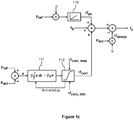
- a signal diagram of the control device 101 is shown in figure 1b .
- the control device 101 comprises a data processing system 102 configured to form a frequency droop value ⁇ f droop based on data indicative of actual electric power p act of the power converter 109.
- the data processing system 102 is configured to change the frequency control value f c by the frequency droop value ⁇ f droop so that the frequency droop value decreases the frequency control value f c when a power flow direction is outwards from alternating voltage terminals 113 of the power converter 109 i.e. the power flow direction is from the power converter 109 to the AC system 114.
- the frequency droop value ⁇ f droop increases the frequency control value f c when the power flow direction is from the AC system 114 to the power converter 109.
- the dependence of the frequency control value f c on the frequency droop value ⁇ f droop constitutes a drooping feedback from the electric power p act of the power converter 109 to the alternating voltage frequency of the power converter 109.
- the electric power p act increases when the alternating voltage frequency of the power converter 109 is greater than operating frequency of the AC system 114 because this frequency difference increases a power angle between the power converter 109 and the AC system 114.
- the above-mentioned drooping feedback decreases the alternating voltage frequency of the power converter 109, which in turn reduces the electric power p act .
- the electric power p act decreases when the alternating voltage frequency of the power converter is less than the operating frequency of the AC system 114 because this frequency difference decreases the above-mentioned power angle.
- the above-mentioned drooping feedback increases the alternating voltage frequency of the power converter 109, which in turn increases the electric power p act .
- the data processing system 102 is configured to form a power control value ⁇ f pc based on data indicative of a target value p ref of the electric power of the power converter 109.
- the data processing system 102 is configured to change the frequency control value f c by the power control value ⁇ f pc so that the power control value increases the frequency control value when the target value p ref corresponds to the power flow direction outwards from the alternating voltage terminals 113 of the power converter i.e. the power flow direction from the power converter 109 to the AC system 114.
- the power control value ⁇ f pc decreases the frequency control value f c when the target value p ref corresponds to the power flow direction from the AC system 114 to the power converter 109.
- the data processing system 102 is configured to deliver the frequency control value f c to the driver stage 103 so as to control the alternating voltage frequency of the power converter 109.
- the electric power p act is driven to a value at which a combined effect of the drooping feedback and the above-mentioned power control value ⁇ f pc makes the alternating voltage frequency of the power converter 109 to be the same as the operating frequency of the AC system 114.
- the electric power p act can be controlled by changing the power control value ⁇ f pc in order to drive the electric power p act to its target value p ref .
- the alternating voltage frequency of the power converter 109 gets greater than the operating frequency of the AC system 114 and thus the power angle and thereby the electric power p act start to increase.
- the drooping feedback starts to decrease the alternating voltage frequency of the power converter 109 until the alternating voltage frequency of the power converter 109 gets equal to the operating frequency of the AC system 114 and thereby the power angle stops increasing.
- the end-value of the power angle is greater than its value at a time instant of the stepwise increase of the power control value.
- the electric power p act is increased by an amount corresponding to the stepwise increment d ⁇ f pc of the power control value.
- the base value f 0 can be set, for example, as close as possible to the operating frequency of the AC system 114.
- the drooping rate coefficient k droop can be for example in the range from 0.01 to 0.1, e.g. 0.04.
- the data processing system 102 is configured to limit a rate of change of the power control value ⁇ f pc i.e. d ⁇ f pc /dt, to be at most a predetermined upper limit.
- the limitation of the rate of change is depicted with a ramping block 110. The limitation of the rate of change can be advantageous for example when the AC microgrid 107 is started from a black-out situation.
- the electric power p act of the power converter 109 is e.g. zero and the electric power supplied by the AC grid 108 to the AC microgrid 107 is the nominal power p nom of the power converter 109.
- the target value p ref is assumed to be zero.
- the operating frequency of the AC grid 108 changes by ⁇ f.
- the change ⁇ f causes a change in the electric power p act of the power converter 109 because the change ⁇ f causes a frequency difference between the power converter 109 and the AC system 114.
- the alternating voltage frequency of the power converter 109 has changed by the ⁇ f and the electric power p act is - ⁇ f/ ⁇ .
- the electric power p act can be returned back to zero by adjusting the target value p ref to be ⁇ f/ ⁇ .
- the above-described power control can be used for keeping the electric power p act of the power converter 109 at a desired value when the operating frequency of the AC grid 108 changes.
- the circuit breaker 115 is suddenly opened when the operating frequency of the AC grid 108 is the nominal operating frequency f nom , the AC grid 108 supplies electric power p load to the AC microgrid 107, the electric power p act of the power converter 109 is zero, and the target value p ref is zero.
- the AC microgrid 107 starts to draw electric power from the power converter 109, i.e. the operation of the power converter 109 resembles an uninterruptible power supply "UPS" operation.
- the drooping feedback causes that the alternating voltage frequency of the power converter 109 drops by ⁇ p load . If the drooping rate coefficient k droop is e.g.
- the alternating voltage frequency of the power converter 109 drops by 4% ⁇ p load /p nom .
- the alternating voltage frequency of the power converter 109 can be returned back to the f nom by adjusting the p ref to be the p load .
- the data processing system 102 is configured to form a voltage droop value ⁇ u droop based on data indicative of reactive power Q of the power converter 109.
- the data processing system 102 is configured to change the voltage control value U c so that the voltage droop value decreases the amplitude of the three-phase voltage of the power converter 109 in response to a situation in which the power converter 109 produces inductive reactive power i.e. consumes capacitive reactive power.
- the voltage droop value increases the amplitude of the three-phase voltage in response to a situation in which the power converter 109 consumes inductive reactive power.
- the above-described voltage drooping facilitates a control of the reactive power. For example, in a case where two power converters are connected to a same AC grid, the voltage drooping is a tool for sharing reactive power between these power converters.
- the reactive power Q is positive when the power converter 109 produces inductive reactive power.
- the base value U 0 can be set to be for example the nominal voltage of the AC system 114.
- the data indicative of the actual electric power p act comprises measured or estimated values of the direct voltage U DC and the direct current I DC .
- the actual electric power p act can be estimated as U DC ⁇ I DC if losses in the converter stage 104 can be deemed to be negligible.
- the data indicative of the electric power comprises the measured or estimated value of the direct current I DC only. It is also possible that the data indicative of the electric power comprises a measured or estimated value of active current at the alternating voltage terminals 113 of the power converter 109 and a measured or estimated amplitude of the three-phase alternating voltage produced by the power converter 109.
- the data indicative of the electric power comprises the measured or estimated value of the active current only.
- actual and target values of the active current are used instead of the actual and target values p act and p ref of the electric power.
- the actual electric power p act of the power converter 109 is equal to the target value p ref in a steady state if the base value f 0 equals the operating frequency of the AC system 114.
- the operating frequency of the AC system 114 may vary and thus the base value f 0 may differ from the operating frequency of the AC system 114.
- the actual electric power p act is driven to a value such that the difference between the actual electric power p act and the target value p ref compensates for the difference between the base value f 0 and the real operating frequency of the AC system 114. This situation can be handled e.g.
- Figure 1c shows a signal diagram of a control device according to an exemplifying and non-limiting embodiment for determining the above-mentioned frequency control value f c .
- the data processing system of the control device is configured to compute a time integral of an error value e that is proportional to a difference between the target value p ref of the electric power and the actual electric power p act .
- the data processing system is configured to correct the frequency control value with a correction value ⁇ f corr that is dependent on the time integral of the error value.
- the time integral is changing as long as the actual electric power p act differs from the target value p ref .
- the actual electric power p act is substantially equal to the target value p ref and the correction value ⁇ f corr compensates for the difference between the base value f 0 and the real operating frequency of the AC system 114.
- the above-mentioned formula 10 represents a proportional and integrative "PI" controller.
- the drooping coefficient ⁇ can be for example k droop f nom / p nom .
- the PI controller is depicted with a controller block 111. It is also possible that g is zero and thereby the controller block 111 is a mere integrative controller.
- the data processing system is configured to limit the correction value ⁇ f corr to be at least a predetermined lower limit ⁇ f corr,min and at most a predetermined upper limit ⁇ f corr,max .
- the limitation of the correction value ⁇ f corr is depicted with a limiter block 112.
- the data processing system is advantageously configured to implement an anti-windup functionality that prevents an absolute value of the above-mentioned time integral from increasing in response to a situation in which the correction value ⁇ f corr reaches the above-mentioned upper limit ⁇ f corr,max or the above-mentioned lower limit ⁇ f corr,min .
- the above-described limitation of the correction value ⁇ f corr may become active in situations where the AC grid 108 shown in figure 1a is cut off and the power converter 109 is left alone to feed the AC microgrid 107 that is an island grid after the cut off.
- the power converter 109 was operating with a negative target value p ref of the electric power e.g. charging a battery of the DC system 105
- the cutting off the AC grid 108 makes the drooping feedback to decrease the alternating voltage frequency of the power converter 109 because the electric power p act cannot be negative any more i.e. the power converter 109 cannot receive electric power from the AC system 114 and thus the electric power, as a signed quantity, increases after the cut off.
- the decrease in the alternating voltage frequency cannot however drive the electric power p act to meet the negative target value because the AC grid 108 is not connected anymore.
- the difference p ref - p act stays negative and the correction value ⁇ f corr decreases until it meets its lower limit ⁇ f corr,min .
- the alternating voltage frequency is f 0 + ⁇ f corr,min + ⁇ p ref - ⁇ p act and the power converter 109 feeds the loads connected to the AC microgrid 107.
- the implementation of the data processing system 102 shown in figure 1a can be based on one or more analogue circuits, one or more digital processing circuits, or a combination thereof.
- Each digital processing circuit can be a programmable processor circuit provided with appropriate software, a dedicated hardware processor such as for example an application specific integrated circuit "ASIC”, or a configurable hardware processor such as for example a field programmable gate array "FPGA”.
- the data processing system 102 may comprise one or more memory circuits each of which can be for example a random-access memory "RAM" circuit.
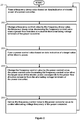
- Figure 2 shows a flowchart of a method according to an exemplifying and non-limiting embodiment for controlling a power converter. The method comprises the following actions:
- a method according to an exemplifying and non-limiting embodiment comprises limiting a rate of change of the power control value to be at most a predetermined upper limit of the rate of change.
- a method comprises computing a time integral of an error value proportional to a difference between the target value of the electric power and the electric power, and correcting the frequency control value with a correction value dependent on the time integral of the error value.
- the error value e.g. p ref - p act
- the correction value is an output value of the proportional and integrative controller
- a method comprises limiting the correction value to be at least a predetermined lower limit of the correction value and at most a predetermined upper limit of the correction value.
- a method comprises preventing an absolute value of the above-mentioned time integral from increasing in response to a situation in which the correction value reaches the predetermined upper limit of the correction value or the predetermined lower limit of the correction value.
- a method comprises forming a voltage droop value based on data indicative of reactive power of the power converter.
- the voltage droop value decreases an amplitude of voltage of the power converter in response to a situation in which the power converter produces inductive reactive power.
- the voltage droop value increases the amplitude of the voltage of the power converter in response to a situation in which the power converter consumes inductive reactive power.
- a computer program according to an exemplifying and non-limiting embodiment comprises computer executable instructions for controlling a programmable processing system to carry out actions related to a method according to any of the above-described exemplifying and non-limiting embodiments.
- a computer program comprises software modules for controlling a power converter.
- the software modules comprise computer executable instructions for controlling a programmable processing system to:
- the software modules can be for example subroutines or functions implemented with programming tools suitable for the programmable processing system.
- a computer readable medium e.g. a compact disc "CD”
- a signal according to an exemplifying and non-limiting embodiment is encoded to carry information defining a computer program according to an exemplifying embodiment of invention.
Landscapes
- Engineering & Computer Science (AREA)
- Power Engineering (AREA)
- Physics & Mathematics (AREA)
- General Physics & Mathematics (AREA)
- Automation & Control Theory (AREA)
- Inverter Devices (AREA)
- Ac-Ac Conversion (AREA)
Priority Applications (6)
| Application Number | Priority Date | Filing Date | Title |
|---|---|---|---|
| FIEP20159044.5T FI3869682T3 (fi) | 2020-02-24 | 2020-02-24 | Menetelmä ja ohjauslaite tehonmuuntimen säätämiseksi |
| EP20159044.5A EP3869682B8 (de) | 2020-02-24 | 2020-02-24 | Verfahren und steuerungsvorrichtung zur steuerung eines stromwandlers |
| JP2021002631A JP7684805B2 (ja) | 2020-02-24 | 2021-01-12 | 電力変換装置を制御するための方法および制御装置 |
| KR1020210004413A KR20210108305A (ko) | 2020-02-24 | 2021-01-13 | 전력 변환기를 제어하기 위한 방법 및 제어 디바이스 |
| CN202110063370.XA CN113381458B (zh) | 2020-02-24 | 2021-01-18 | 用于控制功率变换器的方法和控制装置 |
| US17/182,612 US11831231B2 (en) | 2020-02-24 | 2021-02-23 | Method and a control device for controlling a power converter configured to form a frequency droop value based on electric power supplied to alternating current system |
Applications Claiming Priority (1)
| Application Number | Priority Date | Filing Date | Title |
|---|---|---|---|
| EP20159044.5A EP3869682B8 (de) | 2020-02-24 | 2020-02-24 | Verfahren und steuerungsvorrichtung zur steuerung eines stromwandlers |
Publications (3)
| Publication Number | Publication Date |
|---|---|
| EP3869682A1 true EP3869682A1 (de) | 2021-08-25 |
| EP3869682B1 EP3869682B1 (de) | 2024-04-17 |
| EP3869682B8 EP3869682B8 (de) | 2024-06-12 |
Family
ID=69726493
Family Applications (1)
| Application Number | Title | Priority Date | Filing Date |
|---|---|---|---|
| EP20159044.5A Active EP3869682B8 (de) | 2020-02-24 | 2020-02-24 | Verfahren und steuerungsvorrichtung zur steuerung eines stromwandlers |
Country Status (6)
| Country | Link |
|---|---|
| US (1) | US11831231B2 (de) |
| EP (1) | EP3869682B8 (de) |
| JP (1) | JP7684805B2 (de) |
| KR (1) | KR20210108305A (de) |
| CN (1) | CN113381458B (de) |
| FI (1) | FI3869682T3 (de) |
Families Citing this family (3)
| Publication number | Priority date | Publication date | Assignee | Title |
|---|---|---|---|---|
| WO2022185614A1 (ja) * | 2021-03-03 | 2022-09-09 | 住友電気工業株式会社 | インバータ、並列インバータシステム、及び、インバータの制御方法 |
| EP4254711A1 (de) * | 2022-03-30 | 2023-10-04 | Danfoss Editron Oy | Verfahren und steuersystem zur steuerung von parallel geschalteten leistungswandlern |
| US20250047132A1 (en) * | 2023-08-02 | 2025-02-06 | Caterpillar Inc. | Load sharing techniques for electric power sources |
Citations (2)
| Publication number | Priority date | Publication date | Assignee | Title |
|---|---|---|---|---|
| US20180358907A1 (en) * | 2016-01-20 | 2018-12-13 | Mitsubishi Electric Corporation | Electric power conversion device and electric power conversion system |
| CN109980682A (zh) * | 2019-03-18 | 2019-07-05 | 国网江苏省电力有限公司连云港供电分公司 | 基于功率前馈的vsg储能电站主动频率支撑控制方法 |
Family Cites Families (33)
| Publication number | Priority date | Publication date | Assignee | Title |
|---|---|---|---|---|
| US5798633A (en) * | 1996-07-26 | 1998-08-25 | General Electric Company | Battery energy storage power conditioning system |
| US8760888B2 (en) * | 2006-06-30 | 2014-06-24 | Abb Technology Ag | HVDC system and method to control a voltage source converter in a HVDC system |
| US7920942B2 (en) * | 2007-03-01 | 2011-04-05 | Wisconsin Alumni Research Foundation | Control of combined storage and generation in distributed energy resources |
| FI120808B (fi) * | 2007-11-28 | 2010-03-15 | Abb Oy | Sähköverkon harmonisten kompensoiminen |
| US8693228B2 (en) * | 2009-02-19 | 2014-04-08 | Stefan Matan | Power transfer management for local power sources of a grid-tied load |
| EP2667476B1 (de) * | 2011-01-20 | 2020-07-08 | Kabushiki Kaisha Toshiba | Photovoltaik system und leistungsversorgungsversorgungssystem |
| EP2485378A1 (de) * | 2011-02-08 | 2012-08-08 | Converteam Technology Ltd | Steueranlage und -vorrichtung zur Regulierung der Ausgangsspannung eines Gleichstromrichters, der an ein Mehrquellengleichstromsystem angeschlossen ist |
| ES2402467B1 (es) * | 2011-02-28 | 2014-01-27 | Abengoa Solar New Technologies S.A. | Controlador de potencia síncrona de un sistema de generación basado en convertidores estáticos de potencia. |
| US8606424B2 (en) * | 2011-04-05 | 2013-12-10 | King Fahd University Of Petroleum And Minerals | Particle swarm optimization system and method for microgrids |
| EP2731223B1 (de) | 2011-07-08 | 2016-06-08 | Kawasaki Jukogyo Kabushiki Kaisha | Stromumwandlungsvorrichtung für ein kombinationskraftwerk |
| GB201114868D0 (en) * | 2011-08-30 | 2011-10-12 | Rolls Royce Plc | Method of controlling an inverter and a controller for controlling an inverter |
| TWI415359B (zh) * | 2011-09-16 | 2013-11-11 | Nat Univ Tsing Hua | 用於市電併聯之同步調整的下降控制系統 |
| KR101699410B1 (ko) * | 2012-12-27 | 2017-01-24 | 카와사키 주코교 카부시키 카이샤 | 전력 변환 장치를 구비한 복합 발전 시스템 |
| US10008854B2 (en) * | 2015-02-19 | 2018-06-26 | Enphase Energy, Inc. | Method and apparatus for time-domain droop control with integrated phasor current control |
| CN107431361B (zh) * | 2015-07-02 | 2019-05-07 | 戴纳动力有限责任公司 | 孤岛运行多个并网的功率转换器 |
| JP6684679B2 (ja) * | 2016-08-02 | 2020-04-22 | 三菱重工業株式会社 | 分散電源用電力変換器の制御装置、当該制御装置を有する分散電源システムおよび分散電源用電力変換器の制御方法 |
| GB201613956D0 (en) * | 2016-08-15 | 2016-09-28 | Univ Swansea | Dynamic active and reactive power sharing schemes in islanded microgrids |
| JP6764338B2 (ja) * | 2016-12-27 | 2020-09-30 | 川崎重工業株式会社 | 電源システム |
| US10566797B2 (en) * | 2017-03-13 | 2020-02-18 | Mitsubishi Electric Research Laboratories, Inc. | Power electronic converter based synchronizer for generators |
| EP3872949B1 (de) * | 2017-03-14 | 2025-07-09 | ABB Schweiz AG | Verfahren und steuerungssystem zur steuerung eines stromwandlers |
| GB2563086B (en) * | 2017-06-04 | 2020-09-16 | Zhong Qingchang | Cyber Synchronous Machine (in short, Cybersync Machine) |
| CN107453412B (zh) * | 2017-08-14 | 2019-11-26 | 北方工业大学 | 基于vsg控制装置及方法、多vsg预同步并网方法 |
| CN107482684A (zh) * | 2017-09-19 | 2017-12-15 | 南京南瑞继保电气有限公司 | 一种换流器控制方法 |
| US10566793B2 (en) * | 2017-09-29 | 2020-02-18 | Mitsubishi Electric Research Laboratories, Inc. | Systems and methods for distributed synchronization of micro-grids with multiple points of interconnection |
| US10924035B2 (en) * | 2017-10-16 | 2021-02-16 | Mitsubishi Electric Corporation | Power conversion device |
| FR3076107B1 (fr) * | 2017-12-21 | 2021-02-12 | Socomec Sa | Procede et systeme de regulation d'un convertisseur electrique pour stabilisation autonome de frequence avec des transitoires de charge dans un micro-reseau comprenant un groupe electrogene diesel |
| WO2020084688A1 (ja) * | 2018-10-23 | 2020-04-30 | 三菱電機株式会社 | 系統システム、制御装置及び系統システムの制御方法 |
| US10749446B2 (en) * | 2019-01-02 | 2020-08-18 | General Electric Company | Virtual synchronous generator system and method with virtual inertia control |
| WO2021058079A1 (en) * | 2019-09-23 | 2021-04-01 | Huawei Technologies Co., Ltd. | Control of parallel connected inverters using hopf oscillators |
| US11012016B2 (en) * | 2019-10-14 | 2021-05-18 | Schweitzer Engineering Laboratories, Inc. | Energy packet control of generator prime mover |
| US11146193B2 (en) * | 2019-10-14 | 2021-10-12 | Schweitzer Engineering Laboratories, Inc. | Genset engine paralleling controls, devices, systems, and methods |
| US20220077688A1 (en) * | 2019-12-01 | 2022-03-10 | Juan Felipe Patarroyo | Integrated power sharing control method for three-phase inverter-based generators with applications in microgrids |
| EP3866293A3 (de) * | 2020-01-21 | 2021-12-01 | Vestas Wind Systems A/S | Verfahren zur steuerung einer windturbine |
-
2020
- 2020-02-24 FI FIEP20159044.5T patent/FI3869682T3/fi active
- 2020-02-24 EP EP20159044.5A patent/EP3869682B8/de active Active
-
2021
- 2021-01-12 JP JP2021002631A patent/JP7684805B2/ja active Active
- 2021-01-13 KR KR1020210004413A patent/KR20210108305A/ko active Pending
- 2021-01-18 CN CN202110063370.XA patent/CN113381458B/zh active Active
- 2021-02-23 US US17/182,612 patent/US11831231B2/en active Active
Patent Citations (2)
| Publication number | Priority date | Publication date | Assignee | Title |
|---|---|---|---|---|
| US20180358907A1 (en) * | 2016-01-20 | 2018-12-13 | Mitsubishi Electric Corporation | Electric power conversion device and electric power conversion system |
| CN109980682A (zh) * | 2019-03-18 | 2019-07-05 | 国网江苏省电力有限公司连云港供电分公司 | 基于功率前馈的vsg储能电站主动频率支撑控制方法 |
Non-Patent Citations (2)
| Title |
|---|
| GENG YIWEN ET AL: "A Modified Droop Control for Grid-Connected Inverters With Improved Stability in the Fluctuation of Grid Frequency and Voltage Magnitude", IEEE ACCESS, vol. 7, 31 May 2019 (2019-05-31), pages 75658 - 75669, XP011731136, DOI: 10.1109/ACCESS.2019.2920312 * |
| SHALINI RAOSAHEB BORADE ET AL: "Analysis of Voltage-Frequency (VF) Droop Control Method for AC Microgrid Application", 2 February 2018 (2018-02-02), XP055721735, Retrieved from the Internet <URL:https://www.ijarse.com/images/fullpdf/1518687068_MCCIA3056_IJARSE.pdf> [retrieved on 20200811] * |
Also Published As
| Publication number | Publication date |
|---|---|
| JP7684805B2 (ja) | 2025-05-28 |
| US20210265906A1 (en) | 2021-08-26 |
| CN113381458B (zh) | 2024-11-19 |
| FI3869682T3 (fi) | 2024-07-10 |
| EP3869682B1 (de) | 2024-04-17 |
| KR20210108305A (ko) | 2021-09-02 |
| CN113381458A (zh) | 2021-09-10 |
| EP3869682B8 (de) | 2024-06-12 |
| JP2021136861A (ja) | 2021-09-13 |
| US11831231B2 (en) | 2023-11-28 |
Similar Documents
| Publication | Publication Date | Title |
|---|---|---|
| US10811900B2 (en) | Uninterruptible power supply system and uninterruptible power supply apparatus | |
| EP1364454B1 (de) | Mobiles stromerzeugungssystem | |
| US5798633A (en) | Battery energy storage power conditioning system | |
| US11831231B2 (en) | Method and a control device for controlling a power converter configured to form a frequency droop value based on electric power supplied to alternating current system | |
| US10411478B2 (en) | Grid connection power conversion device and disconnection/welding detection method therefor | |
| EP1338075B1 (de) | Multifunktions-ac/dc-wandler | |
| EP2859644B1 (de) | Verfahren und vorrichtung zur bereitstellung einer unterbrechungsfreien stromversorgung | |
| EP2424102A2 (de) | Gleichstrom/Wechselstrom-Wandler vom Einzelphasenspannungstyp, Gleichstrom/Wechselstrom-Wandler vom Dreiphasenspannungstyp und Stabilisierungssteuerungsverfahren | |
| US12081031B2 (en) | Method for stabilizing the DC voltage in a DC grid, and DC-to-DC converter for connecting a PV generator to a DC grid | |
| EP3905509A1 (de) | Offline-phasentrennvorrichtung und wechselrichtersystem | |
| JP2014099986A (ja) | 複合蓄電システム | |
| EP4262042A1 (de) | Energiespeichersystem | |
| CN115549191A (zh) | 一种储能系统及孤岛检测方法 | |
| CN112997395A (zh) | 电力转换装置 | |
| US12463554B2 (en) | Inverter, parallel inverter system, and method of controlling inverter | |
| US20250226766A1 (en) | A method and a control system for controlling parallel connected power converters | |
| US20250210997A1 (en) | A method and a control system for controlling parallel connected power converters | |
| JP2001136664A (ja) | 分散形発電システム | |
| WO2022264303A1 (ja) | 無停電電源装置 | |
| JP2006136054A (ja) | 無停電電源装置 | |
| RU2743196C1 (ru) | Способ повышения надёжности работы электропривода с многоуровневым инвертором | |
| JP5400955B2 (ja) | 電力変換装置 | |
| CN121688782A (zh) | 供电控制系统及光伏微电网系统 | |
| HK1164559B (en) | Single-phase voltage type ac/dc converter, three-phase voltage type ac/dc converter, and stabilization control method |
Legal Events
| Date | Code | Title | Description |
|---|---|---|---|
| STAA | Information on the status of an ep patent application or granted ep patent |
Free format text: STATUS: EXAMINATION IS IN PROGRESS |
|
| PUAI | Public reference made under article 153(3) epc to a published international application that has entered the european phase |
Free format text: ORIGINAL CODE: 0009012 |
|
| 17P | Request for examination filed |
Effective date: 20201027 |
|
| AK | Designated contracting states |
Kind code of ref document: A1 Designated state(s): AL AT BE BG CH CY CZ DE DK EE ES FI FR GB GR HR HU IE IS IT LI LT LU LV MC MK MT NL NO PL PT RO RS SE SI SK SM TR |
|
| P01 | Opt-out of the competence of the unified patent court (upc) registered |
Effective date: 20230713 |
|
| GRAP | Despatch of communication of intention to grant a patent |
Free format text: ORIGINAL CODE: EPIDOSNIGR1 |
|
| STAA | Information on the status of an ep patent application or granted ep patent |
Free format text: STATUS: GRANT OF PATENT IS INTENDED |
|
| INTG | Intention to grant announced |
Effective date: 20231219 |
|
| GRAS | Grant fee paid |
Free format text: ORIGINAL CODE: EPIDOSNIGR3 |
|
| GRAA | (expected) grant |
Free format text: ORIGINAL CODE: 0009210 |
|
| STAA | Information on the status of an ep patent application or granted ep patent |
Free format text: STATUS: THE PATENT HAS BEEN GRANTED |
|
| AK | Designated contracting states |
Kind code of ref document: B1 Designated state(s): AL AT BE BG CH CY CZ DE DK EE ES FI FR GB GR HR HU IE IS IT LI LT LU LV MC MK MT NL NO PL PT RO RS SE SI SK SM TR |
|
| REG | Reference to a national code |
Ref country code: GB Ref legal event code: FG4D |
|
| REG | Reference to a national code |
Ref country code: CH Ref legal event code: EP |
|
| REG | Reference to a national code |
Ref country code: DE Ref legal event code: R096 Ref document number: 602020029000 Country of ref document: DE |
|
| REG | Reference to a national code |
Ref country code: IE Ref legal event code: FG4D |
|
| REG | Reference to a national code |
Ref country code: DE Ref legal event code: R081 Ref document number: 602020029000 Country of ref document: DE Owner name: DANFOSS A/S, DK Free format text: FORMER OWNER: DANFOSS EDITRON OY, LAPPEENRANTA, FI |
|
| REG | Reference to a national code |
Ref country code: CH Ref legal event code: PK Free format text: BERICHTIGUNG B8 |
|
| RAP2 | Party data changed (patent owner data changed or rights of a patent transferred) |
Owner name: DANFOSS A/S |
|
| REG | Reference to a national code |
Ref country code: SE Ref legal event code: TRGR |
|
| REG | Reference to a national code |
Ref country code: FI Ref legal event code: FGE |
|
| REG | Reference to a national code |
Ref country code: LT Ref legal event code: MG9D |
|
| REG | Reference to a national code |
Ref country code: NL Ref legal event code: MP Effective date: 20240417 |
|
| REG | Reference to a national code |
Ref country code: AT Ref legal event code: MK05 Ref document number: 1678224 Country of ref document: AT Kind code of ref document: T Effective date: 20240417 |
|
| PG25 | Lapsed in a contracting state [announced via postgrant information from national office to epo] |
Ref country code: NL Free format text: LAPSE BECAUSE OF FAILURE TO SUBMIT A TRANSLATION OF THE DESCRIPTION OR TO PAY THE FEE WITHIN THE PRESCRIBED TIME-LIMIT Effective date: 20240417 |
|
| PG25 | Lapsed in a contracting state [announced via postgrant information from national office to epo] |
Ref country code: NL Free format text: LAPSE BECAUSE OF FAILURE TO SUBMIT A TRANSLATION OF THE DESCRIPTION OR TO PAY THE FEE WITHIN THE PRESCRIBED TIME-LIMIT Effective date: 20240417 |
|
| PG25 | Lapsed in a contracting state [announced via postgrant information from national office to epo] |
Ref country code: IS Free format text: LAPSE BECAUSE OF FAILURE TO SUBMIT A TRANSLATION OF THE DESCRIPTION OR TO PAY THE FEE WITHIN THE PRESCRIBED TIME-LIMIT Effective date: 20240817 |
|
| PG25 | Lapsed in a contracting state [announced via postgrant information from national office to epo] |
Ref country code: BG Free format text: LAPSE BECAUSE OF FAILURE TO SUBMIT A TRANSLATION OF THE DESCRIPTION OR TO PAY THE FEE WITHIN THE PRESCRIBED TIME-LIMIT Effective date: 20240417 |
|
| PG25 | Lapsed in a contracting state [announced via postgrant information from national office to epo] |
Ref country code: HR Free format text: LAPSE BECAUSE OF FAILURE TO SUBMIT A TRANSLATION OF THE DESCRIPTION OR TO PAY THE FEE WITHIN THE PRESCRIBED TIME-LIMIT Effective date: 20240417 |
|
| PG25 | Lapsed in a contracting state [announced via postgrant information from national office to epo] |
Ref country code: GR Free format text: LAPSE BECAUSE OF FAILURE TO SUBMIT A TRANSLATION OF THE DESCRIPTION OR TO PAY THE FEE WITHIN THE PRESCRIBED TIME-LIMIT Effective date: 20240718 |
|
| PG25 | Lapsed in a contracting state [announced via postgrant information from national office to epo] |
Ref country code: PT Free format text: LAPSE BECAUSE OF FAILURE TO SUBMIT A TRANSLATION OF THE DESCRIPTION OR TO PAY THE FEE WITHIN THE PRESCRIBED TIME-LIMIT Effective date: 20240819 |
|
| PG25 | Lapsed in a contracting state [announced via postgrant information from national office to epo] |
Ref country code: ES Free format text: LAPSE BECAUSE OF FAILURE TO SUBMIT A TRANSLATION OF THE DESCRIPTION OR TO PAY THE FEE WITHIN THE PRESCRIBED TIME-LIMIT Effective date: 20240417 |
|
| PG25 | Lapsed in a contracting state [announced via postgrant information from national office to epo] |
Ref country code: AT Free format text: LAPSE BECAUSE OF FAILURE TO SUBMIT A TRANSLATION OF THE DESCRIPTION OR TO PAY THE FEE WITHIN THE PRESCRIBED TIME-LIMIT Effective date: 20240417 |
|
| PG25 | Lapsed in a contracting state [announced via postgrant information from national office to epo] |
Ref country code: PL Free format text: LAPSE BECAUSE OF FAILURE TO SUBMIT A TRANSLATION OF THE DESCRIPTION OR TO PAY THE FEE WITHIN THE PRESCRIBED TIME-LIMIT Effective date: 20240417 |
|
| PG25 | Lapsed in a contracting state [announced via postgrant information from national office to epo] |
Ref country code: LV Free format text: LAPSE BECAUSE OF FAILURE TO SUBMIT A TRANSLATION OF THE DESCRIPTION OR TO PAY THE FEE WITHIN THE PRESCRIBED TIME-LIMIT Effective date: 20240417 |
|
| PG25 | Lapsed in a contracting state [announced via postgrant information from national office to epo] |
Ref country code: PT Free format text: LAPSE BECAUSE OF FAILURE TO SUBMIT A TRANSLATION OF THE DESCRIPTION OR TO PAY THE FEE WITHIN THE PRESCRIBED TIME-LIMIT Effective date: 20240819 Ref country code: PL Free format text: LAPSE BECAUSE OF FAILURE TO SUBMIT A TRANSLATION OF THE DESCRIPTION OR TO PAY THE FEE WITHIN THE PRESCRIBED TIME-LIMIT Effective date: 20240417 Ref country code: LV Free format text: LAPSE BECAUSE OF FAILURE TO SUBMIT A TRANSLATION OF THE DESCRIPTION OR TO PAY THE FEE WITHIN THE PRESCRIBED TIME-LIMIT Effective date: 20240417 Ref country code: IS Free format text: LAPSE BECAUSE OF FAILURE TO SUBMIT A TRANSLATION OF THE DESCRIPTION OR TO PAY THE FEE WITHIN THE PRESCRIBED TIME-LIMIT Effective date: 20240817 Ref country code: HR Free format text: LAPSE BECAUSE OF FAILURE TO SUBMIT A TRANSLATION OF THE DESCRIPTION OR TO PAY THE FEE WITHIN THE PRESCRIBED TIME-LIMIT Effective date: 20240417 Ref country code: GR Free format text: LAPSE BECAUSE OF FAILURE TO SUBMIT A TRANSLATION OF THE DESCRIPTION OR TO PAY THE FEE WITHIN THE PRESCRIBED TIME-LIMIT Effective date: 20240718 Ref country code: ES Free format text: LAPSE BECAUSE OF FAILURE TO SUBMIT A TRANSLATION OF THE DESCRIPTION OR TO PAY THE FEE WITHIN THE PRESCRIBED TIME-LIMIT Effective date: 20240417 Ref country code: BG Free format text: LAPSE BECAUSE OF FAILURE TO SUBMIT A TRANSLATION OF THE DESCRIPTION OR TO PAY THE FEE WITHIN THE PRESCRIBED TIME-LIMIT Effective date: 20240417 Ref country code: AT Free format text: LAPSE BECAUSE OF FAILURE TO SUBMIT A TRANSLATION OF THE DESCRIPTION OR TO PAY THE FEE WITHIN THE PRESCRIBED TIME-LIMIT Effective date: 20240417 Ref country code: RS Free format text: LAPSE BECAUSE OF FAILURE TO SUBMIT A TRANSLATION OF THE DESCRIPTION OR TO PAY THE FEE WITHIN THE PRESCRIBED TIME-LIMIT Effective date: 20240717 |
|
| PG25 | Lapsed in a contracting state [announced via postgrant information from national office to epo] |
Ref country code: DK Free format text: LAPSE BECAUSE OF FAILURE TO SUBMIT A TRANSLATION OF THE DESCRIPTION OR TO PAY THE FEE WITHIN THE PRESCRIBED TIME-LIMIT Effective date: 20240417 |
|
| REG | Reference to a national code |
Ref country code: DE Ref legal event code: R097 Ref document number: 602020029000 Country of ref document: DE |
|
| PG25 | Lapsed in a contracting state [announced via postgrant information from national office to epo] |
Ref country code: EE Free format text: LAPSE BECAUSE OF FAILURE TO SUBMIT A TRANSLATION OF THE DESCRIPTION OR TO PAY THE FEE WITHIN THE PRESCRIBED TIME-LIMIT Effective date: 20240417 |
|
| PG25 | Lapsed in a contracting state [announced via postgrant information from national office to epo] |
Ref country code: CZ Free format text: LAPSE BECAUSE OF FAILURE TO SUBMIT A TRANSLATION OF THE DESCRIPTION OR TO PAY THE FEE WITHIN THE PRESCRIBED TIME-LIMIT Effective date: 20240417 |
|
| PG25 | Lapsed in a contracting state [announced via postgrant information from national office to epo] |
Ref country code: SK Free format text: LAPSE BECAUSE OF FAILURE TO SUBMIT A TRANSLATION OF THE DESCRIPTION OR TO PAY THE FEE WITHIN THE PRESCRIBED TIME-LIMIT Effective date: 20240417 Ref country code: RO Free format text: LAPSE BECAUSE OF FAILURE TO SUBMIT A TRANSLATION OF THE DESCRIPTION OR TO PAY THE FEE WITHIN THE PRESCRIBED TIME-LIMIT Effective date: 20240417 |
|
| PG25 | Lapsed in a contracting state [announced via postgrant information from national office to epo] |
Ref country code: SM Free format text: LAPSE BECAUSE OF FAILURE TO SUBMIT A TRANSLATION OF THE DESCRIPTION OR TO PAY THE FEE WITHIN THE PRESCRIBED TIME-LIMIT Effective date: 20240417 |
|
| PG25 | Lapsed in a contracting state [announced via postgrant information from national office to epo] |
Ref country code: SM Free format text: LAPSE BECAUSE OF FAILURE TO SUBMIT A TRANSLATION OF THE DESCRIPTION OR TO PAY THE FEE WITHIN THE PRESCRIBED TIME-LIMIT Effective date: 20240417 Ref country code: SK Free format text: LAPSE BECAUSE OF FAILURE TO SUBMIT A TRANSLATION OF THE DESCRIPTION OR TO PAY THE FEE WITHIN THE PRESCRIBED TIME-LIMIT Effective date: 20240417 Ref country code: RO Free format text: LAPSE BECAUSE OF FAILURE TO SUBMIT A TRANSLATION OF THE DESCRIPTION OR TO PAY THE FEE WITHIN THE PRESCRIBED TIME-LIMIT Effective date: 20240417 Ref country code: EE Free format text: LAPSE BECAUSE OF FAILURE TO SUBMIT A TRANSLATION OF THE DESCRIPTION OR TO PAY THE FEE WITHIN THE PRESCRIBED TIME-LIMIT Effective date: 20240417 Ref country code: DK Free format text: LAPSE BECAUSE OF FAILURE TO SUBMIT A TRANSLATION OF THE DESCRIPTION OR TO PAY THE FEE WITHIN THE PRESCRIBED TIME-LIMIT Effective date: 20240417 Ref country code: CZ Free format text: LAPSE BECAUSE OF FAILURE TO SUBMIT A TRANSLATION OF THE DESCRIPTION OR TO PAY THE FEE WITHIN THE PRESCRIBED TIME-LIMIT Effective date: 20240417 |
|
| PLBE | No opposition filed within time limit |
Free format text: ORIGINAL CODE: 0009261 |
|
| STAA | Information on the status of an ep patent application or granted ep patent |
Free format text: STATUS: NO OPPOSITION FILED WITHIN TIME LIMIT |
|
| 26N | No opposition filed |
Effective date: 20250120 |
|
| PG25 | Lapsed in a contracting state [announced via postgrant information from national office to epo] |
Ref country code: SI Free format text: LAPSE BECAUSE OF FAILURE TO SUBMIT A TRANSLATION OF THE DESCRIPTION OR TO PAY THE FEE WITHIN THE PRESCRIBED TIME-LIMIT Effective date: 20240417 |
|
| PG25 | Lapsed in a contracting state [announced via postgrant information from national office to epo] |
Ref country code: MC Free format text: LAPSE BECAUSE OF FAILURE TO SUBMIT A TRANSLATION OF THE DESCRIPTION OR TO PAY THE FEE WITHIN THE PRESCRIBED TIME-LIMIT Effective date: 20240417 |
|
| REG | Reference to a national code |
Ref country code: CH Ref legal event code: PL |
|
| PG25 | Lapsed in a contracting state [announced via postgrant information from national office to epo] |
Ref country code: LU Free format text: LAPSE BECAUSE OF NON-PAYMENT OF DUE FEES Effective date: 20250224 |
|
| PG25 | Lapsed in a contracting state [announced via postgrant information from national office to epo] |
Ref country code: CH Free format text: LAPSE BECAUSE OF NON-PAYMENT OF DUE FEES Effective date: 20250228 |
|
| REG | Reference to a national code |
Ref country code: BE Ref legal event code: MM Effective date: 20250228 |
|
| PGFP | Annual fee paid to national office [announced via postgrant information from national office to epo] |
Ref country code: FR Payment date: 20251231 Year of fee payment: 7 |
|
| PG25 | Lapsed in a contracting state [announced via postgrant information from national office to epo] |
Ref country code: BE Free format text: LAPSE BECAUSE OF NON-PAYMENT OF DUE FEES Effective date: 20250228 |
|
| PG25 | Lapsed in a contracting state [announced via postgrant information from national office to epo] |
Ref country code: IE Free format text: LAPSE BECAUSE OF NON-PAYMENT OF DUE FEES Effective date: 20250224 |
|
| PGFP | Annual fee paid to national office [announced via postgrant information from national office to epo] |
Ref country code: SE Payment date: 20260105 Year of fee payment: 7 |
|
| PGFP | Annual fee paid to national office [announced via postgrant information from national office to epo] |
Ref country code: GB Payment date: 20260106 Year of fee payment: 7 |
|
| PGFP | Annual fee paid to national office [announced via postgrant information from national office to epo] |
Ref country code: DE Payment date: 20260102 Year of fee payment: 7 Ref country code: NO Payment date: 20260211 Year of fee payment: 7 |
|
| PGFP | Annual fee paid to national office [announced via postgrant information from national office to epo] |
Ref country code: FI Payment date: 20260213 Year of fee payment: 7 Ref country code: IT Payment date: 20260122 Year of fee payment: 7 |