EP3868613A1 - Vehicle occupant rerstraining device - Google Patents
Vehicle occupant rerstraining device Download PDFInfo
- Publication number
- EP3868613A1 EP3868613A1 EP19873381.8A EP19873381A EP3868613A1 EP 3868613 A1 EP3868613 A1 EP 3868613A1 EP 19873381 A EP19873381 A EP 19873381A EP 3868613 A1 EP3868613 A1 EP 3868613A1
- Authority
- EP
- European Patent Office
- Prior art keywords
- seat
- occupant
- pair
- airbag
- airbags
- Prior art date
- Legal status (The legal status is an assumption and is not a legal conclusion. Google has not performed a legal analysis and makes no representation as to the accuracy of the status listed.)
- Pending
Links
Images


Classifications
-
- B—PERFORMING OPERATIONS; TRANSPORTING
- B60—VEHICLES IN GENERAL
- B60R—VEHICLES, VEHICLE FITTINGS, OR VEHICLE PARTS, NOT OTHERWISE PROVIDED FOR
- B60R21/00—Arrangements or fittings on vehicles for protecting or preventing injuries to occupants or pedestrians in case of accidents or other traffic risks
- B60R21/02—Occupant safety arrangements or fittings, e.g. crash pads
- B60R21/16—Inflatable occupant restraints or confinements designed to inflate upon impact or impending impact, e.g. air bags
- B60R21/20—Arrangements for storing inflatable members in their non-use or deflated condition; Arrangement or mounting of air bag modules or components
- B60R21/207—Arrangements for storing inflatable members in their non-use or deflated condition; Arrangement or mounting of air bag modules or components in vehicle seats
-
- B—PERFORMING OPERATIONS; TRANSPORTING
- B60—VEHICLES IN GENERAL
- B60R—VEHICLES, VEHICLE FITTINGS, OR VEHICLE PARTS, NOT OTHERWISE PROVIDED FOR
- B60R21/00—Arrangements or fittings on vehicles for protecting or preventing injuries to occupants or pedestrians in case of accidents or other traffic risks
- B60R21/02—Occupant safety arrangements or fittings, e.g. crash pads
- B60R21/16—Inflatable occupant restraints or confinements designed to inflate upon impact or impending impact, e.g. air bags
- B60R21/20—Arrangements for storing inflatable members in their non-use or deflated condition; Arrangement or mounting of air bag modules or components
- B60R21/215—Arrangements for storing inflatable members in their non-use or deflated condition; Arrangement or mounting of air bag modules or components characterised by the covers for the inflatable member
-
- B—PERFORMING OPERATIONS; TRANSPORTING
- B60—VEHICLES IN GENERAL
- B60R—VEHICLES, VEHICLE FITTINGS, OR VEHICLE PARTS, NOT OTHERWISE PROVIDED FOR
- B60R21/00—Arrangements or fittings on vehicles for protecting or preventing injuries to occupants or pedestrians in case of accidents or other traffic risks
- B60R21/02—Occupant safety arrangements or fittings, e.g. crash pads
- B60R21/16—Inflatable occupant restraints or confinements designed to inflate upon impact or impending impact, e.g. air bags
- B60R21/23—Inflatable members
- B60R21/231—Inflatable members characterised by their shape, construction or spatial configuration
- B60R21/23138—Inflatable members characterised by their shape, construction or spatial configuration specially adapted for side protection
-
- B—PERFORMING OPERATIONS; TRANSPORTING
- B60—VEHICLES IN GENERAL
- B60R—VEHICLES, VEHICLE FITTINGS, OR VEHICLE PARTS, NOT OTHERWISE PROVIDED FOR
- B60R21/00—Arrangements or fittings on vehicles for protecting or preventing injuries to occupants or pedestrians in case of accidents or other traffic risks
- B60R21/02—Occupant safety arrangements or fittings, e.g. crash pads
- B60R21/16—Inflatable occupant restraints or confinements designed to inflate upon impact or impending impact, e.g. air bags
- B60R21/23—Inflatable members
- B60R21/231—Inflatable members characterised by their shape, construction or spatial configuration
- B60R21/233—Inflatable members characterised by their shape, construction or spatial configuration comprising a plurality of individual compartments; comprising two or more bag-like members, one within the other
-
- B—PERFORMING OPERATIONS; TRANSPORTING
- B60—VEHICLES IN GENERAL
- B60R—VEHICLES, VEHICLE FITTINGS, OR VEHICLE PARTS, NOT OTHERWISE PROVIDED FOR
- B60R21/00—Arrangements or fittings on vehicles for protecting or preventing injuries to occupants or pedestrians in case of accidents or other traffic risks
- B60R21/02—Occupant safety arrangements or fittings, e.g. crash pads
- B60R21/16—Inflatable occupant restraints or confinements designed to inflate upon impact or impending impact, e.g. air bags
- B60R21/23—Inflatable members
- B60R21/231—Inflatable members characterised by their shape, construction or spatial configuration
- B60R21/2334—Expansion control features
- B60R21/2338—Tethers
-
- B—PERFORMING OPERATIONS; TRANSPORTING
- B60—VEHICLES IN GENERAL
- B60R—VEHICLES, VEHICLE FITTINGS, OR VEHICLE PARTS, NOT OTHERWISE PROVIDED FOR
- B60R21/00—Arrangements or fittings on vehicles for protecting or preventing injuries to occupants or pedestrians in case of accidents or other traffic risks
- B60R21/02—Occupant safety arrangements or fittings, e.g. crash pads
- B60R21/16—Inflatable occupant restraints or confinements designed to inflate upon impact or impending impact, e.g. air bags
- B60R2021/161—Inflatable occupant restraints or confinements designed to inflate upon impact or impending impact, e.g. air bags characterised by additional means for controlling deployment trajectory
-
- B—PERFORMING OPERATIONS; TRANSPORTING
- B60—VEHICLES IN GENERAL
- B60R—VEHICLES, VEHICLE FITTINGS, OR VEHICLE PARTS, NOT OTHERWISE PROVIDED FOR
- B60R21/00—Arrangements or fittings on vehicles for protecting or preventing injuries to occupants or pedestrians in case of accidents or other traffic risks
- B60R21/02—Occupant safety arrangements or fittings, e.g. crash pads
- B60R21/16—Inflatable occupant restraints or confinements designed to inflate upon impact or impending impact, e.g. air bags
- B60R21/23—Inflatable members
- B60R21/231—Inflatable members characterised by their shape, construction or spatial configuration
- B60R21/233—Inflatable members characterised by their shape, construction or spatial configuration comprising a plurality of individual compartments; comprising two or more bag-like members, one within the other
- B60R2021/23324—Inner walls crating separate compartments, e.g. communicating with vents
- B60R2021/23332—Inner walls crating separate compartments, e.g. communicating with vents using independent bags, one within the other
-
- B—PERFORMING OPERATIONS; TRANSPORTING
- B60—VEHICLES IN GENERAL
- B60R—VEHICLES, VEHICLE FITTINGS, OR VEHICLE PARTS, NOT OTHERWISE PROVIDED FOR
- B60R21/00—Arrangements or fittings on vehicles for protecting or preventing injuries to occupants or pedestrians in case of accidents or other traffic risks
- B60R21/02—Occupant safety arrangements or fittings, e.g. crash pads
- B60R21/16—Inflatable occupant restraints or confinements designed to inflate upon impact or impending impact, e.g. air bags
- B60R21/23—Inflatable members
- B60R21/231—Inflatable members characterised by their shape, construction or spatial configuration
- B60R21/2334—Expansion control features
- B60R21/2338—Tethers
- B60R2021/23386—External tether means
- B60R2021/23388—External tether means having ends which are movable or detachable during deployment
Definitions
- the present invention relates to an occupant restraining device that restrains an occupant sitting on a seat of a vehicle.
- Airbag devices have generally become standard equipment in vehicles in recent years.
- An airbag device is a safety device which is operated in case of an emergency such as a vehicle collision and, for example, expands and deploys to protect the occupant.
- a tensile cloth is provided that is tensioned during expansion and deployment of the airbag and extends between both sides of the airbag and the seat cushion.
- Patent Document 1 WO 2016-039160
- an object of the present invention is to provide an occupant restraining device capable of further improving occupant restraining performance with a structure having tensile cloth that deploys on the side part of a seat during expansion and deployment of an airbag.
- a typical configuration of the occupant restraining device of the present invention includes a pair of airbags stowed inside the seatback of a seat that expand and deploy respectively to both sides of an occupant seated in a seat, an inner bag that is stowed inside at least a first of the pair of airbags and is connected to the at least the first airbag and expands and deploys inside the at least first airbag to the side of the torso of the occupant, and a pair of tensile cloths stowed from within the seatback of the seat to within the seat cushion along a side of the stowed pair of airbags opposite the occupant respectively, wherein the inner bag completes expansion and deployment prior to at least a first of the airbags, and the pair of tensile cloths deploy to the side of the seat by expansion and deployment of the pair of airbags and are stretched from the seatback to the seat cushion to retain the pair of airbags on the side opposite the occupant.
- the expanded and deployed airbag is biased towards the occupant by the tensile cloth. This enables suppressing movement of the airbag in a direction away from the occupant and restraining of the occupant more securely.
- an inner bag is stowed inside the airbag.
- the inner bag has a smaller volume than the airbag being contained within the airbag, and therefore requires less gas to expand and deploy. Therefore, the inner bag completes expansion earlier than the airbag.
- the torso of the occupant can be restrained quickly in the event of a collision, especially a side impact, and the occupant restraining performance can be further improved.
- the front end of the inner bag is arranged at or behind a position overlapping at least a first of the pair of tensile cloths in a side view when at least a first airbag expands and deploys.
- another configuration of the occupant restraining device is an occupant restraining device for restraining an occupant seated in a seat of a vehicle, including a pair of airbags stowed in a seatback of a seat that expand and deploy respectively on both sides of an occupant seated in the seat; a partition wall arranged inside at least a first of the pair of airbags that divide at least a first of the airbags into front and rear portions; a connecting hole formed in the partition wall; and a pair of tensile cloths stowed from within the seatback of the seat to within the seat cushion along the stowed pair of airbags respectively on the side opposite the occupant, wherein at least the first of the airbags completes expansion and deployment of the space behind the partition wall before the space in front of the partition wall, and the pair of tensile cloths are deployed to the side of the seat by the expansion and deployment of the pair of airbags and are stretched from the
- the expanded and deployed airbag is again biased towards the occupant by the tensile cloth. This enables suppressing movement of the airbag in a direction away from the occupant and restraining of the occupant more securely.
- the interior of the airbag is partitioned into two spaces in the front-rear direction by a partition wall.
- the space in front of the partition wall is hereinafter referred to as the front chamber
- the space behind the partition wall is referred to as the rear chamber.
- the rear chamber is positioned to the side of the torso of the occupant and expands and deploys before the front chamber.
- the partition wall is arranged at or behind a position overlapping at least a first of the pair of tensile cloths in a side view when at least a first airbag expands and deploys.
- At least a first airbag described above may include an airbag positioned on the near side of the occupant. This enables suitable prevention of contact between the occupant and the vehicle body in the event of a side collision. Note, of the left and right sides of the occupant seated in a seat, the near side is the side on the vehicle body side, and of the left and right sides of the occupant seated in a seat, the far side is the side that is not on the vehicle body side.
- the pair of tensile cloths described above may be deployed along the side of the seat by breaking the seat surface skin.
- the occupant restraining device may have a pair of cases arranged along the side of the seat for stowing the pair of airbags and the pair of tensile cloths, and the pair of tensile cloths may be deployed from the pair of cases to the side of the seat.
- an occupant restraining device capable of further improving occupant restraining performance in a configuration provided with a tensile cloth that is deployed along the side of a seat during expansion and deployment of an airbag can be provided.
- any diagrams used in descriptions below will indicate the front, rear, left, right, up, and down directions based on the occupant as described above as Fr, Rr, L, R, Up, and Down.
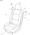
- FIG. 1 is a diagram illustrating an occupant restraining device 100 according to embodiment 1.
- FIG. 1 illustrates the members stowed inside a seat 110 using hidden lines.
- the seat is illustrated with the airbag not expanded and deployed.
- the occupant restraining device 100 of the present embodiment is a device for restraining an occupant that is seated in the seat 110.
- the occupant restraining device 100 of embodiment 1 includes the seat 110, airbags 120a and 120b, left side tensile cloth 130a, and right side tensile cloth 130b of the vehicle (full vehicle not shown).
- the seat 110 includes a seatback 112 that supports the upper body of the occupant.
- a seat cushion 114 is provided below the seatback 112 on which the occupant sits.
- a headrest 116 is provided above the seatback that supports the head of the occupant.
- the pair of airbags 120a and 120b are stowed in both the left and right sides of the seatback 112 of the seat 110, which are covered by covers 118.
- the cover 118 includes a part of the outer skin of the seat 110.
- the pair of airbags 120a and 120b expand and deploy on both sides of the occupant seated in the seat 110 during a collision or the like of the vehicle.
- a structure where a cover 118 is integrated with the surface skin of the seat is illustrated but is not limited thereto, and the seat surface skin and cover can be separate.
- a pair of tensile cloths 130a and 130b are provided for each of the airbags 120a and 120b in this embodiment.
- the pair of tensile cloths 130a and 130b are respectively stored from inside the seatback 112 of the seat 110 to in the seat cushion 114 through the side of the stored pair of airbags 120a and 120b opposite the occupant.
- FIG. 2 , FIG. 3 and FIG. 4 are diagrams that illustrate the state of the airbags 120a and 120b of FIG. 1 during expansion and deployment.
- FIGS. 2(a) and 2(b) illustrate a state in which an occupant P is seated in the seat 110 illustrated in FIG. 1 , and a state where the airbags 120a and 120b are expanded and deployed is observed from above.
- FIG. 3 and FIG. 4 illustrate a state where an occupant P is seated in the seat 110 illustrated in FIG. 1 , and a state where the airbag 120a having been expanded and deployed is observed from the side.
- a vehicle body 102 is positioned on the left side. Accordingly, with regards to the left/right pair of airbags 120a and 120b, the airbag 120a on the left side is an airbag positioned on the near side and the airbag 120b on the right side is an airbag positioned on the far side.
- the inner bag 140 is housed in a rearward area inside the left airbag 120a (nearside airbag) facing the vehicle body side 102 of the left and right pairs of airbags 120a and 120b.
- the inner bag 140 has a smaller volume than the airbag 120a because it is stowed inside the airbag 120a. Therefore, expansion and deployment of the inner bag 140 is completed with a smaller amount of gas than that for the airbag 120a.
- An inner vent 142 is formed in the inner bag 140.
- the airbag 120a and the inner bag 140 are connected at the inner vent 142.
- gas is supplied to the inner bag 140 by an inflator (not illustrated). Therefore, the inner bag 140 completes expansion and deployment before the airbag 120a, as illustrated in FIG. 2(a) .
- the inner bag 140 expands and deploys to the side of the torso P1 (see FIG. 3 ) of the occupant P inside the airbag 120a because the inner bag 140 is arranged in the rearward area of the airbag 120a.
- gas then flows out of the inner vent 142 of the inner bag 140, supplying gas to the airbag 120a. This completes expansion and deployment of the airbag 120a, as illustrated in FIG. 2(b) .
- the inner bag 140 which has a smaller capacity than the airbag 120a, expands and deploys to the side of the torso P1 of the occupant P before the airbag 120a. This allows the torso P1 of the occupant P to be restrained quickly during a collision. Therefore, high occupant restraining performance can be obtained by the occupant restraining device 100.
- the front end 140a of the inner bag 140 is arranged at a position overlapping with the tensile cloth 130a in a side view when the airbag 120a is expanded and deployed.
- the tensile cloth 130a does not stretch across the inner bag 140, and the tensile cloth 130a does not inhibit the expansion and deployment of the inner bag 140. Therefore, the effects described above can reliably be obtained.
- a configuration in which the front end 140a of the inner bag 140 is arranged at a position overlapping with the tensile cloth 130a is illustrated, but is not limited thereto.
- the same effect can be obtained in a configuration in which the front end 140a of the inner bag 140 is arranged behind the position where the inner bag 140 overlaps with the tensile cloth 130a, that is, in a configuration in which the inner bag 140 and the tensile cloth 130a do not overlap in a side view.
- the tensile cloths 130a and 130b deploy to the side of the seat 110 by breaking open the surface skin of the seat 110. Therefore, the tensile cloths 130a and 130b are stretched from the seatback 112 to the seat cushion 114, and the surfaces opposite the occupant P of the airbags 120a and 120b, respectively, are retained by the tensile cloths 130a and 130b. Furthermore, the airbags 120a and 120b are then biased against the occupant P by the tensile cloths 130a and 130b, thereby enhancing the occupant restraining performance of the airbags 120a and 120b.
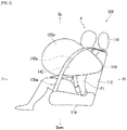
- FIG. 5 , FIG. 6 , and FIG. 7 are diagrams illustrating an occupant restraining device 200 in embodiment 2.
- FIGS. 5(a) and (b) illustrate a state in which an occupant P is seated in the seat 110 illustrated in FIG. 1 , and a state where the airbags 120a and 120b having been expanded and deployed is observed from above.
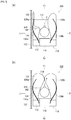
- FIG. 6 and FIG. 7 illustrate a state where an occupant P is seated in the seat 110 illustrated in FIG. 1 , and the state where the airbag 120a having been expanded and deployed is observed from the side. Note that all components in embodiment 2 that are common with those of embodiment 1 are given the same sign and their explanations are omitted.
- a partition wall 240 is provided inside the airbag 120a instead of the inner bag 140 in embodiment 1.
- the partition wall 240 demarcates the interior of the airbag 120a into front and rear sections.
- the space in front of the partition wall 240 is hereinafter referred to as the front chamber 122
- the space behind the partition wall 240 is referred to as the rear chamber 124.
- a connecting hole 242 is formed in the partition wall 240. This connects the front chamber 122 to the rear chamber 124.
- the rear chamber 124 is arranged to the side of the torso P1 of the occupant P.
- gas is supplied to the rear chamber 124 by an inflator (not illustrated). Therefore, with the airbag 120a, the rear chamber 124 completes expansion and deployment before the front chamber 122, as illustrated in FIG. 5 (a) .
- the rear chamber 124 expands and deploys to the side of the torso P1 of the occupant P (see FIG. 3 ), thereby quickly restraining the torso P1 of the occupant P in the event of a collision. Accordingly, high occupant restraining performance can be achieved by the occupant restraining device 200 during a collision, especially during a side impact.
- the partition wall 240 is arranged at a position overlapping with the tensile cloth 130a in a side view when the airbag 120a is expanded and deployed.
- the tensile cloth 130a does not stretch across the rear chamber 124, and the tensile cloth 130a does not inhibit expansion and deployment of the rear chamber 124. Therefore, the effects described above can reliably be obtained.
- a configuration in which the partition wall 240 is arranged at a position overlapping with the tensile cloth 130a is illustrated, but is not limited thereto.
- the same effect can be obtained in a configuration in which the partition wall 240 is arranged rearward of the position where it overlaps with the tensile cloth 130a, in other words, in a configuration in which the rear chamber 124 and the tensile cloth 130a do not overlap in a side view.
- both the occupant restraining device 100 of embodiment 1 and the occupant restraining device 200 of embodiment 2 illustrate configurations in which the left side airbag 120a located on the near side has an inner bag 140 or a partition wall 240.
- FIG. 8 is a diagram illustrating another example of an occupant restraining device.
- the occupant restraining device 300 illustrated in FIG. 8 includes cases 118a and 118b arranged along the side of the seat 110.
- Case 118a is the case where airbags 120a and 120b are stowed and case 118b is the case where tensile cloths 130a and 130b are stowed.
- the tensile cloths 130a and 130b are deployed from the case 118b to the side of the seat 110 during expansion and deployment of the airbags 120a and 120b.
- This configuration will also provide the same effects as the occupant restraining device 100 described above.
- the present invention can be used in an occupant restraining device that restrains an occupant sitting on a seat of a vehicle.
- P1...torso 100...occupant restraining device, 102...vehicle body, 110...seat, 112...seatback, 114...seat cushion, 116...head rest, 118...cover, 118a and 118b...cases, 120a...airbag, 120b...airbag, 122...front chamber, 124...rear chamber, 130a...tensile cloth, 130b...tensile cloth, 140...inner bag, 140a...front end, 142... Inner vent, 200...occupant restraining device, 240...partition wall, 242...connecting hole, 300...occupant restraining device, P...occupant
Abstract
Description
- The present invention relates to an occupant restraining device that restrains an occupant sitting on a seat of a vehicle.
- Airbag devices have generally become standard equipment in vehicles in recent years. An airbag device is a safety device which is operated in case of an emergency such as a vehicle collision and, for example, expands and deploys to protect the occupant. There are various types of airbag devices depending on the installation site and application. For example, a side airbag that expands and deploys to the immediate sides of an occupant on both sides of a seat is provided in an occupant restraining device in Patent Document 1.
- In particular, in the occupant restraining device of Patent Document 1, a tensile cloth is provided that is tensioned during expansion and deployment of the airbag and extends between both sides of the airbag and the seat cushion. Thereby, an effect of suppressing movement of the airbag in the left-right direction by the tensile cloth can be increased. Therefore, occupant restraining performance by the airbag can be further increased.
- [Patent Document 1]
WO 2016-039160 - According to the occupant restraining device of Patent Document 1, movement of the airbag in a direction away from the occupant can be suitably controlled by the tensile cloth, particularly in the left-right direction, and occupant restraining performance by the airbag has increased dramatically. However, there is always a need to improve occupant restraining performance for occupant restraining devices. For this reason, the inventors investigated further improvement of the technology of Patent Document 1.
- In light of this type of problem, an object of the present invention is to provide an occupant restraining device capable of further improving occupant restraining performance with a structure having tensile cloth that deploys on the side part of a seat during expansion and deployment of an airbag.
- In order to resolve the problems described above, a typical configuration of the occupant restraining device of the present invention includes a pair of airbags stowed inside the seatback of a seat that expand and deploy respectively to both sides of an occupant seated in a seat, an inner bag that is stowed inside at least a first of the pair of airbags and is connected to the at least the first airbag and expands and deploys inside the at least first airbag to the side of the torso of the occupant, and a pair of tensile cloths stowed from within the seatback of the seat to within the seat cushion along a side of the stowed pair of airbags opposite the occupant respectively, wherein the inner bag completes expansion and deployment prior to at least a first of the airbags, and the pair of tensile cloths deploy to the side of the seat by expansion and deployment of the pair of airbags and are stretched from the seatback to the seat cushion to retain the pair of airbags on the side opposite the occupant.
- According to the above configuration, the expanded and deployed airbag is biased towards the occupant by the tensile cloth. This enables suppressing movement of the airbag in a direction away from the occupant and restraining of the occupant more securely. In the configuration described above, an inner bag is stowed inside the airbag. The inner bag has a smaller volume than the airbag being contained within the airbag, and therefore requires less gas to expand and deploy. Therefore, the inner bag completes expansion earlier than the airbag. As a result, the torso of the occupant can be restrained quickly in the event of a collision, especially a side impact, and the occupant restraining performance can be further improved.
- The front end of the inner bag is arranged at or behind a position overlapping at least a first of the pair of tensile cloths in a side view when at least a first airbag expands and deploys. With this configuration, the tensile cloth does not stretch across the inner bag, and the tensile cloth does not inhibit the expansion and deployment of the inner bag. Therefore, the effects described above can reliably be obtained.
- In order to resolve the problems described above, another configuration of the occupant restraining device according to the present invention is an occupant restraining device for restraining an occupant seated in a seat of a vehicle, including a pair of airbags stowed in a seatback of a seat that expand and deploy respectively on both sides of an occupant seated in the seat; a partition wall arranged inside at least a first of the pair of airbags that divide at least a first of the airbags into front and rear portions; a connecting hole formed in the partition wall; and a pair of tensile cloths stowed from within the seatback of the seat to within the seat cushion along the stowed pair of airbags respectively on the side opposite the occupant, wherein at least the first of the airbags completes expansion and deployment of the space behind the partition wall before the space in front of the partition wall, and the pair of tensile cloths are deployed to the side of the seat by the expansion and deployment of the pair of airbags and are stretched from the seatback to the seat cushion to retain the surfaces of the pair of airbags on the side opposite the occupant.
- According to the configuration described above, the expanded and deployed airbag is again biased towards the occupant by the tensile cloth. This enables suppressing movement of the airbag in a direction away from the occupant and restraining of the occupant more securely. In the configuration described above, the interior of the airbag is partitioned into two spaces in the front-rear direction by a partition wall. In the airbag, the space in front of the partition wall is hereinafter referred to as the front chamber, and the space behind the partition wall is referred to as the rear chamber. The rear chamber is positioned to the side of the torso of the occupant and expands and deploys before the front chamber. As a result, the torso of the occupant can be restrained quickly in the event of a collision, especially a side impact, and the occupant restraining performance can be further improved.
- The partition wall is arranged at or behind a position overlapping at least a first of the pair of tensile cloths in a side view when at least a first airbag expands and deploys. As a result, the tensile cloth does not stretch across the rear chamber, and the tensile cloth does not inhibit expansion and deployment of the rear chamber. Therefore, the effects described above can reliably be obtained.
- At least a first airbag described above may include an airbag positioned on the near side of the occupant. This enables suitable prevention of contact between the occupant and the vehicle body in the event of a side collision. Note, of the left and right sides of the occupant seated in a seat, the near side is the side on the vehicle body side, and of the left and right sides of the occupant seated in a seat, the far side is the side that is not on the vehicle body side.
- The pair of tensile cloths described above may be deployed along the side of the seat by breaking the seat surface skin. Alternatively, the occupant restraining device may have a pair of cases arranged along the side of the seat for stowing the pair of airbags and the pair of tensile cloths, and the pair of tensile cloths may be deployed from the pair of cases to the side of the seat. With any of the configurations, the aforementioned effect can be favorably achieved.
- According to the present invention, an occupant restraining device capable of further improving occupant restraining performance in a configuration provided with a tensile cloth that is deployed along the side of a seat during expansion and deployment of an airbag can be provided.
-
-
FIG. 1 is a diagram illustrating an occupant restraining device according to embodiment 1. -
FIG. 2 is a diagram illustrating the state of the airbag ofFIG. 1 during expansion and deployment. -
FIG. 3 is a diagram illustrating the state of the airbag ofFIG. 1 during expansion and deployment. -
FIG. 4 is a diagram illustrating the state of the airbag ofFIG. 1 during expansion and deployment. -
FIG. 5 is a diagram illustrating an occupant restraining device according to embodiment 2. -
FIG. 6 is a diagram illustrating an occupant restraining device according to embodiment 2. -
FIG. 7 is a diagram illustrating an occupant restraining device according to embodiment 2. -
FIG. 8 is a diagram describing another example of the occupant restraining device in this embodiment. - Preferred embodiments according to the present invention will hereinafter be described in detail with reference to the appended drawings. The dimensions, materials, other specific numerical values, etc. indicated in such embodiments are mere exemplifications for ease of understanding of the invention and do not limit the present invention unless otherwise noted. Note that in the present specification and drawings, elements having substantially identical functions and configurations are labeled with identical symbols in order to omit redundant descriptions along with the illustration of elements not directly related to the present invention.
- Note that regarding this embodiment, when an occupant is seated in a seat in a regular posture, the direction the occupant faces is referred to as the front, and the opposite direction is referred to as the rear. Moreover, when the occupant is seated in the seat in a regular posture, the right of the occupant is referred to as the right direction, and the left of the occupant is referred to as the left direction. Furthermore, when the occupant is seated in a regular posture, the direction towards the head of the occupant is referred to as up, and the direction towards the legs of the occupant is referred to as down. In addition, as needed, any diagrams used in descriptions below will indicate the front, rear, left, right, up, and down directions based on the occupant as described above as Fr, Rr, L, R, Up, and Down.
-
FIG. 1 is a diagram illustrating anoccupant restraining device 100 according to embodiment 1. For ease of understanding,FIG. 1 illustrates the members stowed inside aseat 110 using hidden lines. Furthermore, inFIG. 1 , the seat is illustrated with the airbag not expanded and deployed. - The
occupant restraining device 100 of the present embodiment is a device for restraining an occupant that is seated in theseat 110. As illustrated inFIG. 1 , theoccupant restraining device 100 of embodiment 1 includes theseat 110,airbags tensile cloth 130a, and right sidetensile cloth 130b of the vehicle (full vehicle not shown). Theseat 110 includes aseatback 112 that supports the upper body of the occupant. Aseat cushion 114 is provided below theseatback 112 on which the occupant sits. Aheadrest 116 is provided above the seatback that supports the head of the occupant. - As illustrated in
FIG. 1 , the pair ofairbags seatback 112 of theseat 110, which are covered bycovers 118. Thecover 118 includes a part of the outer skin of theseat 110. The pair ofairbags seat 110 during a collision or the like of the vehicle. A structure where acover 118 is integrated with the surface skin of the seat is illustrated but is not limited thereto, and the seat surface skin and cover can be separate. - A pair of
tensile cloths airbags tensile cloths seatback 112 of theseat 110 to in theseat cushion 114 through the side of the stored pair ofairbags -
FIG. 2 ,FIG. 3 andFIG. 4 are diagrams that illustrate the state of theairbags FIG. 1 during expansion and deployment.FIGS. 2(a) and 2(b) illustrate a state in which an occupant P is seated in theseat 110 illustrated inFIG. 1 , and a state where theairbags FIG. 3 andFIG. 4 illustrate a state where an occupant P is seated in theseat 110 illustrated inFIG. 1 , and a state where theairbag 120a having been expanded and deployed is observed from the side. - As illustrated in
FIGS. 2(a) and 2(b) , of the left and right sides of the occupant P, avehicle body 102 is positioned on the left side. Accordingly, with regards to the left/right pair ofairbags airbag 120a on the left side is an airbag positioned on the near side and theairbag 120b on the right side is an airbag positioned on the far side. - As illustrated in
FIG. 2 andFIG. 3 , in theoccupant restraining device 100 of the present embodiment, theinner bag 140 is housed in a rearward area inside theleft airbag 120a (nearside airbag) facing thevehicle body side 102 of the left and right pairs ofairbags inner bag 140 has a smaller volume than theairbag 120a because it is stowed inside theairbag 120a. Therefore, expansion and deployment of theinner bag 140 is completed with a smaller amount of gas than that for theairbag 120a. Aninner vent 142 is formed in theinner bag 140. Thus, theairbag 120a and theinner bag 140 are connected at theinner vent 142. - When a vehicle collision is detected, gas is supplied to the
inner bag 140 by an inflator (not illustrated). Therefore, theinner bag 140 completes expansion and deployment before theairbag 120a, as illustrated inFIG. 2(a) . At this time, theinner bag 140 expands and deploys to the side of the torso P1 (seeFIG. 3 ) of the occupant P inside theairbag 120a because theinner bag 140 is arranged in the rearward area of theairbag 120a. Thereafter, gas then flows out of theinner vent 142 of theinner bag 140, supplying gas to theairbag 120a. This completes expansion and deployment of theairbag 120a, as illustrated inFIG. 2(b) . - As described above, with the
occupant restraining device 100 of the present embodiment, theinner bag 140, which has a smaller capacity than theairbag 120a, expands and deploys to the side of the torso P1 of the occupant P before theairbag 120a. This allows the torso P1 of the occupant P to be restrained quickly during a collision. Therefore, high occupant restraining performance can be obtained by theoccupant restraining device 100. - In particular, with the present embodiment, as illustrated in
FIG. 3 , thefront end 140a of theinner bag 140 is arranged at a position overlapping with thetensile cloth 130a in a side view when theairbag 120a is expanded and deployed. As a result, thetensile cloth 130a does not stretch across theinner bag 140, and thetensile cloth 130a does not inhibit the expansion and deployment of theinner bag 140. Therefore, the effects described above can reliably be obtained. - Note, with this embodiment, a configuration in which the
front end 140a of theinner bag 140 is arranged at a position overlapping with thetensile cloth 130a is illustrated, but is not limited thereto. For example, as illustrated inFIG. 4 , the same effect can be obtained in a configuration in which thefront end 140a of theinner bag 140 is arranged behind the position where theinner bag 140 overlaps with thetensile cloth 130a, that is, in a configuration in which theinner bag 140 and thetensile cloth 130a do not overlap in a side view. - Further, in the
occupant restraining device 100 of the present embodiment, as illustrated inFIG. 2(b) , when theairbags tensile cloths seat 110 by breaking open the surface skin of theseat 110. Therefore, thetensile cloths seatback 112 to theseat cushion 114, and the surfaces opposite the occupant P of theairbags tensile cloths airbags tensile cloths airbags -
FIG. 5 ,FIG. 6 , andFIG. 7 are diagrams illustrating anoccupant restraining device 200 in embodiment 2.FIGS. 5(a) and (b) illustrate a state in which an occupant P is seated in theseat 110 illustrated inFIG. 1 , and a state where theairbags FIG. 6 andFIG. 7 illustrate a state where an occupant P is seated in theseat 110 illustrated inFIG. 1 , and the state where theairbag 120a having been expanded and deployed is observed from the side. Note that all components in embodiment 2 that are common with those of embodiment 1 are given the same sign and their explanations are omitted. - As illustrated in
FIG. 5 andFIG. 6 , in theoccupant restraining device 200 of embodiment 2, apartition wall 240 is provided inside theairbag 120a instead of theinner bag 140 in embodiment 1. Thepartition wall 240 demarcates the interior of theairbag 120a into front and rear sections. In the interior of theairbag 120a, the space in front of thepartition wall 240 is hereinafter referred to as thefront chamber 122, and the space behind thepartition wall 240 is referred to as therear chamber 124. A connectinghole 242 is formed in thepartition wall 240. This connects thefront chamber 122 to therear chamber 124. - As illustrated in
FIG. 6 , of the two chambers of theairbag 120a, therear chamber 124 is arranged to the side of the torso P1 of the occupant P. When a vehicle collision is detected, of the parts of theairbag 120a, gas is supplied to therear chamber 124 by an inflator (not illustrated). Therefore, with theairbag 120a, therear chamber 124 completes expansion and deployment before thefront chamber 122, as illustrated inFIG. 5 (a) . - Here, the
rear chamber 124 expands and deploys to the side of the torso P1 of the occupant P (seeFIG. 3 ), thereby quickly restraining the torso P1 of the occupant P in the event of a collision. Accordingly, high occupant restraining performance can be achieved by theoccupant restraining device 200 during a collision, especially during a side impact. - Thereafter, gas flows from the connecting
hole 242 of thepartition wall 240 and is supplied to thefront chamber 122. This completes expansion and deployment of thefront chamber 122, as illustrated inFIG. 5(b) . Accordingly, the occupant P is restrained by thefront chamber 122 and therear chamber 124, in other words, theentire airbag 120a. - In particular, with the present embodiment, as illustrated in
FIG. 6 , thepartition wall 240 is arranged at a position overlapping with thetensile cloth 130a in a side view when theairbag 120a is expanded and deployed. As a result, thetensile cloth 130a does not stretch across therear chamber 124, and thetensile cloth 130a does not inhibit expansion and deployment of therear chamber 124. Therefore, the effects described above can reliably be obtained. - Note, with this embodiment, a configuration in which the
partition wall 240 is arranged at a position overlapping with thetensile cloth 130a is illustrated, but is not limited thereto. For example, as illustrated inFIG. 7 , the same effect can be obtained in a configuration in which thepartition wall 240 is arranged rearward of the position where it overlaps with thetensile cloth 130a, in other words, in a configuration in which therear chamber 124 and thetensile cloth 130a do not overlap in a side view. - In the description above, both the
occupant restraining device 100 of embodiment 1 and theoccupant restraining device 200 of embodiment 2 illustrate configurations in which theleft side airbag 120a located on the near side has aninner bag 140 or apartition wall 240. However, these are not limitations thereto, and a configuration of positioning an airbag on the far side or a configuration in which both left and right airbags are provided withinner bags 140 orpartition walls 240 are feasible. -
FIG. 8 is a diagram illustrating another example of an occupant restraining device. Theoccupant restraining device 300 illustrated inFIG. 8 includescases seat 110.Case 118a is the case whereairbags case 118b is the case wheretensile cloths - With the
occupant restraining device 300 illustrated inFIG. 8 , thetensile cloths case 118b to the side of theseat 110 during expansion and deployment of theairbags occupant restraining device 100 described above. - Preferred examples of the present invention were described above while referring to the accompanying drawings. However, the embodiments described above are preferred examples of the present invention, and other embodiments can be implemented or performed by various methods. In particular, unless described otherwise in the specification of the present application, the invention is not restricted to the shape, size, configurational disposition, and the like of parts illustrated in detail in the accompanying drawings. Furthermore, expressions and terms used in the specification of the present application are used for providing a description, and the invention is not limited thereto, unless specifically described otherwise.
- Therefore, it is obvious that a person with ordinary skill in the art can conceive of various changed examples or modified examples within the scope described in the scope of the claims, which is understood to naturally belong to the technical scope of the present invention.
- The present invention can be used in an occupant restraining device that restrains an occupant sitting on a seat of a vehicle.
- P1...torso, 100...occupant restraining device, 102...vehicle body, 110...seat, 112...seatback, 114...seat cushion, 116...head rest, 118...cover, 118a and 118b...cases, 120a...airbag, 120b...airbag, 122...front chamber, 124...rear chamber, 130a...tensile cloth, 130b...tensile cloth, 140...inner bag, 140a...front end, 142... Inner vent, 200...occupant restraining device, 240...partition wall, 242...connecting hole, 300...occupant restraining device, P...occupant
Claims (7)
- An occupant restraining device that restrains an occupant sitting on a seat of a vehicle, comprising:at least one airbag that is at least partially stored in a seat back portion of the seat and expands and deploys to a side of an occupant sitting on the seat; anda pair of airbags stowed in the seatback of the seat that inflate and deploy respectively on both sides of an occupant seated in the seat;an inner bag that is stowed inside at least a first airbag of the pair of airbags and is connected to at least the first airbag and expands and deploys to the side of the torso of the occupant inside at least the first airbag;a pair of tensile cloths stowed from within the seatback of the seat to within the seat cushion along the side of the pair of airbags, on the side opposite the occupant respectively; whereinthe inner bag completes expansion and deployment prior to at least a first airbag, andthe pair of tensile cloths are deployed along the side of the seat on the side opposite the occupant by the expansion and deployment of the pair of airbags, and are stretched from the seatback to the seat cushion to retain the surface of the pair of airbags.
- The occupant restraining device according to claim 1, wherein the front end of the inner bag is arranged at or behind a position overlapping at least a first of the pair of tensile cloths in a side view when at least a first airbag is expanded and deployed.
- An occupant restraining device that restrains an occupant sitting on a seat of a vehicle, comprising:at least one airbag that is at least partially stored in a seat back portion of the seat and expands and deploys to a side of an occupant sitting on the seat; anda pair of airbags stowed in the seatback of the seat that inflate and deploy respectively on both sides of an occupant seated in the seat;a partition wall arranged inside at least a first of the pair of airbags and separating at least the first airbag into front and rear portions;a connecting hole formed in said partition wall; anda pair of tensile cloths stowed from within the seatback of the seat to within the seat cushion along the side of the pair of airbags, on the side opposite the occupant respectively; whereinat least the first airbag completes expansion and deployment of the space behind the partition wall before the space in front of the partition wall, andthe pair of tensile cloths are deployed along the side of the seat on the side opposite the occupant by the expansion and deployment of the pair of airbags, and are stretched from the seatback to the seat cushion to retain the surface of the pair of airbags.
- The occupant restraining device according to claim 3, wherein a partition wall is arranged at or behind a position overlapping at least a first of the pair of tensile cloths in a side view when at least a first airbag is expanded and deployed.
- The occupant restraining device according to any one of claims 1 to 4, wherein at least the first airbag includes an airbag positioned on the near side of the occupant.
- The occupant restraining device according to any one of claims 1 to 5, wherein the pair of tension cloths are deployed along the side of the seat by breaking open the surface skin of the seat.
- The occupant restraining device according to any one of claims 1 to 5, comprising:a pair of cases in which the pair of airbags and pair of tensile cloths are stowed, arranged along the side of the seat, whereinthe pair of tensile cloths deploy from the pair of cases along the side of the seat.
Applications Claiming Priority (2)
| Application Number | Priority Date | Filing Date | Title |
|---|---|---|---|
| JP2018194968 | 2018-10-16 | ||
| PCT/JP2019/037529 WO2020080050A1 (en) | 2018-10-16 | 2019-09-25 | Vehicle occupant rerstraining device |
Publications (2)
| Publication Number | Publication Date |
|---|---|
| EP3868613A1 true EP3868613A1 (en) | 2021-08-25 |
| EP3868613A4 EP3868613A4 (en) | 2022-07-20 |
Family
ID=70284586
Family Applications (1)
| Application Number | Title | Priority Date | Filing Date |
|---|---|---|---|
| EP19873381.8A Pending EP3868613A4 (en) | 2018-10-16 | 2019-09-25 | Vehicle occupant rerstraining device |
Country Status (6)
| Country | Link |
|---|---|
| US (1) | US11433843B2 (en) |
| EP (1) | EP3868613A4 (en) |
| JP (1) | JP7038229B2 (en) |
| KR (1) | KR102569645B1 (en) |
| CN (1) | CN112867641B (en) |
| WO (1) | WO2020080050A1 (en) |
Cited By (1)
| Publication number | Priority date | Publication date | Assignee | Title |
|---|---|---|---|---|
| WO2023025483A1 (en) * | 2021-08-26 | 2023-03-02 | Renault S.A.S | Vehicle seat provided with an on-board safety system |
Families Citing this family (1)
| Publication number | Priority date | Publication date | Assignee | Title |
|---|---|---|---|---|
| FR3131258A1 (en) * | 2021-12-23 | 2023-06-30 | Renault S.A.S | vehicle seat with an enveloping protection system |
Family Cites Families (16)
| Publication number | Priority date | Publication date | Assignee | Title |
|---|---|---|---|---|
| US6029993A (en) * | 1997-10-06 | 2000-02-29 | Inova Gmbh Technische Entwicklungen | Side airbag device, method for operation thereof and vehicle seat therewith |
| JP5109517B2 (en) * | 2007-07-24 | 2012-12-26 | マツダ株式会社 | Vehicle occupant protection device |
| CN104093606B (en) * | 2012-02-01 | 2017-04-12 | 丰田自动车株式会社 | Vehicle side airbag device |
| JP5776616B2 (en) * | 2012-04-16 | 2015-09-09 | トヨタ自動車株式会社 | Vehicle seat |
| JP5594327B2 (en) * | 2012-07-10 | 2014-09-24 | トヨタ自動車株式会社 | Vehicle seat |
| JP5594340B2 (en) * | 2012-09-05 | 2014-09-24 | トヨタ自動車株式会社 | Vehicle safety device |
| JP6107749B2 (en) | 2014-06-23 | 2017-04-05 | トヨタ自動車株式会社 | Side airbag device |
| EP3192706B1 (en) | 2014-09-08 | 2019-12-11 | Autoliv Development AB | Vehicle occupant restraint device |
| JP6149840B2 (en) * | 2014-10-21 | 2017-06-21 | トヨタ自動車株式会社 | Far-side airbag device for vehicles |
| WO2017057073A1 (en) * | 2015-09-29 | 2017-04-06 | オートリブ ディベロップメント エービー | Side airbag device |
| JP2017074850A (en) * | 2015-10-14 | 2017-04-20 | 三菱自動車工業株式会社 | Side airbag device |
| KR101621960B1 (en) | 2016-01-29 | 2016-06-01 | 존슨콘트롤즈 오토모티브 인테리어 코리아 주식회사 | Apparatus for aligning stitch line on armrest of doortrim for vehicle using rotatable leather fixing device with limited rotation range |
| JP6668464B2 (en) | 2016-05-20 | 2020-03-18 | オートリブ ディベロップメント エービー | Side airbag device |
| WO2019107073A1 (en) * | 2017-11-30 | 2019-06-06 | オートリブ ディベロップメント エービー | Passenger restraint device |
| CN110116700B (en) * | 2018-02-06 | 2021-11-16 | 马自达汽车株式会社 | Side airbag device |
| JP6670510B2 (en) * | 2018-03-30 | 2020-03-25 | 株式会社Subaru | Vehicle occupant protection device |
-
2019
- 2019-09-25 US US17/285,005 patent/US11433843B2/en active Active
- 2019-09-25 JP JP2020553001A patent/JP7038229B2/en active Active
- 2019-09-25 EP EP19873381.8A patent/EP3868613A4/en active Pending
- 2019-09-25 KR KR1020217011202A patent/KR102569645B1/en active IP Right Grant
- 2019-09-25 WO PCT/JP2019/037529 patent/WO2020080050A1/en unknown
- 2019-09-25 CN CN201980064717.3A patent/CN112867641B/en active Active
Cited By (2)
| Publication number | Priority date | Publication date | Assignee | Title |
|---|---|---|---|---|
| WO2023025483A1 (en) * | 2021-08-26 | 2023-03-02 | Renault S.A.S | Vehicle seat provided with an on-board safety system |
| FR3126372A1 (en) * | 2021-08-26 | 2023-03-03 | Renault S.A.S | Vehicle seat with an on-board safety system. |
Also Published As
| Publication number | Publication date |
|---|---|
| WO2020080050A1 (en) | 2020-04-23 |
| US11433843B2 (en) | 2022-09-06 |
| KR20210049938A (en) | 2021-05-06 |
| CN112867641A (en) | 2021-05-28 |
| US20210387588A1 (en) | 2021-12-16 |
| KR102569645B1 (en) | 2023-08-24 |
| CN112867641B (en) | 2023-04-04 |
| JPWO2020080050A1 (en) | 2021-09-02 |
| JP7038229B2 (en) | 2022-03-17 |
| EP3868613A4 (en) | 2022-07-20 |
Similar Documents
| Publication | Publication Date | Title |
|---|---|---|
| JP5918621B2 (en) | Side airbag device | |
| WO2013114591A1 (en) | Vehicle side airbag device | |
| EP3357765B1 (en) | Side airbag device | |
| JP6748294B2 (en) | Occupant protection device | |
| JP2003285713A (en) | Side air bag device | |
| EP3626546B1 (en) | Side air bag device | |
| JP6940627B2 (en) | Crew protection device | |
| EP3900985A1 (en) | Side airbag device, vehicle seat provided with same, and method for manufacturing side airbag device | |
| EP3741629B1 (en) | Airbag device | |
| JP6852154B2 (en) | Side airbag device | |
| JPWO2018123427A1 (en) | Side airbag device | |
| JP6454404B2 (en) | Airbag device | |
| EP3868613A1 (en) | Vehicle occupant rerstraining device | |
| US11260819B2 (en) | Airbag apparatus | |
| WO2020017282A1 (en) | Passenger restraint device | |
| JP2018149880A (en) | Air bag system | |
| WO2020017280A1 (en) | Passenger restraint device | |
| JP2017065483A (en) | Side air bag device | |
| JP5549577B2 (en) | Side airbag device for rear seats | |
| EP3838689A1 (en) | Side airbag device | |
| JP5257302B2 (en) | Airbag device | |
| JP2008201298A (en) | Vehicle side airbag device | |
| EP4328096A1 (en) | Side airbag device | |
| CN110871765B (en) | Airbag device |
Legal Events
| Date | Code | Title | Description |
|---|---|---|---|
| STAA | Information on the status of an ep patent application or granted ep patent |
Free format text: STATUS: THE INTERNATIONAL PUBLICATION HAS BEEN MADE |
|
| PUAI | Public reference made under article 153(3) epc to a published international application that has entered the european phase |
Free format text: ORIGINAL CODE: 0009012 |
|
| STAA | Information on the status of an ep patent application or granted ep patent |
Free format text: STATUS: REQUEST FOR EXAMINATION WAS MADE |
|
| 17P | Request for examination filed |
Effective date: 20210412 |
|
| AK | Designated contracting states |
Kind code of ref document: A1 Designated state(s): AL AT BE BG CH CY CZ DE DK EE ES FI FR GB GR HR HU IE IS IT LI LT LU LV MC MK MT NL NO PL PT RO RS SE SI SK SM TR |
|
| DAV | Request for validation of the european patent (deleted) | ||
| DAX | Request for extension of the european patent (deleted) | ||
| A4 | Supplementary search report drawn up and despatched |
Effective date: 20220621 |
|
| RIC1 | Information provided on ipc code assigned before grant |
Ipc: B60R 21/233 20060101ALI20220614BHEP Ipc: B60R 21/231 20110101ALI20220614BHEP Ipc: B60R 21/207 20060101ALI20220614BHEP Ipc: B60R 21/2338 20110101AFI20220614BHEP |