EP3357765B1 - Side airbag device - Google Patents
Side airbag device Download PDFInfo
- Publication number
- EP3357765B1 EP3357765B1 EP16851247.3A EP16851247A EP3357765B1 EP 3357765 B1 EP3357765 B1 EP 3357765B1 EP 16851247 A EP16851247 A EP 16851247A EP 3357765 B1 EP3357765 B1 EP 3357765B1
- Authority
- EP
- European Patent Office
- Prior art keywords
- vehicle
- inner bag
- bag
- tension member
- inflates
- Prior art date
- Legal status (The legal status is an assumption and is not a legal conclusion. Google has not performed a legal analysis and makes no representation as to the accuracy of the status listed.)
- Active
Links
- 239000000463 material Substances 0.000 description 13
- 239000007789 gas Substances 0.000 description 12
- 230000004048 modification Effects 0.000 description 8
- 238000012986 modification Methods 0.000 description 8
- 239000004744 fabric Substances 0.000 description 6
- 238000000034 method Methods 0.000 description 5
- 238000001514 detection method Methods 0.000 description 4
- 230000000694 effects Effects 0.000 description 4
- JOYRKODLDBILNP-UHFFFAOYSA-N Ethyl urethane Chemical compound CCOC(N)=O JOYRKODLDBILNP-UHFFFAOYSA-N 0.000 description 2
- 208000027418 Wounds and injury Diseases 0.000 description 2
- 239000012141 concentrate Substances 0.000 description 2
- 230000006378 damage Effects 0.000 description 2
- 208000014674 injury Diseases 0.000 description 2
- 239000002184 metal Substances 0.000 description 2
- 238000004026 adhesive bonding Methods 0.000 description 1
- 239000003795 chemical substances by application Substances 0.000 description 1
- 239000000567 combustion gas Substances 0.000 description 1
- 238000010586 diagram Methods 0.000 description 1
- 230000014509 gene expression Effects 0.000 description 1
- 238000009434 installation Methods 0.000 description 1
- 230000000452 restraining effect Effects 0.000 description 1
- 238000009958 sewing Methods 0.000 description 1
Images


Classifications
-
- B—PERFORMING OPERATIONS; TRANSPORTING
- B60—VEHICLES IN GENERAL
- B60R—VEHICLES, VEHICLE FITTINGS, OR VEHICLE PARTS, NOT OTHERWISE PROVIDED FOR
- B60R21/00—Arrangements or fittings on vehicles for protecting or preventing injuries to occupants or pedestrians in case of accidents or other traffic risks
- B60R21/02—Occupant safety arrangements or fittings, e.g. crash pads
- B60R21/16—Inflatable occupant restraints or confinements designed to inflate upon impact or impending impact, e.g. air bags
- B60R21/23—Inflatable members
- B60R21/231—Inflatable members characterised by their shape, construction or spatial configuration
- B60R21/233—Inflatable members characterised by their shape, construction or spatial configuration comprising a plurality of individual compartments; comprising two or more bag-like members, one within the other
-
- B—PERFORMING OPERATIONS; TRANSPORTING
- B60—VEHICLES IN GENERAL
- B60R—VEHICLES, VEHICLE FITTINGS, OR VEHICLE PARTS, NOT OTHERWISE PROVIDED FOR
- B60R21/00—Arrangements or fittings on vehicles for protecting or preventing injuries to occupants or pedestrians in case of accidents or other traffic risks
- B60R21/02—Occupant safety arrangements or fittings, e.g. crash pads
- B60R21/16—Inflatable occupant restraints or confinements designed to inflate upon impact or impending impact, e.g. air bags
- B60R21/20—Arrangements for storing inflatable members in their non-use or deflated condition; Arrangement or mounting of air bag modules or components
- B60R21/207—Arrangements for storing inflatable members in their non-use or deflated condition; Arrangement or mounting of air bag modules or components in vehicle seats
-
- B—PERFORMING OPERATIONS; TRANSPORTING
- B60—VEHICLES IN GENERAL
- B60R—VEHICLES, VEHICLE FITTINGS, OR VEHICLE PARTS, NOT OTHERWISE PROVIDED FOR
- B60R21/00—Arrangements or fittings on vehicles for protecting or preventing injuries to occupants or pedestrians in case of accidents or other traffic risks
- B60R21/02—Occupant safety arrangements or fittings, e.g. crash pads
- B60R21/16—Inflatable occupant restraints or confinements designed to inflate upon impact or impending impact, e.g. air bags
- B60R21/23—Inflatable members
- B60R21/231—Inflatable members characterised by their shape, construction or spatial configuration
- B60R21/23138—Inflatable members characterised by their shape, construction or spatial configuration specially adapted for side protection
-
- B—PERFORMING OPERATIONS; TRANSPORTING
- B60—VEHICLES IN GENERAL
- B60R—VEHICLES, VEHICLE FITTINGS, OR VEHICLE PARTS, NOT OTHERWISE PROVIDED FOR
- B60R21/00—Arrangements or fittings on vehicles for protecting or preventing injuries to occupants or pedestrians in case of accidents or other traffic risks
- B60R21/02—Occupant safety arrangements or fittings, e.g. crash pads
- B60R21/16—Inflatable occupant restraints or confinements designed to inflate upon impact or impending impact, e.g. air bags
- B60R21/23—Inflatable members
- B60R21/231—Inflatable members characterised by their shape, construction or spatial configuration
- B60R21/2334—Expansion control features
- B60R21/2338—Tethers
-
- B—PERFORMING OPERATIONS; TRANSPORTING
- B60—VEHICLES IN GENERAL
- B60R—VEHICLES, VEHICLE FITTINGS, OR VEHICLE PARTS, NOT OTHERWISE PROVIDED FOR
- B60R21/00—Arrangements or fittings on vehicles for protecting or preventing injuries to occupants or pedestrians in case of accidents or other traffic risks
- B60R21/02—Occupant safety arrangements or fittings, e.g. crash pads
- B60R21/16—Inflatable occupant restraints or confinements designed to inflate upon impact or impending impact, e.g. air bags
- B60R21/23—Inflatable members
- B60R21/239—Inflatable members characterised by their venting means
-
- B—PERFORMING OPERATIONS; TRANSPORTING
- B60—VEHICLES IN GENERAL
- B60R—VEHICLES, VEHICLE FITTINGS, OR VEHICLE PARTS, NOT OTHERWISE PROVIDED FOR
- B60R21/00—Arrangements or fittings on vehicles for protecting or preventing injuries to occupants or pedestrians in case of accidents or other traffic risks
- B60R2021/003—Arrangements or fittings on vehicles for protecting or preventing injuries to occupants or pedestrians in case of accidents or other traffic risks characterised by occupant or pedestian
- B60R2021/0032—Position of passenger
-
- B—PERFORMING OPERATIONS; TRANSPORTING
- B60—VEHICLES IN GENERAL
- B60R—VEHICLES, VEHICLE FITTINGS, OR VEHICLE PARTS, NOT OTHERWISE PROVIDED FOR
- B60R21/00—Arrangements or fittings on vehicles for protecting or preventing injuries to occupants or pedestrians in case of accidents or other traffic risks
- B60R21/02—Occupant safety arrangements or fittings, e.g. crash pads
- B60R21/16—Inflatable occupant restraints or confinements designed to inflate upon impact or impending impact, e.g. air bags
- B60R21/23—Inflatable members
- B60R21/231—Inflatable members characterised by their shape, construction or spatial configuration
- B60R21/23138—Inflatable members characterised by their shape, construction or spatial configuration specially adapted for side protection
- B60R2021/23146—Inflatable members characterised by their shape, construction or spatial configuration specially adapted for side protection seat mounted
-
- B—PERFORMING OPERATIONS; TRANSPORTING
- B60—VEHICLES IN GENERAL
- B60R—VEHICLES, VEHICLE FITTINGS, OR VEHICLE PARTS, NOT OTHERWISE PROVIDED FOR
- B60R21/00—Arrangements or fittings on vehicles for protecting or preventing injuries to occupants or pedestrians in case of accidents or other traffic risks
- B60R21/02—Occupant safety arrangements or fittings, e.g. crash pads
- B60R21/16—Inflatable occupant restraints or confinements designed to inflate upon impact or impending impact, e.g. air bags
- B60R21/23—Inflatable members
- B60R21/231—Inflatable members characterised by their shape, construction or spatial configuration
- B60R21/233—Inflatable members characterised by their shape, construction or spatial configuration comprising a plurality of individual compartments; comprising two or more bag-like members, one within the other
- B60R2021/23308—Inflatable members characterised by their shape, construction or spatial configuration comprising a plurality of individual compartments; comprising two or more bag-like members, one within the other the individual compartments defining the external shape of the bag
-
- B—PERFORMING OPERATIONS; TRANSPORTING
- B60—VEHICLES IN GENERAL
- B60R—VEHICLES, VEHICLE FITTINGS, OR VEHICLE PARTS, NOT OTHERWISE PROVIDED FOR
- B60R21/00—Arrangements or fittings on vehicles for protecting or preventing injuries to occupants or pedestrians in case of accidents or other traffic risks
- B60R21/02—Occupant safety arrangements or fittings, e.g. crash pads
- B60R21/16—Inflatable occupant restraints or confinements designed to inflate upon impact or impending impact, e.g. air bags
- B60R21/23—Inflatable members
- B60R21/231—Inflatable members characterised by their shape, construction or spatial configuration
- B60R21/233—Inflatable members characterised by their shape, construction or spatial configuration comprising a plurality of individual compartments; comprising two or more bag-like members, one within the other
- B60R2021/23324—Inner walls crating separate compartments, e.g. communicating with vents
- B60R2021/23332—Inner walls crating separate compartments, e.g. communicating with vents using independent bags, one within the other
-
- B—PERFORMING OPERATIONS; TRANSPORTING
- B60—VEHICLES IN GENERAL
- B60R—VEHICLES, VEHICLE FITTINGS, OR VEHICLE PARTS, NOT OTHERWISE PROVIDED FOR
- B60R21/00—Arrangements or fittings on vehicles for protecting or preventing injuries to occupants or pedestrians in case of accidents or other traffic risks
- B60R21/02—Occupant safety arrangements or fittings, e.g. crash pads
- B60R21/16—Inflatable occupant restraints or confinements designed to inflate upon impact or impending impact, e.g. air bags
- B60R21/23—Inflatable members
- B60R21/231—Inflatable members characterised by their shape, construction or spatial configuration
- B60R21/2334—Expansion control features
- B60R21/2338—Tethers
- B60R2021/23382—Internal tether means
-
- B—PERFORMING OPERATIONS; TRANSPORTING
- B60—VEHICLES IN GENERAL
- B60R—VEHICLES, VEHICLE FITTINGS, OR VEHICLE PARTS, NOT OTHERWISE PROVIDED FOR
- B60R21/00—Arrangements or fittings on vehicles for protecting or preventing injuries to occupants or pedestrians in case of accidents or other traffic risks
- B60R21/02—Occupant safety arrangements or fittings, e.g. crash pads
- B60R21/16—Inflatable occupant restraints or confinements designed to inflate upon impact or impending impact, e.g. air bags
- B60R21/26—Inflatable occupant restraints or confinements designed to inflate upon impact or impending impact, e.g. air bags characterised by the inflation fluid source or means to control inflation fluid flow
Definitions
- the present invention relates to a side airbag device including a bag-shaped airbag cushion which inflates and deploys toward a side of an occupant of a seat of a vehicle.
- Airbag devices have become almost standard equipment in recent vehicles.
- An airbag device is a safety device that operates during an emergency such as a vehicle collision, and inflates and deploys an airbag cushion (hereinafter simply referred to as "cushion") with a gas pressure to receive and protect an occupant.
- Airbag devices come in various types in accordance with installation locations or applications. For example, in order to protect a driver from impact in the front-back direction, a front airbag device is provided at the center of a steering wheel.
- a curtain airbag device is provided in the vicinity of a ceiling above a side window, and a side airbag device is provided in a side portion of a seat.
- the shape and structure of the airbag cushion are set in consideration of various situations and circumstances.
- the airbag cushion of the side airbag disclosed in PTL 1 has a double structure including a tube 48 inside an airbag 18.
- This tube 48 is a part that can be used as a pre-push bag described hereinbelow.
- a pre-push bag (also referred to as pre-crash bag) is a mechanism developed to relieve the impact that can be received by an occupant from the airbag cushion.
- the pre-push bag has a bag-shaped structure independent of the entire airbag cushion, and is provided on the inner side of the airbag cushion, the occupant side, and the like.
- the pre-push bag inflates, deploys and comes into contact with the occupant earlier than the entire airbag cushion.
- the pre-push bag pushes back the occupant to a certain extent in advance, thereby making it possible to relieve the impact when restraining the occupant with the entire airbag cushion and to reduce the level of injury of the occupant (pre-push function)
- PTL 2 discloses a side airbag device according to the preamble of claim 1.
- the airbag cushion of the side airbag device is mainly built in the outer side (vehicle outer side) of the seat back in the vehicle width direction, and when an emergency occurs, the airbag cushion ruptures the surface material of the seat back and inflates and deploys in the interior space.
- An effective method of improving the pre-push function to attain more complete protection of the occupant is to efficiently rupture the surface material of the seat back and cause the pre-push bag to appear in the interior space quickly and smoothly.
- a typical configuration of a side airbag device includes: a main bag which is formed in a bag shape, is built in a seat of a vehicle, and inflates and deploys toward a side of an occupant and a vehicle front side; an inner bag which is formed in a bag shape independent of the main bag, and inflates and deploys on a vehicle rear side inside the main bag; an inflator which is provided inside the inner bag to supply gas; and a tension member which spans between the vehicle front side and the vehicle rear side inside the inner bag and is tensioned as the inner bag inflates and deploys, wherein a length of the inner bag in a front-back direction of the vehicle at the time of inflation is restricted by the tension member to a predetermined range, and due to the restriction, the inner bag further inflates in a vehicle width direction and pushes and spreads the vehicle rear side of the main bag from the inside of the main bag to both sides in the vehicle width direction.
- the inner bag functions as a pre-push bag, and the inner bag inflates and deploys earlier than the main bag. Since the inflation of the inner bag in the front-back direction of the vehicle is restricted by the tension member, the inner bag further inflates in the vehicle width direction. Therefore, the inner bag opens the surface material of the seat wider, and can inflate and deploy quickly and smoothly to the space inside the vehicle.
- the inner bag can be efficiently brought into contact with the occupant to push back the occupant, thereby enabling complete occupant protection.
- the tension member may span between a front end portion inside the inner bag and a predetermined position which is on the vehicle rear side posterior to the front end portion.
- the inner bag since the inflation of the inner bag in the front-back direction of the vehicle is also restricted by the tension member, the inner bag further inflates in the vehicle width direction. Therefore, the inner bag opens the surface material of the seat wider, and can inflate and deploy quickly and smoothly to the space inside the vehicle.
- the inner bag can be efficiently brought into contact with the occupant to push back the occupant, thereby enabling complete occupant protection.
- the tension member may span between a rear end portion inside the inner bag and a predetermined position which is on the vehicle front side anterior to the rear end portion.
- the inner bag since the inflation of the inner bag in the front-back direction of the vehicle is also restricted by the tension member, the inner bag further inflates in the vehicle width direction. Therefore, the inner bag opens the surface material of the seat wider, and can inflate and deploy quickly and smoothly to the space inside the vehicle.
- the inner bag can be efficiently brought into contact with the occupant to push back the occupant, thereby enabling complete occupant protection.
- the tension member may include a plurality of tethers formed in a belt shape, and the plurality of tethers may span the inside of the inner bag from one point on one side in the front-back direction of the vehicle to a plurality of positions on the other side.
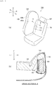
- Fig. 1 is a diagram illustrating a side airbag device 100 according to an embodiment of the present invention.
- the side airbag device 100 and a seat 102 on the vehicle right side at which the side airbag device 100 is used are illustrated from the inside in the vehicle width direction (inside the vehicle).
- the forward and backward directions of the vehicle are indicated by arrows F (Forward) and B (Back)
- the left and right in the vehicle width direction are indicated by arrows L (Left) and R (Right) are indicated by arrows U (up) and D (down), respectively.
- the side airbag device 100 is configured such that the airbag cushion (cushion 104) is inflated and deployed on the side of the seat 102.
- the cushion 104 is a bag-shaped portion that receives the occupant in the event of an emergency, such as when an impact is generated on the vehicle, and the cushion is inflated and deployed in a flat shape between the occupant (not shown) of the seat 102 and a door trim.
- the outer surface of the cushion 104 is constituted by main panels 106 (main panels 106a, 106b).
- the main panels 106 are made of a base cloth and formed into a bag shape by sewing, adhesive bonding, or the like.
- the cushion 104 is wound or folded and stored in a predetermined storage section provided on the side portion of the seatback 108. Since the surface material of the seatback 108 covers the cushion 104 from above in the stored state, the cushion cannot be seen from the outside. When the side airbag device 100 is in operation, the cushion 104 ruptures the surface material 118 ( Fig. 1(b) ), inflates and deploys to the side of the occupant, and restrains the occupant from the side.
- An inflator 110 is a gas generating apparatus which operates upon receiving an operation signal transmitted from the vehicle when an impact occurs, and supplies gas to the interior of the cushion 104.
- the inflator 110 used in the present embodiment is a cylinder-type (cylinder-like) inflator and is installed on the vehicle rear side inside the cushion 104, with the front-back direction of the inflator being oriented in the vertical direction.
- the inflator 110 is provided with a stud bolt 112.
- the stud bolt 112 penetrates the cushion 104 and is fastened to the internal part, or the like, on the side portion of the seatback 108.
- inflators are presently widely used: a type in which a gas generating agent is filled and burned to generate a gas, a type in which compressed gas is filled and a gas is supplied without generating heat, and a hybrid type using both combustion gas and compressed gas.
- An inflator of any type can be used as the inflator 110.
- Fig. 1(b) is a view illustrating the state of the cushion 104 shown in Fig. 1(a) when it is stored.
- Fig. 1(b) corresponds to the A-A cross section of the seatback 108 in Fig. 1(a) .
- the cushion 104 is built in the side portion of the seatback 108 and attached to a metal plate 109 which is an inner member of the seatback 108.
- the vehicle front side and vehicle outer side of the cushion 104 are covered with a surface material 118 such as a urethane 114 and a stay cloth 116.
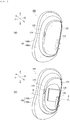
- Fig. 2 is a view showing the inside of the cushion 104 shown in Fig. 1(a) .
- part of the main panel 106a on the vehicle inner side of the cushion 104 is omitted to show the internal configuration of the cushion.
- the cushion 104 has a double structure constituted by a main bag 120 on the outer side and an inner bag 122 on the inner side.
- the main bag 120 and the inner bag 122 are each formed in a bag shape.
- the main bag 120 constitutes an outer shell of the cushion 104, and inflates and deploys from the seat 102 (see Fig. 1(a) ) to the side of the occupant and the vehicle front side.
- the inner bag 122 is a bag-shaped structure independent of the main bag 120 and is provided on the vehicle rear side inside the main bag 120.
- the inner bag 122 encloses the inflator 110, initially receives the gas from the inflator 110, and inflates and deploys before the main bag 120.
- a vent hole 124 is provided in the inner bag 122, and a gas is supplied to the main bag 120 through the vent hole 124 of the inner bag 122.
- a configuration in which the inflator 110 is shared between the inner bag 122 and the main bag 120 as in the present embodiment is advantageous in terms of cost and allows storage in a smaller space.
- the inner bag 122 functions as a pre-push bag (pre-push function).
- pre-push function The inner bag 122 inflates and deploys before the main bag 120 due to detection of impact or advance detection of impact, inflates in the vehicle width direction and quickly acts on the occupant.
- the inner bag 122 pushes the occupant to a certain extent in a direction away from the collision side of the vehicle at the initial stage of deployment. As a result, the impact when the main bag 120 thereafter restrains the occupant is relaxed, and the level of injury of the occupant can be suppressed.
- the cushion 104 of the present embodiment can also reduce the harmfulness to the occupant present in an unexpected posture, for example, other than the regular seating state (so-called out-of-position).
- out-of-position For example, when the occupant is present near the vehicle outer side of the seat, the occupant is positioned on the vehicle front side of the cushion 104, and particularly the main bag 120 of the cushion 104 is in linear contact with the occupant.
- the inner bag 122 initially receives the gas and inflates rapidly in the thickness direction (vehicle width direction) of the cushion 104, the rigidity of the main bag 120 immediately after the operation of the inflator 110 is suppressed and the input load to the out-of-position occupant can be reduced.
- a tension member 126 is provided inside the inner bag 122.
- the tension member 126 pulls the inner bag 122 in the front-back direction of the vehicle.
- a more complete occupant protection is enabled by a simple configuration using the tension member 126.
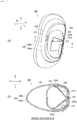
- Fig. 3 is a cross-sectional view of the cushion 104 taken along the line B-B in Fig. 2(b) .
- Fig. 3(a) illustrates the cushion 104 at the time of inflation and deployment.
- the tension member 126 is formed by using a base cloth or the like and spans the inside of the inner bag 122 in the front-back direction of the vehicle between the front end portion 128 of the inner bag 122 on the vehicle front side and a rear end portion 132 of the inner bag which is on the vehicle rear side posterior to the front end portion 128.
- the tension member 126 is tensioned in the front-back direction of the vehicle and pulls the inner bag 122 in the front-back direction of the vehicle.
- the length from the portion of the tension member 126 which is joined to the front end portion 128 to the portion joined to the rear end portion 132 is set shorter than the distance between the front end portion 128 and the rear end portion 132 at the time of inflation when the tension member 126 is not provided.
- the tension member 126 pulls the front end portion 128 and the rear end portion 132 of the inner bag 122 in the front-back direction of the vehicle.
- the length of the inner bag 122 in the front-back direction of the vehicle at the time of inflation is restricted by the tension member 126 to a predetermined range, and the inner bag 122 inflates so as to become thicker in the vehicle width direction by that amount.
- the inner bag 122 has a bag-shaped configuration independent of the main bag 120, and the surface of the base cloth of the inner bag 122 can slide on the inner surface of the base cloth of the main bag 120. Therefore, the inflating main bag 120 produces little effect on the inner bag 122, and the inner bag can inflate and deploy by moving independently of the main bag 120.
- the outer shape of the main bag 120 on the vehicle rear side is affected by the shape of the inner bag 122 at the time of inflation.
- the vehicle rear side of the main bag 120 is pushed and spread from the inside to both sides in the vehicle width direction by the inner bag 122 and inflates to be thicker in the vehicle width direction.
- the thickness of the main bag 120 in the vehicle width direction on the vehicle rear side in the present embodiment is larger than the thickness of the main bag in the vehicle width direction on the vehicle rear side in the conventional configuration which is not provided with the inner bag 122.
- Fig. 3(b) is a view illustrating an initial state of inflation and deployment of the cushion 104 shown in Fig. 3(a) .
- the main bag 120 of the present embodiment has the above-described inner bag 122, so that the thickness of the main bag in the vehicle width direction on the vehicle rear side quickly increases at the initial stage of inflation and deployment. As a result, the above-described pre-push function is realized.
- Fig. 4 is a view illustrating a process in which the cushion 104 shown in Fig. 1(b) is inflated and deployed.
- Fig. 4(a) illustrates the initial stage of inflation and deployment of the cushion 104.
- the thickness of the main bag 120 in the vehicle width direction on the vehicle rear side is rapidly increased by the inner bag 122 before the entire main bag 120 inflates and deploys. Therefore, as a pre-push function, the vehicle rear side of the main bag 120 can push the occupant away from the collision side of the vehicle at an early stage after the detection of the impact and the pre-detection of the impact.
- Fig. 4(b) is a view illustrating the process of inflation and deployment of the cushion 104 following the initial stage shown in Fig. 4(a) .
- the inner bag 122 inflates to be thicker in the vehicle width direction under the effect of the tension member 126, so that the surface material 118 of the seat 102 can be opened more widely. Therefore, not only it is possible to realize advantageously the pre-push function by the inner bag 122, but it is also possible to inflate and deploy the main bag 120 quickly and smoothly into the inner space of the vehicle as shown in Fig. 4(b) .
- the inner bag 122 can be caused to act on the occupant so as to push the occupant at the initial stage of inflation and deployment, thereby ensuring complete occupant protection from an earlier time point after the collision.
- this embodiment is effective in terms of labor and cost as compared to the case where a similar effect is attained by changing the shape of the cushion 104 itself or changing the inflator 110 to be used.
- Fig. 5 is a view illustrating a first modification example of the tension member 126 illustrated in Fig. 2(b) .
- the already described components are assigned with the same reference numerals, and the description thereof is omitted. Even in the case of components assigned with different reference numerals, those having the same names as the already described components are assumed to have the same configuration and function.
- Fig. 5(a) is a view illustrating a tension member 200 corresponding to Fig. 2(b) .
- the tension member 200 is configured of two tethers 202a, 202b formed in a belt shape.
- the tethers 202a, 202b span the inside of the inner bag 122 from the front side to two places on the rear side in the front-back direction of the vehicle.
- Fig. 5(b) is a cross sectional view taken along the line C-C in Fig. 5(a) .
- the tethers 202a, 202b span between one point on a front end portion 128 of the inner bag 122 in the front-back direction of the vehicle and two places, namely, side portions 130a, 130b, on the vehicle rear side posterior to the front end portion 128.
- the tethers 202a, 202b are tensioned as the inner bag 122 inflates and deploys. At this time, the tether 202a pulls the front end portion 128 of the inner bag 122 and the side portion 130a on the vehicle inner side, and the tether 202b pulls the front end portion 128 of the inner bag 122 and the side portion 130b on the vehicle outer side. In this way, since the forces from the two tethers 202a, 202b concentrate at one point of the front end portion 128, the inflation of the front end portion 128 toward the front side of the vehicle is restricted, and the inner bag 122 inflates to a greater thickness in the vehicle width direction.
- the inner bag 122 can also be inflated to a greater thickness in the vehicle width direction and the surface material 118 of the seat 102 (see Fig. 1(b) ) can be opened wider by the tension member 200. Therefore, the pre-push function of the inner bag 122 is improved, and the inner bag 122 can be quickly and smoothly inflated and deployed to the inner space of the vehicle. In this manner, the pre-push function of the inner bag 122 can be improved by the tension member 200 including the plurality of tethers 202a, 202b.
- Fig. 6 is a view illustrating a second modification example of the tension member 126 illustrated in Fig. 2(b) .
- Fig. 6(a) is a view illustrating a tension member 220 corresponding to Fig. 2(b) .
- the tension member 220 is also configured of two tethers 222a, 222b formed in a belt shape.
- the tethers 222a, 222b span the inside of the inner bag 122 from the rear side to two places on the front side in the front-back direction of the vehicle.
- Fig. 6(b) is a cross sectional view taken along the line D-D in Fig. 6(a) .
- the tethers 222a, 222b span between one point on a rear end portion 132 of the inner bag 122 in the front-back direction of the vehicle and two places, namely, side portions 134a, 134b, on the vehicle front side anterior to the rear end portion 132.
- the tethers 222a, 222b are tensioned as the inner bag 122 inflates and deploys. At this time, the tether 222a pulls the rear end portion 132 of the inner bag 122 and the side portion 134a on the vehicle inner side, and the tether 222b pulls the rear end portion 132 of the inner bag 122 and the side portion 134b on the vehicle outer side. In this way, since the forces from the two tethers 222a, 222b concentrate at one point of the rear end portion 132, the inflation of the rear end portion 132 toward the rear side of the vehicle is restricted, and the inner bag 122 inflates to a greater thickness in the vehicle width direction.
- the inner bag 122 can also be inflated to a greater thickness in the vehicle width direction and the surface material 118 of the seat 102 (see Fig. 1(b) ) can be opened wider by the tension member 220. Therefore, the pre-push function of the inner bag 122 is improved, and the inner bag 122 can be quickly and smoothly inflated and deployed to the inner space of the vehicle. In this manner, the pre-push function of the inner bag 122 can be improved by the tension member 220 including the plurality of tethers 222a, 222b.
- the present invention can be applied not only to a side airbag that inflates and deploys between the vehicle door and the passenger, but also to a center airbag that inflates and deploys between seats in the vehicle width direction. Further, the present invention can be applied to the side airbag and center airbag not only for the front seat, but also for the rear seat of the vehicle.
- the present invention can be applied to a side airbag device including a bag-shaped airbag cushion which inflates and deploys toward a side of an occupant on the seat of a vehicle.
Description
- The present invention relates to a side airbag device including a bag-shaped airbag cushion which inflates and deploys toward a side of an occupant of a seat of a vehicle.
- Airbag devices have become almost standard equipment in recent vehicles. An airbag device is a safety device that operates during an emergency such as a vehicle collision, and inflates and deploys an airbag cushion (hereinafter simply referred to as "cushion") with a gas pressure to receive and protect an occupant. Airbag devices come in various types in accordance with installation locations or applications. For example, in order to protect a driver from impact in the front-back direction, a front airbag device is provided at the center of a steering wheel. In addition, in order to protect the occupant from impacts in the vehicle width direction which are caused by a side collision or the like, a curtain airbag device is provided in the vicinity of a ceiling above a side window, and a side airbag device is provided in a side portion of a seat.
- The shape and structure of the airbag cushion are set in consideration of various situations and circumstances. For example, the airbag cushion of the side airbag disclosed in PTL 1 has a double structure including a tube 48 inside an airbag 18. This tube 48 is a part that can be used as a pre-push bag described hereinbelow.
- A pre-push bag (also referred to as pre-crash bag) is a mechanism developed to relieve the impact that can be received by an occupant from the airbag cushion. The pre-push bag has a bag-shaped structure independent of the entire airbag cushion, and is provided on the inner side of the airbag cushion, the occupant side, and the like. The pre-push bag inflates, deploys and comes into contact with the occupant earlier than the entire airbag cushion. The pre-push bag pushes back the occupant to a certain extent in advance, thereby making it possible to relieve the impact when restraining the occupant with the entire airbag cushion and to reduce the level of injury of the occupant (pre-push function)
- PTL 2 discloses a side airbag device according to the preamble of claim 1.
- [PTL 1] Japanese Translation of
PCT Application No. 2010-535121 GB 2 524 292 A - The airbag cushion of the side airbag device is mainly built in the outer side (vehicle outer side) of the seat back in the vehicle width direction, and when an emergency occurs, the airbag cushion ruptures the surface material of the seat back and inflates and deploys in the interior space. An effective method of improving the pre-push function to attain more complete protection of the occupant is to efficiently rupture the surface material of the seat back and cause the pre-push bag to appear in the interior space quickly and smoothly.
- In view of such problems, it is an object of the present invention to provide a side airbag device that enables more complete occupant protection.
- In order to solve the above problem, a typical configuration of a side airbag device according to the present invention includes: a main bag which is formed in a bag shape, is built in a seat of a vehicle, and inflates and deploys toward a side of an occupant and a vehicle front side; an inner bag which is formed in a bag shape independent of the main bag, and inflates and deploys on a vehicle rear side inside the main bag; an inflator which is provided inside the inner bag to supply gas; and a tension member which spans between the vehicle front side and the vehicle rear side inside the inner bag and is tensioned as the inner bag inflates and deploys, wherein a length of the inner bag in a front-back direction of the vehicle at the time of inflation is restricted by the tension member to a predetermined range, and due to the restriction, the inner bag further inflates in a vehicle width direction and pushes and spreads the vehicle rear side of the main bag from the inside of the main bag to both sides in the vehicle width direction.
- With this configuration, the inner bag functions as a pre-push bag, and the inner bag inflates and deploys earlier than the main bag. Since the inflation of the inner bag in the front-back direction of the vehicle is restricted by the tension member, the inner bag further inflates in the vehicle width direction. Therefore, the inner bag opens the surface material of the seat wider, and can inflate and deploy quickly and smoothly to the space inside the vehicle. Thus, according to the above configuration, the inner bag can be efficiently brought into contact with the occupant to push back the occupant, thereby enabling complete occupant protection.
- The tension member may span between a front end portion inside the inner bag and a predetermined position which is on the vehicle rear side posterior to the front end portion.
- With this configuration, since the inflation of the inner bag in the front-back direction of the vehicle is also restricted by the tension member, the inner bag further inflates in the vehicle width direction. Therefore, the inner bag opens the surface material of the seat wider, and can inflate and deploy quickly and smoothly to the space inside the vehicle. Thus, according to the above configuration, the inner bag can be efficiently brought into contact with the occupant to push back the occupant, thereby enabling complete occupant protection.
- The tension member may span between a rear end portion inside the inner bag and a predetermined position which is on the vehicle front side anterior to the rear end portion.
- With this configuration, since the inflation of the inner bag in the front-back direction of the vehicle is also restricted by the tension member, the inner bag further inflates in the vehicle width direction. Therefore, the inner bag opens the surface material of the seat wider, and can inflate and deploy quickly and smoothly to the space inside the vehicle. Thus, according to the above configuration, the inner bag can be efficiently brought into contact with the occupant to push back the occupant, thereby enabling complete occupant protection.
- The tension member may include a plurality of tethers formed in a belt shape, and the plurality of tethers may span the inside of the inner bag from one point on one side in the front-back direction of the vehicle to a plurality of positions on the other side. With this configuration, it is also possible to restrict the inflation of the inner bag in the front-back direction of the vehicle and to inflate the inner bag to a greater thickness in the vehicle width direction.
- According to the present invention, it is possible to provide a side airbag device that enables more complete occupant protection.
-
- [
Fig. 1] Fig. 1 is a view illustrating a side airbag device according to an embodiment of the present invention. - [
Fig. 2] Fig. 2 is a view illustrating the inside of the cushion shown inFig. 1(a) . - [
Fig. 3] Fig. 3 is a cross-sectional view taken along the line B-B of thecushion 104 shown inFig. 2(b) . - [
Fig. 4] Fig. 4 is a view illustrating the process of inflating and deploying thecushion 104 shown inFig. 1(b) . - [
Fig. 5] Fig. 5 is a view illustrating a first modification example of atension member 126 shown inFig. 2(b) . - [
Fig. 6] Fig. 6 is a view illustrating a second modification example of thetension member 126 shown inFig. 2(b) . -
- 100
- Side airbag device
- 102
- Seat
- 104
- Cushion
- 106
- Main panel
- 106a
- Main panel on the vehicle inner side
- 106b
- Main panel on the vehicle outer side
- 108
- Seatback
- 109
- Metal plate
- 110
- Inflator
- 112
- Stud bolt
- 114
- Urethane
- 116
- Stay cloth
- 118
- Surface material
- 120
- Main bag
- 122
- Inner bag
- 124
- Vent hole
- 126
- Tension member
- 128
- Front end portion of the inner bag
- 130a
- Side portion on the vehicle inner side of the inner bag
- 130b
- Side portion on the vehicle outer side of the inner bag
- 132
- Rear end portion of the inner bag
- 134a
- Side portion on the vehicle inner side of the inner bag
- 134b
- Side portion on the vehicle outer side of the inner bag
- 200
- Tension member of the first modification example
- 202a
- Tether on the vehicle inner side
- 202b
- Tether on the vehicle outer side
- 220
- Tension member of the second modification example
- 222a
- Tether on the vehicle inner side
- 222b
- Tether on the vehicle outer side
- Preferred embodiments of the present invention will now be described in detail with reference to the accompanying drawings. The dimensions, materials, and also concrete numerical values and the like shown in such embodiments are merely exemplary and serve to facilitate understanding of the invention, and the present invention is not limited thereto unless otherwise noted. In the specification and the drawings, elements having substantially the same function and configuration are denoted by the same reference numerals, and redundant explanation thereof is omitted. Elements not directly related to the present invention are not shown in the drawings.
-
Fig. 1 is a diagram illustrating aside airbag device 100 according to an embodiment of the present invention. InFig. 1(a) , theside airbag device 100 and aseat 102 on the vehicle right side at which theside airbag device 100 is used are illustrated from the inside in the vehicle width direction (inside the vehicle). InFig. 1(a) and all other drawings of the present application, the forward and backward directions of the vehicle are indicated by arrows F (Forward) and B (Back), the left and right in the vehicle width direction are indicated by arrows L (Left) and R (Right) are indicated by arrows U (up) and D (down), respectively. - As shown in
Fig. 1(a) , theside airbag device 100 is configured such that the airbag cushion (cushion 104) is inflated and deployed on the side of theseat 102. Thecushion 104 is a bag-shaped portion that receives the occupant in the event of an emergency, such as when an impact is generated on the vehicle, and the cushion is inflated and deployed in a flat shape between the occupant (not shown) of theseat 102 and a door trim. - The outer surface of the
cushion 104 is constituted by main panels 106 (main panels main panels 106 are made of a base cloth and formed into a bag shape by sewing, adhesive bonding, or the like. - The
cushion 104 is wound or folded and stored in a predetermined storage section provided on the side portion of theseatback 108. Since the surface material of theseatback 108 covers thecushion 104 from above in the stored state, the cushion cannot be seen from the outside. When theside airbag device 100 is in operation, thecushion 104 ruptures the surface material 118 (Fig. 1(b) ), inflates and deploys to the side of the occupant, and restrains the occupant from the side. - An inflator 110 is a gas generating apparatus which operates upon receiving an operation signal transmitted from the vehicle when an impact occurs, and supplies gas to the interior of the
cushion 104. The inflator 110 used in the present embodiment is a cylinder-type (cylinder-like) inflator and is installed on the vehicle rear side inside thecushion 104, with the front-back direction of the inflator being oriented in the vertical direction. Theinflator 110 is provided with astud bolt 112. Thestud bolt 112 penetrates thecushion 104 and is fastened to the internal part, or the like, on the side portion of theseatback 108. - The following types of inflators are presently widely used: a type in which a gas generating agent is filled and burned to generate a gas, a type in which compressed gas is filled and a gas is supplied without generating heat, and a hybrid type using both combustion gas and compressed gas. An inflator of any type can be used as the
inflator 110. -
Fig. 1(b) is a view illustrating the state of thecushion 104 shown inFig. 1(a) when it is stored.Fig. 1(b) corresponds to the A-A cross section of theseatback 108 inFig. 1(a) . As shown inFig. 1(b) , thecushion 104 is built in the side portion of theseatback 108 and attached to ametal plate 109 which is an inner member of theseatback 108. The vehicle front side and vehicle outer side of thecushion 104 are covered with asurface material 118 such as aurethane 114 and astay cloth 116. -
Fig. 2 is a view showing the inside of thecushion 104 shown inFig. 1(a) . InFig. 2(a) , part of themain panel 106a on the vehicle inner side of thecushion 104 is omitted to show the internal configuration of the cushion. - The
cushion 104 has a double structure constituted by amain bag 120 on the outer side and aninner bag 122 on the inner side. Themain bag 120 and theinner bag 122 are each formed in a bag shape. - The
main bag 120 constitutes an outer shell of thecushion 104, and inflates and deploys from the seat 102 (seeFig. 1(a) ) to the side of the occupant and the vehicle front side. - The
inner bag 122 is a bag-shaped structure independent of themain bag 120 and is provided on the vehicle rear side inside themain bag 120. Theinner bag 122 encloses the inflator 110, initially receives the gas from theinflator 110, and inflates and deploys before themain bag 120. - A
vent hole 124 is provided in theinner bag 122, and a gas is supplied to themain bag 120 through thevent hole 124 of theinner bag 122. Although it is possible to provide separate inflators for theinner bag 122 and themain bag 120, a configuration in which theinflator 110 is shared between theinner bag 122 and themain bag 120 as in the present embodiment is advantageous in terms of cost and allows storage in a smaller space. - The
inner bag 122 functions as a pre-push bag (pre-push function). Theinner bag 122 inflates and deploys before themain bag 120 due to detection of impact or advance detection of impact, inflates in the vehicle width direction and quickly acts on the occupant. Theinner bag 122 pushes the occupant to a certain extent in a direction away from the collision side of the vehicle at the initial stage of deployment. As a result, the impact when themain bag 120 thereafter restrains the occupant is relaxed, and the level of injury of the occupant can be suppressed. - The
cushion 104 of the present embodiment can also reduce the harmfulness to the occupant present in an unexpected posture, for example, other than the regular seating state (so-called out-of-position). For example, when the occupant is present near the vehicle outer side of the seat, the occupant is positioned on the vehicle front side of thecushion 104, and particularly themain bag 120 of thecushion 104 is in linear contact with the occupant. However, as theinner bag 122 initially receives the gas and inflates rapidly in the thickness direction (vehicle width direction) of thecushion 104, the rigidity of themain bag 120 immediately after the operation of theinflator 110 is suppressed and the input load to the out-of-position occupant can be reduced. - In
Fig. 2(b) , part of theinner bag 122 ofFig. 2(a) on the vehicle inner side is omitted to show the internal structure thereof. In the present embodiment, atension member 126 is provided inside theinner bag 122. Thetension member 126 pulls theinner bag 122 in the front-back direction of the vehicle. In the present embodiment, a more complete occupant protection is enabled by a simple configuration using thetension member 126. -
Fig. 3 is a cross-sectional view of thecushion 104 taken along the line B-B inFig. 2(b) . Similarly toFig. 2(b) ,Fig. 3(a) illustrates thecushion 104 at the time of inflation and deployment. Thetension member 126 is formed by using a base cloth or the like and spans the inside of theinner bag 122 in the front-back direction of the vehicle between thefront end portion 128 of theinner bag 122 on the vehicle front side and arear end portion 132 of the inner bag which is on the vehicle rear side posterior to thefront end portion 128. - As the
inner bag 122 inflates and deploys, thetension member 126 is tensioned in the front-back direction of the vehicle and pulls theinner bag 122 in the front-back direction of the vehicle. In other words, the length from the portion of thetension member 126 which is joined to thefront end portion 128 to the portion joined to therear end portion 132 is set shorter than the distance between thefront end portion 128 and therear end portion 132 at the time of inflation when thetension member 126 is not provided. - With the abovementioned configuration, the
tension member 126 pulls thefront end portion 128 and therear end portion 132 of theinner bag 122 in the front-back direction of the vehicle. The length of theinner bag 122 in the front-back direction of the vehicle at the time of inflation is restricted by thetension member 126 to a predetermined range, and theinner bag 122 inflates so as to become thicker in the vehicle width direction by that amount. - The
inner bag 122 has a bag-shaped configuration independent of themain bag 120, and the surface of the base cloth of theinner bag 122 can slide on the inner surface of the base cloth of themain bag 120. Therefore, the inflatingmain bag 120 produces little effect on theinner bag 122, and the inner bag can inflate and deploy by moving independently of themain bag 120. - The outer shape of the
main bag 120 on the vehicle rear side is affected by the shape of theinner bag 122 at the time of inflation. The vehicle rear side of themain bag 120 is pushed and spread from the inside to both sides in the vehicle width direction by theinner bag 122 and inflates to be thicker in the vehicle width direction. The thickness of themain bag 120 in the vehicle width direction on the vehicle rear side in the present embodiment is larger than the thickness of the main bag in the vehicle width direction on the vehicle rear side in the conventional configuration which is not provided with theinner bag 122. -
Fig. 3(b) is a view illustrating an initial state of inflation and deployment of thecushion 104 shown inFig. 3(a) . Themain bag 120 of the present embodiment has the above-describedinner bag 122, so that the thickness of the main bag in the vehicle width direction on the vehicle rear side quickly increases at the initial stage of inflation and deployment. As a result, the above-described pre-push function is realized. -
Fig. 4 is a view illustrating a process in which thecushion 104 shown inFig. 1(b) is inflated and deployed.Fig. 4(a) illustrates the initial stage of inflation and deployment of thecushion 104. As shown inFig. 4(a) , the thickness of themain bag 120 in the vehicle width direction on the vehicle rear side is rapidly increased by theinner bag 122 before the entiremain bag 120 inflates and deploys. Therefore, as a pre-push function, the vehicle rear side of themain bag 120 can push the occupant away from the collision side of the vehicle at an early stage after the detection of the impact and the pre-detection of the impact. -
Fig. 4(b) is a view illustrating the process of inflation and deployment of thecushion 104 following the initial stage shown inFig. 4(a) . At the initial stage of inflation and deployment shown inFig. 4(a) , theinner bag 122 inflates to be thicker in the vehicle width direction under the effect of thetension member 126, so that thesurface material 118 of theseat 102 can be opened more widely. Therefore, not only it is possible to realize advantageously the pre-push function by theinner bag 122, but it is also possible to inflate and deploy themain bag 120 quickly and smoothly into the inner space of the vehicle as shown inFig. 4(b) . - As described above, according to the present embodiment, the
inner bag 122 can be caused to act on the occupant so as to push the occupant at the initial stage of inflation and deployment, thereby ensuring complete occupant protection from an earlier time point after the collision. In addition, since the occupant protection performance is improved with a simple configuration using thetension member 126, this embodiment is effective in terms of labor and cost as compared to the case where a similar effect is attained by changing the shape of thecushion 104 itself or changing the inflator 110 to be used. -
Fig. 5 is a view illustrating a first modification example of thetension member 126 illustrated inFig. 2(b) . In the following description, the already described components are assigned with the same reference numerals, and the description thereof is omitted. Even in the case of components assigned with different reference numerals, those having the same names as the already described components are assumed to have the same configuration and function. -
Fig. 5(a) is a view illustrating atension member 200 corresponding toFig. 2(b) . Thetension member 200 is configured of twotethers tethers inner bag 122 from the front side to two places on the rear side in the front-back direction of the vehicle. -
Fig. 5(b) is a cross sectional view taken along the line C-C inFig. 5(a) . Thetethers front end portion 128 of theinner bag 122 in the front-back direction of the vehicle and two places, namely,side portions front end portion 128. - The
tethers inner bag 122 inflates and deploys. At this time, thetether 202a pulls thefront end portion 128 of theinner bag 122 and theside portion 130a on the vehicle inner side, and thetether 202b pulls thefront end portion 128 of theinner bag 122 and theside portion 130b on the vehicle outer side. In this way, since the forces from the twotethers front end portion 128, the inflation of thefront end portion 128 toward the front side of the vehicle is restricted, and theinner bag 122 inflates to a greater thickness in the vehicle width direction. - The
inner bag 122 can also be inflated to a greater thickness in the vehicle width direction and thesurface material 118 of the seat 102 (seeFig. 1(b) ) can be opened wider by thetension member 200. Therefore, the pre-push function of theinner bag 122 is improved, and theinner bag 122 can be quickly and smoothly inflated and deployed to the inner space of the vehicle. In this manner, the pre-push function of theinner bag 122 can be improved by thetension member 200 including the plurality oftethers -
Fig. 6 is a view illustrating a second modification example of thetension member 126 illustrated inFig. 2(b) .Fig. 6(a) is a view illustrating atension member 220 corresponding toFig. 2(b) . Thetension member 220 is also configured of twotethers tethers inner bag 122 from the rear side to two places on the front side in the front-back direction of the vehicle. -
Fig. 6(b) is a cross sectional view taken along the line D-D inFig. 6(a) . Thetethers rear end portion 132 of theinner bag 122 in the front-back direction of the vehicle and two places, namely,side portions rear end portion 132. - The
tethers inner bag 122 inflates and deploys. At this time, thetether 222a pulls therear end portion 132 of theinner bag 122 and theside portion 134a on the vehicle inner side, and thetether 222b pulls therear end portion 132 of theinner bag 122 and theside portion 134b on the vehicle outer side. In this way, since the forces from the twotethers rear end portion 132, the inflation of therear end portion 132 toward the rear side of the vehicle is restricted, and theinner bag 122 inflates to a greater thickness in the vehicle width direction. - The
inner bag 122 can also be inflated to a greater thickness in the vehicle width direction and thesurface material 118 of the seat 102 (seeFig. 1(b) ) can be opened wider by thetension member 220. Therefore, the pre-push function of theinner bag 122 is improved, and theinner bag 122 can be quickly and smoothly inflated and deployed to the inner space of the vehicle. In this manner, the pre-push function of theinner bag 122 can be improved by thetension member 220 including the plurality oftethers - Although the preferred embodiments of the present invention have been described above with reference to the accompanying drawings, the above-described embodiments are preferred examples of the present invention, and other embodiments can also be implemented or accomplished by various methods. Unless otherwise specified in the description of the present application, the present invention is not limited by the detailed shape, size, mutual arrangement, etc. of the parts shown in the accompanying drawings. Also, the expressions and terms used in the description of the present application are for the purpose of explanation, and are not limiting, unless there is a description of a particularly restricted subject matter. For example, the present invention can be applied not only to a side airbag that inflates and deploys between the vehicle door and the passenger, but also to a center airbag that inflates and deploys between seats in the vehicle width direction. Further, the present invention can be applied to the side airbag and center airbag not only for the front seat, but also for the rear seat of the vehicle.
- The present invention can be applied to a side airbag device including a bag-shaped airbag cushion which inflates and deploys toward a side of an occupant on the seat of a vehicle.
Claims (4)
- A side airbag device (100) comprising:a main bag (120) which is formed in a bag shape, is built in a seat (102) of a vehicle, and inflates and deploys toward a side of an occupant and a vehicle front side;an inner bag (122) which is formed in a bag shape independent of the main bag (120), and inflates and deploys on a vehicle rear side inside the main bag (120);an inflator (110) which is provided inside the inner bag (122) to supply gas;characterized bya tension member (126) which spans between the vehicle front side and the vehicle rear side inside the inner bag (122) and is tensioned as the inner bag (122) inflates and deploys, whereina length of the inner bag (122) in a front-back direction of the vehicle at the time of inflation is restricted by the tension member (126) to a predetermined range, and due to the restriction, the inner bag (122) further inflates in a vehicle width direction and pushes and spreads the vehicle rear side of the main bag (120) from the inside of the main bag (120) to both sides in the vehicle width direction.
- The side airbag device (100) according to claim 1, wherein the tension member (126) spans between a front end portion inside the inner bag (122) and a predetermined position which is on the vehicle rear side posterior to the front end portion.
- The side airbag device (100) according to claim 1, wherein the tension member (126) spans between a rear end portion inside the inner bag and a predetermined position which is on the vehicle front side anterior to the rear end portion.
- The side airbag device (100) according to any one of claims 1 to 3, wherein the tension member (126) includes a plurality of tethers formed in a belt shape, and the plurality of tethers spans the inside of the inner bag (122) from one point on one side in the front-back direction of the vehicle to a plurality of positions on the other side.
Applications Claiming Priority (2)
| Application Number | Priority Date | Filing Date | Title |
|---|---|---|---|
| JP2015190770 | 2015-09-29 | ||
| PCT/JP2016/077522 WO2017057073A1 (en) | 2015-09-29 | 2016-09-16 | Side airbag device |
Publications (3)
| Publication Number | Publication Date |
|---|---|
| EP3357765A1 EP3357765A1 (en) | 2018-08-08 |
| EP3357765A4 EP3357765A4 (en) | 2019-03-27 |
| EP3357765B1 true EP3357765B1 (en) | 2020-02-05 |
Family
ID=58423650
Family Applications (1)
| Application Number | Title | Priority Date | Filing Date |
|---|---|---|---|
| EP16851247.3A Active EP3357765B1 (en) | 2015-09-29 | 2016-09-16 | Side airbag device |
Country Status (5)
| Country | Link |
|---|---|
| US (1) | US10518738B2 (en) |
| EP (1) | EP3357765B1 (en) |
| JP (1) | JP6430652B2 (en) |
| CN (1) | CN108136991B (en) |
| WO (1) | WO2017057073A1 (en) |
Families Citing this family (11)
| Publication number | Priority date | Publication date | Assignee | Title |
|---|---|---|---|---|
| BR112018000398A2 (en) * | 2015-07-07 | 2018-09-11 | Toyota Boshoku America Inc | error proof brackets for seat upholstery cover airbag strap installation for a seat frame |
| US10518738B2 (en) * | 2015-09-29 | 2019-12-31 | Autoliv Development Ab | Side airbag device |
| JP2017074850A (en) * | 2015-10-14 | 2017-04-20 | 三菱自動車工業株式会社 | Side airbag device |
| US10981533B2 (en) * | 2016-05-20 | 2021-04-20 | Autoliv Development Ab | Side airbag device |
| JP6540647B2 (en) * | 2016-10-07 | 2019-07-10 | トヨタ自動車株式会社 | Curtain airbag system for vehicles |
| JP6537197B2 (en) * | 2017-03-31 | 2019-07-03 | 株式会社Subaru | Curtain airbag |
| KR102387636B1 (en) * | 2017-08-01 | 2022-04-18 | 아우토리브 디벨롭먼트 아베 | occupant protection |
| DE102017217499A1 (en) * | 2017-09-29 | 2019-04-04 | Joyson Safety Systems Germany Gmbh | Airbag unit for a motor vehicle |
| CN110116700B (en) * | 2018-02-06 | 2021-11-16 | 马自达汽车株式会社 | Side airbag device |
| EP3868613A4 (en) * | 2018-10-16 | 2022-07-20 | Autoliv Development AB | Vehicle occupant rerstraining device |
| US11059442B2 (en) * | 2019-03-26 | 2021-07-13 | Trw Vehicle Safety Systems Inc. | Adaptive side airbag for protecting occupants in a vehicle |
Family Cites Families (15)
| Publication number | Priority date | Publication date | Assignee | Title |
|---|---|---|---|---|
| CN100439157C (en) * | 2004-03-30 | 2008-12-03 | 关键安全体系股份有限公司 | Side airbag module |
| JP4720753B2 (en) * | 2007-02-16 | 2011-07-13 | トヨタ自動車株式会社 | Side airbag device |
| WO2008122346A1 (en) * | 2007-04-09 | 2008-10-16 | Autoliv Development Ab | Airbag for protection of a vehicle occupant |
| DE102007026467B4 (en) * | 2007-06-05 | 2010-08-19 | Autoliv Development Ab | Side airbag with a arranged in an outer airbag Second inner airbag |
| JP5359748B2 (en) * | 2009-09-30 | 2013-12-04 | 豊田合成株式会社 | Airbag device |
| KR101075427B1 (en) * | 2009-10-07 | 2011-10-24 | 아우토리브 디벨롭먼트 아베 | Side air bag cushion and production method thereof |
| JP5615097B2 (en) * | 2010-08-26 | 2014-10-29 | 日本プラスト株式会社 | Airbag device for automobile |
| EP2810831B1 (en) | 2012-02-01 | 2018-05-09 | Toyota Jidosha Kabushiki Kaisha | Vehicle side airbag device |
| JP5664607B2 (en) * | 2012-08-02 | 2015-02-04 | トヨタ自動車株式会社 | Side airbag device for vehicle |
| GB2508005B (en) * | 2012-11-16 | 2018-07-18 | Ford Global Tech Llc | Bag-in-bag safety restraint with directional inflation |
| JP5776733B2 (en) * | 2013-07-03 | 2015-09-09 | トヨタ自動車株式会社 | Side airbag device for vehicle |
| GB2524292A (en) * | 2014-03-19 | 2015-09-23 | Ford Global Tech Llc | An airbag system |
| CN204184303U (en) * | 2014-09-30 | 2015-03-04 | 浙江吉利控股集团有限公司 | A kind of side airbag of automobile |
| JP6149840B2 (en) | 2014-10-21 | 2017-06-21 | トヨタ自動車株式会社 | Far-side airbag device for vehicles |
| US10518738B2 (en) * | 2015-09-29 | 2019-12-31 | Autoliv Development Ab | Side airbag device |
-
2016
- 2016-09-16 US US15/762,341 patent/US10518738B2/en active Active
- 2016-09-16 WO PCT/JP2016/077522 patent/WO2017057073A1/en active Application Filing
- 2016-09-16 CN CN201680054948.2A patent/CN108136991B/en active Active
- 2016-09-16 EP EP16851247.3A patent/EP3357765B1/en active Active
- 2016-09-16 JP JP2017543155A patent/JP6430652B2/en active Active
Non-Patent Citations (1)
| Title |
|---|
| None * |
Also Published As
| Publication number | Publication date |
|---|---|
| JPWO2017057073A1 (en) | 2018-04-26 |
| EP3357765A4 (en) | 2019-03-27 |
| CN108136991B (en) | 2020-06-09 |
| US20180297549A1 (en) | 2018-10-18 |
| JP6430652B2 (en) | 2018-11-28 |
| WO2017057073A1 (en) | 2017-04-06 |
| EP3357765A1 (en) | 2018-08-08 |
| US10518738B2 (en) | 2019-12-31 |
| CN108136991A (en) | 2018-06-08 |
Similar Documents
| Publication | Publication Date | Title |
|---|---|---|
| EP3357765B1 (en) | Side airbag device | |
| US10668887B2 (en) | Vehicle seat with side airbag device | |
| US8047564B2 (en) | Airbag | |
| JP6394657B2 (en) | Vehicle occupant restraint system | |
| JP5595154B2 (en) | Curtain airbag | |
| KR20180132822A (en) | Riding protection device | |
| JP5639263B2 (en) | Curtain airbag device for vehicle | |
| JP6097381B2 (en) | Side airbag module for vehicles | |
| EP3696030A1 (en) | Airbag device, method for manufacturing airbag device, and method for deploying airbag device | |
| WO2018105324A1 (en) | Side air bag device | |
| KR102257441B1 (en) | Passenger protection device | |
| CN109963754B (en) | Side airbag device | |
| JP2005527413A (en) | Low profile airbag module design for overhead use | |
| KR102233208B1 (en) | Side Airbag With Internal Diffuser | |
| EP3549831B1 (en) | Side air bag device | |
| EP3741629A1 (en) | Airbag device | |
| KR20090117643A (en) | Vehicle occupant protection system | |
| WO2019138954A1 (en) | Occupant protection apparatus | |
| KR20220100036A (en) | side airbag device | |
| US10518734B2 (en) | Side airbag device | |
| JP6247251B2 (en) | Side airbag device | |
| JP6185653B2 (en) | Curtain airbag device | |
| KR101360437B1 (en) | Air bag cushion module for curtain air bag device | |
| JP6372041B2 (en) | Side airbag device | |
| US20080084049A1 (en) | Integral cushion roll retainer |
Legal Events
| Date | Code | Title | Description |
|---|---|---|---|
| STAA | Information on the status of an ep patent application or granted ep patent |
Free format text: STATUS: THE INTERNATIONAL PUBLICATION HAS BEEN MADE |
|
| PUAI | Public reference made under article 153(3) epc to a published international application that has entered the european phase |
Free format text: ORIGINAL CODE: 0009012 |
|
| STAA | Information on the status of an ep patent application or granted ep patent |
Free format text: STATUS: REQUEST FOR EXAMINATION WAS MADE |
|
| 17P | Request for examination filed |
Effective date: 20180419 |
|
| AK | Designated contracting states |
Kind code of ref document: A1 Designated state(s): AL AT BE BG CH CY CZ DE DK EE ES FI FR GB GR HR HU IE IS IT LI LT LU LV MC MK MT NL NO PL PT RO RS SE SI SK SM TR |
|
| AX | Request for extension of the european patent |
Extension state: BA ME |
|
| DAV | Request for validation of the european patent (deleted) | ||
| DAX | Request for extension of the european patent (deleted) | ||
| A4 | Supplementary search report drawn up and despatched |
Effective date: 20190227 |
|
| RIC1 | Information provided on ipc code assigned before grant |
Ipc: B60R 21/2338 20110101AFI20190221BHEP Ipc: B60R 21/207 20060101ALI20190221BHEP Ipc: B60R 21/231 20110101ALI20190221BHEP |
|
| GRAP | Despatch of communication of intention to grant a patent |
Free format text: ORIGINAL CODE: EPIDOSNIGR1 |
|
| STAA | Information on the status of an ep patent application or granted ep patent |
Free format text: STATUS: GRANT OF PATENT IS INTENDED |
|
| INTG | Intention to grant announced |
Effective date: 20190822 |
|
| GRAS | Grant fee paid |
Free format text: ORIGINAL CODE: EPIDOSNIGR3 |
|
| GRAA | (expected) grant |
Free format text: ORIGINAL CODE: 0009210 |
|
| STAA | Information on the status of an ep patent application or granted ep patent |
Free format text: STATUS: THE PATENT HAS BEEN GRANTED |
|
| AK | Designated contracting states |
Kind code of ref document: B1 Designated state(s): AL AT BE BG CH CY CZ DE DK EE ES FI FR GB GR HR HU IE IS IT LI LT LU LV MC MK MT NL NO PL PT RO RS SE SI SK SM TR |
|
| REG | Reference to a national code |
Ref country code: GB Ref legal event code: FG4D |
|
| REG | Reference to a national code |
Ref country code: AT Ref legal event code: REF Ref document number: 1229679 Country of ref document: AT Kind code of ref document: T Effective date: 20200215 |
|
| REG | Reference to a national code |
Ref country code: DE Ref legal event code: R096 Ref document number: 602016029288 Country of ref document: DE |
|
| REG | Reference to a national code |
Ref country code: IE Ref legal event code: FG4D |
|
| REG | Reference to a national code |
Ref country code: CH Ref legal event code: EP |
|
| REG | Reference to a national code |
Ref country code: NL Ref legal event code: MP Effective date: 20200205 |
|
| PG25 | Lapsed in a contracting state [announced via postgrant information from national office to epo] |
Ref country code: PT Free format text: LAPSE BECAUSE OF FAILURE TO SUBMIT A TRANSLATION OF THE DESCRIPTION OR TO PAY THE FEE WITHIN THE PRESCRIBED TIME-LIMIT Effective date: 20200628 Ref country code: NO Free format text: LAPSE BECAUSE OF FAILURE TO SUBMIT A TRANSLATION OF THE DESCRIPTION OR TO PAY THE FEE WITHIN THE PRESCRIBED TIME-LIMIT Effective date: 20200505 Ref country code: FI Free format text: LAPSE BECAUSE OF FAILURE TO SUBMIT A TRANSLATION OF THE DESCRIPTION OR TO PAY THE FEE WITHIN THE PRESCRIBED TIME-LIMIT Effective date: 20200205 Ref country code: RS Free format text: LAPSE BECAUSE OF FAILURE TO SUBMIT A TRANSLATION OF THE DESCRIPTION OR TO PAY THE FEE WITHIN THE PRESCRIBED TIME-LIMIT Effective date: 20200205 |
|
| REG | Reference to a national code |
Ref country code: LT Ref legal event code: MG4D |
|
| PG25 | Lapsed in a contracting state [announced via postgrant information from national office to epo] |
Ref country code: GR Free format text: LAPSE BECAUSE OF FAILURE TO SUBMIT A TRANSLATION OF THE DESCRIPTION OR TO PAY THE FEE WITHIN THE PRESCRIBED TIME-LIMIT Effective date: 20200506 Ref country code: IS Free format text: LAPSE BECAUSE OF FAILURE TO SUBMIT A TRANSLATION OF THE DESCRIPTION OR TO PAY THE FEE WITHIN THE PRESCRIBED TIME-LIMIT Effective date: 20200605 Ref country code: BG Free format text: LAPSE BECAUSE OF FAILURE TO SUBMIT A TRANSLATION OF THE DESCRIPTION OR TO PAY THE FEE WITHIN THE PRESCRIBED TIME-LIMIT Effective date: 20200505 Ref country code: SE Free format text: LAPSE BECAUSE OF FAILURE TO SUBMIT A TRANSLATION OF THE DESCRIPTION OR TO PAY THE FEE WITHIN THE PRESCRIBED TIME-LIMIT Effective date: 20200205 Ref country code: LV Free format text: LAPSE BECAUSE OF FAILURE TO SUBMIT A TRANSLATION OF THE DESCRIPTION OR TO PAY THE FEE WITHIN THE PRESCRIBED TIME-LIMIT Effective date: 20200205 Ref country code: HR Free format text: LAPSE BECAUSE OF FAILURE TO SUBMIT A TRANSLATION OF THE DESCRIPTION OR TO PAY THE FEE WITHIN THE PRESCRIBED TIME-LIMIT Effective date: 20200205 |
|
| PG25 | Lapsed in a contracting state [announced via postgrant information from national office to epo] |
Ref country code: NL Free format text: LAPSE BECAUSE OF FAILURE TO SUBMIT A TRANSLATION OF THE DESCRIPTION OR TO PAY THE FEE WITHIN THE PRESCRIBED TIME-LIMIT Effective date: 20200205 |
|
| PG25 | Lapsed in a contracting state [announced via postgrant information from national office to epo] |
Ref country code: ES Free format text: LAPSE BECAUSE OF FAILURE TO SUBMIT A TRANSLATION OF THE DESCRIPTION OR TO PAY THE FEE WITHIN THE PRESCRIBED TIME-LIMIT Effective date: 20200205 Ref country code: DK Free format text: LAPSE BECAUSE OF FAILURE TO SUBMIT A TRANSLATION OF THE DESCRIPTION OR TO PAY THE FEE WITHIN THE PRESCRIBED TIME-LIMIT Effective date: 20200205 Ref country code: SK Free format text: LAPSE BECAUSE OF FAILURE TO SUBMIT A TRANSLATION OF THE DESCRIPTION OR TO PAY THE FEE WITHIN THE PRESCRIBED TIME-LIMIT Effective date: 20200205 Ref country code: SM Free format text: LAPSE BECAUSE OF FAILURE TO SUBMIT A TRANSLATION OF THE DESCRIPTION OR TO PAY THE FEE WITHIN THE PRESCRIBED TIME-LIMIT Effective date: 20200205 Ref country code: CZ Free format text: LAPSE BECAUSE OF FAILURE TO SUBMIT A TRANSLATION OF THE DESCRIPTION OR TO PAY THE FEE WITHIN THE PRESCRIBED TIME-LIMIT Effective date: 20200205 Ref country code: EE Free format text: LAPSE BECAUSE OF FAILURE TO SUBMIT A TRANSLATION OF THE DESCRIPTION OR TO PAY THE FEE WITHIN THE PRESCRIBED TIME-LIMIT Effective date: 20200205 Ref country code: LT Free format text: LAPSE BECAUSE OF FAILURE TO SUBMIT A TRANSLATION OF THE DESCRIPTION OR TO PAY THE FEE WITHIN THE PRESCRIBED TIME-LIMIT Effective date: 20200205 Ref country code: RO Free format text: LAPSE BECAUSE OF FAILURE TO SUBMIT A TRANSLATION OF THE DESCRIPTION OR TO PAY THE FEE WITHIN THE PRESCRIBED TIME-LIMIT Effective date: 20200205 |
|
| REG | Reference to a national code |
Ref country code: DE Ref legal event code: R097 Ref document number: 602016029288 Country of ref document: DE |
|
| REG | Reference to a national code |
Ref country code: AT Ref legal event code: MK05 Ref document number: 1229679 Country of ref document: AT Kind code of ref document: T Effective date: 20200205 |
|
| PLBE | No opposition filed within time limit |
Free format text: ORIGINAL CODE: 0009261 |
|
| STAA | Information on the status of an ep patent application or granted ep patent |
Free format text: STATUS: NO OPPOSITION FILED WITHIN TIME LIMIT |
|
| 26N | No opposition filed |
Effective date: 20201106 |
|
| PG25 | Lapsed in a contracting state [announced via postgrant information from national office to epo] |
Ref country code: IT Free format text: LAPSE BECAUSE OF FAILURE TO SUBMIT A TRANSLATION OF THE DESCRIPTION OR TO PAY THE FEE WITHIN THE PRESCRIBED TIME-LIMIT Effective date: 20200205 Ref country code: AT Free format text: LAPSE BECAUSE OF FAILURE TO SUBMIT A TRANSLATION OF THE DESCRIPTION OR TO PAY THE FEE WITHIN THE PRESCRIBED TIME-LIMIT Effective date: 20200205 |
|
| PG25 | Lapsed in a contracting state [announced via postgrant information from national office to epo] |
Ref country code: PL Free format text: LAPSE BECAUSE OF FAILURE TO SUBMIT A TRANSLATION OF THE DESCRIPTION OR TO PAY THE FEE WITHIN THE PRESCRIBED TIME-LIMIT Effective date: 20200205 Ref country code: SI Free format text: LAPSE BECAUSE OF FAILURE TO SUBMIT A TRANSLATION OF THE DESCRIPTION OR TO PAY THE FEE WITHIN THE PRESCRIBED TIME-LIMIT Effective date: 20200205 |
|
| REG | Reference to a national code |
Ref country code: CH Ref legal event code: PL |
|
| REG | Reference to a national code |
Ref country code: BE Ref legal event code: MM Effective date: 20200930 |
|
| PG25 | Lapsed in a contracting state [announced via postgrant information from national office to epo] |
Ref country code: LU Free format text: LAPSE BECAUSE OF NON-PAYMENT OF DUE FEES Effective date: 20200916 |
|
| PG25 | Lapsed in a contracting state [announced via postgrant information from national office to epo] |
Ref country code: BE Free format text: LAPSE BECAUSE OF NON-PAYMENT OF DUE FEES Effective date: 20200930 Ref country code: CH Free format text: LAPSE BECAUSE OF NON-PAYMENT OF DUE FEES Effective date: 20200930 Ref country code: LI Free format text: LAPSE BECAUSE OF NON-PAYMENT OF DUE FEES Effective date: 20200930 Ref country code: IE Free format text: LAPSE BECAUSE OF NON-PAYMENT OF DUE FEES Effective date: 20200916 |
|
| PG25 | Lapsed in a contracting state [announced via postgrant information from national office to epo] |
Ref country code: TR Free format text: LAPSE BECAUSE OF FAILURE TO SUBMIT A TRANSLATION OF THE DESCRIPTION OR TO PAY THE FEE WITHIN THE PRESCRIBED TIME-LIMIT Effective date: 20200205 Ref country code: MT Free format text: LAPSE BECAUSE OF FAILURE TO SUBMIT A TRANSLATION OF THE DESCRIPTION OR TO PAY THE FEE WITHIN THE PRESCRIBED TIME-LIMIT Effective date: 20200205 Ref country code: CY Free format text: LAPSE BECAUSE OF FAILURE TO SUBMIT A TRANSLATION OF THE DESCRIPTION OR TO PAY THE FEE WITHIN THE PRESCRIBED TIME-LIMIT Effective date: 20200205 |
|
| PG25 | Lapsed in a contracting state [announced via postgrant information from national office to epo] |
Ref country code: MK Free format text: LAPSE BECAUSE OF FAILURE TO SUBMIT A TRANSLATION OF THE DESCRIPTION OR TO PAY THE FEE WITHIN THE PRESCRIBED TIME-LIMIT Effective date: 20200205 Ref country code: MC Free format text: LAPSE BECAUSE OF FAILURE TO SUBMIT A TRANSLATION OF THE DESCRIPTION OR TO PAY THE FEE WITHIN THE PRESCRIBED TIME-LIMIT Effective date: 20200205 Ref country code: AL Free format text: LAPSE BECAUSE OF FAILURE TO SUBMIT A TRANSLATION OF THE DESCRIPTION OR TO PAY THE FEE WITHIN THE PRESCRIBED TIME-LIMIT Effective date: 20200205 |
|
| P01 | Opt-out of the competence of the unified patent court (upc) registered |
Effective date: 20230507 |
|
| PGFP | Annual fee paid to national office [announced via postgrant information from national office to epo] |
Ref country code: GB Payment date: 20230926 Year of fee payment: 8 |
|
| PGFP | Annual fee paid to national office [announced via postgrant information from national office to epo] |
Ref country code: FR Payment date: 20230926 Year of fee payment: 8 Ref country code: DE Payment date: 20230928 Year of fee payment: 8 |