JP5595154B2 - Curtain airbag - Google Patents
Curtain airbag Download PDFInfo
- Publication number
- JP5595154B2 JP5595154B2 JP2010162345A JP2010162345A JP5595154B2 JP 5595154 B2 JP5595154 B2 JP 5595154B2 JP 2010162345 A JP2010162345 A JP 2010162345A JP 2010162345 A JP2010162345 A JP 2010162345A JP 5595154 B2 JP5595154 B2 JP 5595154B2
- Authority
- JP
- Japan
- Prior art keywords
- vehicle
- strap
- curtain airbag
- chamber
- airbag
- Prior art date
- Legal status (The legal status is an assumption and is not a legal conclusion. Google has not performed a legal analysis and makes no representation as to the accuracy of the status listed.)
- Active
Links
Images


Description
本発明は、車両の側面衝突時やロールオーバ(横転)時に、乗員保護を目的として車両室内の側面部に沿って膨張展開するカーテンエアバッグに関するものである。 The present invention relates to a curtain airbag that inflates and deploys along a side surface in a vehicle compartment for the purpose of protecting an occupant during a vehicle side collision or rollover (rollover).
カーテンエアバッグはドア上方に設置されていて、車両の側面部に沿って膨張展開して乗員の頭部および上半身からの荷重を吸収する。カーテンエアバッグは主に側面衝突時に乗員を保護(拘束)するよう設計されている。例えば、カーテンエアバッグは膨張展開した際の圧力持続時間がフロントエアバッグ等よりも長くなっている。側面衝突はロールオーバ(横転)を招くおそれがあり、衝撃が発生し得る時間が長いからである。特にロールオーバ時には、乗員がサイドウィンドウから車外に放出される危険性が高まる。そのためカーテンエアバッグは、ロールオーバ時にまで膨張状態を維持することで、乗員を拘束して車外放出防止を図っている。 The curtain airbag is installed above the door and inflates and deploys along the side of the vehicle to absorb the load from the head and upper body of the occupant. Curtain airbags are primarily designed to protect (restrain) occupants during side collisions. For example, a curtain airbag has a longer pressure duration when inflated and deployed than a front airbag or the like. This is because the side collision may cause rollover (rollover), and the time during which an impact may occur is long. In particular, at the time of rollover, there is an increased risk that the occupant is released from the side window to the outside of the vehicle. Therefore, the curtain airbag maintains the inflated state until the rollover, thereby restraining the occupant and preventing release from the vehicle.
カーテンエアバッグには、乗員からの荷重を吸収してその車外放出防止を達成するために、車両側面部への確実な膨張展開が求められている。そこで、例えば特許文献1に記載のカーテンエアバッグは、エアバッグ本体の前端を車両側面部のフロントピラーに連結するストラップを備えている。特許文献1によれば、ストラップがカーテンエアバッグに十分な張力を与えるため、膨張展開したカーテンエアバッグを安定して支持可能であるとされている。
The curtain airbag is required to be surely inflated and deployed on the side surface of the vehicle in order to absorb the load from the occupant and prevent the vehicle from being released outside the vehicle. Therefore, for example, the curtain airbag described in
近年では、ロールオーバ時における乗員の車外放出をより確実に防止すべく、カーテンエアバッグに対してさらなる性能向上(車外放出防止性能の向上)が要請されている。この要請に応えるべく、カーテンエアバッグ上の各所における車外放出防止性能が各当業者によって検証されている。現在では、カーテンエアバッグの車外放出防止性能は車両前後方向の中央近傍よりも端部側、とくに前端近傍において劣る傾向にあることが知られている。ここで、特許文献1に記載のカーテンエアバッグのように、ストラップで支持することで前端近傍の車外放出防止性能は向上可能であるとも思われる。しかし、単にストラップを備えるだけではその向上効果は僅かである。
In recent years, in order to more reliably prevent passengers from being released from the vehicle at the time of rollover, further improvement in performance (improvement in prevention of vehicle release) has been demanded for curtain airbags. In order to meet this demand, each person skilled in the art has verified the anti-release performance at various locations on the curtain airbag. Currently, it is known that the curtain airbag has a tendency to prevent the release of the curtain airbag from being in the vicinity of the center in the vehicle front-rear direction, in particular, in the vicinity of the front end. Here, like the curtain airbag described in
本発明は、このような課題に鑑み、特に車両前後方向の端部において車外放出防止性能を著しく向上可能なカーテンエアバッグを提供することを目的としている。 The present invention has been made in view of such a problem, and an object of the present invention is to provide a curtain airbag capable of remarkably improving the performance of preventing out-of-vehicle discharge particularly at the end portion in the vehicle longitudinal direction.
上記課題を解決するために、本発明にかかるカーテンエアバッグの代表的な構成は、車両室内の側面部上方に収納され、側面部に沿って膨張展開するカーテンエアバッグであって、当該カーテンエアバッグの車両前後方向の端部に設置され、膨張展開用ガスを受けて膨張する端部チャンバと、当該カーテンエアバッグの車外側であって端部チャンバの末端よりも中央側の領域と、端部チャンバの末端よりもさらに端部方向に離れた位置においてサイドウィンドウよりも車内側に突出するピラーとを結ぶストラップとを備え、ストラップは、膨張展開後の当該カーテンエアバッグによって略直線状になる長さを有することを特徴とする。 In order to solve the above-described problems, a typical configuration of a curtain airbag according to the present invention is a curtain airbag that is housed above a side surface portion of a vehicle compartment and inflates and deploys along the side surface portion. An end chamber installed at an end of the bag in the vehicle front-rear direction and inflated by receiving an inflating and deploying gas; a region outside the curtain airbag on the center side of the end chamber; A strap that connects a pillar that protrudes further to the vehicle interior than the side window at a position further away from the end of the front chamber than the end of the front chamber, and the strap becomes substantially straight by the curtain airbag after inflated and deployed. It has a length.
上記構成によれば、当該カーテンエアバッグが膨張すると、その末端方向に位置するストラップは車両中央側へ張力(テンション)を受けて略直線状に緊張する。上記のストラップの「長さ」とは、このようにストラップが略直線状になるほどのテンションが加わる長さという意味である。言い換えれば、ストラップを所定の長さ以下に短くすれば、かかる長さが実現でき、所定の長さを超えると、実現できなくなる。ストラップがかかる長さを有するため、端部チャンバのうち、少なくとも上記のようなテンションの与えられたストラップと重畳する領域は、車外側に展開するのを妨げられてサイドウィンドウから離れる。そのため座席空間の前側または後側において端部チャンバと乗員との距離が近くなり、乗員は迅速に端部チャンバに接触する。特に、端部チャンバを乗員に近い位置に配置させることで、衝撃を受けた際における乗員の着座位置からの移動量を減少させることができる。したがって、ロールオーバの発生時において、の乗員に対する車外放出防止性能の向上を図ることが可能である。 According to the above configuration, when the curtain airbag is inflated, the strap positioned in the distal direction receives tension (tension) toward the center of the vehicle and is tensioned substantially linearly. The “length” of the strap means a length to which tension is applied to such an extent that the strap becomes substantially linear. In other words, if the strap is shortened to a predetermined length or less, such a length can be realized, and if the strap exceeds the predetermined length, it cannot be realized. Since the strap has such a length, at least a region of the end chamber that overlaps with the tensioned strap as described above is separated from the side window by being prevented from expanding outside the vehicle. For this reason, the distance between the end chamber and the occupant is reduced on the front side or the rear side of the seat space, and the occupant quickly contacts the end chamber. In particular, by disposing the end chamber at a position close to the occupant, the amount of movement of the occupant from the seating position when receiving an impact can be reduced. Therefore, when the rollover occurs, it is possible to improve the performance of preventing the passenger from releasing outside the vehicle.
上記ストラップは、端部チャンバを中央側の膨張領域から区分する非膨張領域に取り付けられてもよい。非膨張領域(シーム部)は膨張領域よりも強度が高く、ストラップを好適に取り付けることが可能である。ここで、通常の端部チャンバは、車両前後方向の横断面が車両前後方向に長軸を有する略楕円となっていて、乗員が略楕円の短軸方向に接触する姿勢となっている。しかし当該カーテンエアバッグでは、上記のシーム部にストラップを取り付けることで、端部チャンバのストラップに重畳する部分は、長軸の前端または後端が車内側の斜め前方を向く姿勢となる。これにより、乗員は端部チャンバに対し、その短軸方向よりも厚みの有る部分へ接触可能となる。したがって、上記構成であれば、乗員からの荷重をより確実に吸収することが可能となっている。 The strap may be attached to a non-inflatable region that separates the end chamber from the central inflatable region. The non-inflatable region (seam portion) has higher strength than the inflatable region, and the strap can be suitably attached. Here, the normal end chamber has a substantially elliptical cross section in the longitudinal direction of the vehicle having a major axis in the longitudinal direction of the vehicle, and the occupant is in contact with the minor axis direction of the substantial ellipse. However, in the curtain airbag, by attaching the strap to the seam portion, the portion overlapping the strap of the end chamber has a posture in which the front end or the rear end of the long axis faces obliquely forward on the inside of the vehicle. As a result, the occupant can come into contact with the end chamber to a portion having a thickness greater than the minor axis direction. Therefore, if it is the said structure, it will be possible to absorb the load from a passenger | crew more reliably.
上記ストラップは、端部チャンバの外表面に取り付けられてもよい。この構成であっても端部チャンバを車内側に位置させて、乗員を迅速に受け止めることが可能である。またこの構成によっても、端部チャンバのストラップに重畳する部分は、長軸の前端または後端が車内側の斜め前方を向く姿勢となる。これにより、乗員は端部チャンバに対してその短軸方向よりも厚みの有る部分へ接触可能となる。したがって、乗員からの荷重をより確実に吸収することが可能となっている。 The strap may be attached to the outer surface of the end chamber. Even with this configuration, the end chamber can be positioned inside the vehicle to quickly catch the occupant. Also with this configuration, the portion of the end chamber that overlaps with the strap of the end chamber has a posture in which the front end or the rear end of the long axis faces obliquely forward on the vehicle interior side. As a result, the occupant can come into contact with the end chamber to a portion that is thicker than the minor axis direction. Therefore, it is possible to absorb the load from the passenger more reliably.
上記端部チャンバは、中央側の膨張領域から膨張展開用ガスを受けるガス流入口を下部に有し、非膨張領域は、当該カーテンエアバッグの上縁から下方のガス流入口にわたって設置されているとよい。 The end chamber has a gas inlet at the lower part for receiving the gas for inflation and deployment from the central inflation region, and the non-inflation region is installed from the upper edge of the curtain airbag to the lower gas inlet. Good.
上記の非膨張領域は膨張しないため、端部チャンバはこの非膨張領域に沿って姿勢変更しやすい構成となっている。したがってこの構成であれば、膨張展開後の端部チャンバは、上下方向にわたって設置されている非膨張領域をあたかも回転軸のようにして車内側へ回動する。これにより、端部チャンバを車内側へ容易に位置させることが可能となる。 Since the non-expanded region does not expand, the end chamber is configured to easily change its posture along the non-expanded region. Therefore, with this configuration, the end chamber after inflating and unfolding rotates to the inside of the vehicle as if it were a rotating shaft in a non-inflating region installed over the vertical direction. As a result, the end chamber can be easily positioned on the inside of the vehicle.
上記端部チャンバは、中央側の膨張領域よりも遅れて膨張展開を開始するとよい。換言すると、中央側の膨張領域は端部チャンバに優先して膨張展開を開始する。この中央側の膨張領域は側突発生時において端部チャンバよりも乗員の接触可能性が高いため、これにより、当該カーテンエアバッグの乗員保護性能を向上させることが可能である。 The end chamber may start inflating and lagging behind the central expansion region. In other words, the expansion region on the center side starts expansion and deployment in preference to the end chamber. Since the center-side inflated region has a higher possibility of occupant contact than the end chamber when a side collision occurs, it is possible to improve the occupant protection performance of the curtain airbag.
上記のストラップは、当該カーテンエアバッグの膨張展開後において側面部に沿って平面状に広がる幅広ストラップであって、幅広ストラップは、縁の一点においてピラーに取り付けられ、縁の一点よりも車両の車両前後方向の中央側の領域において当該カーテンエアバッグに取り付けられていて、幅広ストラップはさらに、縁の一点から斜め上方に延びる縁において車両に取り付けられていて、当該カーテンエアバッグは、端部チャンバよりも後方の上縁において車両に取り付けられているよい。 The strap is a wide strap that spreads flatly along the side surface after the curtain airbag is inflated and deployed, and the wide strap is attached to the pillar at one point of the edge, and the vehicle of the vehicle is more than one point of the edge. A wide strap is attached to the vehicle at an edge extending obliquely upward from one point of the edge, and the curtain airbag is attached to the curtain airbag from the end chamber. May also be attached to the vehicle at the upper rear edge.
上記構成によれば、端部チャンバは車両に固定されなくなり、その姿勢はより変更しやすいものとなる。すなわちストラップによる車内側への膨張展開が容易になる。しかし、端部チャンバを車両に固定しないことで、端部チャンバの乗員からの荷重の受け止めが不安定にもなりかねない。そこで、端部チャンバの車外側を幅広ストラップによって広く確実に支えることで、乗員からの荷重を確実に受け止め可能としている。
According to the above configuration, the end chamber is not fixed to the vehicle, and its posture is more easily changed. That is, the expansion and deployment to the inside of the vehicle by the strap becomes easy. However, if the end chamber is not fixed to the vehicle, the load receiving from the occupant of the end chamber may become unstable. Therefore, by supporting the exterior side of the end chambers widely ensured by the wide strap, thereby enabling receiving securely a load from the occupant.
本発明によれば、特に車両前後方向の端部において車外放出防止性能を著しく向上可能なカーテンエアバッグを提供することが可能となる。 ADVANTAGE OF THE INVENTION According to this invention, it becomes possible to provide the curtain airbag which can improve remarkably vehicle outside discharge | release prevention especially in the edge part of a vehicle front-back direction.
以下に添付図面を参照しながら、本発明の好適な実施形態について詳細に説明する。かかる実施形態に示す寸法、材料、その他具体的な数値などは、発明の理解を容易とするための例示に過ぎず、特に断る場合を除き、本発明を限定するものではない。なお、本明細書及び図面において、実質的に同一の機能、構成を有する要素については、同一の符号を付することにより重複説明を省略し、また本発明に直接関係のない要素は図示を省略する。 Hereinafter, preferred embodiments of the present invention will be described in detail with reference to the accompanying drawings. The dimensions, materials, and other specific numerical values shown in the embodiments are merely examples for facilitating understanding of the invention, and do not limit the present invention unless otherwise specified. In the present specification and drawings, elements having substantially the same function and configuration are denoted by the same reference numerals, and redundant description is omitted, and elements not directly related to the present invention are not illustrated. To do.
(第1実施形態)
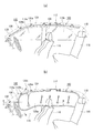
図1は、本発明の第1実施形態にかかるカーテンエアバッグを例示する図である。図1(a)は本実施形態にかかるカーテンエアバッグ(以下、「エアバッグ100」と記載する。)の非展開時、図1(b)はエアバッグ100の展開時をそれぞれ例示する。以下すべての実施形態を、図1のように車両102の右側面用のカーテンエアバッグとして説明するが、左側面用のカーテンエアバッグも同様の対称な構造を有する。
(First embodiment)
FIG. 1 is a diagram illustrating a curtain airbag according to the first embodiment of the present invention. FIG. 1A illustrates the curtain airbag according to this embodiment (hereinafter referred to as “
エアバッグ100は、図1(a)のように巻回された状態で、または折り畳まれた状態(図示省略)で、車両室内の側面部上方のルーフサイドレール104(図中、仮想線で例示する。)に取り付けられて収納される。通常、ルーフサイドレール104はルーフトリムで覆われ、車両室内からは視認不能である。ルーフサイドレール104には、ルーフ(屋根)を支える複数のピラーが接続している。これらは車両102の前方から、フロントピラー106、センタピラー108、リアピラー110と呼ばれる。
The
エアバッグ100は、例えば、その表面を構成する基布を表裏で縫製したり、OPW(One-Piece Woven)を用いて紡織したりすることにより袋状に形成される。
The
エアバッグ100には、ガス発生装置であるインフレータ112が備えられている。車両102に側面衝突時やロールオーバ(横転)等が発生すると、まず車両102に備えられたセンサ(図示省略)による衝撃の感知に起因して、インフレータ112へ発火信号が発信される。すると、インフレータ112の火薬が燃焼し、発生したガスがエアバッグ100へ供給される。
The
エアバッグ100は、インフレータ112からのガスを受給すると、図1(b)に例示するように、車室の側面部(サイドウィンドウ114a等)に沿うように下方へ膨張展開し、乗員の保護を行う。かかるエアバッグ100によれば、前部座席116および後部座席118の乗員を同時に保護可能である。
When the
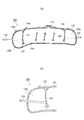
図2は、図1の展開状態のカーテンエアバッグを例示する図である。図2(a)は、エアバッグ100の車室側を一部透過した状態で例示していて、図2(b)は図2(a)のエアバッグ100の車両前方側付近を車外側から見て例示している。
FIG. 2 is a diagram illustrating the curtain airbag in the deployed state of FIG. FIG. 2A illustrates a state in which a part of the passenger compartment side of the
図2(a)に例示するように、エアバッグ100は車両102の衝突時や横転時に膨張する膨張領域120と、膨張せずに膨張領域120を区画する非膨張領域122(図中ハッチングで示す)と、を備えている。膨張領域120は非膨張領域122によって複数のチャンバに区画されている。チャンバは、衝突時等の非常事態時において乗員と直接接触する部分である。各チャンバによって、乗員は、車両側面部への激突や、車外への飛び出し等から保護される。
As illustrated in FIG. 2A, the
複数のチャンバのうち、エアバッグ100の車両前後方向の中央付近のやや前方にはメインチャンバ120aが設置されている。メインチャンバ120aは、図1(b)に例示するように前部座席116の略真横において膨張展開する。メインチャンバ120aは前部座席116の乗員に対して最も近い位置に膨張展開するため、通常の側面衝突によって衝撃を受けた乗員は大抵メインチャンバ120aによって保護される。
Of the plurality of chambers, a
本実施形態における端部チャンバとして、エアバッグ100の車両前後方向の前側にはフロントチャンバ120bが設置されている。フロントチャンバ120bは、図1(b)に例示するように前部座席空間の前側において膨張展開する。フロントチャンバ120bは、特にロールオーバ時において着座姿勢を大きく崩した前部座席116の乗員を保護する。フロントチャンバ120bの下縁は後方のメインチャンバ120a等の下縁よりも下方に突出していて、サイドウィンドウ114aの下方のドア部115に重畳する。これにより、サイドウィンドウ114aが破損して開口しても、フロントチャンバ120bの下縁側がドア部115に干渉するため、開口からのフロントチャンバ120bの車外への露出が防止できる。
As an end chamber in the present embodiment, a
図2(a)に例示するように、フロントチャンバ120bは、メインチャンバ120aとガス流入口134によって繋がっている。ガス流入口134には、ガスがメインチャンバ120aからフロントチャンバ120bに向かって通過する。非膨張領域122は、ガス流入口134の上方からエアバッグ100の上縁にわたるシーム部132を含んでいる。このシーム部132によって、フロントチャンバ120bはメインチャンバ120aから区分されている。
As illustrated in FIG. 2A, the
上記のフロントチャンバ120bは、メインチャンバ120aからのガスの受給がガス流入口134からに限られている。そのため、フロントチャンバ120bはメインチャンバ120aよりも遅れて膨張展開を開始する。換言すると、メインチャンバ120aはフロントチャンバ120bに優先して膨張展開を開始する。このメインチャンバ120aは側突発生時においてフロントチャンバ120bよりも乗員の接触可能性が高いため、これにより、エアバッグ100の乗員保護性能を向上させることが可能である。
In the
エアバッグ100の上縁には、取付部材として複数のタブ(タブ126a、126b)が設けられている。タブはエアバッグ100を車両102に取り付ける際に用いる帯状の部材である。タブ(タブ126b)には、車両102への締結用のボルトを通すボルト穴128が設けられている。
On the upper edge of the
本実施形態におけるストラップとして、エアバッグ100の前側には、フロントストラップ130が設けられている。フロントストラップ130は、膨張展開したエアバッグ100の姿勢を車両側面部に沿わせるように保持する紐状の部材である。図1(b)に例示するように、フロントストラップ130はフロントチャンバ120bの末端よりもさらに端部方向に離れた位置、すなわちフロントチャンバ120bの前方に位置するフロントピラー106に連結される。このフロントピラー106は、サイドウィンドウ114aよりも車内側に突出する部位である(図4(a)参照)。
As a strap in the present embodiment, a
フロントストラップ130は、膨張展開後のエアバッグ100によって、略直線状になる長さを有している。つまり、略直線状になるほどのテンションが膨張展開後のエアバッグ100から加わるよう、フロントストラップ130の長さは所定の長さ以下に決定されている。これにより、エアバッグ100の展開挙動は規制され、その姿勢が車両側面部に沿うように保持される。なお、フロントストラップ130は、膨張展開前から直線状になっていてもよい。
The
フロントストラップ130は、エアバッグ100の車外側であってフロントチャンバ120bの末端よりも中央側の領域、すなわち前端よりも後方の領域に縫合される。図2(b)に例示するように、本実施形態においてフロントストラップ130はシーム部132に取り付けられている。言い換えれば、フロントストラップ130は、フロントチャンバ120bの車外側の面を、フロントチャンバ120bの前端から後端であるシーム部132まで、前後方向に完全に横断している。シーム部132では基布が表裏一体となっているため、フロントストラップ130の取付強度を十分に確保できる。
The
図3は、図1(b)の概略的なA−A断面図である。ここで、エアバッグ100の膨張展開後において、フロントストラップ130はサイドウィンドウ114aよりも車内側へ突出するフロントピラー106と、エアバッグ100上のシーム部132との間で緊張し、略直線状の姿勢になる(図4(a)参照)。すると、図3に例示するようにフロントチャンバ120bのうちの少なくともフロントストラップ130と重畳する領域120dは、車外側への展開が防がれてサイドウィンドウ114aから離れる。領域120d以外のほとんどの領域についても、フロントチャンバ120bは、フロントストラップ130によってサイドウィンドウ114aから離れる。これにより、前部座席空間の前側においてフロントチャンバ120bと乗員との距離が近くなり、衝撃発生時において乗員は迅速にフロントチャンバ120bに接触可能となる。
FIG. 3 is a schematic AA sectional view of FIG. Here, after the
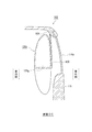
図4は、本実施形態にかかるカーテンエアバッグと従来のカーテンエアバッグとを比較する図である。図4(a)は本実施形態にかかるエアバッグ100を例示する図であって、図1(b)のB−B断面に対応している。図4(b)は従来のカーテンエアバッグ(以下、「エアバッグ10」と記載する。)であって、図4(a)のエアバッグ100に対応した断面を例示している。
FIG. 4 is a diagram comparing the curtain airbag according to the present embodiment and a conventional curtain airbag. FIG. 4A is a diagram illustrating the
図4(b)に例示するように、従来のエアバッグ10では、フロントストラップ12がフロントチャンバ14の前端に取り付けられていた。膨張展開後において、フロントストラップ12にはフロントチャンバ14によって車両後方へ向かって張力(テンション)が加えられ、緊張する。その際、フロントストラップ12と、フロントチャンバ14およびメインチャンバ16は車両側面部(サイドウィンドウ114a等)に沿って略一列に並ぶ姿勢となっていた。
As illustrated in FIG. 4B, in the
一方、図4(a)に例示するように、本実施形態にかかるエアバッグ100では、フロントストラップ130がフロントチャンバ120bの後方のシーム部132に取り付けられている。エアバッグ100の展開時の挙動は、その寸法やルーフサイドレール104への取付位置によって異なるが、エアバッグ100が巻回されていた状態から膨張展開するとき、シーム部132が当初の位置から後方に移動すると仮定する。その場合、このフロントストラップ130の長さは、フロントピラー106上の取付位置から、エアバッグ100の膨張展開によってシーム部132が移動しようとする位置までの長さよりも短く設定されている。すなわち、フロントストラップ130の長さは、シーム部132が目的の位置まで移動するのを阻むほどに短い。したがって、シーム部132は、略直線状になったフロントストラップ130によって止められ、移動しようとする位置まで実際には移動できない。一方、膨張展開後にはフロントストラップ130は、シーム部132によって車両後方へ引っ張られるように略直線状に緊張する。
On the other hand, as illustrated in FIG. 4A, in the
ここで、フロントストラップ130の前端が取り付けられているフロントピラー106は、サイドウィンドウ114aよりも車内側に突出(突出量≒幅W1)する部位である。そして、フロントストラップ130に車両後方へテンションが加えられることで、フロントチャンバ120bのフロントストラップ130と重畳する領域は、サイドウィンドウ114aから車内側へ離れる。したがって、従来のエアバッグ10のフロントチャンバ14と比較して、前部座席116の乗員との距離は近くなり、乗員を迅速に受け止めることが可能となる。
Here, the
上記のように、本実施形態ではフロントストラップ130をシーム部132に取り付けることにより、フロントチャンバ120bまたはフロントチャンバ120bの少なくとも一部(重畳する領域)の姿勢を変更させている。ここでシーム部132は膨張しない部分であって、図2(a)に示すようにエアバッグ100の上縁から下方のガス流入口134にわたって設置されている。したがって、フロントストラップ130に干渉したフロントチャンバ120bは、膨張展開時にシーム部132をあたかも回転軸のようにして車内側へ回動することが可能となっている。この回動により、フロントチャンバ120bを車内側へ容易に位置させることが可能である。
As described above, in this embodiment, by attaching the
再び図4を参照する。図4(b)に例示する従来のエアバッグ10のフロントチャンバ14では、図中に例示している車両前後方向の横断面が、車両前後方向に長軸aを有する略楕円となっている。そして、フロントチャンバ14は、乗員(図示省略)が略楕円の短軸bの略軸方向に接触する(乗員が部分120fに接触する)姿勢となっている。しかし図4(a)に例示するエアバッグ100では、シーム部132にフロントストラップ130を取り付けることで、フロントチャンバ120bのフロントストラップ130に重畳する部分は、長軸aの前端が車内側の斜め前方を向く姿勢となる。これにより乗員は、フロントチャンバ120bに対し、その短軸bの軸方向よりも厚み(≒幅W1)の有る部分120eへ接触可能となる。したがって、上記構成であれば、乗員からの荷重をより確実に吸収することが可能となっている。
Refer to FIG. 4 again. In the
さらに図4を参照して、サイドウィンドウ114aを基準としたフロントチャンバ14、120bのそれぞれの車内側への突出量を比較する。図4(b)のエアバッグ10では、サイドウィンドウ114aの厚みを無視すると、サイドウィンドウ114aから車内側へのフロントチャンバ14の突出量D1は、ほぼフロントチャンバ14の短軸bの軸方向の厚み(長さ)である。一方、図4(a)のエアバッグ100のフロントチャンバは、フロントピラー106に締結されたフロントストラップ130よりも車内側へ位置している。そのため、フロントチャンバ120bのサイドウィンドウ114aからの車内側への突出量D2は、フロントチャンバ120bの幅W1(幅W1は短軸bよりも厚い(長い))と、フロントピラー106の幅W2とを加えた量(W1+W2)となる。このように、本実施形態にかかるエアバッグ100では、従来のエアバッグ10と比較して、フロントチャンバ120bが車両側へ大きく突出(移動)している。
Further, referring to FIG. 4, the amounts of protrusion of the
上記説明したように、エアバッグ100は、フロントチャンバ120bを前部座席116の乗員に近い位置に配置させることで、衝撃を受けた際における乗員の着座位置からの移動量を減少させることができる。したがって、エアバッグ100であれば、ロールオーバの発生時において、前部座席116の乗員に対する車外放出防止性能の向上を図ることが可能である。
As described above, the
なお、図示しないものの、フロントストラップ130は、メインチャンバ120aまで延長してエアバッグ100に縫合してもよい。その場合、フロントチャンバ120bだけでなく、メインチャンバ120aの前部も、フロントストラップ130と重畳する領域において、車内側に位置することとなる。この場合、本実施形態と比較しても、膨張展開時に車内側に位置するエアバッグ100の領域が広くなる利点がある。一方、フロントストラップ130にかかる荷重が増大するため、本実施形態と比較すると、フロントチャンバ120bが車両側へ突出(移動)する量は減少する。
Although not shown, the
(第2実施形態)
図5は、本発明の第2実施形態にかかるカーテンエアバッグを例示する図である。図5は図2(b)に対応していて、第2実施形態にかかるカーテンエアバッグ(以下、「エアバッグ200」と記載する。)の車両前側付近を車外側から見て例示している。図5に例示するエアバッグ200は、フロントストラップの取付位置において第1実施形態のエアバッグ100と異なる。
(Second Embodiment)
FIG. 5 is a diagram illustrating a curtain airbag according to the second embodiment of the present invention. FIG. 5 corresponds to FIG. 2B, and illustrates the vicinity of the front side of the curtain airbag (hereinafter referred to as “
本実施形態におけるストラップとして、エアバッグ200が備えるフロントストラップ230は、フロントチャンバ120bの車外側の外表面に取り付けられている。この構成によっても、エアバッグ200の膨張展開後において、フロントチャンバ120bのうちの少なくともフロントストラップ230と重畳する領域はサイドウィンドウ114aから車外側へ離れ、より車内側に膨張展開する。
As a strap in the present embodiment, a
図6は、図5のカーテンエアバッグの車両内における膨張展開後を例示する図である。なお、図6は図4(a)に対応している。図6に例示するように、フロントストラップ230を備えることによっても、フロントチャンバ120bのサイドウィンドウ114aからの車内側への突出量D3は、フロントチャンバ120bの幅W3(幅W3は短軸bよりも厚い(長い))と、フロントピラー106の幅W2とを加えた量となる。したがって、フロントチャンバ120bを車内側に位置させて乗員を迅速に受け止め、乗員の着座位置からの移動量を減少させることが可能である。またこの構成によっても、フロントチャンバ120bのフロントストラップ230に重畳する部分は、長軸の前端が車内側の斜め前方を向く姿勢となる。これにより、乗員はフロントチャンバ120bに対してその短軸方向よりも厚みの有る部分へ接触可能となる。したがって、乗員からの荷重をより確実に吸収することが可能となっている。
FIG. 6 is a diagram illustrating the curtain airbag of FIG. 5 after being inflated and deployed in the vehicle. FIG. 6 corresponds to FIG. As illustrated in FIG. 6, by providing the
(各実施形態の第1の変形例)
図7は、各実施形態にかかるエアバッグの第1の変形例を例示する図である。以下では、各実施形態を代表して、第1実施形態にかかるエアバッグ100を参照して各実施形態の第1の変形例について説明する。なお、この図7は図2に対応している。
(First modification of each embodiment)
FIG. 7 is a diagram illustrating a first modification of the airbag according to each embodiment. Below, the 1st modification of each embodiment is demonstrated on behalf of each embodiment with reference to the
図7(a)に例示するように、エアバッグ300には、複数のチャンバのうちの1つとして、かつフロントチャンバ120bとは異なる端部チャンバとして、エアバッグ300の車両前後方向の後側にリアチャンバ120cが設置されている。そして、エアバッグ300の後側にはフロントストラップ130とは異なるストラップとして、リアストラップ330が設けられている。リアストラップ330は、フロントストラップ130と同様に、膨張展開したエアバッグ300の姿勢を車両側面部に沿わせるように保持する紐状の部材である。リアストラップ330は、エアバッグ300よりも後方のリアピラー110(図1(a)参照)に連結される。リアピラー110は、サイドウィンドウ114bよりも車内側に突出する部位である(図8参照)。
As illustrated in FIG. 7A, the
リアストラップ330は、エアバッグ300の車外側であってリアチャンバ120cの後端よりも前方の領域に縫合される。図7(b)に例示するように、当該エアバッグ300においてリアストラップ330は、リアチャンバ120cを前方の膨張領域120から区分するシーム部332に縫合されている。
The
図8は、図7のカーテンエアバッグの車両内における膨張展開後を例示する図である。なお、図8は図4(a)に対応している。図8に例示するように、エアバッグ300の膨張展開後において、リアストラップ330はエアバッグ300からのテンションが加わり、略直線状となる。すると、リアチャンバ120cのうちの少なくともリアストラップ330と重畳する領域はサイドウィンドウ114bよりも車外側へ離れ、より車内側に膨張展開することとなる。
FIG. 8 is a view illustrating the curtain airbag of FIG. 7 after being inflated and deployed in the vehicle. FIG. 8 corresponds to FIG. As illustrated in FIG. 8, after the
上記構成においても、リアストラップ330がフロントストラップ130と同様に作用することにより、後部座席空間の後側においてリアチャンバ120cと乗員との距離が近くなり、乗員は迅速にリアチャンバ120cに接触する。特に、リアチャンバ120cを乗員に近い位置に配置させることで、衝撃を受けた際における乗員の着座位置からの移動量を減少させることができる。したがって、ロールオーバの発生時において、後部座席118の乗員に対する車外放出防止性能の向上を図ることが可能である。
Also in the above configuration, the
(各実施形態の第2の変形例)
図9は、各実施形態にかかるエアバッグの第2の変形例を例示する図である。以下では、各実施形態を代表して、第1実施形態にかかるエアバッグ100を用いて第2の変形例について説明する。図9は図1に対応している。
(Second modification of each embodiment)
FIG. 9 is a diagram illustrating a second modification of the airbag according to each embodiment. Below, the 2nd modification is demonstrated using the
図9(b)に例示するように、エアバッグ400は幅広な形状の幅広ストラップ430を備えている。本変形例では、幅広ストラップ430は、フロントピラー106から略水平に延びてフロントチャンバ120bのほぼ中央を横断する第1の辺と、そこから略垂直上方に延びてルーフサイドレール104(あるいはフロントピラー106)に到達する第2の辺と、第1・第2の辺を結ぶ第3の辺とを含む。したがって幅広ストラップ430は、第3の辺を斜辺とする直角三角形に近い形状をしている。幅広ストラップ430は、縁の一点によってフロントピラー106に取り付けられ、第3の辺が位置するフロントピラー106からサイドウィンドウ114aの下部にかけて広範囲に広がり、フロントチャンバ120bのほぼ上半分という広い範囲を、サイドウィンドウ114aから離すことが可能となっている。
As illustrated in FIG. 9B, the
図10は、図9(b)の展開状態のカーテンエアバッグを例示する図である。図10(a)(b)はそれぞれ、図2(a)(b)と同様の方向からエアバッグ400を見た図である。図10(a)に例示するように、幅広ストラップ430の形状は略直角三角形となっていて、その斜辺(縁の一点から斜め上方に延びる縁)にはタブ432が設けられている。タブ432にはボルトを通すボルト穴434が設けられて、フロントピラー106またはルーフサイドレール104に取付可能となっている。
FIG. 10 is a diagram illustrating the curtain airbag in the deployed state of FIG. 9B. FIGS. 10A and 10B are views of the
図10(b)に例示するように、幅広ストラップ430は、縁の一点よりも車両の車両前後方向の中央側の領域、例えば後方側(図中、左側)の辺近傍においてシーム部132に縫合されている。幅広ストラップ430には、複数の肉抜穴436が設けられている。複数の肉抜穴436は、幅広ストラップ430上に千鳥状に形成されている。これにより、図9(a)に例示するような収納時の巻回状態において、巻回によって基布同士が重なる面積が減少する。したがって、広い面積を有する幅広ストラップ430ごとエアバッグ400を巻回しても、細くコンパクトな状態に巻回することが可能となっている。
As illustrated in FIG. 10B, the
図4(a)のフロントストラップ130と同様に、幅広ストラップ430はエアバッグ400の膨張展開後において、サイドウィンドウ114aよりも車内側へ突出するフロントピラー106と、エアバッグ100上のシーム部132との間で緊張し、車両前後方向に略平面状の姿勢になる。
Similar to the
図11は、図9(b)の概略的なC−C断面図である。図11に例示するように、フロントチャンバ120bのうちのフロントストラップ130と重畳する領域120gは、車外側への展開が防がれてサイドウィンドウ114aから離れる。特に三角巾状の幅広ストラップ430は、フロントチャンバ120gの上部側の大部分である領域120gに重畳し、サイドウィンドウ114aから離すことが可能である。
FIG. 11 is a schematic CC cross-sectional view of FIG. As illustrated in FIG. 11, the
しかも、フロントチャンバ120bにはタブ126b(図2(a)参照)は設けられていず、フロントビラー106に取り付けられていない。したがってフロントチャンバ120bは動作の自由度が高く、上下方向にわたって設置されているシーム部132をあたかも回転軸のようにして車内側へ回動しやすく、サイドウィンドウ114aから離すことが容易に可能である。
Moreover, the
フロントチャンバ120bがフロントビラー106に取り付けられていない一方、図9(b)に例示するように、幅広ストラップ430はその前端部分だけでなく、前端よりも後方のタブ432によってもフロントビラー106に取り付けられている。これにより、図11に例示する車内側から乗員がフロントチャンバ120bに接触しても、端部チャンバの乗員からの荷重の受け止めが不安定になることはなく、フロントチャンバ120bの領域120gをその車外側から確実に支え、乗員からの荷重を受け止めることが可能となっている。これらのように、幅広ストラップ430によってもフロントチャンバ120bと乗員との距離を近くし、ロールオーバの発生時の乗員に対する車外放出防止性能の向上を図ることが可能である。なお、図7に例示するリアストラップ330もまた、幅広ストラップ430と同様に幅広の形状とすることが可能である。
While the
以上、添付図面を参照しながら本発明の好適な実施形態について説明したが、以上に述べた実施形態は、本発明の好ましい例であって、これ以外の実施態様も、各種の方法で実施または遂行できる。特に本願明細書中に限定される主旨の記載がない限り、この発明は、添付図面に示した詳細な部品の形状、大きさ、および構成配置等に制約されるものではない。また、本願明細書の中に用いられた表現および用語は、説明を目的としたもので、特に限定される主旨の記載がない限り、それに限定されるものではない。 The preferred embodiments of the present invention have been described above with reference to the accompanying drawings. However, the embodiments described above are preferred examples of the present invention, and other embodiments can be implemented or performed in various ways. Can be carried out. The invention is not limited to the detailed shape, size, configuration, and the like of the components shown in the accompanying drawings unless otherwise specified in the present specification. In addition, expressions and terms used in the present specification are for the purpose of explanation, and are not limited thereto unless otherwise specified.
したがって、当業者であれば、特許請求の範囲に記載された範疇内において、各種の変更例または修正例に想到し得ることは明らかであり、それらについても当然に本発明の技術的範囲に属するものと了解される。 Therefore, it is obvious for those skilled in the art that various changes and modifications can be conceived within the scope of the claims, and these naturally belong to the technical scope of the present invention. It is understood.
また、上記実施形態においては本発明にかかるカーテンエアバッグを自動車に適用した例を説明したが、自動車以外にも航空機や船舶などに適用することも可能であり、同様の作用効果を得ることができる。 Moreover, in the said embodiment, although the example which applied the curtain airbag concerning this invention to the motor vehicle was demonstrated, it is also possible to apply to an aircraft, a ship, etc. besides a motor vehicle, and can obtain the same effect. it can.
本発明は、車両の側面衝突時やロールオーバ(横転)時に、乗員保護を目的として車両室内の側面部に沿って膨張展開するカーテンエアバッグに利用することができる。 INDUSTRIAL APPLICABILITY The present invention can be used for a curtain airbag that inflates and deploys along a side surface in a vehicle compartment for the purpose of protecting an occupant during a vehicle side collision or rollover (rollover).
a …長軸、b …短軸、D1、D2、D3 …突出量、W1、W2、W3 …幅、100、200、300、10 …エアバッグ、102 …車両、104 …ルーフサイドレール、106 …フロントピラー、108 …センターピラー、110 …リアピラー、112 …インフレータ、114 …サイドウィンドウ、115 …ドア部、116 …前部座席、118 …後部座席、120 …膨張領域、120a、16 …メインチャンバ、120b、14 …フロントチャンバ、120c …リアチャンバ、122 …非膨張領域、120d …領域、120e、120f …部分、126 …タブ、128 …ボルト穴、130、230、12 …フロントストラップ、132、332 …シーム部、134 …ガス流入口、330 …リアストラップ、400 …エアバッグ、430 …幅広ストラップ、432 …タブ、434 …ボルト穴、436 …肉抜穴 a ... long axis, b ... short axis, D1, D2, D3 ... protrusion amount, W1, W2, W3 ... width, 100, 200, 300, 10 ... airbag, 102 ... vehicle, 104 ... roof side rail, 106 ... Front pillar, 108 ... Center pillar, 110 ... Rear pillar, 112 ... Inflator, 114 ... Side window, 115 ... Door part, 116 ... Front seat, 118 ... Rear seat, 120 ... Expansion area, 120a, 16 ... Main chamber, 120b , 14 ... Front chamber, 120c ... Rear chamber, 122 ... Non-inflatable area, 120d ... Area, 120e, 120f ... Part, 126 ... Tab, 128 ... Bolt hole, 130, 230, 12 ... Front strap, 132, 332 ... Seam Part, 134 ... gas inlet, 330 ... rear Trap, 400 ... Airbag, 430 ... Wide strap, 432 ... Tab, 434 ... Bolt hole, 436 ... Thickening hole
Claims (7)
当該カーテンエアバッグの車両前後方向の端部に設置され、膨張展開用ガスを受けて膨張する端部チャンバと、
前記端部チャンバの車外側であって該端部チャンバの末端よりも中央側の領域と、該端部チャンバの末端よりもさらに端部方向に離れた位置においてサイドウィンドウよりも車内側に突出するピラーとを結ぶストラップと、
前記端部チャンバ以外の領域の上縁に車両前後方向に沿って設けられ、該端部チャンバ以外の領域を前記車両側室の側面部上方に取り付ける複数のタブとを備え、
前記ストラップは、膨張展開後の当該カーテンエアバッグによって前記側面部に沿って緊張し平面状に広がる幅広ストラップを含み、
前記幅広ストラップは、縁の一点および該縁の一点から斜め上方に延びる縁において前記ピラーに取り付けられ、これらの点よりも前記車両の車両前後方向の中央側の領域において当該カーテンエアバッグに取り付けられていることを特徴とするカーテンエアバッグ。 A curtain airbag that is housed above a side surface in a vehicle compartment and inflates and deploys along the side surface,
An end chamber that is installed at an end of the curtain airbag in the vehicle front-rear direction and receives and inflates and expands;
A central side region than ends of the end chamber a vehicle outside of said end chamber, protrudes inside the vehicle than the side window at a position further apart endwise than ends of said end chambers A strap that connects the pillar,
A plurality of tabs provided on the upper edge of the region other than the end chamber along the vehicle front-rear direction, and attaching the region other than the end chamber above the side surface of the vehicle side chamber ;
The strap includes a wide strap that is tensioned along the side surface portion and spreads in a planar shape by the curtain airbag after being inflated and deployed,
The wide strap is attached to the pillar at one point of the edge and an edge extending obliquely upward from the one point of the edge, and is attached to the curtain airbag in a central region in the vehicle longitudinal direction of the vehicle from these points. Tei curtain air bag which is characterized in Rukoto.
前記非膨張領域は、当該カーテンエアバッグの上縁から下方の前記ガス流入口にわたって設置されていることを特徴とする請求項4に記載のカーテンエアバッグ。 The end chamber has a gas inlet at the lower part for receiving the gas for expansion and deployment from the expansion region on the center side,
5. The curtain airbag according to claim 4 , wherein the non-inflatable region is installed from an upper edge of the curtain airbag to a lower gas inlet.
Priority Applications (1)
| Application Number | Priority Date | Filing Date | Title |
|---|---|---|---|
| JP2010162345A JP5595154B2 (en) | 2010-07-16 | 2010-07-16 | Curtain airbag |
Applications Claiming Priority (1)
| Application Number | Priority Date | Filing Date | Title |
|---|---|---|---|
| JP2010162345A JP5595154B2 (en) | 2010-07-16 | 2010-07-16 | Curtain airbag |
Publications (3)
| Publication Number | Publication Date |
|---|---|
| JP2012020719A JP2012020719A (en) | 2012-02-02 |
| JP2012020719A5 JP2012020719A5 (en) | 2013-07-04 |
| JP5595154B2 true JP5595154B2 (en) | 2014-09-24 |
Family
ID=45775338
Family Applications (1)
| Application Number | Title | Priority Date | Filing Date |
|---|---|---|---|
| JP2010162345A Active JP5595154B2 (en) | 2010-07-16 | 2010-07-16 | Curtain airbag |
Country Status (1)
| Country | Link |
|---|---|
| JP (1) | JP5595154B2 (en) |
Families Citing this family (21)
| Publication number | Priority date | Publication date | Assignee | Title |
|---|---|---|---|---|
| JP2012218618A (en) * | 2011-04-11 | 2012-11-12 | Toyota Motor Corp | Curtain air bag device |
| JP5387609B2 (en) * | 2011-04-11 | 2014-01-15 | トヨタ自動車株式会社 | Curtain airbag device |
| DE102011087449B4 (en) * | 2011-11-30 | 2019-04-25 | Autoliv Development Ab | Curtain airbag for a vehicle |
| JP5943767B2 (en) * | 2012-08-07 | 2016-07-05 | オートリブ ディベロップメント エービー | Curtain airbag for vehicle and method for manufacturing the same |
| JP6404542B2 (en) * | 2012-11-03 | 2018-10-10 | Joyson Safety Systems Japan株式会社 | Curtain airbag and curtain airbag device |
| JP5761220B2 (en) | 2013-02-05 | 2015-08-12 | トヨタ自動車株式会社 | Curtain airbag device |
| JP5783193B2 (en) | 2013-02-07 | 2015-09-24 | トヨタ自動車株式会社 | Curtain airbag device and occupant protection device |
| JP2014162313A (en) | 2013-02-22 | 2014-09-08 | Toyota Motor Corp | Curtain airbag device and occupant protective device |
| US9266494B2 (en) * | 2013-03-15 | 2016-02-23 | Autoliv Asp, Inc. | Fold over design for small overlap |
| JP6181443B2 (en) * | 2013-07-04 | 2017-08-16 | オートリブ ディベロップメント エービー | Curtain airbag device for vehicle |
| KR101718690B1 (en) * | 2014-02-12 | 2017-04-04 | 아우토리브 디벨롭먼트 아베 | Side curtain airbag for vehicle |
| JP6485279B2 (en) * | 2014-10-23 | 2019-03-20 | 豊田合成株式会社 | Head protection airbag device |
| US9505371B2 (en) | 2014-10-23 | 2016-11-29 | Toyoda Gosei Co., Ltd. | Head-protecting airbag device |
| JP6447122B2 (en) * | 2014-12-26 | 2019-01-09 | 豊田合成株式会社 | Head protection airbag device |
| JP2016124497A (en) * | 2015-01-07 | 2016-07-11 | 芦森工業株式会社 | Air bag |
| JP6036932B2 (en) * | 2015-06-29 | 2016-11-30 | トヨタ自動車株式会社 | Curtain airbag device and occupant protection device |
| JP6088037B2 (en) * | 2015-12-28 | 2017-03-01 | オートリブ ディベロップメント エービー | Mounting structure for curtain airbag for vehicle |
| KR101755952B1 (en) * | 2015-12-29 | 2017-07-10 | 현대자동차주식회사 | Curtain airbag for vehicle |
| KR101846710B1 (en) | 2016-09-21 | 2018-04-09 | 현대자동차주식회사 | Curtain airbag for vehicle |
| KR101878073B1 (en) * | 2016-11-04 | 2018-07-16 | 현대자동차주식회사 | Curtain air bag of vehicle |
| US10661744B2 (en) | 2017-06-30 | 2020-05-26 | Toyoda Gosei Co., Ltd. | Head protective airbag apparatus |
Family Cites Families (8)
| Publication number | Priority date | Publication date | Assignee | Title |
|---|---|---|---|---|
| GB2394921A (en) * | 2002-11-07 | 2004-05-12 | Autoliv Dev | A vehicle curtain type air bag rolled up when not in use |
| JP4481575B2 (en) * | 2003-02-26 | 2010-06-16 | 日本プラスト株式会社 | Curtain airbag |
| JP4481248B2 (en) * | 2003-10-27 | 2010-06-16 | オートリブ ディベロップメント エービー | Side curtain airbag |
| JP4432699B2 (en) * | 2004-09-24 | 2010-03-17 | 日本プラスト株式会社 | Airbag device |
| JP4830666B2 (en) * | 2006-06-28 | 2011-12-07 | 豊田合成株式会社 | Head protection airbag device |
| JP5163309B2 (en) * | 2008-06-24 | 2013-03-13 | マツダ株式会社 | Vehicle interior structure |
| JP5029578B2 (en) * | 2008-11-14 | 2012-09-19 | 豊田合成株式会社 | Head protection airbag device |
| US8282124B2 (en) * | 2009-03-05 | 2012-10-09 | Tk Holdings Inc. | Side curtain airbag having a main chamber and an extension chamber |
-
2010
- 2010-07-16 JP JP2010162345A patent/JP5595154B2/en active Active
Also Published As
| Publication number | Publication date |
|---|---|
| JP2012020719A (en) | 2012-02-02 |
Similar Documents
| Publication | Publication Date | Title |
|---|---|---|
| JP5595154B2 (en) | Curtain airbag | |
| JP5639263B2 (en) | Curtain airbag device for vehicle | |
| EP3492323B1 (en) | Far-side airbag device of vehicle | |
| JP5411660B2 (en) | Curtain airbag device | |
| JP5606876B2 (en) | Curtain airbag | |
| US10723303B2 (en) | Vehicle curtain airbag device | |
| US11104292B2 (en) | Side airbag device | |
| JP5623355B2 (en) | Curtain airbag | |
| JP5588980B2 (en) | Curtain airbag | |
| US9409543B2 (en) | Variable trajectory side curtain airbags | |
| JPWO2014061323A1 (en) | Curtain airbag | |
| JP6185653B2 (en) | Curtain airbag device | |
| WO2013146076A1 (en) | Head protection air bag system | |
| JP6247251B2 (en) | Side airbag device | |
| JP5990156B2 (en) | Curtain airbag device | |
| JP2010083240A (en) | Air-bag and airbag device | |
| JP6379444B2 (en) | Airbag device | |
| JP2005271755A (en) | Head protecting airbag device | |
| JP5901909B2 (en) | Curtain airbag | |
| JP6009655B2 (en) | Airbag device | |
| JP5948296B2 (en) | Curtain airbag device | |
| JP5615791B2 (en) | Curtain airbag | |
| JP4851155B2 (en) | Occupant protection system | |
| JP2007216819A (en) | Curtain airbag | |
| JP5846583B2 (en) | Curtain airbag |
Legal Events
| Date | Code | Title | Description |
|---|---|---|---|
| A521 | Request for written amendment filed |
Free format text: JAPANESE INTERMEDIATE CODE: A523 Effective date: 20130520 |
|
| A621 | Written request for application examination |
Free format text: JAPANESE INTERMEDIATE CODE: A621 Effective date: 20130520 |
|
| A131 | Notification of reasons for refusal |
Free format text: JAPANESE INTERMEDIATE CODE: A131 Effective date: 20140318 |
|
| A977 | Report on retrieval |
Free format text: JAPANESE INTERMEDIATE CODE: A971007 Effective date: 20140320 |
|
| A521 | Request for written amendment filed |
Free format text: JAPANESE INTERMEDIATE CODE: A523 Effective date: 20140611 |
|
| TRDD | Decision of grant or rejection written | ||
| A01 | Written decision to grant a patent or to grant a registration (utility model) |
Free format text: JAPANESE INTERMEDIATE CODE: A01 Effective date: 20140729 |
|
| A61 | First payment of annual fees (during grant procedure) |
Free format text: JAPANESE INTERMEDIATE CODE: A61 Effective date: 20140805 |
|
| R150 | Certificate of patent or registration of utility model |
Ref document number: 5595154 Country of ref document: JP Free format text: JAPANESE INTERMEDIATE CODE: R150 |
|
| R250 | Receipt of annual fees |
Free format text: JAPANESE INTERMEDIATE CODE: R250 |
|
| R250 | Receipt of annual fees |
Free format text: JAPANESE INTERMEDIATE CODE: R250 |
|
| R250 | Receipt of annual fees |
Free format text: JAPANESE INTERMEDIATE CODE: R250 |
|
| R250 | Receipt of annual fees |
Free format text: JAPANESE INTERMEDIATE CODE: R250 |
|
| R250 | Receipt of annual fees |
Free format text: JAPANESE INTERMEDIATE CODE: R250 |
|
| R250 | Receipt of annual fees |
Free format text: JAPANESE INTERMEDIATE CODE: R250 |
|
| R250 | Receipt of annual fees |
Free format text: JAPANESE INTERMEDIATE CODE: R250 |