EP3867504B1 - Abgasreinigungssystem und verfahren zur abgasreinigung - Google Patents
Abgasreinigungssystem und verfahren zur abgasreinigung Download PDFInfo
- Publication number
- EP3867504B1 EP3867504B1 EP19774115.0A EP19774115A EP3867504B1 EP 3867504 B1 EP3867504 B1 EP 3867504B1 EP 19774115 A EP19774115 A EP 19774115A EP 3867504 B1 EP3867504 B1 EP 3867504B1
- Authority
- EP
- European Patent Office
- Prior art keywords
- scrubber
- exhaust gas
- fraction
- fluid
- scrubber fluid
- Prior art date
- Legal status (The legal status is an assumption and is not a legal conclusion. Google has not performed a legal analysis and makes no representation as to the accuracy of the status listed.)
- Active
Links
Images

Classifications
-
- F—MECHANICAL ENGINEERING; LIGHTING; HEATING; WEAPONS; BLASTING
- F01—MACHINES OR ENGINES IN GENERAL; ENGINE PLANTS IN GENERAL; STEAM ENGINES
- F01N—GAS-FLOW SILENCERS OR EXHAUST APPARATUS FOR MACHINES OR ENGINES IN GENERAL; GAS-FLOW SILENCERS OR EXHAUST APPARATUS FOR INTERNAL-COMBUSTION ENGINES
- F01N3/00—Exhaust or silencing apparatus having means for purifying, rendering innocuous, or otherwise treating exhaust
- F01N3/02—Exhaust or silencing apparatus having means for purifying, rendering innocuous, or otherwise treating exhaust for cooling, or for removing solid constituents of, exhaust
- F01N3/04—Exhaust or silencing apparatus having means for purifying, rendering innocuous, or otherwise treating exhaust for cooling, or for removing solid constituents of, exhaust using liquids
-
- B—PERFORMING OPERATIONS; TRANSPORTING
- B01—PHYSICAL OR CHEMICAL PROCESSES OR APPARATUS IN GENERAL
- B01D—SEPARATION
- B01D53/00—Separation of gases or vapours; Recovering vapours of volatile solvents from gases; Chemical or biological purification of waste gases, e.g. engine exhaust gases, smoke, fumes, flue gases, aerosols
- B01D53/14—Separation of gases or vapours; Recovering vapours of volatile solvents from gases; Chemical or biological purification of waste gases, e.g. engine exhaust gases, smoke, fumes, flue gases, aerosols by absorption
- B01D53/1425—Regeneration of liquid absorbents
-
- B—PERFORMING OPERATIONS; TRANSPORTING
- B01—PHYSICAL OR CHEMICAL PROCESSES OR APPARATUS IN GENERAL
- B01D—SEPARATION
- B01D21/00—Separation of suspended solid particles from liquids by sedimentation
- B01D21/26—Separation of sediment aided by centrifugal force or centripetal force
- B01D21/262—Separation of sediment aided by centrifugal force or centripetal force by using a centrifuge
-
- B—PERFORMING OPERATIONS; TRANSPORTING
- B01—PHYSICAL OR CHEMICAL PROCESSES OR APPARATUS IN GENERAL
- B01D—SEPARATION
- B01D53/00—Separation of gases or vapours; Recovering vapours of volatile solvents from gases; Chemical or biological purification of waste gases, e.g. engine exhaust gases, smoke, fumes, flue gases, aerosols
- B01D53/14—Separation of gases or vapours; Recovering vapours of volatile solvents from gases; Chemical or biological purification of waste gases, e.g. engine exhaust gases, smoke, fumes, flue gases, aerosols by absorption
- B01D53/1412—Controlling the absorption process
-
- B—PERFORMING OPERATIONS; TRANSPORTING
- B01—PHYSICAL OR CHEMICAL PROCESSES OR APPARATUS IN GENERAL
- B01D—SEPARATION
- B01D53/00—Separation of gases or vapours; Recovering vapours of volatile solvents from gases; Chemical or biological purification of waste gases, e.g. engine exhaust gases, smoke, fumes, flue gases, aerosols
- B01D53/14—Separation of gases or vapours; Recovering vapours of volatile solvents from gases; Chemical or biological purification of waste gases, e.g. engine exhaust gases, smoke, fumes, flue gases, aerosols by absorption
- B01D53/1493—Selection of liquid materials for use as absorbents
-
- C—CHEMISTRY; METALLURGY
- C02—TREATMENT OF WATER, WASTE WATER, SEWAGE, OR SLUDGE
- C02F—TREATMENT OF WATER, WASTE WATER, SEWAGE, OR SLUDGE
- C02F1/00—Treatment of water, waste water, or sewage
- C02F1/38—Treatment of water, waste water, or sewage by centrifugal separation
- C02F1/385—Treatment of water, waste water, or sewage by centrifugal separation by centrifuging suspensions
-
- C—CHEMISTRY; METALLURGY
- C02—TREATMENT OF WATER, WASTE WATER, SEWAGE, OR SLUDGE
- C02F—TREATMENT OF WATER, WASTE WATER, SEWAGE, OR SLUDGE
- C02F1/00—Treatment of water, waste water, or sewage
- C02F1/44—Treatment of water, waste water, or sewage by dialysis, osmosis or reverse osmosis
-
- F—MECHANICAL ENGINEERING; LIGHTING; HEATING; WEAPONS; BLASTING
- F01—MACHINES OR ENGINES IN GENERAL; ENGINE PLANTS IN GENERAL; STEAM ENGINES
- F01N—GAS-FLOW SILENCERS OR EXHAUST APPARATUS FOR MACHINES OR ENGINES IN GENERAL; GAS-FLOW SILENCERS OR EXHAUST APPARATUS FOR INTERNAL-COMBUSTION ENGINES
- F01N13/00—Exhaust or silencing apparatus characterised by constructional features
- F01N13/004—Exhaust or silencing apparatus characterised by constructional features specially adapted for marine propulsion, i.e. for receiving simultaneously engine exhaust gases and engine cooling water
-
- B—PERFORMING OPERATIONS; TRANSPORTING
- B01—PHYSICAL OR CHEMICAL PROCESSES OR APPARATUS IN GENERAL
- B01D—SEPARATION
- B01D2247/00—Details relating to the separation of dispersed particles from gases, air or vapours by liquid as separating agent
- B01D2247/04—Regenerating the washing fluid
-
- B—PERFORMING OPERATIONS; TRANSPORTING
- B01—PHYSICAL OR CHEMICAL PROCESSES OR APPARATUS IN GENERAL
- B01D—SEPARATION
- B01D2252/00—Absorbents, i.e. solvents and liquid materials for gas absorption
- B01D2252/10—Inorganic absorbents
- B01D2252/103—Water
-
- C—CHEMISTRY; METALLURGY
- C02—TREATMENT OF WATER, WASTE WATER, SEWAGE, OR SLUDGE
- C02F—TREATMENT OF WATER, WASTE WATER, SEWAGE, OR SLUDGE
- C02F2103/00—Nature of the water, waste water, sewage or sludge to be treated
- C02F2103/18—Nature of the water, waste water, sewage or sludge to be treated from the purification of gaseous effluents
-
- F—MECHANICAL ENGINEERING; LIGHTING; HEATING; WEAPONS; BLASTING
- F01—MACHINES OR ENGINES IN GENERAL; ENGINE PLANTS IN GENERAL; STEAM ENGINES
- F01N—GAS-FLOW SILENCERS OR EXHAUST APPARATUS FOR MACHINES OR ENGINES IN GENERAL; GAS-FLOW SILENCERS OR EXHAUST APPARATUS FOR INTERNAL-COMBUSTION ENGINES
- F01N2570/00—Exhaust treating apparatus eliminating, absorbing or adsorbing specific elements or compounds
- F01N2570/04—Sulfur or sulfur oxides
-
- F—MECHANICAL ENGINEERING; LIGHTING; HEATING; WEAPONS; BLASTING
- F01—MACHINES OR ENGINES IN GENERAL; ENGINE PLANTS IN GENERAL; STEAM ENGINES
- F01N—GAS-FLOW SILENCERS OR EXHAUST APPARATUS FOR MACHINES OR ENGINES IN GENERAL; GAS-FLOW SILENCERS OR EXHAUST APPARATUS FOR INTERNAL-COMBUSTION ENGINES
- F01N2590/00—Exhaust or silencing apparatus adapted to particular use, e.g. for military applications, airplanes, submarines
- F01N2590/02—Exhaust or silencing apparatus adapted to particular use, e.g. for military applications, airplanes, submarines for marine vessels or naval applications
-
- F—MECHANICAL ENGINEERING; LIGHTING; HEATING; WEAPONS; BLASTING
- F01—MACHINES OR ENGINES IN GENERAL; ENGINE PLANTS IN GENERAL; STEAM ENGINES
- F01N—GAS-FLOW SILENCERS OR EXHAUST APPARATUS FOR MACHINES OR ENGINES IN GENERAL; GAS-FLOW SILENCERS OR EXHAUST APPARATUS FOR INTERNAL-COMBUSTION ENGINES
- F01N2610/00—Adding substances to exhaust gases
- F01N2610/14—Arrangements for the supply of substances, e.g. conduits
- F01N2610/1406—Storage means for substances, e.g. tanks or reservoirs
-
- Y—GENERAL TAGGING OF NEW TECHNOLOGICAL DEVELOPMENTS; GENERAL TAGGING OF CROSS-SECTIONAL TECHNOLOGIES SPANNING OVER SEVERAL SECTIONS OF THE IPC; TECHNICAL SUBJECTS COVERED BY FORMER USPC CROSS-REFERENCE ART COLLECTIONS [XRACs] AND DIGESTS
- Y02—TECHNOLOGIES OR APPLICATIONS FOR MITIGATION OR ADAPTATION AGAINST CLIMATE CHANGE
- Y02T—CLIMATE CHANGE MITIGATION TECHNOLOGIES RELATED TO TRANSPORTATION
- Y02T10/00—Road transport of goods or passengers
- Y02T10/10—Internal combustion engine [ICE] based vehicles
- Y02T10/12—Improving ICE efficiencies
Definitions
- the invention relates to an exhaust gas cleaning system for cleaning exhaust gas onboard a ship, e.g. from a marine engine, burner or boiler.
- the invention also relates to a method for cleaning exhaust gas onboard a ship, e.g. from a marine engine, burner or boiler, by means of such an exhaust gas cleaning system.
- exhaust gas containing sulphur oxides SOx
- SOx sulphur oxides
- the exhaust gas typically also contains particulate matter, such as soot, oil and heavy metals, and nitrogen oxides (NOx).
- NOx nitrogen oxides
- the exhaust gas should be cleaned before it is released into the atmosphere.
- the exhaust gas could be passed through a scrubber to be washed with a scrubber fluid whereby pollutants in the exhaust gas are caught in the scrubber fluid.
- the scrubber could be a so-called open loop scrubber, which uses the natural alkalinity of seawater to wash out the sulphur oxides from the exhaust gas. Seawater is then fed from the sea through the scrubber for absorption of SOx and particulate matter from the exhaust gas before it is discharged directly back to the sea.
- the scrubber could be a so-called closed loop scrubber which uses circulating freshwater or seawater in combination with an alkaline agent like sodium hydroxide (NaOH) or sodium carbonate (Na 2 CO 3 ) to wash out sulphur oxides and particulate matter from the exhaust gas.
- an alkaline agent like sodium hydroxide (NaOH) or sodium carbonate (Na 2 CO 3 ) to wash out sulphur oxides and particulate matter from the exhaust gas.
- NaOH sodium hydroxide
- Na 2 CO 3 sodium carbonate
- the amounts of aqueous sulphite, sulphate salts and particulate matter in the circulating freshwater or seawater are gradually increasing.
- a small amount of it may occasionally or continuously be replaced by clean freshwater or seawater and either be stored on the ship or be discharged overboard after cleaning from particulate matter.
- WO 2011/104302 describes an exhaust gas cleaning equipment comprising a closed loop scrubber and a centrifugal separator for separating polluted scrubber fluid into a pollutant phase, which contains most of the particulate matter, and cleaned scrubber fluid.
- this exhaust gas cleaning equipment functions well, it may not be capable of producing cleaned scrubber fluid sufficiently free from particulate matter to be discharged overboard, especially if the flow of scrubber fluid is high. If the cleaned scrubber fluid cannot be discharged overboard, it must be stored on board the ship for later discharge.
- JP 2004 081933 discloses a wastewater treatment equipment for treating wastewater from a gas washing scrubber for washing a combustion exhaust gas.
- An object of the present invention is to provide an exhaust gas cleaning system for cleaning exhaust gas onboard a ship and a method for cleaning exhaust gas by means of such a system that at least partly solve the above mentioned problem.
- the basic concept of the invention is to use a centrifugal separator for removing most of the particulate matter, herein also referred to as PM, from the scrubber fluid and then a membrane filter for removing residues of particulate matter from the scrubber fluid to make it clean enough to be discharged overboard.
- the exhaust gas system and the method according to the invention are defined in the appended claims and discussed below.
- An exhaust gas cleaning system is arranged for cleaning exhaust gas onboard a ship. It comprises a first sub system which includes a scrubber unit and a centrifugal separator.
- the scrubber unit comprises a scrubber arranged to wash the exhaust gas with a scrubber fluid.
- the centrifugal separator is arranged in communication with the scrubber unit for receiving the scrubber fluid after washing and separate it into a first and a second fraction, which second fraction is more polluted, i.e. dirtier, than the first fraction.
- the scrubber comprises an exhaust gas inlet for receiving the exhaust gas and an exhaust gas outlet for outputting the washed exhaust gas.
- the exhaust gas cleaning system is characterized in that it further comprises a second sub system including a membrane filter.
- the membrane filter is arranged in communication with the centrifugal separator for receiving the first fraction output from the centrifugal separator and separating it into a third and a fourth fraction, which fourth fraction is more polluted, i.e. dirtier, than the third fraction.
- the exhaust gas cleaning system could be arranged for cleaning exhaust gas from a marine engine onboard a ship, a marine burner onboard a ship or a marine boiler onboard s ship.
- the centrifugal separator may receive all, nothing or some of the scrubber fluid from the scrubber unit, and this may vary over time.
- the membrane filter may receive all, nothing or some of the first fraction of the scrubber fluid from the centrifugal separator, and this may vary over time.
- the centrifugal separator may, for example, be a high speed separator, a decanter, or a combination thereof.
- the membrane filter may, for example, be polymeric or ceramic, or a combination thereof. Further, the membrane filter may be of cross flow type.
- the centrifugal separator may receive scrubber fluid from the scrubber unit, cleaning or the scrubber fluid from particulate matter absorbed from the exhaust gas may be enabled.
- the membrane filter may receive the first fraction of the scrubber fluid, i.e. the cleaned scrubber fluid, from the centrifugal separator, further cleaning of the scrubber fluid from particulate matter absorbed from the exhaust gas may be enabled.
- a scrubber fluid inlet of the scrubber may be arranged in communication with a scrubber fluid outlet of the scrubber. Thereby, recirculation of scrubber fluid, i.e. a closed loop scrubber, may be enabled.
- the scrubber unit may further comprise a circulation tank, wherein the circulation tank is in communication with the scrubber, e.g. with the scrubber fluid outlet thereof, for receiving the scrubber fluid from the scrubber after washing, the circulation tank is in communication with the scrubber, e.g. with the scrubber fluid inlet thereof, for feeding the scrubber fluid to the scrubber, and the circulation tank is in communication with the centrifugal separator for feeding the scrubber fluid to the centrifugal separator.
- the circulation tank is in communication with the scrubber, e.g. with the scrubber fluid outlet thereof, for receiving the scrubber fluid from the scrubber after washing
- the circulation tank is in communication with the scrubber, e.g. with the scrubber fluid inlet thereof, for feeding the scrubber fluid to the scrubber
- the circulation tank is in communication with the centrifugal separator for feeding the scrubber fluid to the centrifugal separator.
- the centrifugal separator may be in communication with the scrubber unit for feeding the first fraction of the scrubber fluid to the scrubber unit, e.g. the scrubber and/or the circulation tank, if such is present, thereof.
- the scrubber unit e.g. the scrubber and/or the circulation tank, if such is present, thereof.
- the centrifugal separator may feed all, nothing or some of the first fraction of the scrubber fluid to the scrubber unit, and this may vary over time.
- the first sub system may further comprise a switching module communicating with the centrifugal separator, the scrubber unit and the membrane filter.
- the switching module may be arranged to receive the first fraction of the scrubber fluid output from the centrifugal separator and feed the first fraction of the scrubber fluid to the membrane filter and/or the scrubber unit.
- the switching module may receive all, nothing or some of the first fraction of the scrubber fluid from the centrifugal separator, and this may vary over time. Further, the switching module may feed all, nothing or some of the first fraction of the scrubber fluid to the membrane filter and/or the scrubber unit, and this may vary over time.
- the membrane filter may be in communication with the scrubber unit for feeding the fourth fraction of the scrubber fluid to the scrubber unit, e.g. the scrubber and/or the circulation tank, if such is present, thereof.
- the membrane filter may feed all, nothing or some of the fourth fraction of the scrubber fluid to the scrubber unit, and this may vary over time.
- the second sub system may further comprise a water analysis unit arranged to determine a number ⁇ 1 of parameter values of the third fraction of the scrubber fluid.
- the parameter values can be used to decide on further handling of the third fraction of the scrubber fluid.
- the membrane filter may be in communication with the scrubber unit for feeding the third fraction of the scrubber fluid to the scrubber unit, i.e. the scrubber or the circulation tank, if such is present, thereof, if at least one of said parameter values exceeds or equals a respective limit value. Then, the third fraction of the scrubber fluid may be too dirty to be discharged from the exhaust gas system.
- the exhaust gas cleaning system may be arranged to discharge the third fraction of the scrubber fluid from the exhaust gas cleaning system if each of said parameter values is below said respective limit value.
- the third fraction of the scrubber fluid may be discharged overboard, or to a temporary storage tank for later discharge overboard.
- the first sub system may further comprise a chemical dosing unit arranged to supply a chemical substance to the scrubber fluid.
- the chemical dosing unit may be arranged to supply the chemical substance to the scrubber fluid downstream the scrubber unit and upstream, i.e. before it is received by, the centrifugal separator.
- the chemical substance may contain a flocculant and/or a coagulant. Thereby, the efficiency of the centrifugal separator may be optimized.
- the chemical substance may contain an alkaline agent for adjusting the pH of the scrubber fluid.
- the first sub system may further comprise a flocculation unit downstream the chemical dosing unit and upstream the centrifugal separator arranged to hold the scrubber fluid before it is received by the centrifugal separator to allow sufficient time for flocculation.
- a flocculation unit downstream the chemical dosing unit and upstream the centrifugal separator arranged to hold the scrubber fluid before it is received by the centrifugal separator to allow sufficient time for flocculation.
- a method according to the present invention is arranged for cleaning exhaust gas onboard a ship by means of an exhaust gas cleaning system.
- the method comprises washing the exhaust gas with a scrubber fluid in a scrubber comprised in a scrubber unit, and separating the scrubber fluid, after washing, in a centrifugal separator, into a first and a second fraction, which second fraction is more polluted than the first fraction.
- the scrubber unit and the centrifugal separator are comprised in a first sub system of the exhaust gas cleaning system.
- the method is characterized in further comprising passing the first fraction of the scrubber fluid through a membrane filter to separate it into a third and a fourth fraction, which fourth fraction is more polluted than the third fraction.
- the membrane filter is comprised in a second sub system of the exhaust gas cleaning system.
- the method could be arranged for cleaning exhaust gas from a marine engine onboard a ship, a marine burner onboard a ship or a marine boiler onboard a ship.
- the method may further comprise recirculating the scrubber fluid through the scrubber.
- the method may further comprise feeding the first fraction of the scrubber fluid to the scrubber unit from the centrifugal separator.
- the method may further comprise feeding the fourth fraction of the scrubber fluid to the scrubber unit.
- the method may further comprise determining a number ⁇ 1 of parameter values of the third fraction of the scrubber fluid.
- the method may further comprise feeding the third fraction of the scrubber fluid to the scrubber unit if at least one of said parameter values exceeds or equals a respective limit value.
- the method may further comprise discharging the third fraction of the scrubber fluid from the exhaust gas cleaning system if each of said parameter values is below said respective limit value.
- the method may further comprise supplying a chemical substance, containing e.g. a flocculant and/or a coagulant and/or a pH adjusting alkaline agent, to the scrubber fluid in the first sub system, e.g. downstream the scrubber unit and upstream the centrifugal separator. Further, the method may comprise holding the scrubber fluid in a flocculation unit after supply of the chemical substance to it and before it is fed to the centrifugal separator to enable sufficient time for flocculation.
- a chemical substance containing e.g. a flocculant and/or a coagulant and/or a pH adjusting alkaline agent
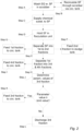
- Fig. 1 illustrates an exhaust gas cleaning system 1 comprising a first sub system 3 and a second sub system 5.
- the first sub system 3 comprises a flocculation unit 7, a centrifugal separator 9 in the form of a high speed separator, a sludge tank 10, a chemical dosing unit 11, a switching module 13 and a scrubber unit 15, which scrubber unit 15 contains a scrubber 17 and a circulation tank 19.
- the second sub system 5 comprises a membrane filter 21 of cross flow type with a pore size of 0,15 micro meter, a water analysis unit 23 and a switching module 25.
- the exhaust gas cleaning system is configured to clean exhaust gas EG from a marine diesel engine 27 on board a ship (not illustrated).
- the scrubber 17 comprises an exhaust gas inlet 29 for receiving the exhaust gas EG from the engine 27 and an exhaust gas outlet 31 for releasing washed exhaust gas EGW.
- Fig. 2 illustrates a method for cleaning the exhaust gas EG from the engine 27.
- a scrubber fluid SF (Step A) in the form of freshwater containing an alkaline agent like sodium hydroxide (NaOH).
- the scrubber works in a conventional way not further described herein.
- the scrubber fluid SF is fed from the circulation tank 19 to the scrubber 17 through a scrubber fluid inlet 33 thereof.
- the scrubber fluid SF absorbs pollutants from the exhaust gas EG to clean it whereupon the scrubber fluid SF is fed through a scrubber fluid outlet 35 back to the circulation tank 19. Therefore, the scrubber fluid inlet 33 communicates indirectly, i.e. via the circulation tank 19, with the scrubber fluid outlet 35 whereby the scrubber fluid SF is recirculated through the scrubber 17 (Step B).
- a chemical substance, containing a coagulant in the form of poly aluminum chloride and the alkaline agent for adjusting the scrubber fluid pH to 6,5, is supplied, by the chemical dosing unit 11, to the scrubber fluid SF pumped off from the circulation tank 19 (Step C) before it is received in the flocculation unit 7 communicating with the circulation tank 19.
- the coagulant-containing scrubber fluid SF is held and mixed to enable proper flocculation (Step D) before it is received by the centrifugal separator 9 communicating with the flocculation unit 7, and thus (indirectly) with the circulation tank 9.
- the centrifugal separator 9 separates the flocks-containing scrubber fluid SF into first and second fractions (Step E).
- the second fraction which is more polluted than the first fraction, is discharged to the sludge tank 10 (Step F). What happens to the cleaner first fraction depends on which mode the exhaust gas cleaning system 1 is in.
- the switching module 13 is set such that 100% of the first fraction is fed back to the scrubber unit 15, more particularly the circulation tank 19 thereof (Step G), which is in communication with the centrifugal separator 9, whereby the circulation tank 19 is replenished with cleaned scrubber fluid.
- the switching module 13 is set such that x%, 0 ⁇ x ⁇ 100, of the first fraction is fed back to the circulation tank 19 (Step G) to replenish the same (depending on the value of x), while (100-x)% of the first fraction is fed to the membrane filter 21, which is in communication with the centrifugal separator 9.
- x is adjustable and may be kept constant or varied during operation of the exhaust gas cleaning system 1. Whether the exhaust gas cleaning system 1 is in the first mode or the second mode depends, inter alia, on the amount of aqueous sulphite and sulphate salts in the scrubber fluid, and the amount of scrubber fluid in the first sub system 3.
- the membrane filter 21 separates the first fraction into third and fourth fractions (Step H).
- the fourth fraction which is more polluted than the third fraction, is fed back to the scrubber unit 15, more particularly the circulation tank 19 thereof (Step I), which is in communication with the membrane filter 21, whereby the circulation tank 19 is replenished with scrubber fluid.
- Step H the fourth fraction, which is more polluted than the third fraction, is fed back to the scrubber unit 15, more particularly the circulation tank 19 thereof (Step I), which is in communication with the membrane filter 21, whereby the circulation tank 19 is replenished with scrubber fluid. What happens to the cleaner third fraction depends on how polluted it is.
- a turbidity value, a pH value and a PAH (Polycyclic Aromatic Hydrocarbons) value of the third fraction is determined by the water analysis unit 23 (Step J) and communicated to the switching module 25.
- the switching module 25 is set such that, if one or more of the turbidity values, the pH value and the PAH value exceeds or equals a respective limit value, here 25 NTU, 6,5 and 2250 ppb, respectively, the third fraction is fed back to the scrubber unit 15, more particularly the circulation tank 19 thereof (Step K), which is in communication with the membrane filter 21, whereby the circulation tank 19 is replenished with cleaned scrubber fluid.
- the third fraction is discharged from the exhaust gas cleaning system 1 (Step L), overboard or to a temporary holding tank (not illustrated) for later discharge, for example if the ship is in an area where discharge overboard is prohibited.
- the scrubber fluid pumped off from the circulation tank 19 is cleaned first by means of the centrifugal separator 9.
- the centrifugal separator 9 efficiently removes most of the particulate matter and is capable of handling very high levels of PM without getting blocked.
- the centrifugal separator 9 is capable and suitable for keeping the scrubber fluid circulating in the first sub system 3 of the exhaust gas cleaning system 1 sufficiently free from PM.
- the centrifugal separator 9 may be uncapable of removing enough particulate matter to make the scrubber fluid clean enough to be discharged overboard.
- the cleaned, here first, fraction of the scrubber fluid is then cleaned further by means of the membrane filter 21.
- the membrane filter 21 efficiently removes nearly all of the remaining particulate matter. Since the scrubber fluid fed through the membrane filter 21 has been pre-cleaned by the centrifugal separator 9, the level of PM in the scrubber fluid is low enough not to clog the membrane filter 21. Thereby, a significantly higher flow through the membrane filter than normal is enabled.
- the components of the above described exhaust gas cleaning system are connected by suitable piping to allow them to communicate in the above specified way.
- the exhaust gas system described above may comprise additional components to make it work properly, such as pumps, valves, sensors, further water analysis units, control units etc.
- the exhaust gas system may comprise a pH meter or sensor between the scrubber and the circulation tank for measuring the pH of the scrubber fluid. This pH meter may communicate with the chemical dosing unit 11.
- Step A the steps of the method according to the invention have been named Step A, Step B, etc. just for identification purposes.
- the steps need not be performed in the specific order Step A, Step B, etc.
- one or more steps may be left out in alternative embodiments.
- the exhaust gas cleaning system could be operated with other coagulants than the above specified, with a flocculant, for example a polymer, instead of a coagulant, or with a mixture of coagulant and flocculant.
- a flocculant for example a polymer, instead of a coagulant, or with a mixture of coagulant and flocculant.
- the membrane filter may have another pore size than the above given, both larger and smaller.
- the water analysis unit 23 is arranged to determine a turbidity value, a pH value and a PAH value of the third fraction of the scrubber fluid and the handling of the third fraction is dependent on these values.
- the water analysis unit may be arranged to determine only one or two of these parameters, additional parameters and/or other parameters.
- the exhaust gas cleaning system need not comprise a circulation tank.
- the centrifugal separator 9 could be arranged to feed the first fraction to the scrubber 17 instead of to a circulation tank.
- the exhaust gas cleaning system could be of open loop type so as to not include recirculation or return of the scrubber fluid.
- the scrubber fluid need not comprise freshwater and an alkaline agent but could instead comprise seawater and an alkaline agent or a combination thereof.
Landscapes
- Engineering & Computer Science (AREA)
- Chemical & Material Sciences (AREA)
- Combustion & Propulsion (AREA)
- Mechanical Engineering (AREA)
- Chemical Kinetics & Catalysis (AREA)
- General Engineering & Computer Science (AREA)
- Analytical Chemistry (AREA)
- General Chemical & Material Sciences (AREA)
- Oil, Petroleum & Natural Gas (AREA)
- Ocean & Marine Engineering (AREA)
- Life Sciences & Earth Sciences (AREA)
- Hydrology & Water Resources (AREA)
- Environmental & Geological Engineering (AREA)
- Water Supply & Treatment (AREA)
- Organic Chemistry (AREA)
- Treating Waste Gases (AREA)
- Exhaust Gas After Treatment (AREA)
- Separation Using Semi-Permeable Membranes (AREA)
- Gas Separation By Absorption (AREA)
- Separating Particles In Gases By Inertia (AREA)
- Processes For Solid Components From Exhaust (AREA)
Claims (15)
- Abgasreinigungssystem (1) zum Reinigen von Abgas (EG) an Bord eines Schiffes, bei dem das Abgasreinigungssystem (1) ein erstes Untersystem (3) umfasst, das Folgendes einschließt:eine Scrubber-Einheit (15), die einen Scrubber (17) umfasst, der dafür angeordnet ist, das Abgas (EG) mit einem Scrubber-Fluid zu waschen undeinen Zentrifugalabscheider (9), der in Verbindung mit der Scrubber-Einheit (15) angeordnet ist, um das Scrubber-Fluid nach dem Waschen aufzunehmen und es in eine erste und eine zweite Fraktion zu trennen, von denen die zweite Fraktion stärker verunreinigt ist als die erste Fraktion,wobei der Scrubber (17) einen Abgaseinlass (29) zum Aufnehmen des Abgases (EG) und einen Abgasauslass (31) zum Ausgeben des gewaschenen Abgases (EGW) umfasst,wobei das Abgasreinigungssystem (1) dadurch gekennzeichnet ist, dass es ferner Folgendes umfasst:
ein zweites Untersystem (5), das einen Membranfilter (21) einschließt, der in Verbindung mit dem Zentrifugalabscheider (9) angeordnet ist, um die erste Fraktion, die aus dem Zentrifugalabscheider (9) ausgegeben wird, aufzunehmen und sie in eine dritte und eine vierte Fraktion zu trennen, von denen die vierte Fraktion stärker verunreinigt ist als die dritte Fraktion. - Abgasreinigungssystem (1) nach Anspruch 1, wobei ein Scrubber-Fluideinlass (33) des Scrubbers (17) in Verbindung mit einem Scrubber-Fluidauslass (35) des Scrubbers (17) angeordnet ist.
- Abgasreinigungssystem (1) nach Anspruch 2, wobei die Scrubber-Einheit (15) ferner einen Umwälzbehälter (19) umfasst, wobei der Umwälzbehälter (19) in Verbindung mit dem Scrubber (17) steht, um das Scrubber-Fluid aus dem Scrubber (17) nach dem Waschen aufzunehmen, der Umwälzbehälter (19) in Verbindung mit dem Scrubber (17) steht, um das Scrubber-Fluid dem Scrubber (17) zuzuführen, und der Umwälzbehälter (19) in Verbindung mit dem Zentrifugalabscheider (9) steht, um das Scrubber-Fluid dem Zentrifugalabscheider (9) zuzuführen.
- Abgasreinigungssystem (1) nach einem der vorhergehenden Ansprüche, wobei der Zentrifugalabscheider (9) in Verbindung mit der Scrubber-Einheit (15) steht, um die erste Fraktion des Scrubber-Fluids der Scrubber-Einheit (15) zuzuführen.
- Abgasreinigungssystem (1) nach einem der vorhergehenden Ansprüche, wobei der Membranfilter (21) in Verbindung mit der Scrubber-Einheit (15) steht, um die vierte Fraktion des Scrubber-Fluids der Scrubber-Einheit (15) zuzuführen.
- Abgasreinigungssystem (1) nach einem der vorhergehenden Ansprüche, wobei das zweite Untersystem (5) ferner eine Wasseranalyseeinheit (23) umfasst, die dafür angeordnet ist, eine Anzahl ≥ 1 von Parameterwerten der dritten Fraktion des Scrubber-Fluids zu bestimmen.
- Abgasreinigungssystem (1) nach Anspruch 6, wobei der Membranfilter (21) in Verbindung mit der Scrubber-Einheit (15) steht, um die dritte Fraktion des Scrubber-Fluids der Scrubber-Einheit (15) zuzuführen, falls mindestens einer der Parameterwerte einen jeweiligen Grenzwert überschreitet oder demselben gleichkommt.
- Abgasreinigungssystem (1) nach Anspruch 7, die dafür angeordnet ist, die dritte Fraktion des Scrubber-Fluids aus dem Abgasreinigungssystem (1) abzugeben, falls jeder der Parameterwerte unterhalb des jeweiligen Grenzwerts liegt.
- Verfahren zum Reinigen von Abgas an Bord eines Schiffes mittels eines Abgasreinigungssystems, Folgendes umfassend:Waschen des Abgases mit einem Scrubber-Fluid in einem Scrubber, der in einer Scrubber-Einheit enthalten ist (Schritt A),Trennen des Scrubber-Fluids, nach dem Waschen, in einem Zentrifugalabscheider, in eine erste und eine zweite Fraktion (Schritt E), bei denen die zweite Fraktion stärker verunreinigt ist als die erste Fraktion,wobei die Scrubber-Einheit und der Zentrifugalabscheider in einem ersten Untersystem des Abgasreinigungssystems enthalten sind,wobei das Verfahren dadurch gekennzeichnet ist, dass es ferner Folgendes umfasst:
Führen der ersten Fraktion des Scrubber-Fluids durch einen Membranfilter, um sie in eine dritte und eine vierte Fraktion zu trennen (Schritt H), von denen die vierte Fraktion stärker verunreinigt ist als die dritte Fraktion, wobei der Membranfilter in einem zweiten Untersystem des Abgasreinigungssystems enthalten ist. - Verfahren nach Anspruch 9, das ferner das erneute Umwälzen des Scrubber-Fluids durch den Scrubber (Schritt B) umfasst.
- Verfahren nach einem der Ansprüche 9 bis 10, das ferner das Zuführen der ersten Fraktion des Scrubber-Fluids zu der Scrubber-Einheit aus dem Zentrifugalabscheider (Schritt G) umfasst.
- Verfahren nach einem der Ansprüche 9 bis 11, das ferner das Zuführen der vierten Fraktion des Scrubber-Fluids zu der Scrubber-Einheit (Schritt I) umfasst.
- Verfahren nach einem der Ansprüche 9 bis 12, das ferner das Bestimmen einer Anzahl ≥ 1 von Parameterwerten der dritten Fraktion des Scrubber-Fluids (Schritt J) umfasst.
- Verfahren nach Anspruch 13, das ferner das Zuführen der dritten Fraktion des Scrubber-Fluids zu der Scrubber-Einheit, falls mindestens einer der Parameterwerte einen jeweiligen Grenzwert überschreitet oder demselben gleichkommt (Schritt K), umfasst.
- Verfahren nach Anspruch 14, das ferner das Abgeben der dritten Fraktion des Scrubber-Fluids aus dem Abgasreinigungssystem, falls jeder der Parameterwerte unterhalb des jeweiligen Grenzwerts liegt (Schritt L), umfasst.
Applications Claiming Priority (2)
| Application Number | Priority Date | Filing Date | Title |
|---|---|---|---|
| EP18200320.2A EP3640444B2 (de) | 2018-10-15 | 2018-10-15 | Abgasreinigungssystem und verfahren zur abgasreinigung |
| PCT/EP2019/076505 WO2020078708A1 (en) | 2018-10-15 | 2019-10-01 | Exhaust gas cleaning system and method for cleaning exhaust gas |
Publications (3)
| Publication Number | Publication Date |
|---|---|
| EP3867504A1 EP3867504A1 (de) | 2021-08-25 |
| EP3867504C0 EP3867504C0 (de) | 2024-06-12 |
| EP3867504B1 true EP3867504B1 (de) | 2024-06-12 |
Family
ID=63857774
Family Applications (2)
| Application Number | Title | Priority Date | Filing Date |
|---|---|---|---|
| EP18200320.2A Active EP3640444B2 (de) | 2018-10-15 | 2018-10-15 | Abgasreinigungssystem und verfahren zur abgasreinigung |
| EP19774115.0A Active EP3867504B1 (de) | 2018-10-15 | 2019-10-01 | Abgasreinigungssystem und verfahren zur abgasreinigung |
Family Applications Before (1)
| Application Number | Title | Priority Date | Filing Date |
|---|---|---|---|
| EP18200320.2A Active EP3640444B2 (de) | 2018-10-15 | 2018-10-15 | Abgasreinigungssystem und verfahren zur abgasreinigung |
Country Status (15)
| Country | Link |
|---|---|
| US (1) | US11596896B2 (de) |
| EP (2) | EP3640444B2 (de) |
| JP (2) | JP7148731B2 (de) |
| KR (1) | KR102271619B1 (de) |
| CN (1) | CN112805456B (de) |
| AU (1) | AU2019360328B2 (de) |
| BR (1) | BR112021004945B1 (de) |
| CA (1) | CA3116469C (de) |
| CY (1) | CY1124312T1 (de) |
| DK (1) | DK3640444T4 (de) |
| ES (1) | ES2868875T5 (de) |
| FI (1) | FI3640444T4 (de) |
| PL (2) | PL3640444T5 (de) |
| RU (1) | RU2760725C1 (de) |
| WO (1) | WO2020078708A1 (de) |
Families Citing this family (2)
| Publication number | Priority date | Publication date | Assignee | Title |
|---|---|---|---|---|
| EP4332067A1 (de) * | 2022-08-29 | 2024-03-06 | Alfa Laval Corporate AB | System und verfahren zur behandlung eines fluids zur abgasreinigung |
| DE102023132507A1 (de) | 2023-11-22 | 2025-05-22 | Gea Westfalia Separator Group Gmbh | Verfahren zur Steuerung einer Anlage zur Erzeugung mechanischer Arbeit |
Family Cites Families (21)
| Publication number | Priority date | Publication date | Assignee | Title |
|---|---|---|---|---|
| DE2715082C3 (de) | 1977-04-04 | 1979-10-11 | Herbert 5020 Frechen Furkert | Kreislaufverfahren zur Entschwefelung von Abgasen |
| NL1009612C1 (nl) | 1998-07-10 | 2000-01-11 | Biostar Bv | Werkwijze voor het reinigen van een afgas. |
| JP3868352B2 (ja) * | 2002-08-23 | 2007-01-17 | 三菱重工業株式会社 | 排水処理装置 |
| JP5479949B2 (ja) * | 2009-04-08 | 2014-04-23 | 株式会社東芝 | 測定装置、測定方法、及び二酸化炭素回収システム |
| BRPI1013793A2 (pt) * | 2009-06-26 | 2016-04-05 | Dall Energy Holding Aps | método e sistema para limpeza e recuperação de calor de gases quentes. |
| JP5859463B2 (ja) | 2010-02-25 | 2016-02-10 | アルファ・ラバル・コーポレイト・エービー | 排ガス及びガス・スクラバ流体浄化装置及び方法 |
| DK2402288T3 (en) | 2010-07-02 | 2017-02-06 | Alfa Laval Corp Ab | GAS SCRUBBER FLUID CLEANING EQUIPMENT |
| FI124749B (fi) | 2011-02-23 | 2015-01-15 | Wärtsilä Finland Oy | Pesurisysteemi pakokaasujen käsittelemiseksi vesialuksessa ja menetelmä pakokaasujen käsittelemiseksi vesialuksen pesurisysteemisessä |
| FI123737B (fi) | 2012-02-13 | 2013-10-15 | Oy Langh Ship Ab | Menetelmä laivojen pakokaasuissa olevien epäpuhtauksien käsittelemiseksi, ja laiva, jossa pakokaasupesuri |
| US20130233796A1 (en) * | 2012-03-06 | 2013-09-12 | Narasimha M. Rao | Treatment of industrial water systems |
| EP2738364A1 (de) | 2012-11-29 | 2014-06-04 | Alfa Laval Corporate AB | Abgaswäscher, System zur Behandlung der Waschflüssigkeit und Verwendung eines Abgaswäschers |
| NO335786B1 (no) | 2013-02-22 | 2015-02-16 | Marine Global Holding As | Marin eksosgassrensing |
| FI126858B (fi) | 2013-11-28 | 2017-06-30 | Oy Langh Tech Ab | Pakokaasupesuri ja laiva |
| RU2691048C2 (ru) * | 2014-07-25 | 2019-06-07 | Амбьенте Э Нутриционе С.Р.Л. | Способ сокращения содержания аэрозольных частиц |
| KR101590551B1 (ko) | 2014-11-04 | 2016-02-18 | 강림중공업 주식회사 | 선박용 배기가스 정화장치 |
| KR20170031559A (ko) | 2015-09-11 | 2017-03-21 | 삼성중공업 주식회사 | 배기 및 배수 오염물질 저감장치 |
| WO2016140554A1 (ko) | 2015-03-04 | 2016-09-09 | 삼성중공업 주식회사 | 오염물질 저감장치 및 방법 |
| KR102334645B1 (ko) * | 2015-07-29 | 2021-12-03 | 삼성중공업 주식회사 | 배기 및 배수 오염물질 저감장치 |
| CN108026809B (zh) | 2015-09-10 | 2020-11-27 | 三星重工业株式会社 | 污染物质减少装置 |
| KR20170041039A (ko) | 2015-10-06 | 2017-04-14 | 선보공업주식회사 | 선박의 배기가스 재순환 시스템에 사용된 세척수의 처리 장치 및 처리 방법 |
| CN108691608B (zh) * | 2018-05-04 | 2020-10-09 | 张素平 | 一种船舶航运用尾气处理装置 |
-
2018
- 2018-10-15 ES ES18200320T patent/ES2868875T5/es active Active
- 2018-10-15 FI FIEP18200320.2T patent/FI3640444T4/fi active
- 2018-10-15 PL PL18200320.2T patent/PL3640444T5/pl unknown
- 2018-10-15 EP EP18200320.2A patent/EP3640444B2/de active Active
- 2018-10-15 DK DK18200320.2T patent/DK3640444T4/da active
-
2019
- 2019-10-01 JP JP2021533416A patent/JP7148731B2/ja active Active
- 2019-10-01 US US17/285,732 patent/US11596896B2/en active Active
- 2019-10-01 AU AU2019360328A patent/AU2019360328B2/en active Active
- 2019-10-01 KR KR1020217014269A patent/KR102271619B1/ko active Active
- 2019-10-01 BR BR112021004945-2A patent/BR112021004945B1/pt active IP Right Grant
- 2019-10-01 CA CA3116469A patent/CA3116469C/en active Active
- 2019-10-01 WO PCT/EP2019/076505 patent/WO2020078708A1/en not_active Ceased
- 2019-10-01 EP EP19774115.0A patent/EP3867504B1/de active Active
- 2019-10-01 RU RU2021113695A patent/RU2760725C1/ru active
- 2019-10-01 PL PL19774115.0T patent/PL3867504T3/pl unknown
- 2019-10-01 CN CN201980067710.7A patent/CN112805456B/zh active Active
-
2021
- 2021-07-09 CY CY20211100619T patent/CY1124312T1/el unknown
-
2022
- 2022-06-21 JP JP2022099626A patent/JP2022136076A/ja active Pending
Also Published As
| Publication number | Publication date |
|---|---|
| WO2020078708A1 (en) | 2020-04-23 |
| CA3116469C (en) | 2021-07-20 |
| AU2019360328B2 (en) | 2021-07-22 |
| PL3640444T5 (pl) | 2024-09-16 |
| CN112805456B (zh) | 2022-03-11 |
| EP3867504C0 (de) | 2024-06-12 |
| RU2760725C1 (ru) | 2021-11-29 |
| BR112021004945A2 (pt) | 2021-06-01 |
| PL3867504T3 (pl) | 2024-07-29 |
| FI3640444T4 (fi) | 2024-10-31 |
| AU2019360328A1 (en) | 2021-06-03 |
| KR20210070373A (ko) | 2021-06-14 |
| JP7148731B2 (ja) | 2022-10-05 |
| US20210308617A1 (en) | 2021-10-07 |
| EP3640444A1 (de) | 2020-04-22 |
| ES2868875T3 (es) | 2021-10-22 |
| ES2868875T5 (en) | 2025-02-03 |
| JP2022136076A (ja) | 2022-09-15 |
| EP3867504A1 (de) | 2021-08-25 |
| EP3640444B2 (de) | 2024-08-07 |
| US11596896B2 (en) | 2023-03-07 |
| CA3116469A1 (en) | 2020-04-23 |
| DK3640444T3 (da) | 2021-07-19 |
| CN112805456A (zh) | 2021-05-14 |
| EP3640444B1 (de) | 2021-04-14 |
| CY1124312T1 (el) | 2022-07-22 |
| JP2021534972A (ja) | 2021-12-16 |
| DK3640444T4 (da) | 2024-10-21 |
| BR112021004945B1 (pt) | 2022-04-12 |
| KR102271619B1 (ko) | 2021-07-05 |
| PL3640444T3 (pl) | 2021-08-02 |
Similar Documents
| Publication | Publication Date | Title |
|---|---|---|
| KR102056703B1 (ko) | 선박의 배기 가스에 함유된 불순물을 처리하기 위한 방법, 배기 가스 스크러버를 구비한 선박, 및 정화 유닛 | |
| CN104640614B (zh) | 减少来自燃机的废气中的SOx和NOx的组合清洗系统和方法 | |
| EP3867504B1 (de) | Abgasreinigungssystem und verfahren zur abgasreinigung | |
| KR200499521Y1 (ko) | 배기 가스 정화 시스템 | |
| JP3223498U (ja) | 浄化システム | |
| KR102276364B1 (ko) | 배기가스 정화장치를 포함하는 선박의 폐기물 처리시스템 | |
| KR102276363B1 (ko) | 배기가스 정화장치를 포함하는 선박의 폐기물 처리시스템 | |
| CN210993612U (zh) | 清洁系统 | |
| EP4640641A1 (de) | Verfahren und anlage zur behandlung von schadstoffhaltigem wasser | |
| KR102778403B1 (ko) | 배기가스 정화장치를 포함하는 선박의 폐기물 처리시스템 | |
| DK201900059U3 (da) | Rensesystem og anvendelse | |
| GR2003165Y (el) | Συστημα καθαρισμου | |
| KR20210000340U (ko) | 정화 시스템, 방법 및 사용 |
Legal Events
| Date | Code | Title | Description |
|---|---|---|---|
| STAA | Information on the status of an ep patent application or granted ep patent |
Free format text: STATUS: UNKNOWN |
|
| STAA | Information on the status of an ep patent application or granted ep patent |
Free format text: STATUS: THE INTERNATIONAL PUBLICATION HAS BEEN MADE |
|
| TPAC | Observations filed by third parties |
Free format text: ORIGINAL CODE: EPIDOSNTIPA |
|
| PUAI | Public reference made under article 153(3) epc to a published international application that has entered the european phase |
Free format text: ORIGINAL CODE: 0009012 |
|
| STAA | Information on the status of an ep patent application or granted ep patent |
Free format text: STATUS: REQUEST FOR EXAMINATION WAS MADE |
|
| 17P | Request for examination filed |
Effective date: 20210423 |
|
| AK | Designated contracting states |
Kind code of ref document: A1 Designated state(s): AL AT BE BG CH CY CZ DE DK EE ES FI FR GB GR HR HU IE IS IT LI LT LU LV MC MK MT NL NO PL PT RO RS SE SI SK SM TR |
|
| DAV | Request for validation of the european patent (deleted) | ||
| DAX | Request for extension of the european patent (deleted) | ||
| STAA | Information on the status of an ep patent application or granted ep patent |
Free format text: STATUS: EXAMINATION IS IN PROGRESS |
|
| 17Q | First examination report despatched |
Effective date: 20220510 |
|
| GRAP | Despatch of communication of intention to grant a patent |
Free format text: ORIGINAL CODE: EPIDOSNIGR1 |
|
| STAA | Information on the status of an ep patent application or granted ep patent |
Free format text: STATUS: GRANT OF PATENT IS INTENDED |
|
| INTG | Intention to grant announced |
Effective date: 20230405 |
|
| P01 | Opt-out of the competence of the unified patent court (upc) registered |
Effective date: 20230530 |
|
| GRAJ | Information related to disapproval of communication of intention to grant by the applicant or resumption of examination proceedings by the epo deleted |
Free format text: ORIGINAL CODE: EPIDOSDIGR1 |
|
| STAA | Information on the status of an ep patent application or granted ep patent |
Free format text: STATUS: EXAMINATION IS IN PROGRESS |
|
| GRAP | Despatch of communication of intention to grant a patent |
Free format text: ORIGINAL CODE: EPIDOSNIGR1 |
|
| STAA | Information on the status of an ep patent application or granted ep patent |
Free format text: STATUS: GRANT OF PATENT IS INTENDED |
|
| INTC | Intention to grant announced (deleted) | ||
| INTG | Intention to grant announced |
Effective date: 20230920 |
|
| GRAJ | Information related to disapproval of communication of intention to grant by the applicant or resumption of examination proceedings by the epo deleted |
Free format text: ORIGINAL CODE: EPIDOSDIGR1 |
|
| STAA | Information on the status of an ep patent application or granted ep patent |
Free format text: STATUS: EXAMINATION IS IN PROGRESS |
|
| GRAP | Despatch of communication of intention to grant a patent |
Free format text: ORIGINAL CODE: EPIDOSNIGR1 |
|
| STAA | Information on the status of an ep patent application or granted ep patent |
Free format text: STATUS: GRANT OF PATENT IS INTENDED |
|
| INTC | Intention to grant announced (deleted) | ||
| INTG | Intention to grant announced |
Effective date: 20240214 |
|
| GRAS | Grant fee paid |
Free format text: ORIGINAL CODE: EPIDOSNIGR3 |
|
| GRAA | (expected) grant |
Free format text: ORIGINAL CODE: 0009210 |
|
| STAA | Information on the status of an ep patent application or granted ep patent |
Free format text: STATUS: THE PATENT HAS BEEN GRANTED |
|
| AK | Designated contracting states |
Kind code of ref document: B1 Designated state(s): AL AT BE BG CH CY CZ DE DK EE ES FI FR GB GR HR HU IE IS IT LI LT LU LV MC MK MT NL NO PL PT RO RS SE SI SK SM TR |
|
| REG | Reference to a national code |
Ref country code: GB Ref legal event code: FG4D |
|
| REG | Reference to a national code |
Ref country code: CH Ref legal event code: EP |
|
| REG | Reference to a national code |
Ref country code: IE Ref legal event code: FG4D |
|
| REG | Reference to a national code |
Ref country code: DE Ref legal event code: R096 Ref document number: 602019053596 Country of ref document: DE |
|
| U01 | Request for unitary effect filed |
Effective date: 20240619 |
|
| U07 | Unitary effect registered |
Designated state(s): AT BE BG DE DK EE FI FR IT LT LU LV MT NL PT SE SI Effective date: 20240701 |
|
| P04 | Withdrawal of opt-out of the competence of the unified patent court (upc) registered |
Free format text: CASE NUMBER: APP_38171/2024 Effective date: 20240626 |
|
| PG25 | Lapsed in a contracting state [announced via postgrant information from national office to epo] |
Ref country code: HR Free format text: LAPSE BECAUSE OF FAILURE TO SUBMIT A TRANSLATION OF THE DESCRIPTION OR TO PAY THE FEE WITHIN THE PRESCRIBED TIME-LIMIT Effective date: 20240612 |
|
| U20 | Renewal fee for the european patent with unitary effect paid |
Year of fee payment: 6 Effective date: 20240906 |
|
| PG25 | Lapsed in a contracting state [announced via postgrant information from national office to epo] |
Ref country code: ES Free format text: LAPSE BECAUSE OF FAILURE TO SUBMIT A TRANSLATION OF THE DESCRIPTION OR TO PAY THE FEE WITHIN THE PRESCRIBED TIME-LIMIT Effective date: 20240612 |
|
| REG | Reference to a national code |
Ref country code: GR Ref legal event code: EP Ref document number: 20240401899 Country of ref document: GR Effective date: 20241007 |
|
| PG25 | Lapsed in a contracting state [announced via postgrant information from national office to epo] |
Ref country code: HR Free format text: LAPSE BECAUSE OF FAILURE TO SUBMIT A TRANSLATION OF THE DESCRIPTION OR TO PAY THE FEE WITHIN THE PRESCRIBED TIME-LIMIT Effective date: 20240612 Ref country code: ES Free format text: LAPSE BECAUSE OF FAILURE TO SUBMIT A TRANSLATION OF THE DESCRIPTION OR TO PAY THE FEE WITHIN THE PRESCRIBED TIME-LIMIT Effective date: 20240612 Ref country code: RS Free format text: LAPSE BECAUSE OF FAILURE TO SUBMIT A TRANSLATION OF THE DESCRIPTION OR TO PAY THE FEE WITHIN THE PRESCRIBED TIME-LIMIT Effective date: 20240912 |
|
| P05 | Withdrawal of opt-out of the competence of the unified patent court (upc) changed |
Free format text: CASE NUMBER: APP_38171/2024 Effective date: 20240701 |
|
| PGFP | Annual fee paid to national office [announced via postgrant information from national office to epo] |
Ref country code: NO Payment date: 20241009 Year of fee payment: 6 |
|
| PG25 | Lapsed in a contracting state [announced via postgrant information from national office to epo] |
Ref country code: IS Free format text: LAPSE BECAUSE OF FAILURE TO SUBMIT A TRANSLATION OF THE DESCRIPTION OR TO PAY THE FEE WITHIN THE PRESCRIBED TIME-LIMIT Effective date: 20241012 |
|
| PG25 | Lapsed in a contracting state [announced via postgrant information from national office to epo] |
Ref country code: CZ Free format text: LAPSE BECAUSE OF FAILURE TO SUBMIT A TRANSLATION OF THE DESCRIPTION OR TO PAY THE FEE WITHIN THE PRESCRIBED TIME-LIMIT Effective date: 20240612 |
|
| PG25 | Lapsed in a contracting state [announced via postgrant information from national office to epo] |
Ref country code: SK Free format text: LAPSE BECAUSE OF FAILURE TO SUBMIT A TRANSLATION OF THE DESCRIPTION OR TO PAY THE FEE WITHIN THE PRESCRIBED TIME-LIMIT Effective date: 20240612 Ref country code: RO Free format text: LAPSE BECAUSE OF FAILURE TO SUBMIT A TRANSLATION OF THE DESCRIPTION OR TO PAY THE FEE WITHIN THE PRESCRIBED TIME-LIMIT Effective date: 20240612 |
|
| PG25 | Lapsed in a contracting state [announced via postgrant information from national office to epo] |
Ref country code: SM Free format text: LAPSE BECAUSE OF FAILURE TO SUBMIT A TRANSLATION OF THE DESCRIPTION OR TO PAY THE FEE WITHIN THE PRESCRIBED TIME-LIMIT Effective date: 20240612 |
|
| PG25 | Lapsed in a contracting state [announced via postgrant information from national office to epo] |
Ref country code: SM Free format text: LAPSE BECAUSE OF FAILURE TO SUBMIT A TRANSLATION OF THE DESCRIPTION OR TO PAY THE FEE WITHIN THE PRESCRIBED TIME-LIMIT Effective date: 20240612 Ref country code: SK Free format text: LAPSE BECAUSE OF FAILURE TO SUBMIT A TRANSLATION OF THE DESCRIPTION OR TO PAY THE FEE WITHIN THE PRESCRIBED TIME-LIMIT Effective date: 20240612 Ref country code: RO Free format text: LAPSE BECAUSE OF FAILURE TO SUBMIT A TRANSLATION OF THE DESCRIPTION OR TO PAY THE FEE WITHIN THE PRESCRIBED TIME-LIMIT Effective date: 20240612 Ref country code: IS Free format text: LAPSE BECAUSE OF FAILURE TO SUBMIT A TRANSLATION OF THE DESCRIPTION OR TO PAY THE FEE WITHIN THE PRESCRIBED TIME-LIMIT Effective date: 20241012 Ref country code: CZ Free format text: LAPSE BECAUSE OF FAILURE TO SUBMIT A TRANSLATION OF THE DESCRIPTION OR TO PAY THE FEE WITHIN THE PRESCRIBED TIME-LIMIT Effective date: 20240612 |
|
| PGFP | Annual fee paid to national office [announced via postgrant information from national office to epo] |
Ref country code: CH Payment date: 20241101 Year of fee payment: 6 |
|
| PLBE | No opposition filed within time limit |
Free format text: ORIGINAL CODE: 0009261 |
|
| STAA | Information on the status of an ep patent application or granted ep patent |
Free format text: STATUS: NO OPPOSITION FILED WITHIN TIME LIMIT |
|
| 26N | No opposition filed |
Effective date: 20250313 |
|
| PG25 | Lapsed in a contracting state [announced via postgrant information from national office to epo] |
Ref country code: MC Free format text: LAPSE BECAUSE OF FAILURE TO SUBMIT A TRANSLATION OF THE DESCRIPTION OR TO PAY THE FEE WITHIN THE PRESCRIBED TIME-LIMIT Effective date: 20240612 |
|
| PGFP | Annual fee paid to national office [announced via postgrant information from national office to epo] |
Ref country code: GR Payment date: 20250911 Year of fee payment: 7 |
|
| PGFP | Annual fee paid to national office [announced via postgrant information from national office to epo] |
Ref country code: TR Payment date: 20250930 Year of fee payment: 7 Ref country code: PL Payment date: 20250912 Year of fee payment: 7 |
|
| U20 | Renewal fee for the european patent with unitary effect paid |
Year of fee payment: 7 Effective date: 20250909 |
|
| PGFP | Annual fee paid to national office [announced via postgrant information from national office to epo] |
Ref country code: GB Payment date: 20250828 Year of fee payment: 7 |
|
| PG25 | Lapsed in a contracting state [announced via postgrant information from national office to epo] |
Ref country code: IE Free format text: LAPSE BECAUSE OF NON-PAYMENT OF DUE FEES Effective date: 20241001 |
|
| REG | Reference to a national code |
Ref country code: CH Ref legal event code: U11 Free format text: ST27 STATUS EVENT CODE: U-0-0-U10-U11 (AS PROVIDED BY THE NATIONAL OFFICE) Effective date: 20251101 |