EP3867017B1 - Arbeitszylinder für elektrowerkzeug mit kolbenschmiersystem - Google Patents
Arbeitszylinder für elektrowerkzeug mit kolbenschmiersystem Download PDFInfo
- Publication number
- EP3867017B1 EP3867017B1 EP19873438.6A EP19873438A EP3867017B1 EP 3867017 B1 EP3867017 B1 EP 3867017B1 EP 19873438 A EP19873438 A EP 19873438A EP 3867017 B1 EP3867017 B1 EP 3867017B1
- Authority
- EP
- European Patent Office
- Prior art keywords
- piston
- recess
- side wall
- cylinder
- driver
- Prior art date
- Legal status (The legal status is an assumption and is not a legal conclusion. Google has not performed a legal analysis and makes no representation as to the accuracy of the status listed.)
- Active
Links
Images




Classifications
-
- B—PERFORMING OPERATIONS; TRANSPORTING
- B25—HAND TOOLS; PORTABLE POWER-DRIVEN TOOLS; MANIPULATORS
- B25C—HAND-HELD NAILING OR STAPLING TOOLS; MANUALLY OPERATED PORTABLE STAPLING TOOLS
- B25C1/00—Hand-held nailing tools; Nail feeding devices
- B25C1/04—Hand-held nailing tools; Nail feeding devices operated by fluid pressure, e.g. by air pressure
- B25C1/041—Hand-held nailing tools; Nail feeding devices operated by fluid pressure, e.g. by air pressure with fixed main cylinder
-
- B—PERFORMING OPERATIONS; TRANSPORTING
- B25—HAND TOOLS; PORTABLE POWER-DRIVEN TOOLS; MANIPULATORS
- B25C—HAND-HELD NAILING OR STAPLING TOOLS; MANUALLY OPERATED PORTABLE STAPLING TOOLS
- B25C1/00—Hand-held nailing tools; Nail feeding devices
- B25C1/04—Hand-held nailing tools; Nail feeding devices operated by fluid pressure, e.g. by air pressure
- B25C1/047—Mechanical details
-
- B—PERFORMING OPERATIONS; TRANSPORTING
- B25—HAND TOOLS; PORTABLE POWER-DRIVEN TOOLS; MANIPULATORS
- B25C—HAND-HELD NAILING OR STAPLING TOOLS; MANUALLY OPERATED PORTABLE STAPLING TOOLS
- B25C7/00—Accessories for nailing or stapling tools, e.g. supports
-
- F—MECHANICAL ENGINEERING; LIGHTING; HEATING; WEAPONS; BLASTING
- F15—FLUID-PRESSURE ACTUATORS; HYDRAULICS OR PNEUMATICS IN GENERAL
- F15B—SYSTEMS ACTING BY MEANS OF FLUIDS IN GENERAL; FLUID-PRESSURE ACTUATORS, e.g. SERVOMOTORS; DETAILS OF FLUID-PRESSURE SYSTEMS, NOT OTHERWISE PROVIDED FOR
- F15B15/00—Fluid-actuated devices for displacing a member from one position to another; Gearing associated therewith
- F15B15/08—Characterised by the construction of the motor unit
- F15B15/14—Characterised by the construction of the motor unit of the straight-cylinder type
- F15B15/1423—Component parts; Constructional details
- F15B15/1447—Pistons; Piston to piston rod assemblies
- F15B15/1452—Piston sealings
-
- F—MECHANICAL ENGINEERING; LIGHTING; HEATING; WEAPONS; BLASTING
- F16—ENGINEERING ELEMENTS AND UNITS; GENERAL MEASURES FOR PRODUCING AND MAINTAINING EFFECTIVE FUNCTIONING OF MACHINES OR INSTALLATIONS; THERMAL INSULATION IN GENERAL
- F16J—PISTONS; CYLINDERS; SEALINGS
- F16J1/00—Pistons; Trunk pistons; Plungers
- F16J1/08—Constructional features providing for lubrication
-
- B—PERFORMING OPERATIONS; TRANSPORTING
- B25—HAND TOOLS; PORTABLE POWER-DRIVEN TOOLS; MANIPULATORS
- B25C—HAND-HELD NAILING OR STAPLING TOOLS; MANUALLY OPERATED PORTABLE STAPLING TOOLS
- B25C1/00—Hand-held nailing tools; Nail feeding devices
- B25C1/06—Hand-held nailing tools; Nail feeding devices operated by electric power
-
- F—MECHANICAL ENGINEERING; LIGHTING; HEATING; WEAPONS; BLASTING
- F15—FLUID-PRESSURE ACTUATORS; HYDRAULICS OR PNEUMATICS IN GENERAL
- F15B—SYSTEMS ACTING BY MEANS OF FLUIDS IN GENERAL; FLUID-PRESSURE ACTUATORS, e.g. SERVOMOTORS; DETAILS OF FLUID-PRESSURE SYSTEMS, NOT OTHERWISE PROVIDED FOR
- F15B21/00—Common features of fluid actuator systems; Fluid-pressure actuator systems or details thereof, not covered by any other group of this subclass
- F15B21/04—Special measures taken in connection with the properties of the fluid
- F15B21/048—Arrangements for compressed air preparation, e.g. comprising air driers, air condensers, filters, lubricators or pressure regulators
-
- F—MECHANICAL ENGINEERING; LIGHTING; HEATING; WEAPONS; BLASTING
- F16—ENGINEERING ELEMENTS AND UNITS; GENERAL MEASURES FOR PRODUCING AND MAINTAINING EFFECTIVE FUNCTIONING OF MACHINES OR INSTALLATIONS; THERMAL INSULATION IN GENERAL
- F16J—PISTONS; CYLINDERS; SEALINGS
- F16J15/00—Sealings
- F16J15/16—Sealings between relatively-moving surfaces
- F16J15/162—Special parts or details relating to lubrication or cooling of the sealing itself
Definitions
- the technology disclosed herein relates generally to fastener driving tools and is particularly directed to such tools of the type which use pressurized air to drive a piston that, in turn, causes a driver blade to force a fastener into a target workpiece.
- Embodiments are specifically disclosed which use lubricant-saturated porous media, such as a foam material, surrounding a portion of the outside of a piston, inside a working cylinder, to continually lubricate and clean the piston and working cylinder, enhancing the performance over a greater lifetime of the tool.
- the upper material is non-metal and serves as guidance bearings against the cylinder wall that will not scratch the surface of the anodized cylinder.
- a driver assembly according to claim 1 is provided.
- connection and “coupled” and variations thereof are not restricted to physical or mechanical connections or couplings.
- communicated with and “in communications with” refer to two different physical or virtual elements that somehow pass signals or information between each other, whether that transfer of signals or information is direct or whether there are additional physical or virtual elements therebetween that are also involved in that passing of signals or information.
- first and second preceding an element name, e.g., first inlet, second inlet, etc., are used for identification purposes to distinguish between similar or related elements, results or concepts, and are not intended to necessarily imply order, nor are the terms “first” and “second” intended to preclude the inclusion of additional similar or related elements, results or concepts, unless otherwise indicated.
- a piston subassembly for use in a fastener driving tool generally designated by the reference numeral 10 has two main halves: a piston top 20, and a piston bottom 22.
- the piston top 20 is constructed of a hard plastic, or other non-metallic material, preferably Delrin, whereas the piston bottom 22 is constructed of metal, preferably aluminum.
- the piston bottom is constructed with a stem that has a plurality of male threads 28, and the piston top has a threaded opening to receive the stem, in which the threads are female.
- the piston top is threadably attached using the piston bottom's male threads (see FIG. 2 ), such that both piston parts move together as a single piston subassembly 10.
- the piston design described above is merely a preferred embodiment for constructing the overall piston, and other two-piece piston designs could be used without departing from the principles of this technology.
- the two piston halves 20 and 22 may be attached to one another through any type of reliable mechanical connection, including a pin connector.
- the two piston halves 20, 22 could be constrained without mechanical fasteners so that they always move together.
- the gas pressure of the working cylinder 71 (see FIG. 4 ) will tend to keep the top piston half 20 firmly pressed against the bottom piston half 22 under almost all circumstances of tool operation.
- a driver 90 (see FIG. 3 ) has an upper attachment portion 30 that is installed during manufacture into an opening in the piston bottom half 22.
- the piston bottom 22 exhibits two through openings 42 and 44 that are transverse to the driver opening.
- Two connecting pins 32 and 34 are used to secure the driver, at the driver upper portion 30, to the piston bottom 22. It will be understood that the various directional nomenclature provided above is with respect to the illustration of FIG. 2 , and the first embodiment can be used in many other angular positions, without departing from the principles of this technology. The use of these two connecting pins 32 and 34 help to keep the piston subassembly 10 aligned with the driver 90.
- this piston subassembly 10 is designed to move in a reciprocating manner along a direction that will be referred to herein as a longitudinal axis.
- a longitudinal axis On FIG. 2 , such a longitudinal axis is designated by the letter “L.”
- the connecting pins 32 and 34 are placed in a perpendicular, transverse direction, which is indicated on FIG. 2 by the letter "T.”
- liquid lubricant used for this purpose may contain solid particles as a form of grease in solution with a liquid; or possibly the “liquid” lubricant used could mainly comprise an appropriate grease material (with or without solid particles) that, when in use, acts as a semi-liquid or semi-solid material to spread out along the piston's surfaces as the piston undergoes reciprocating movements.
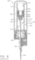
- the piston subassembly 10 slides along a cylinder inner wall (or “sleeve") 70 of the working cylinder 71.
- the bearing surfaces 52, 54, and 56 of piston top 20 contact the cylinder wall 70 during normal movement.
- the piston bottom 22 is slightly smaller in diameter and does not contact the cylinder wall.
- the piston is stopped by a stationary piston stop 84.
- a second piston subassembly for use in a fastener driving tool generally designated by the reference numeral 110 has two main halves: a piston top 120, and a piston bottom 122.
- the piston top 120 is constructed of a hard plastic, or other non-metallic material, preferably Delrin, whereas the piston bottom 122 is constructed of metal, preferably aluminum.
- the piston bottom is constructed with a stem that has a plurality of male threads 128, and the piston top has a threaded opening to receive the stem, in which the threads are female.
- the piston top is threadably attached using the piston bottom's male threads (see FIG. 6 ), such that both piston parts move together as a single piston subassembly.
- the two piston halves 120 and 122 may be attached to one another through any type of reliable mechanical connection, including a pin connector for example.
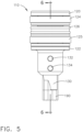
- piston subassembly 110 includes a cylindrical outer surface which has a circular cross-section, as can be seen in FIG. 7 .
- the center of the circular cross-section is located along a longitudinal axis of the piston, in which that longitudinal axis can be seen at "L" on FIG. 6 .
- the exact shape of the outer perimeter of the piston, and the exact shape of the corresponding inner surface of the cylinder sleeve do not necessarily have to be precisely circular. Instead, these surfaces could have other geometric shapes, so long as they are "mating shapes," and still fall within the principles of the technology disclosed herein. With regard to the disclosure presented herein, it will be assumed that the piston indeed has a circular cross-section, and therefore, the inner surface of the cylinder sleeve is also circular.
- this piston subassembly 110 is designed to move in a reciprocating manner along a direction that will be referred to herein as a longitudinal axis.
- a longitudinal axis is designated by the letter "L.”
- the piston top 120 has three circumferential recesses or grooves located on the outside surface of the piston.
- the upper groove holds a circular-shaped material 124 that comprises a porous media, such as a foam material, and the lower groove holds another circular-shaped material of porous media (e.g., foam material) 125.
- the middle groove holds a circular seal 126.
- the annular seal 126 is also sometimes referred to herein as a "perimeter seal,” since it runs around the outer perimeter of the piston.
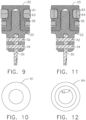
- porous media such as foam pieces
- the foam pieces could be arranged as a stack of foam pieces each having a smaller thickness, such as the pieces 61 and 63 on FIG. 9 .
- the top annular shape of this stack of smaller thickness foam pieces would have the shape depicted on FIG. 10 .
- the lower portion of the piston 22 also has side walls, which are not numbered on FIG. 4 .
- proximal can have a meaning of closely positioning one physical object with a second physical object, such that the two objects are perhaps adjacent to one another, although it is not necessarily required that there be no third object positioned therebetween.
- a "male locating structure” is to be positioned “proximal” to a “female locating structure.”
- this could mean that the two male and female structures are to be physically abutting one another, or this could mean that they are "mated” to one another by way of a particular size and shape that essentially keeps one structure oriented in a predetermined direction and at an X-Y (e.g., horizontal and vertical) position with respect to one another, regardless as to whether the two male and female structures actually touch one another along a continuous surface.
Landscapes
- Engineering & Computer Science (AREA)
- Mechanical Engineering (AREA)
- Physics & Mathematics (AREA)
- Fluid Mechanics (AREA)
- General Engineering & Computer Science (AREA)
- Chemical & Material Sciences (AREA)
- Combustion & Propulsion (AREA)
- Actuator (AREA)
- Portable Nailing Machines And Staplers (AREA)
- Percussive Tools And Related Accessories (AREA)
- Sliding-Contact Bearings (AREA)
- Pistons, Piston Rings, And Cylinders (AREA)
- Analytical Chemistry (AREA)
Claims (9)
- Treiberanordnung zur Verwendung in einem Elektrowerkzeug, wobei die Treiberanordnung Folgendes umfasst:einen beweglichen Kolben (10, 110), der eine obere Außenfläche (20, 120), eine untere Außenfläche (22, 122) und eine äußere Seitenwandfläche, die sich zwischen der oberen und unteren Außenfläche erstreckt, aufweist;einen Hohlzylinder (71) mit einer Innenfläche (70), welche die äußere Seitenwandfläche des Kolbens umgibt;einen beweglichen Treiber (90), der mit dem Kolben mechanisch verbunden ist;einen Führungskörper (36), der dazu ausgelegt ist, den Treiber zu führen, und dazu ausgelegt ist, ein Befestigungselement aufzunehmen, das vom Treiber zu einem Austrittsabschnitt des Führungskörpers zu treiben ist;eine erste Aussparung in der äußeren Seitenwandfläche des Kolbens undein poröses Medium (24, 124), das in der ersten Aussparung entlang der äußeren Seitenwandfläche des Kolbens positioniert ist und ein darin gespeichertes flüssiges Schmieröl enthält, wobei das poröse Medium dazu ausgelegt ist, das flüssige Schmieröl auf die Innenfläche (70) des Hohlzylinders (71) abzugeben; undein Gleitmittel, das zuvor auf die Innenfläche (70) des Hohlzylinders (71) aufgebracht wurde;wobei: sowohl das flüssige Schmieröl als auch das Gleitmittel zumindest einen Abschnitt der Innenfläche (70) des Hohlzylinders (71) in der Nähe der äußeren Seitenwandfläche des Kolbens (10, 110) schmieren, während sich der Kolben durch den Hohlzylinder bewegt.
- Treiberanordnung nach Anspruch 1, ferner umfassend:eine zweite Aussparung in der äußeren Seitenwandfläche des Kolbens, die sich in Bezug zur ersten Aussparung entlang der äußeren Seitenwandfläche des Kolbens an einer anderen Position befindet; undeine Umfangsdichtung (26, 126), die in der zweiten Aussparung positioniert ist.
- Treiberanordnung nach Anspruch 2,
wobei:die Umfangsdichtung (26, 126) die Innenfläche (70) des Hohlzylinders (71) berührt, während sich der Kolben (10, 110) durch den Zylinder auf und ab bewegt; unddie Umfangsdichtung (26, 126) verhindert, dass sich ein Großteil des flüssigen Schmieröls während eines Arbeitszyklus der Auf- und Abbewegung des Kolbens an der zweiten Aussparung in der äußeren Seitenwandfläche des Kolbens (10, 110) vorbei bewegt. - Treiberanordnung nach Anspruch 3, ferner umfassend:eine Hauptspeicherkammer (74), die dazu ausgelegt ist, ein druckbeaufschlagtes Gas zu enthalten;wobei:
der Zylinder (71) ein variables Verdrängungsvolumen auf einer ersten Seite des Kolbens (10, 110) aufweist, das mit der Hauptspeicherkammer (74) pneumatisch verbunden ist, und wobei der Zylinder (71) ein variables Entlüftungsvolumen auf einer zweiten, entgegengesetzten Seite des Kolbens (10, 110) aufweist, das mit der Außenumgebung pneumatisch verbunden ist. - Treiberanordnung zur Verwendung in einem Elektrowerkzeug, wobei die Treiberanordnung Folgendes umfasst:einen beweglichen Kolben (10, 110), der eine obere Außenfläche (20, 120), eine untere Außenfläche (22, 122) und eine äußere Seitenwandfläche, die sich zwischen der oberen und unteren Außenfläche erstreckt, aufweist;einen Hohlzylinder (71) mit einer Innenfläche (70), welche die äußere Seitenwandfläche des Kolbens umgibt;einen beweglichen Treiber (90), der mit dem Kolben mechanisch verbunden ist;einen Führungskörper (36), der dazu ausgelegt ist, den Treiber zu führen, und dazu ausgelegt ist, ein Befestigungselement aufzunehmen, das vom Treiber zu einem Austrittsabschnitt des Führungskörpers zu treiben ist;eine erste Aussparung in der äußeren Seitenwandfläche des Kolbens;ein erstes poröses Medium (24, 124), das in der ersten Aussparung positioniert ist;eine zweite Aussparung in der äußeren Seitenwandfläche des Kolbens, die sich in Bezug zur ersten Aussparung entlang der äußeren Seitenwandfläche des Kolbens an einer anderen Position befindet;ein zweites poröses Medium (125), das in der zweiten Aussparung positioniert ist;wobei das erste poröse Medium (24, 124) und/oder das zweite poröse Medium (125) ein darin gespeicherte flüssiges Schmieröl enthält/enthalten, wobei das poröse Medium dazu ausgelegt ist, das flüssige Schmieröl auf die Innenfläche (70) des Hohlzylinders (71) abzugeben; undein Gleitmittel, das zuvor auf die Innenfläche (70) des Hohlzylinders (71) aufgebracht wurde;wobei: sowohl das flüssige Schmieröl als auch das Gleitmittel zumindest einen Abschnitt der Innenfläche (70) des Hohlzylinders (71) in der Nähe der äußeren Seitenwandfläche des Kolbens (10, 110) schmieren, während sich der Kolben durch den Hohlzylinder bewegt.
- Treiberanordnung nach Anspruch 5, ferner umfassend:eine dritte Aussparung in der äußeren Seitenwandfläche des Kolbens, die sich entlang der äußeren Seitenwandfläche des Kolbens an einer anderen Position als die erste und zweite Aussparung befindet; undeine Umfangsdichtung (26, 126), die in der dritten Aussparung positioniert ist.
- Treiberanordnung nach Anspruch 6,
wobei:die Umfangsdichtung (26, 126) die Innenfläche (70) des Hohlzylinders (71) berührt, während sich der Kolben (10, 110) durch den Zylinder (71) auf und ab bewegt; unddie Umfangsdichtung (26, 126) verhindert, dass sich ein Großteil des flüssigen Schmieröls während eines Arbeitszyklus der Auf- und Abbewegung des Kolbens an der dritten Aussparung in der äußeren Seitenwandfläche vorbei bewegt. - Treiberanordnung nach Anspruch 7, ferner umfassend:eine Hauptspeicherkammer (74), die dazu ausgelegt ist, ein druckbeaufschlagtes Gas zu enthalten;wobei:der Zylinder (71) ein variables Verdrängungsvolumen auf einer ersten Seite des Kolbens (76) aufweist, das mit der Hauptspeicherkammer (74) mit druckbeaufschlagtem Gas pneumatisch verbunden ist, und wobei der Zylinder (71) ein variables Entlüftungsvolumen auf einer zweiten, entgegengesetzten Seite des Kolbens (75) aufweist, das mit der Außenumgebung pneumatisch verbunden ist;
undnicht verhindert wird, dass sich das flüssige Schmieröl zur Hauptspeicherkammer (74) bewegt, wo es in späteren Arbeitszyklen wiederverwendet wird. - Treiberanordnung nach Anspruch 8, wobei:die erste Aussparung und das erste poröse Medium (24, 124) in der Nähe der ersten Seite des Kolbens (20, 120) positioniert sind;die zweite Aussparung und das zweite poröse Medium (125) in der Nähe der zweiten Seite des Kolbens (22, 122) positioniert sind unddie dritte Aussparung und die Umfangsdichtung (26, 126) entlang der Außenfläche des Kolbens zwischen der ersten und zweiten Aussparung positioniert sind.
Applications Claiming Priority (2)
| Application Number | Priority Date | Filing Date | Title |
|---|---|---|---|
| US201862746941P | 2018-10-17 | 2018-10-17 | |
| PCT/US2019/056422 WO2020081620A1 (en) | 2018-10-17 | 2019-10-16 | Working cylinder for power tool with piston lubricating system |
Publications (3)
| Publication Number | Publication Date |
|---|---|
| EP3867017A1 EP3867017A1 (de) | 2021-08-25 |
| EP3867017A4 EP3867017A4 (de) | 2022-07-20 |
| EP3867017B1 true EP3867017B1 (de) | 2025-04-09 |
Family
ID=70280370
Family Applications (1)
| Application Number | Title | Priority Date | Filing Date |
|---|---|---|---|
| EP19873438.6A Active EP3867017B1 (de) | 2018-10-17 | 2019-10-16 | Arbeitszylinder für elektrowerkzeug mit kolbenschmiersystem |
Country Status (8)
| Country | Link |
|---|---|
| US (1) | US11413734B2 (de) |
| EP (1) | EP3867017B1 (de) |
| JP (1) | JP7162128B2 (de) |
| AU (2) | AU2019360114B2 (de) |
| CA (2) | CA3111568C (de) |
| FI (1) | FI3867017T3 (de) |
| NZ (1) | NZ773405A (de) |
| WO (1) | WO2020081620A1 (de) |
Families Citing this family (12)
| Publication number | Priority date | Publication date | Assignee | Title |
|---|---|---|---|---|
| US10843318B2 (en) * | 2015-04-30 | 2020-11-24 | Koki Holdings Co., Ltd. | Fastener driving machine |
| WO2021195188A1 (en) | 2020-03-25 | 2021-09-30 | Milwaukee Electric Tool Corporation | Powered fastener driver |
| US11712790B2 (en) * | 2020-04-14 | 2023-08-01 | Kyocera Senco Industrial Tools, Inc. | Pneumatic microfastener driving tool |
| AU2021267838B2 (en) | 2020-05-07 | 2024-03-21 | Kyocera Senco Industrial Tools, Inc. | Power driving tool with latch position sensor |
| US11819989B2 (en) * | 2020-07-07 | 2023-11-21 | Techtronic Cordless Gp | Powered fastener driver |
| WO2022209078A1 (ja) * | 2021-03-31 | 2022-10-06 | 工機ホールディングス株式会社 | 作業機 |
| CA3167425A1 (en) | 2021-07-16 | 2023-01-16 | Techtronic Cordless Gp | Powered fastener driver |
| WO2023080192A1 (ja) * | 2021-11-08 | 2023-05-11 | 工機ホールディングス株式会社 | 作業機 |
| EP4482651A1 (de) | 2022-02-21 | 2025-01-01 | Kyocera Senco Industrial Tools, Inc. | Magazinhalterführung für ein werkzeug zum eintreiben von befestigungsmitteln |
| JP2025025662A (ja) * | 2023-08-10 | 2025-02-21 | 工機ホールディングス株式会社 | 作業機 |
| JP2025093093A (ja) * | 2023-12-11 | 2025-06-23 | 株式会社マキタ | 打ち込み工具 |
| CN120027114B (zh) * | 2025-04-21 | 2025-07-18 | 湖南协力液压有限公司 | 一种带自润滑系统的油缸 |
Family Cites Families (74)
| Publication number | Priority date | Publication date | Assignee | Title |
|---|---|---|---|---|
| US860536A (en) | 1906-11-24 | 1907-07-16 | Robert W Ellingham | Roller-pinion. |
| US1774967A (en) | 1929-08-03 | 1930-09-02 | James T Ellis | Piston for slush pumps |
| US2026409A (en) * | 1931-12-31 | 1935-12-31 | Harley T Wheeler | Packing ring |
| US2419192A (en) * | 1944-07-18 | 1947-04-22 | Oscar W Giese | Piston and cylinder construction |
| US2575455A (en) | 1945-12-12 | 1951-11-20 | Bocjl Corp | Impact tool |
| US2635932A (en) | 1949-03-28 | 1953-04-21 | Heusser Wilfrid | Piston ring assembly for the pistons of internal-combustion engines |
| GB755685A (en) * | 1953-07-20 | 1956-08-22 | Neville Rupert Anderson | Improvements in or relating to grease-lubricated air-operated piston and cylinder devices |
| US2814041A (en) | 1955-03-14 | 1957-11-26 | Emmett L Haley | Power devices |
| US2797971A (en) * | 1955-11-14 | 1957-07-02 | Cleveland Pneumatic Tool Co | Sectional fluid seal |
| US2933290A (en) | 1958-07-03 | 1960-04-19 | Jr Harold E Ryder | Rack shaft locking means |
| US3150488A (en) | 1961-11-22 | 1964-09-29 | Emmett L Haley | Power devices |
| FR1355560A (fr) * | 1962-11-30 | 1964-03-20 | Bande de pointes, son procédé de fabrication, et appareil de clouage utilisant detelles pointes | |
| US3276417A (en) * | 1965-08-11 | 1966-10-04 | Louis C Flowers | Pressure indicating apparatus for a pneumatic tire |
| DE1510164A1 (de) | 1965-09-07 | 1970-02-26 | Drahtseilwerk Wurzen Veb | Vorrichtung zum Vorformen von Litzen oder Draehten fuer Drahtseile |
| US3589588A (en) | 1969-07-14 | 1971-06-29 | George O Vasku | Impact tool |
| US3661216A (en) * | 1969-09-10 | 1972-05-09 | Nippon Pneumatic Mfg | Impact air driven tool |
| DE2026272C3 (de) * | 1970-05-29 | 1975-03-27 | Maschinenfabrik Augsburg-Nuernberg Ag, Zweigniederl. Nuernberg, 8500 Nuernberg | Kolben für Brennkraftmaschinen |
| JPS519199B2 (de) | 1972-04-03 | 1976-03-24 | ||
| US3847322A (en) | 1973-09-10 | 1974-11-12 | H Smith | Power driven hammer |
| US4005763A (en) * | 1975-03-19 | 1977-02-01 | Wallis Bernard J | Lubricating means for gas-operated cylinders |
| GB1559571A (en) | 1976-09-24 | 1980-01-23 | Avon Ind Polymers | Piston means for piston cylinder arrangements |
| US4215808A (en) | 1978-12-22 | 1980-08-05 | Sollberger Roger W | Portable electric fastener driving apparatus |
| IT8221968U1 (it) * | 1982-05-21 | 1983-11-21 | Frosi Grazia | Stantuffo perfezionato, in particolare per pompe di travaso di aeriformi |
| US4986164A (en) | 1983-06-13 | 1991-01-22 | Senco Products, Inc. | Pneumatic gun having improved firing valve |
| US4530455A (en) | 1983-08-11 | 1985-07-23 | Senco Products, Inc. | Piston and driver |
| US4557351A (en) * | 1984-07-25 | 1985-12-10 | Denice C. Reich Inc. | Lubrication system for a walking beam compressor |
| DE3527997A1 (de) * | 1985-08-03 | 1987-02-12 | Bauer Fritz & Soehne Ohg | Gasfeder |
| US4679719A (en) | 1985-12-27 | 1987-07-14 | Senco Products, Inc. | Electronic control for a pneumatic fastener driving tool |
| US4741518A (en) | 1986-08-26 | 1988-05-03 | Wallis Bernard J | Self contained gas spring interchangeable with coil spring |
| DE8711784U1 (de) | 1987-08-31 | 1987-11-05 | Demba Metallwarenfabrik GmbH, 2072 Bargteheide | Elektrisch betriebenes Eintreibgerät |
| AU637367B2 (en) | 1990-04-24 | 1993-05-27 | Regitar Power Tools Co Ltd | A transmission mechanism for an electric stapling gun |
| DE4030869A1 (de) * | 1990-09-29 | 1992-04-02 | Suspa Compart Ag | Reibungsdaempfer |
| US5199627A (en) | 1991-03-29 | 1993-04-06 | Christensen Jeffrey M | Self powered magazine hammer |
| JP2568736Y2 (ja) | 1993-12-06 | 1998-04-15 | マックス株式会社 | 可搬形電動ステープル打機 |
| WO1996012591A1 (en) | 1994-10-21 | 1996-05-02 | Senco Products, Inc. | Pneumatic fastener driving tool and an electronic control system therefor |
| US5557905A (en) | 1995-01-31 | 1996-09-24 | Harding; Kay J. | Bit for administering animal medication |
| JP3676879B2 (ja) | 1995-07-25 | 2005-07-27 | 株式会社マキタ | 締結具打込み工具 |
| JP3133005B2 (ja) | 1996-12-25 | 2001-02-05 | 加茂精工株式会社 | 回転運動と直線運動の変換装置 |
| US5927585A (en) | 1997-12-17 | 1999-07-27 | Senco Products, Inc. | Electric multiple impact fastener driving tool |
| US6568313B2 (en) * | 2001-03-07 | 2003-05-27 | Smc Kabushiki Kaisha | Fluid pressure cylinder apparatus |
| WO2003000946A1 (en) | 2001-06-26 | 2003-01-03 | Kabushiki Kaisha Toyota Chuo Kenkyusho | Sliding member and method for manufacture thereof |
| US6685193B2 (en) * | 2001-08-30 | 2004-02-03 | Illinois Tool Works Inc. | Self lubricating, non-sealing piston ring for an internal combustion fastener driving tool |
| DE10222338A1 (de) | 2002-05-21 | 2003-12-04 | Hilti Ag | Brennkraftbetriebenes Setzgerät |
| WO2004011201A1 (fr) | 2002-07-25 | 2004-02-05 | Yih Kai Enterprise Co.,Ltd. | Outil de clouage a main |
| US6533156B1 (en) | 2002-09-09 | 2003-03-18 | We-Chou Chang | Pneumatic nail gun |
| DE10325920B4 (de) | 2003-06-07 | 2005-09-01 | Hilti Ag | Über expandierbare Gase antreibbares Setzgerät |
| ATE394200T1 (de) | 2004-04-02 | 2008-05-15 | Black & Decker Inc | Befestigungswerkzeug mit moduswahlschalter |
| US20050279802A1 (en) * | 2004-06-14 | 2005-12-22 | Moeller Larry M | Seal for portable fastener driving tool |
| US7040521B2 (en) | 2004-09-01 | 2006-05-09 | Illinois Tool Works Inc. | Gas driven actuation feed tube for combustion powered fastener-driving tool |
| US20060180631A1 (en) | 2005-02-16 | 2006-08-17 | Chris Pedicini | Electric motor driven energy storage device for impacting |
| US7225962B2 (en) | 2005-02-18 | 2007-06-05 | Illinois Tool Works Inc. | Nail advancement systems for nail arrays disposed within nailing tool magazines |
| US7494037B2 (en) | 2005-05-12 | 2009-02-24 | Stanley Fastening Systems, L.P. | Fastener driving device |
| DE102005000107B4 (de) | 2005-08-25 | 2014-03-13 | Hilti Aktiengesellschaft | Pneumatisch betriebenes Setzgerät |
| US20070144753A1 (en) * | 2005-12-22 | 2007-06-28 | Microtorq, L.L.C. | Transducerized rotary tool |
| US7225961B1 (en) | 2006-05-11 | 2007-06-05 | Samson Power Tool Co., Ltd. | Air path arrangement for pneumatic nail gun |
| WO2007142997A2 (en) | 2006-05-31 | 2007-12-13 | Stanley Fastening Systems, L.P. | Fastener driving device |
| JP2008068356A (ja) | 2006-09-14 | 2008-03-27 | Hitachi Koki Co Ltd | 電動式打込機 |
| US8258086B2 (en) * | 2006-12-01 | 2012-09-04 | Henkel Corporation | Anti-seize composition with nano-sized lubricating solid particles |
| US20080190986A1 (en) | 2007-02-09 | 2008-08-14 | Chin-Hsiung Chang | Electric Nailing Mechanism |
| US8875969B2 (en) | 2007-02-09 | 2014-11-04 | Tricord Solutions, Inc. | Fastener driving apparatus |
| US8011547B2 (en) | 2007-10-05 | 2011-09-06 | Senco Brands, Inc. | Fastener driving tool using a gas spring |
| US8763874B2 (en) | 2007-10-05 | 2014-07-01 | Senco Brands, Inc. | Gas spring fastener driving tool with improved lifter and latch mechanisms |
| US8313545B2 (en) * | 2007-10-16 | 2012-11-20 | Illinois Tool Works Inc. | Air filter assembly for combustion tool |
| DE102008032791A1 (de) | 2008-07-11 | 2010-01-14 | Wacker Neuson Se | Bohr- und/oder Schlaghammer mit Nachschmiervorrichtung |
| JP5948216B2 (ja) * | 2011-10-25 | 2016-07-06 | 株式会社Ihi | ピストンリングの製造方法 |
| GB201216905D0 (en) * | 2012-09-21 | 2012-11-07 | Black & Decker Inc | A hammer drill |
| EP3000560A1 (de) | 2014-09-25 | 2016-03-30 | HILTI Aktiengesellschaft | Eintreibgerät mit Gasfeder |
| US10518396B2 (en) * | 2014-12-23 | 2019-12-31 | Tti (Macao Commercial Offshore) Limited | Drive blade lubrication assembly and powered fastener driver containing the same |
| NZ735578A (en) | 2015-03-30 | 2019-03-29 | Senco Brands Inc | Lift mechanism for framing nailer |
| WO2017056810A1 (ja) | 2015-09-30 | 2017-04-06 | 日立工機株式会社 | 打込機 |
| US20170080554A1 (en) | 2016-11-30 | 2017-03-23 | Caterpillar Inc. | Hydraulic hammer assembly |
| CN108779407A (zh) * | 2016-12-19 | 2018-11-09 | 株式会社Vab | 润滑油添加剂、润滑油、润滑脂组合物、燃料油添加剂、燃料油及油泥抑制方法 |
| FI3558595T3 (fi) | 2016-12-22 | 2023-12-14 | Kyocera Senco Industrial Tools Inc | Kiinnittimen käyttötyökalu, jossa on käyttölaitteen paikka-anturit |
| CA3072552A1 (en) * | 2017-08-09 | 2019-02-14 | Mainspring Energy, Inc. | Piston seal with solid lubricant applicator |
-
2019
- 2019-10-16 EP EP19873438.6A patent/EP3867017B1/de active Active
- 2019-10-16 AU AU2019360114A patent/AU2019360114B2/en active Active
- 2019-10-16 CA CA3111568A patent/CA3111568C/en active Active
- 2019-10-16 WO PCT/US2019/056422 patent/WO2020081620A1/en not_active Ceased
- 2019-10-16 CA CA3204017A patent/CA3204017A1/en active Pending
- 2019-10-16 US US16/654,315 patent/US11413734B2/en active Active
- 2019-10-16 FI FIEP19873438.6T patent/FI3867017T3/fi active
- 2019-10-16 NZ NZ773405A patent/NZ773405A/en unknown
- 2019-10-16 JP JP2021514962A patent/JP7162128B2/ja active Active
-
2022
- 2022-10-21 AU AU2022256196A patent/AU2022256196B2/en active Active
Also Published As
| Publication number | Publication date |
|---|---|
| JP2021535991A (ja) | 2021-12-23 |
| EP3867017A1 (de) | 2021-08-25 |
| CA3111568C (en) | 2023-08-22 |
| JP7162128B2 (ja) | 2022-10-27 |
| CA3111568A1 (en) | 2020-04-23 |
| AU2022256196A1 (en) | 2022-11-24 |
| CA3204017A1 (en) | 2020-04-23 |
| AU2019360114B2 (en) | 2022-08-11 |
| US20200122308A1 (en) | 2020-04-23 |
| NZ773405A (en) | 2023-07-28 |
| FI3867017T3 (fi) | 2025-05-27 |
| AU2019360114A1 (en) | 2021-03-25 |
| AU2022256196B2 (en) | 2024-08-15 |
| EP3867017A4 (de) | 2022-07-20 |
| US11413734B2 (en) | 2022-08-16 |
| WO2020081620A1 (en) | 2020-04-23 |
Similar Documents
| Publication | Publication Date | Title |
|---|---|---|
| AU2022256196B2 (en) | Working cylinder for power tool with piston lubricating system | |
| US12194607B2 (en) | Working cylinder for power tool with piston lubricating system | |
| JP6938256B2 (ja) | 打ち込み工具 | |
| US12194606B2 (en) | Working machine | |
| JP5621990B2 (ja) | 摺動部材 | |
| EP2806178A1 (de) | Gleitelement | |
| KR101402818B1 (ko) | 윤활유 순환 시스템을 구비하는 전동 해머 드릴 | |
| EP1270958A1 (de) | Hydraulikzylinder | |
| US6431053B1 (en) | Piston for a swashplate reciprocating compressor | |
| CN108328010B (zh) | 用于密封容器的密封机的驱出装置的驱出头 | |
| US5199345A (en) | Piston compressor for the oilfree compression of a gas | |
| CN101280753A (zh) | 一种柴油机喷油泵顶杆部件 | |
| JP4968274B2 (ja) | 燃料供給ポンプ | |
| JP2006275002A (ja) | 内燃機関用ピストン | |
| JP3929952B2 (ja) | 案内装置の潤滑装置 | |
| US20100054967A1 (en) | High-Pressure Fuel Pump | |
| JP5528688B2 (ja) | ピストン式圧縮機 | |
| CN215333980U (zh) | 一种便于注油的精密导轨 | |
| JP3137503U (ja) | 潤滑改善形状カム類 | |
| JP7780102B2 (ja) | 作業機 | |
| CN201198802Y (zh) | 一种柴油机喷油泵顶杆部件 | |
| JPH0663516U (ja) | 自動給油装置付きチェーン | |
| KR20160053022A (ko) | 비운전시 윤활 기능이 부가된 크로스헤드 베어링 | |
| KR960008053A (ko) | 밀폐형 압축기 | |
| JP2007205233A (ja) | 斜板式圧縮機 |
Legal Events
| Date | Code | Title | Description |
|---|---|---|---|
| STAA | Information on the status of an ep patent application or granted ep patent |
Free format text: STATUS: THE INTERNATIONAL PUBLICATION HAS BEEN MADE |
|
| PUAI | Public reference made under article 153(3) epc to a published international application that has entered the european phase |
Free format text: ORIGINAL CODE: 0009012 |
|
| STAA | Information on the status of an ep patent application or granted ep patent |
Free format text: STATUS: REQUEST FOR EXAMINATION WAS MADE |
|
| 17P | Request for examination filed |
Effective date: 20210301 |
|
| AK | Designated contracting states |
Kind code of ref document: A1 Designated state(s): AL AT BE BG CH CY CZ DE DK EE ES FI FR GB GR HR HU IE IS IT LI LT LU LV MC MK MT NL NO PL PT RO RS SE SI SK SM TR |
|
| DAV | Request for validation of the european patent (deleted) | ||
| DAX | Request for extension of the european patent (deleted) | ||
| A4 | Supplementary search report drawn up and despatched |
Effective date: 20220617 |
|
| RIC1 | Information provided on ipc code assigned before grant |
Ipc: B25D 17/26 20060101ALI20220611BHEP Ipc: B25D 17/00 20060101ALI20220611BHEP Ipc: B25D 9/00 20060101ALI20220611BHEP Ipc: B25F 5/00 20060101ALI20220611BHEP Ipc: B25C 1/00 20060101AFI20220611BHEP |
|
| GRAP | Despatch of communication of intention to grant a patent |
Free format text: ORIGINAL CODE: EPIDOSNIGR1 |
|
| STAA | Information on the status of an ep patent application or granted ep patent |
Free format text: STATUS: GRANT OF PATENT IS INTENDED |
|
| INTG | Intention to grant announced |
Effective date: 20240612 |
|
| RIN1 | Information on inventor provided before grant (corrected) |
Inventor name: KABBES, ANTHONY D. Inventor name: MCCARDLE, THOMAS A. Inventor name: BRADLEY, DAVID D. |
|
| GRAJ | Information related to disapproval of communication of intention to grant by the applicant or resumption of examination proceedings by the epo deleted |
Free format text: ORIGINAL CODE: EPIDOSDIGR1 |
|
| STAA | Information on the status of an ep patent application or granted ep patent |
Free format text: STATUS: REQUEST FOR EXAMINATION WAS MADE |
|
| INTC | Intention to grant announced (deleted) | ||
| GRAP | Despatch of communication of intention to grant a patent |
Free format text: ORIGINAL CODE: EPIDOSNIGR1 |
|
| STAA | Information on the status of an ep patent application or granted ep patent |
Free format text: STATUS: GRANT OF PATENT IS INTENDED |
|
| INTG | Intention to grant announced |
Effective date: 20241128 |
|
| GRAS | Grant fee paid |
Free format text: ORIGINAL CODE: EPIDOSNIGR3 |
|
| GRAA | (expected) grant |
Free format text: ORIGINAL CODE: 0009210 |
|
| STAA | Information on the status of an ep patent application or granted ep patent |
Free format text: STATUS: THE PATENT HAS BEEN GRANTED |
|
| AK | Designated contracting states |
Kind code of ref document: B1 Designated state(s): AL AT BE BG CH CY CZ DE DK EE ES FI FR GB GR HR HU IE IS IT LI LT LU LV MC MK MT NL NO PL PT RO RS SE SI SK SM TR |
|
| REG | Reference to a national code |
Ref country code: GB Ref legal event code: FG4D |
|
| REG | Reference to a national code |
Ref country code: CH Ref legal event code: EP |
|
| REG | Reference to a national code |
Ref country code: DE Ref legal event code: R096 Ref document number: 602019068543 Country of ref document: DE |
|
| REG | Reference to a national code |
Ref country code: IE Ref legal event code: FG4D |
|
| REG | Reference to a national code |
Ref country code: FI Ref legal event code: FGE |
|
| REG | Reference to a national code |
Ref country code: SE Ref legal event code: TRGR |
|
| REG | Reference to a national code |
Ref country code: NL Ref legal event code: MP Effective date: 20250409 |
|
| PG25 | Lapsed in a contracting state [announced via postgrant information from national office to epo] |
Ref country code: NL Free format text: LAPSE BECAUSE OF FAILURE TO SUBMIT A TRANSLATION OF THE DESCRIPTION OR TO PAY THE FEE WITHIN THE PRESCRIBED TIME-LIMIT Effective date: 20250409 |
|
| REG | Reference to a national code |
Ref country code: AT Ref legal event code: MK05 Ref document number: 1783149 Country of ref document: AT Kind code of ref document: T Effective date: 20250409 |
|
| PG25 | Lapsed in a contracting state [announced via postgrant information from national office to epo] |
Ref country code: ES Free format text: LAPSE BECAUSE OF FAILURE TO SUBMIT A TRANSLATION OF THE DESCRIPTION OR TO PAY THE FEE WITHIN THE PRESCRIBED TIME-LIMIT Effective date: 20250409 Ref country code: PT Free format text: LAPSE BECAUSE OF FAILURE TO SUBMIT A TRANSLATION OF THE DESCRIPTION OR TO PAY THE FEE WITHIN THE PRESCRIBED TIME-LIMIT Effective date: 20250811 |
|
| REG | Reference to a national code |
Ref country code: LT Ref legal event code: MG9D |
|
| PG25 | Lapsed in a contracting state [announced via postgrant information from national office to epo] |
Ref country code: GR Free format text: LAPSE BECAUSE OF FAILURE TO SUBMIT A TRANSLATION OF THE DESCRIPTION OR TO PAY THE FEE WITHIN THE PRESCRIBED TIME-LIMIT Effective date: 20250710 Ref country code: NO Free format text: LAPSE BECAUSE OF FAILURE TO SUBMIT A TRANSLATION OF THE DESCRIPTION OR TO PAY THE FEE WITHIN THE PRESCRIBED TIME-LIMIT Effective date: 20250709 |
|
| PG25 | Lapsed in a contracting state [announced via postgrant information from national office to epo] |
Ref country code: PL Free format text: LAPSE BECAUSE OF FAILURE TO SUBMIT A TRANSLATION OF THE DESCRIPTION OR TO PAY THE FEE WITHIN THE PRESCRIBED TIME-LIMIT Effective date: 20250409 |
|
| PG25 | Lapsed in a contracting state [announced via postgrant information from national office to epo] |
Ref country code: BG Free format text: LAPSE BECAUSE OF FAILURE TO SUBMIT A TRANSLATION OF THE DESCRIPTION OR TO PAY THE FEE WITHIN THE PRESCRIBED TIME-LIMIT Effective date: 20250409 |
|
| PGFP | Annual fee paid to national office [announced via postgrant information from national office to epo] |
Ref country code: GB Payment date: 20250828 Year of fee payment: 7 |
|
| PG25 | Lapsed in a contracting state [announced via postgrant information from national office to epo] |
Ref country code: HR Free format text: LAPSE BECAUSE OF FAILURE TO SUBMIT A TRANSLATION OF THE DESCRIPTION OR TO PAY THE FEE WITHIN THE PRESCRIBED TIME-LIMIT Effective date: 20250409 |
|
| PG25 | Lapsed in a contracting state [announced via postgrant information from national office to epo] |
Ref country code: AT Free format text: LAPSE BECAUSE OF FAILURE TO SUBMIT A TRANSLATION OF THE DESCRIPTION OR TO PAY THE FEE WITHIN THE PRESCRIBED TIME-LIMIT Effective date: 20250409 |
|
| PGFP | Annual fee paid to national office [announced via postgrant information from national office to epo] |
Ref country code: FR Payment date: 20250908 Year of fee payment: 7 |
|
| PGFP | Annual fee paid to national office [announced via postgrant information from national office to epo] |
Ref country code: SE Payment date: 20250910 Year of fee payment: 7 |
|
| PG25 | Lapsed in a contracting state [announced via postgrant information from national office to epo] |
Ref country code: RS Free format text: LAPSE BECAUSE OF FAILURE TO SUBMIT A TRANSLATION OF THE DESCRIPTION OR TO PAY THE FEE WITHIN THE PRESCRIBED TIME-LIMIT Effective date: 20250709 |
|
| PG25 | Lapsed in a contracting state [announced via postgrant information from national office to epo] |
Ref country code: IS Free format text: LAPSE BECAUSE OF FAILURE TO SUBMIT A TRANSLATION OF THE DESCRIPTION OR TO PAY THE FEE WITHIN THE PRESCRIBED TIME-LIMIT Effective date: 20250809 |
|
| PG25 | Lapsed in a contracting state [announced via postgrant information from national office to epo] |
Ref country code: LV Free format text: LAPSE BECAUSE OF FAILURE TO SUBMIT A TRANSLATION OF THE DESCRIPTION OR TO PAY THE FEE WITHIN THE PRESCRIBED TIME-LIMIT Effective date: 20250409 |
|
| PGFP | Annual fee paid to national office [announced via postgrant information from national office to epo] |
Ref country code: DE Payment date: 20250902 Year of fee payment: 7 |
|
| REG | Reference to a national code |
Ref country code: DE Ref legal event code: R097 Ref document number: 602019068543 Country of ref document: DE |
|
| PG25 | Lapsed in a contracting state [announced via postgrant information from national office to epo] |
Ref country code: SM Free format text: LAPSE BECAUSE OF FAILURE TO SUBMIT A TRANSLATION OF THE DESCRIPTION OR TO PAY THE FEE WITHIN THE PRESCRIBED TIME-LIMIT Effective date: 20250409 Ref country code: DK Free format text: LAPSE BECAUSE OF FAILURE TO SUBMIT A TRANSLATION OF THE DESCRIPTION OR TO PAY THE FEE WITHIN THE PRESCRIBED TIME-LIMIT Effective date: 20250409 |
|
| PGFP | Annual fee paid to national office [announced via postgrant information from national office to epo] |
Ref country code: FI Payment date: 20251014 Year of fee payment: 7 |
|
| PG25 | Lapsed in a contracting state [announced via postgrant information from national office to epo] |
Ref country code: CZ Free format text: LAPSE BECAUSE OF FAILURE TO SUBMIT A TRANSLATION OF THE DESCRIPTION OR TO PAY THE FEE WITHIN THE PRESCRIBED TIME-LIMIT Effective date: 20250409 |
|
| PG25 | Lapsed in a contracting state [announced via postgrant information from national office to epo] |
Ref country code: EE Free format text: LAPSE BECAUSE OF FAILURE TO SUBMIT A TRANSLATION OF THE DESCRIPTION OR TO PAY THE FEE WITHIN THE PRESCRIBED TIME-LIMIT Effective date: 20250409 |
|
| PG25 | Lapsed in a contracting state [announced via postgrant information from national office to epo] |
Ref country code: RO Free format text: LAPSE BECAUSE OF FAILURE TO SUBMIT A TRANSLATION OF THE DESCRIPTION OR TO PAY THE FEE WITHIN THE PRESCRIBED TIME-LIMIT Effective date: 20250409 Ref country code: SK Free format text: LAPSE BECAUSE OF FAILURE TO SUBMIT A TRANSLATION OF THE DESCRIPTION OR TO PAY THE FEE WITHIN THE PRESCRIBED TIME-LIMIT Effective date: 20250409 |
|
| PG25 | Lapsed in a contracting state [announced via postgrant information from national office to epo] |
Ref country code: IT Free format text: LAPSE BECAUSE OF FAILURE TO SUBMIT A TRANSLATION OF THE DESCRIPTION OR TO PAY THE FEE WITHIN THE PRESCRIBED TIME-LIMIT Effective date: 20250409 |
|
| PLBE | No opposition filed within time limit |
Free format text: ORIGINAL CODE: 0009261 |
|
| STAA | Information on the status of an ep patent application or granted ep patent |
Free format text: STATUS: NO OPPOSITION FILED WITHIN TIME LIMIT |
|
| REG | Reference to a national code |
Ref country code: CH Ref legal event code: L10 Free format text: ST27 STATUS EVENT CODE: U-0-0-L10-L00 (AS PROVIDED BY THE NATIONAL OFFICE) Effective date: 20260218 |
|
| 26N | No opposition filed |
Effective date: 20260112 |