EP3867017B1 - Working cylinder for power tool with piston lubricating system - Google Patents
Working cylinder for power tool with piston lubricating system Download PDFInfo
- Publication number
- EP3867017B1 EP3867017B1 EP19873438.6A EP19873438A EP3867017B1 EP 3867017 B1 EP3867017 B1 EP 3867017B1 EP 19873438 A EP19873438 A EP 19873438A EP 3867017 B1 EP3867017 B1 EP 3867017B1
- Authority
- EP
- European Patent Office
- Prior art keywords
- piston
- recess
- side wall
- cylinder
- driver
- Prior art date
- Legal status (The legal status is an assumption and is not a legal conclusion. Google has not performed a legal analysis and makes no representation as to the accuracy of the status listed.)
- Active
Links
Images




Classifications
-
- B—PERFORMING OPERATIONS; TRANSPORTING
- B25—HAND TOOLS; PORTABLE POWER-DRIVEN TOOLS; MANIPULATORS
- B25C—HAND-HELD NAILING OR STAPLING TOOLS; MANUALLY OPERATED PORTABLE STAPLING TOOLS
- B25C1/00—Hand-held nailing tools; Nail feeding devices
- B25C1/04—Hand-held nailing tools; Nail feeding devices operated by fluid pressure, e.g. by air pressure
- B25C1/041—Hand-held nailing tools; Nail feeding devices operated by fluid pressure, e.g. by air pressure with fixed main cylinder
-
- B—PERFORMING OPERATIONS; TRANSPORTING
- B25—HAND TOOLS; PORTABLE POWER-DRIVEN TOOLS; MANIPULATORS
- B25C—HAND-HELD NAILING OR STAPLING TOOLS; MANUALLY OPERATED PORTABLE STAPLING TOOLS
- B25C1/00—Hand-held nailing tools; Nail feeding devices
- B25C1/04—Hand-held nailing tools; Nail feeding devices operated by fluid pressure, e.g. by air pressure
- B25C1/047—Mechanical details
-
- B—PERFORMING OPERATIONS; TRANSPORTING
- B25—HAND TOOLS; PORTABLE POWER-DRIVEN TOOLS; MANIPULATORS
- B25C—HAND-HELD NAILING OR STAPLING TOOLS; MANUALLY OPERATED PORTABLE STAPLING TOOLS
- B25C7/00—Accessories for nailing or stapling tools, e.g. supports
-
- F—MECHANICAL ENGINEERING; LIGHTING; HEATING; WEAPONS; BLASTING
- F15—FLUID-PRESSURE ACTUATORS; HYDRAULICS OR PNEUMATICS IN GENERAL
- F15B—SYSTEMS ACTING BY MEANS OF FLUIDS IN GENERAL; FLUID-PRESSURE ACTUATORS, e.g. SERVOMOTORS; DETAILS OF FLUID-PRESSURE SYSTEMS, NOT OTHERWISE PROVIDED FOR
- F15B15/00—Fluid-actuated devices for displacing a member from one position to another; Gearing associated therewith
- F15B15/08—Characterised by the construction of the motor unit
- F15B15/14—Characterised by the construction of the motor unit of the straight-cylinder type
- F15B15/1423—Component parts; Constructional details
- F15B15/1447—Pistons; Piston to piston rod assemblies
- F15B15/1452—Piston sealings
-
- F—MECHANICAL ENGINEERING; LIGHTING; HEATING; WEAPONS; BLASTING
- F16—ENGINEERING ELEMENTS AND UNITS; GENERAL MEASURES FOR PRODUCING AND MAINTAINING EFFECTIVE FUNCTIONING OF MACHINES OR INSTALLATIONS; THERMAL INSULATION IN GENERAL
- F16J—PISTONS; CYLINDERS; SEALINGS
- F16J1/00—Pistons; Trunk pistons; Plungers
- F16J1/08—Constructional features providing for lubrication
-
- B—PERFORMING OPERATIONS; TRANSPORTING
- B25—HAND TOOLS; PORTABLE POWER-DRIVEN TOOLS; MANIPULATORS
- B25C—HAND-HELD NAILING OR STAPLING TOOLS; MANUALLY OPERATED PORTABLE STAPLING TOOLS
- B25C1/00—Hand-held nailing tools; Nail feeding devices
- B25C1/06—Hand-held nailing tools; Nail feeding devices operated by electric power
-
- F—MECHANICAL ENGINEERING; LIGHTING; HEATING; WEAPONS; BLASTING
- F15—FLUID-PRESSURE ACTUATORS; HYDRAULICS OR PNEUMATICS IN GENERAL
- F15B—SYSTEMS ACTING BY MEANS OF FLUIDS IN GENERAL; FLUID-PRESSURE ACTUATORS, e.g. SERVOMOTORS; DETAILS OF FLUID-PRESSURE SYSTEMS, NOT OTHERWISE PROVIDED FOR
- F15B21/00—Common features of fluid actuator systems; Fluid-pressure actuator systems or details thereof, not covered by any other group of this subclass
- F15B21/04—Special measures taken in connection with the properties of the fluid
- F15B21/048—Arrangements for compressed air preparation, e.g. comprising air driers, air condensers, filters, lubricators or pressure regulators
-
- F—MECHANICAL ENGINEERING; LIGHTING; HEATING; WEAPONS; BLASTING
- F16—ENGINEERING ELEMENTS AND UNITS; GENERAL MEASURES FOR PRODUCING AND MAINTAINING EFFECTIVE FUNCTIONING OF MACHINES OR INSTALLATIONS; THERMAL INSULATION IN GENERAL
- F16J—PISTONS; CYLINDERS; SEALINGS
- F16J15/00—Sealings
- F16J15/16—Sealings between relatively-moving surfaces
- F16J15/162—Special parts or details relating to lubrication or cooling of the sealing itself
Definitions
- the technology disclosed herein relates generally to fastener driving tools and is particularly directed to such tools of the type which use pressurized air to drive a piston that, in turn, causes a driver blade to force a fastener into a target workpiece.
- Embodiments are specifically disclosed which use lubricant-saturated porous media, such as a foam material, surrounding a portion of the outside of a piston, inside a working cylinder, to continually lubricate and clean the piston and working cylinder, enhancing the performance over a greater lifetime of the tool.
- the upper material is non-metal and serves as guidance bearings against the cylinder wall that will not scratch the surface of the anodized cylinder.
- a driver assembly according to claim 1 is provided.
- connection and “coupled” and variations thereof are not restricted to physical or mechanical connections or couplings.
- communicated with and “in communications with” refer to two different physical or virtual elements that somehow pass signals or information between each other, whether that transfer of signals or information is direct or whether there are additional physical or virtual elements therebetween that are also involved in that passing of signals or information.
- first and second preceding an element name, e.g., first inlet, second inlet, etc., are used for identification purposes to distinguish between similar or related elements, results or concepts, and are not intended to necessarily imply order, nor are the terms “first” and “second” intended to preclude the inclusion of additional similar or related elements, results or concepts, unless otherwise indicated.
- a piston subassembly for use in a fastener driving tool generally designated by the reference numeral 10 has two main halves: a piston top 20, and a piston bottom 22.
- the piston top 20 is constructed of a hard plastic, or other non-metallic material, preferably Delrin, whereas the piston bottom 22 is constructed of metal, preferably aluminum.
- the piston bottom is constructed with a stem that has a plurality of male threads 28, and the piston top has a threaded opening to receive the stem, in which the threads are female.
- the piston top is threadably attached using the piston bottom's male threads (see FIG. 2 ), such that both piston parts move together as a single piston subassembly 10.
- the piston design described above is merely a preferred embodiment for constructing the overall piston, and other two-piece piston designs could be used without departing from the principles of this technology.
- the two piston halves 20 and 22 may be attached to one another through any type of reliable mechanical connection, including a pin connector.
- the two piston halves 20, 22 could be constrained without mechanical fasteners so that they always move together.
- the gas pressure of the working cylinder 71 (see FIG. 4 ) will tend to keep the top piston half 20 firmly pressed against the bottom piston half 22 under almost all circumstances of tool operation.
- a driver 90 (see FIG. 3 ) has an upper attachment portion 30 that is installed during manufacture into an opening in the piston bottom half 22.
- the piston bottom 22 exhibits two through openings 42 and 44 that are transverse to the driver opening.
- Two connecting pins 32 and 34 are used to secure the driver, at the driver upper portion 30, to the piston bottom 22. It will be understood that the various directional nomenclature provided above is with respect to the illustration of FIG. 2 , and the first embodiment can be used in many other angular positions, without departing from the principles of this technology. The use of these two connecting pins 32 and 34 help to keep the piston subassembly 10 aligned with the driver 90.
- this piston subassembly 10 is designed to move in a reciprocating manner along a direction that will be referred to herein as a longitudinal axis.
- a longitudinal axis On FIG. 2 , such a longitudinal axis is designated by the letter “L.”
- the connecting pins 32 and 34 are placed in a perpendicular, transverse direction, which is indicated on FIG. 2 by the letter "T.”
- liquid lubricant used for this purpose may contain solid particles as a form of grease in solution with a liquid; or possibly the “liquid” lubricant used could mainly comprise an appropriate grease material (with or without solid particles) that, when in use, acts as a semi-liquid or semi-solid material to spread out along the piston's surfaces as the piston undergoes reciprocating movements.
- the piston subassembly 10 slides along a cylinder inner wall (or “sleeve") 70 of the working cylinder 71.
- the bearing surfaces 52, 54, and 56 of piston top 20 contact the cylinder wall 70 during normal movement.
- the piston bottom 22 is slightly smaller in diameter and does not contact the cylinder wall.
- the piston is stopped by a stationary piston stop 84.
- a second piston subassembly for use in a fastener driving tool generally designated by the reference numeral 110 has two main halves: a piston top 120, and a piston bottom 122.
- the piston top 120 is constructed of a hard plastic, or other non-metallic material, preferably Delrin, whereas the piston bottom 122 is constructed of metal, preferably aluminum.
- the piston bottom is constructed with a stem that has a plurality of male threads 128, and the piston top has a threaded opening to receive the stem, in which the threads are female.
- the piston top is threadably attached using the piston bottom's male threads (see FIG. 6 ), such that both piston parts move together as a single piston subassembly.
- the two piston halves 120 and 122 may be attached to one another through any type of reliable mechanical connection, including a pin connector for example.
- piston subassembly 110 includes a cylindrical outer surface which has a circular cross-section, as can be seen in FIG. 7 .
- the center of the circular cross-section is located along a longitudinal axis of the piston, in which that longitudinal axis can be seen at "L" on FIG. 6 .
- the exact shape of the outer perimeter of the piston, and the exact shape of the corresponding inner surface of the cylinder sleeve do not necessarily have to be precisely circular. Instead, these surfaces could have other geometric shapes, so long as they are "mating shapes," and still fall within the principles of the technology disclosed herein. With regard to the disclosure presented herein, it will be assumed that the piston indeed has a circular cross-section, and therefore, the inner surface of the cylinder sleeve is also circular.
- this piston subassembly 110 is designed to move in a reciprocating manner along a direction that will be referred to herein as a longitudinal axis.
- a longitudinal axis is designated by the letter "L.”
- the piston top 120 has three circumferential recesses or grooves located on the outside surface of the piston.
- the upper groove holds a circular-shaped material 124 that comprises a porous media, such as a foam material, and the lower groove holds another circular-shaped material of porous media (e.g., foam material) 125.
- the middle groove holds a circular seal 126.
- the annular seal 126 is also sometimes referred to herein as a "perimeter seal,” since it runs around the outer perimeter of the piston.
- porous media such as foam pieces
- the foam pieces could be arranged as a stack of foam pieces each having a smaller thickness, such as the pieces 61 and 63 on FIG. 9 .
- the top annular shape of this stack of smaller thickness foam pieces would have the shape depicted on FIG. 10 .
- the lower portion of the piston 22 also has side walls, which are not numbered on FIG. 4 .
- proximal can have a meaning of closely positioning one physical object with a second physical object, such that the two objects are perhaps adjacent to one another, although it is not necessarily required that there be no third object positioned therebetween.
- a "male locating structure” is to be positioned “proximal” to a “female locating structure.”
- this could mean that the two male and female structures are to be physically abutting one another, or this could mean that they are "mated” to one another by way of a particular size and shape that essentially keeps one structure oriented in a predetermined direction and at an X-Y (e.g., horizontal and vertical) position with respect to one another, regardless as to whether the two male and female structures actually touch one another along a continuous surface.
Landscapes
- Engineering & Computer Science (AREA)
- Mechanical Engineering (AREA)
- Physics & Mathematics (AREA)
- Fluid Mechanics (AREA)
- General Engineering & Computer Science (AREA)
- Chemical & Material Sciences (AREA)
- Combustion & Propulsion (AREA)
- Actuator (AREA)
- Portable Nailing Machines And Staplers (AREA)
- Percussive Tools And Related Accessories (AREA)
- Sliding-Contact Bearings (AREA)
- Pistons, Piston Rings, And Cylinders (AREA)
- Analytical Chemistry (AREA)
Description
- The present application claims priority to provisional patent application Serial No.
62/746,941, titled " WORKING CYLINDER FOR POWER TOOL WITH PISTON LUBRICATING SYSTEM," filed on October 17, 2018 - The technology disclosed herein relates generally to fastener driving tools and is particularly directed to such tools of the type which use pressurized air to drive a piston that, in turn, causes a driver blade to force a fastener into a target workpiece. Embodiments are specifically disclosed which use lubricant-saturated porous media, such as a foam material, surrounding a portion of the outside of a piston, inside a working cylinder, to continually lubricate and clean the piston and working cylinder, enhancing the performance over a greater lifetime of the tool.
- In an exemplary embodiment fastener driving tool, the lubricant-saturated porous media (e.g., foam material) has a first portion above a seal, and a second portion below a seal. This "double" foam material improves the lubrication below the seal, and also cleans beneath the seal.
- In an exemplary embodiment, a two-part piston is mechanically attached to a driver assembly for a fastener driving tool. The upper portion of the piston is made of a non-metallic material and serves as guidance bearings against the cylinder wall that will not scratch the surface of the anodized cylinder wall. The guidance bearings are very beneficial in maintaining the position of the piston during a drive and return stroke. A rubber seal serves as the sealing surface. A lower portion of the piston is metal, which is capable of withstanding the stresses associated with the impact and other forces during the drive and return strokes. This lower portion is rigidly attached to the driver so that rocking and other changes in position of the driver are minimized.
- None.
- Many conventional fastener driving tools use a piston to move a driver blade that forces a nail or staple into a target workpiece, as part of their operational cycle. These pistons are typically driven by pressurized gas, or in some cases, by combustion air. In a product line of pressurized gas tools known as FUSION® that are sold by Kyocera Senco Industrial Tools, Inc., pressurized gas is stored in a main storage chamber and that gas is not vented to atmosphere, but instead is re-used multiple times, and can drive multiple driving strokes (including operational cycle counts in the tens of thousands, per charge of pressurized gas).
- One of the challenges is to provide a lubricated surface between the piston and the inner cylinder wall to reduce friction, wear, and eventual loss of charge pressure. This surface is difficult to lubricate during the life of the tool due to the fact that the main storage chamber and the working cylinder are sealed. The motion of the piston tends to wipe the lubricant off the sliding surfaces over time, which then begins to wear the sealing surface. Such a worn sealing surface can result in pressure loss, as the charge of air escapes past the sealing surface.
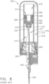
- In a conventional FUSION® tool sold by Kyocera Senco, such as illustrated in
FIG. 8 , a workingcylinder portion 205 of the tool, has amovable piston subassembly 210. The tool has amain storage chamber 274, exhibiting an outerpressure vessel wall 278. Within the main storage chamber is a workingcylinder 271, and the working cylinder exhibits acylinder wall 270. Inside thecylinder wall 270 is amovable piston 280, and above the piston is agas pressure chamber 276, whereas below the piston is a venting chamber 275 (in this view ofFIG. 8 ). - The
piston 280 has aseal 286, and above the seal (in this view) is a firstslidable bearing 288, and below the seal (in this view) is a secondslidable bearing 289. Between the second slidable bearing 289 and theseal 286 is agrease reservoir 282. The grease reservoir provides lubrication for the tool. - At the lower end of the
piston 280 is an opening in which atop end portion 230 of adriver 290 is held in place by a connectingpin 232. Thedriver 290 exhibitsdriver teeth 292, and extends out of thecylinder base 296. Between the bottom of themain storage chamber 274, and the cylinder base, is astationary piston stop 284. - The current FUSION® tool utilizes a lubricant that during manufacture is deposited on the cylinder wall and on the piston seal. This lubricant is important to the operation of the tool. However, the lubricant cannot be resupplied without disassembling the tool.
- Another challenge is to construct the piston with a hard material that also slides along the cylinder wall. The current FUSION® tool, as depicted in
FIG. 8 , illustrates the piston as a solid piece of material typically made of metal. Pistonslidable bearings
The documentFR1355560 A FR1355560 A - Accordingly, it is an advantage to include a small volume or recess in the outer perimeter of the piston of a power tool that retains a porous media, such as foam material, that holds and dispenses a liquid lubricant, which increases the life of the piston, cylinder, and the piston seals.
- It is another advantage to provide a lubricant used with a piston of a fastener driving tool, by storing the lubricant in open cell foam material in a recess of the piston outer surface, in which the foam holds and continuously deposits the lubricant along the piston and cylinder wall during the life of the tool. This provides improved wear characteristics that result in improved pressure retention over a longer tool life. The lubricant captured in the foam will tend to be constrained regardless of tool orientation.
- It is yet another advantage to provide a two-part piston that is mechanically attached to a driver assembly for a fastener driving tool. The upper material is non-metal and serves as guidance bearings against the cylinder wall that will not scratch the surface of the anodized cylinder.
- It is yet a further advantage to provide a piston with two separate portions of porous media, such as a foam material, for use in a fastener driving tool. At least the top foam portion stores and dispenses lubricant over the life of the tool. The lower foam portion acts as a debris "cleaner," removing debris that may enter the cylinder such as wood, gypsum, metallic particles, collation tape, sand, dirt, and moisture, or other items that are commonly found on construction jobsites. This debris build-up is due to the underside of the piston being exposed to ambient air.
- Additional advantages and other novel features will be set forth in part in the description that follows and in part will become apparent to those skilled in the art upon examination of the following or may be learned with the practice of the technology disclosed herein.
- To achieve the foregoing and other advantages, and in accordance with one aspect, a driver assembly according to
claim 1 is provided. - In accordance with another aspect, a driver assembly according to
claim 5 is provided. - Still other advantages will become apparent to those skilled in this art from the following description and drawings wherein there is described and shown a preferred embodiment in one of the best modes contemplated for carrying out the technology. As will be realized, the technology disclosed herein is capable of other different embodiments, and its several details are capable of modification in various, obvious aspects within the scope defined by the appended claims. Accordingly, the drawings and descriptions will be regarded as illustrative in nature and not as restrictive.
- The accompanying drawings incorporated in and forming a part of the specification illustrate several aspects of the technology disclosed herein, and together with the description and claims serve to explain the principles of the technology. In the drawings:
-
FIG. 1 is a side view of a piston subassembly for use in a fastener driving tool, as constructed according to the principles of the technology disclosed herein. -
FIG. 2 is a section view along the line 2-2 ofFIG. 1 . -
FIG. 3 is a perspective view showing the driver blade and driver teeth of the tool ofFIG. 1 . -
FIG. 4 is a section view of a working cylinder of the fastener driving tool ofFIG. 1 , showing the piston subassembly. -
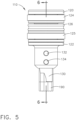
FIG. 5 is a side view of a second piston subassembly for use in a fastener driving tool, as constructed according to the principles of the technology disclosed herein. -
FIG. 6 is a section view along the line 6-6 ofFIG. 5 . -
FIG. 7 is a perspective view of the fastener driving tool ofFIG. 5 . -
FIG. 8 is a section view of a fastener driving tool known in the prior art. -
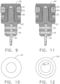
FIG. 9 is a section view similar to that ofFIG. 2 , in which a porous media, such as foam material, is arranged in stacks. -
FIG. 10 is a top elevational view of the foam material ofFIG. 9 . -
FIG. 11 is a section view similar to that ofFIG. 2 , in which a porous media, such as foam material, is layered, such that an outer layer covers or surrounds an inner layer. -
FIG. 12 is a top elevational view of the foam material ofFIG. 11 . - Reference will now be made in detail to the present preferred embodiment, an example of which is illustrated in the accompanying drawings, wherein like numerals indicate the same elements throughout the views.
- It is to be understood that the technology disclosed herein is not limited in its application to the details of construction and the arrangement of components set forth in the following description or illustrated in the drawings. The technology disclosed herein is capable of other embodiments and of being practiced or of being carried out in various ways within the scope defined by the appended claims. Also, it is to be understood that the phraseology and terminology used herein is for the purpose of description and should not be regarded as limiting. The use of "including," "comprising," or "having" and variations thereof herein is meant to encompass the items listed thereafter and equivalents thereof as well as additional items. Unless limited otherwise, the terms "connected," "coupled," and "mounted," and variations thereof herein are used broadly and encompass direct and indirect connections, couplings, and mountings. In addition, the terms "connected" and "coupled" and variations thereof are not restricted to physical or mechanical connections or couplings. Furthermore, the terms "communicating with" and "in communications with" refer to two different physical or virtual elements that somehow pass signals or information between each other, whether that transfer of signals or information is direct or whether there are additional physical or virtual elements therebetween that are also involved in that passing of signals or information. Moreover, the term "in communication with" can also refer to a mechanical, hydraulic, or pneumatic system in which one end (a "first end") of the "communication" may be the "cause" of a certain impetus to occur (such as a mechanical movement, or a hydraulic or pneumatic change of state) and the other end (a "second end") of the "communication" may receive the "effect" of that movement/change of state, whether there are intermediate components between the "first end" and the "second end," or not.
- The terms "first" and "second" preceding an element name, e.g., first inlet, second inlet, etc., are used for identification purposes to distinguish between similar or related elements, results or concepts, and are not intended to necessarily imply order, nor are the terms "first" and "second" intended to preclude the inclusion of additional similar or related elements, results or concepts, unless otherwise indicated.
- Referring now to
FIG. 1 , a piston subassembly for use in a fastener driving tool generally designated by thereference numeral 10 has two main halves: apiston top 20, and apiston bottom 22. Thepiston top 20 is constructed of a hard plastic, or other non-metallic material, preferably Delrin, whereas the piston bottom 22 is constructed of metal, preferably aluminum. The piston bottom is constructed with a stem that has a plurality ofmale threads 28, and the piston top has a threaded opening to receive the stem, in which the threads are female. The piston top is threadably attached using the piston bottom's male threads (seeFIG. 2 ), such that both piston parts move together as asingle piston subassembly 10. - It should be noted that the piston design described above is merely a preferred embodiment for constructing the overall piston, and other two-piece piston designs could be used without departing from the principles of this technology. For example, as one alternative design, the two
piston halves piston halves FIG. 4 ) will tend to keep thetop piston half 20 firmly pressed against thebottom piston half 22 under almost all circumstances of tool operation. - The general shape of
piston subassembly 10 includes a cylindrical outer surface which has a circular cross-section, as can be seen inFIG. 3 . The center of the circular cross-section is located along a longitudinal axis of the piston, in which that longitudinal axis can be seen at "L" onFIG. 2 . It will be understood that the exact shape of the outer perimeter of the piston, and the exact shape of the corresponding inner surface of the cylinder sleeve, do not necessarily have to be precisely circular. Instead, these surfaces could have other geometric shapes, so long as they are "mating shapes," and still fall within the principles of the technology disclosed herein. With regard to the disclosure presented herein, it will be assumed that the piston indeed has a circular cross-section, and therefore, the inner surface of the cylinder sleeve is also circular. - A driver 90 (see
FIG. 3 ) has anupper attachment portion 30 that is installed during manufacture into an opening in the pistonbottom half 22. The piston bottom 22 exhibits two throughopenings pins upper portion 30, to thepiston bottom 22. It will be understood that the various directional nomenclature provided above is with respect to the illustration ofFIG. 2 , and the first embodiment can be used in many other angular positions, without departing from the principles of this technology. The use of these two connectingpins piston subassembly 10 aligned with thedriver 90. - It will be further understood that this
piston subassembly 10 is designed to move in a reciprocating manner along a direction that will be referred to herein as a longitudinal axis. OnFIG. 2 , such a longitudinal axis is designated by the letter "L." The connecting pins 32 and 34 are placed in a perpendicular, transverse direction, which is indicated onFIG. 2 by the letter "T." - The
piston top portion 20 has two circumferential recesses or grooves located on the outside surface of the piston. The upper groove (or recess) holds an annular-shapedmaterial 24 that comprises a porous media such as foam, and the lower groove (or recess) holds anannular seal 26, which in this illustrated embodiment is a lobed seal. (Note that theannular seal 26 is also sometimes referred to herein as a "perimeter seal," since it runs around the outer perimeter of the piston.) Theporous media 24 holds a liquid lubricant material (such asMOBIL VACTRA 2™ oil, a premium ISO Viscosity Grade 68 slideway oil), and acts as a reservoir for the lubricant. The porous material can comprise various specific types of
materials, such as an open cell foam material, or a sponge-like foam material, or an air filter material that is resistant to oil. It is preferred that the foam material is soft, flexible, and nonabrasive. - An open cell foam material works well for the purposes described herein, and it will be understood that the terms "foam" or "foam material" as used hereinafter refer to all such types of porous media that are able to hold an appropriate liquid or grease lubricant material for use in these power tools. It will also be understood that, for the purposes of this disclosure, the phrase "circumferential recess" refers to a recess or "groove" in the outer surface of the piston, for example, regardless of the exact shape of the cross-section of that piston; in other words, the piston could have a circular or elliptical cross-section shape, or even a square or rectangular cross-section shape, yet the recess being referred herein would nevertheless be referred to as a "circumferential" recess, so that these recesses are better understood by the reader of this disclosure.
- The
porous media 24 may hold a variety of alternative liquid lubricant materials. The liquid lubricant material type used will alter the friction of thepiston 10 during a lift cycle. It would be desirable for this liquid lubricant to be a lightweight oil having a viscosity around ISO 68 (about SAE 20W). - It should be noted that the "liquid" lubricant used for this purpose may contain solid particles as a form of grease in solution with a liquid; or possibly the "liquid" lubricant used could mainly comprise an appropriate grease material (with or without solid particles) that, when in use, acts as a semi-liquid or semi-solid material to spread out along the piston's surfaces as the piston undergoes reciprocating movements.
- Preferably, the
foam material 24 comprises open cell foam, such as a reticulated urethane foam, having an average cell density of about 2.36-3.15 pores per millimeter (60-80 pores per inch). The foam material should be resistant to lubricating oils, and perhaps also to grease. Certain types of air filter material can be used for thefoam material 24, including pre-filters used for KOHLER® or BRIGGS & STRATTON® lawnmower engines. - The
foam 24 is in constant contact with the inner cylinder wall, slowly dispensing lubricant over the life of the tool. Theseal 26 is also in constant contact with the cylinder wall, and keeps the lubricant contained inside the cylinder; moreover, the seal retains the high gas pressure above the piston (in the variable displacement volume 76). The cylinder and the seal may be pre-coated with an anti-seize lubricant, such as PERMATEX 133A™. (The anti-seize is wiped on, like a grease.) The driver assembly according to the claimed invention has anti-seize grease pre-applied to the inner surface of the hollow cylinder. It is to be noted that thefoam 24 does not act as a seal per se, but is intended to store and dispense lubricant along the cylinder wall. Also, a second seal "above" thefoam 24 is not necessary, because any lubricant that moves "above" the seal will be re-used by subsequent piston movements. - It should also be noted that, once the tool has been fully assembled, the
foam 24 becomes the sole source of the liquid lubricant for the cylinder and piston. More specifically, the foam acts as an inhibiting factor that prevents the lubricant from being dispensed too quickly, thereby increasing the normal life of the entire tool. - Although the statement in the preceding paragraph is true for certain embodiments, alternative embodiments are envisioned where a grease material is used in conjunction with a liquid lubricant, and the grease is typically not directly applied to the foam material. Instead, the grease is applied to the inner surface of the cylinder sleeve (cylinder wall 70) before the piston is installed. The driver assembly according to the claimed invention has anti-seize grease pre-applied to the inner surface of the hollow cylinder.
- As discussed above, various types of lubricants may work well in this fastener driving tool working cylinder. The liquid lubricants are generally to be applied to the
foam 24, as discussed above. The grease lubricants are generally to be applied to theseal 26 and/or to the inner surface of thecylinder wall 70. The driver assembly according to the claimed invention has anti-seize grease pre-applied to the inner surface of the hollow cylinder. In an exemplary embodiment, both a grease material and a liquid material are simultaneously used. - If a grease material is to be used in the working
cylinder 71, then it would be applied to the inner surface of the cylinder before thepiston subassembly 10 is installed therein. The driver assembly according to the claimed invention has anti-seize grease pre-applied to the inner surface of the hollow cylinder. Furthermore, the grease can also be applied to theseal 26, as per the tool designer's choice. If grease is used at theseal 26, that grease can be applied into the recess where the seal goes either before or after theseal 26 is installed onto theupper piston 20. In general, it is preferred to install thefoam 24 into its recess in theupper piston 20 before any liquid lubricant is applied to thatfoam 24. (It is difficult to install a "wet" piece of foam into that groove or recess.) Finally, it is likely better if at least some of the grease is applied "beneath"
the seal 26-i.e., into the small space between the seal and the bottom surface of the groove. The more grease-and the more liquid lubricant-that can be "stored" in this working cylinder and piston combination, the longer that combination will properly operate. - Referring now to
FIG. 4 , thepiston subassembly 10 is shown integrated into a working cylinder portion of a driving tool, which is generally referred to by thereference numeral 5. Anouter wall 78 contains amain storage chamber 74, in which a workingcylinder 71 encloses thepiston subassembly 10. The working cylinder portion includes acylinder base 96 that fully encloses themain storage chamber 74. Agas pressure chamber 76 is contained inside the working cylinder, above thepiston top 20. Thegas chamber 76 contains a variable volume, or "displacement volume," of pressurized gas that is used to drive the piston during operation. Beneath the piston bottom 22 is a cylinder "venting chamber" 75, which vents to atmosphere. - During operation, the
piston subassembly 10 slides along a cylinder inner wall (or "sleeve") 70 of the workingcylinder 71. The bearing surfaces 52, 54, and 56 ofpiston top 20 contact thecylinder wall 70 during normal movement. The piston bottom 22 is slightly smaller in diameter and does not contact the cylinder wall. As the piston subassembly slides along the cylinder wall, the piston is stopped by astationary piston stop 84. - These bearing surfaces 52, 54, and 56 are quite different than previous designs using metal pistons with insert bearings. In previous designs, the insert bearings provided a slidable surface along the cylinder wall, which allowed the piston to not touch the cylinder wall at all. In this new design, the bearing surfaces 52, 54, and 56 of the
piston subassembly 10 actually touch and slide along the cylinder wall surface, and they act as low-friction guide bearing surfaces, as well. - The
driver 90 moves with thepiston subassembly 10 during operation. The driver exhibitsdriver teeth 92. The driver moves along adriver track 93 through aguide body 36. Theguide body 36 is mounted beneath thecylinder base 96. The guide body receives a fastener from a magazine (not shown), and guides the driver and the fastener to an exit portion of the tool, and into a workpiece. It will be understood that the various directional nomenclature provided above is with respect to the illustration ofFIG. 4 , and the first embodiment can be used in many other angular orientations, without departing from the principles of this technology. - Referring now to
FIG. 5 , a second piston subassembly for use in a fastener driving tool generally designated by thereference numeral 110 has two main halves: apiston top 120, and apiston bottom 122. Thepiston top 120 is constructed of a hard plastic, or other non-metallic material, preferably Delrin, whereas thepiston bottom 122 is constructed of metal, preferably aluminum. The piston bottom is constructed with a stem that has a plurality ofmale threads 128, and the piston top has a threaded opening to receive the stem, in which the threads are female. The piston top is threadably attached using the piston bottom's male threads (seeFIG. 6 ), such that both piston parts move together as a single piston subassembly. It should be noted that the twopiston halves - The general shape of
piston subassembly 110 includes a cylindrical outer surface which has a circular cross-section, as can be seen inFIG. 7 . The center of the circular cross-section is located along a longitudinal axis of the piston, in which that longitudinal axis can be seen at "L" onFIG. 6 . It will be understood that the exact shape of the outer perimeter of the piston, and the exact shape of the corresponding inner surface of the cylinder sleeve, do not necessarily have to be precisely circular. Instead, these surfaces could have other geometric shapes, so long as they are "mating shapes," and still fall within the principles of the technology disclosed herein. With regard to the disclosure presented herein, it will be assumed that the piston indeed has a circular cross-section, and therefore, the inner surface of the cylinder sleeve is also circular. - A driver 190 (see
FIG. 6 ) has anupper attachment portion 130 that is installed during manufacture into an opening in the pistonbottom half 122. The piston bottom 122 exhibits two throughopenings pins upper portion 130, to thepiston bottom 122. It will be understood that the various directional nomenclature provided above is with respect to the illustration ofFIG. 5 , and the first embodiment can be used in many other angular positions, without departing from the principles of this technology. - It will be again understood that this
piston subassembly 110 is designed to move in a reciprocating manner along a direction that will be referred to herein as a longitudinal axis. OnFIG. 6 , such a longitudinal axis is designated by the letter "L." - The
piston top 120 has three circumferential recesses or grooves located on the outside surface of the piston. The upper groove holds a circular-shapedmaterial 124 that comprises a porous media, such as a foam material, and the lower groove holds another circular-shaped material of porous media (e.g., foam material) 125. The middle groove holds acircular seal 126. (Note that theannular seal 126 is also sometimes referred to herein as a "perimeter seal," since it runs around the outer perimeter of the piston. Moreover, the porous media-or foam piece-124 is sometimes referred to herein as a "first porous media," and the porous media-or foam piece-125 is sometimes referred to herein as a "second porous media.") In one embodiment, bothfoam pieces foam foam inner cylinder wall 71, slowly dispensing lubricant over the life of the tool. - The
seal 126 is also in constant contact with the cylinder, and keeps the lubricant contained inside the cylinder. It is to be noted that thefoam pieces foam 124 is not necessary, because any lubricant that moves "above" the seal will be re-used. Thelower foam piece 125, in addition to dispensing lubricant, also acts as a "wiper" or "catcher" for preventing outside debris from entering the seal's region of the tool in the area near the bottom of thecylinder 71. - In an alternate embodiment, the
foam 125 does not contain lubricant. Instead, the foam mainly acts as a "wiper" or "catcher" for debris that finds its way into the bottom area of the workingcylinder 71. If lubricant should happen to make its way past theseal 126 to thissecond foam piece 125, then thefoam piece 125 will re-distribute that lubricant. Optionally, thesecond foam piece 125 can receive a "light" amount of lubricant at the time of manufacture. - The
second foam material 125 in the embodiment ofFIG. 6 is positioned "below" theseal 126 for a reason. As discussed above, thefoam 125 acts as a "wiper" or "catcher" to keep outside debris from reaching theseal 126, thereby enhancing the life of theseal 126, and thereby extending the life of the tool by maintaining a high air pressure in the main storage chamber and in the spaces "above" the top of the piston (above the surface 120) for a longer time. - The
second foam material 125 in the embodiment ofFIG. 6 also acts as a "retainer" to keep the beneficial lubricant "above" thatfoam piece 125; i.e., it will tend to keep the lubricant where the piston travels inside the working cylinder. And, as such a "retainer," thefoam material 125 tends to keep the lubricant from traveling "down" (in this view) to the workpiece surface, when a fastener is driven. - It should be noted that the porous media (such as foam pieces) 24, 124, and 125 in the various embodiments disclosed herein do not need to be formed of a single piece of material. For example, the foam pieces could be arranged as a stack of foam pieces each having a smaller thickness, such as the
pieces FIG. 9 . The top annular shape of this stack of smaller thickness foam pieces would have the shape depicted onFIG. 10 . - Furthermore, the porous media (such as foam pieces) 24, 124, and 125 in the various embodiments could be layered as different inner and outer diameters, such as the
pieces FIG. 11 , in which theouter layer 64 covers theinner layer 62. The top annular appearance of the shapes of those layered foam pieces would have the form illustrated onFIG. 12 . In this configuration, the inner andouter foam pieces inner foam piece 62 could be selected for having an ability to maximize a large quantity of lubricant that can be retained, whereas theouter foam piece 64 could be selected for having a superior wicking ability, which would more readily transfer lubricant from its inner diameter to its outer diameter, and hence to the piston's outer perimeter surfaces near the cylinder inner wall. - It will be understood that the references to an inner diameter or an outer diameter of the hollow cylinder or of the piston, seal, or foam pieces can be referred to by other words, such as an inner (or outer) width, or an inner (or outer) dimension, while referring to the same or a similar portion of the parts that make up the power tool design disclosed herein. This is especially true if the piston and working cylinder are not perfectly round in shape. For example, the piston's outer shape (in cross-section) and the working cylinder's inner shape (in cross-section) could be elliptical, rather than circular, if desired.
- It will be further understood that the description of the
piston 10 inFIG. 4 , or thepiston 110 inFIG. 6 , for example, could be described as having "a top outer surface, a bottom outer surface, and a side wall outer surface that extends between the top and bottom outer surfaces," with reference to the characteristics of the combination of the upper piston portion 20 (inFIG. 4 ), the lower piston portion 22 (inFIG. 4 ), and theside walls FIG. 4 ), for example. Of course, the lower portion of thepiston 22 also has side walls, which are not numbered onFIG. 4 . - Finally, it will be additionally understood that the
piston subassembly - Note that some of the embodiments illustrated herein do not have all of their components included on some of the figures herein, for purposes of clarity. To see examples of such outer housings and other components, especially for earlier designs, the reader is directed to other U.S. patents and applications owned by Senco. Similarly, information about "how" the electronic controller operates to control the functions of the tool is found in other U.S. patents and applications owned by Senco. Moreover, other aspects of the present tool technology may have been present in earlier fastener driving tools sold by the Assignee, Kyocera Senco Industrial Tools, Inc., including information disclosed in previous U.S. patents and published applications. Examples of such publications are patent numbers
US 6,431,425 ;US 5,927,585 ;US 5,918,788 ;US 5,732,870 ;US 4,986,164 ;US 4,679,719 ;US 8,011,547 ,US 8,267,296 ,US 8,267,297 ,US 8,011,441 ,US 8,387,718 ,US 8,286,722 ,US 8,230,941 , andUS 8,763,874 ; also publishedU.S. patent application No. 2016/0288305 and publishedU.S. patent application, No. 2018/0178361 . - It will be further understood that any type of product described herein that has moving parts, or that performs functions (such as computers with processing circuits and memory circuits), should be considered a "machine," and not merely as some inanimate apparatus. Such "machine" devices should automatically include power tools, printers, electronic locks, and the like, as those example devices each have certain moving parts. Moreover, a computerized device that performs useful functions should also be considered a machine, and such terminology is often used to describe many such devices; for example, a solid-state telephone answering machine may have no moving parts, yet it is commonly called a "machine" because it performs well-known useful functions.
- As used herein, the term "proximal" can have a meaning of closely positioning one physical object with a second physical object, such that the two objects are perhaps adjacent to one another, although it is not necessarily required that there be no third object positioned therebetween. In the technology disclosed herein, there may be instances in which a "male locating structure" is to be positioned "proximal" to a "female locating structure." In general, this could mean that the two male and female structures are to be physically abutting one another, or this could mean that they are "mated" to one another by way of a particular size and shape that essentially keeps one structure oriented in a predetermined direction and at an X-Y (e.g., horizontal and vertical) position with respect to one another, regardless as to whether the two male and female structures actually touch one another along a continuous surface. Or, two structures of any size and shape (whether male, female, or otherwise in shape) may be located somewhat near one another, regardless if they physically abut one another or not; such a relationship could still be termed "proximal." Or, two or more possible locations for a particular point can be specified in relation to a precise attribute of a physical object, such as being "near" or "at" the end of a stick; all of those possible near/at locations could be deemed "proximal" to the end of that stick. Moreover, the term "proximal" can also have a meaning that relates strictly to a single object, in which the single object may have two ends, and the "distal end" is the end that is positioned somewhat farther away from a subject point (or area) of reference, and the "proximal end" is the other end, which would be positioned somewhat closer to that same subject point (or area) of reference.
- It will be understood that the various components that are described and/or illustrated herein can be fabricated in various ways, including in multiple parts or as a unitary part for each of these components, without departing from the principles of the technology disclosed herein. For example, a component that is included as a recited element of a claim hereinbelow may be fabricated as a unitary part; or that component may be fabricated as a combined structure of several individual parts that are assembled together. But that "multipart component" will still fall within the scope of the claimed, recited element for infringement purposes of claim interpretation, even if it appears that the claimed, recited element is described and illustrated herein only as a unitary structure.
- All documents cited in the Background and in the Detailed Description are not to be construed as an admission that it is prior art with respect to the technology disclosed herein.
- The foregoing description of a preferred embodiment has been presented for purposes of illustration and description. It is not intended to be exhaustive or to limit the technology disclosed herein to the precise form disclosed, and the technology disclosed herein may be further modified within the scope defined by the appended claims. Any examples described or illustrated herein are intended as non-limiting examples, and many modifications or variations of the examples, or of the preferred embodiment(s), are possible in light of the above teachings, without departing from the scope of the technology disclosed herein. The embodiment(s) was chosen and described in order to illustrate the principles of the technology disclosed herein and its practical application to thereby enable one of ordinary skill in the art to utilize the technology disclosed herein in various embodiments and with various modifications as are suited to particular uses contemplated. This application is therefore intended to cover any variations, uses, or adaptations of the technology disclosed herein using its general principles. Further, this application is intended to cover such departures from the present disclosure as come within known or customary practice in the art to which this technology disclosed herein pertains and which fall within the limits of the appended claims.
Claims (9)
- A driver assembly for use in a power tool, said driver assembly comprising:a movable piston (10, 110), exhibiting a top outer surface (20, 120), a bottom outer surface (22, 122), and a side wall outer surface extending between said top and bottom outer surfaces;a hollow cylinder (71) having an inner surface (70) surrounding said side wall outer surface of the piston;a movable driver (90) that is in mechanical communication with the piston;a guide body (36) configured to guide said driver and configured to receive a fastener to be driven by the driver toward an exit portion of said guide body;a first recess in said side wall outer surface of the piston; anda porous media (24, 124) positioned in said first recess along said side wall outer surface of the piston containing a liquid lubricant oil stored therein, wherein said porous media is configured to dispense said liquid lubricant oil onto said inner surface (70) of said hollow cylinder (71); andan anti-seize grease pre-applied to said inner surface (70) of said hollow cylinder (71);wherein: both said liquid lubricant oil and said anti-seize grease provide lubrication to at least a portion of said inner surface (70) of said hollow cylinder (71) proximal to said side wall outer surface of said piston (10, 110), as said piston moves through said hollow cylinder.
- The driver assembly of claim 1, further comprising:a second recess in said side wall outer surface of the piston located at a different position relative to said first recess along said side wall outer surface of the piston; anda perimeter seal (26, 126) positioned in said second recess.
- The driver assembly of claim 2,
wherein:said perimeter seal (26, 126) makes physical contact with said inner surface (70) of said hollow cylinder (71) as the piston (10, 110) moves through said cylinder in a reciprocating pattern; andsaid perimeter seal (26, 126) preventing a majority of said liquid lubricant oil from moving past said second recess in said side wall outer surface of the piston (10, 110), during an operating cycle of the piston's reciprocating motion. - The driver assembly of claim 3, further comprising:a main storage chamber (74) configured to contain a pressurized gas;wherein:
said cylinder (71) includes a variable displacement volume on a first side of the piston (10, 110) that is in pneumatic communication with said main storage chamber (74), and said cylinder (71) includes a variable venting volume on a second, opposite side of the piston (10, 110) that is in pneumatic communication with an outer environment. - A driver assembly for use in a power tool, said driver assembly comprising:A movable piston (10, 110), exhibiting a top outer surface (20, 120), a bottom outer surface (22, 122), and a side wall outer surface extending between said top and bottom outer surfaces;a hollow cylinder (71) having an inner surface (70) surrounding said side wall outer surface of the piston;a movable driver (90) that is in mechanical communication with the piston;a guide body (36) configured to guide said driver and configured to receive a fastener to be driven by the driver toward an exit portion of said guide body;a first recess in the side wall outer surface of the piston;a first porous media (24, 124) positioned in said first recess;a second recess in said side wall outer surface of the piston, located at a different position relative to said first recess along said side wall outer surface of the piston;a second porous media (125) positioned in said second recess;at least one of said first porous media (24, 124) and second porous media (125) containing a liquid lubricant oil stored therein, wherein said porous media is configured to dispense said liquid lubricant oil onto said inner surface (70) of said hollow cylinder (71); andan anti-seize grease pre-applied to said inner surface (70) of said hollow cylinder (71);wherein: both said liquid lubricant oil and said anti-seize grease provide lubrication to at least a portion of said inner surface (70) of said hollow cylinder (71) proximal to said side wall outer surface of said piston (10, 110), as said piston moves through said hollow cylinder.
- The driver assembly of claim 5, further comprising:a third recess in said side wall outer surface of the piston located at a different position along said side wall outer surface of the piston than said first and second recesses; anda perimeter seal (26, 126) positioned in said third recess.
- The driver assembly of claim 6,
wherein:said perimeter seal (26, 126) makes physical contact with said inner surface (70) of said hollow cylinder (71) as the piston (10, 110) moves through said cylinder (71) in a reciprocating pattern; andsaid perimeter seal (26, 126) preventing a majority of said liquid lubricant oil from moving past said third recess in said side outer wall surface, during an operating cycle of the piston's reciprocating motion. - The driver assembly of claim 7, further comprising:a main storage chamber (74) configured to contain a pressurized gas;wherein:said cylinder (71) includes a variable displacement volume on a first side of said piston (76) that is in pneumatic communication with said main storage chamber (74) of pressurized gas, and said cylinder (71) includes a variable venting volume on a second, opposite side of the piston (75) that is in pneumatic communication with an outer environment;
andsaid liquid lubricant oil is not prevented from moving toward said main storage chamber (74), where it will be re-used in later operational cycles. - The driver assembly of claim 8, wherein:said first recess and said first porous media (24, 124) are positioned proximal to said first side of the piston (20, 120);said second recess and said second porous media (125) are positioned proximal to said second side of the piston (22, 122); andsaid third recess and said perimeter seal (26, 126) are positioned between said first and second recesses along said outer surface of the piston.
Applications Claiming Priority (2)
| Application Number | Priority Date | Filing Date | Title |
|---|---|---|---|
| US201862746941P | 2018-10-17 | 2018-10-17 | |
| PCT/US2019/056422 WO2020081620A1 (en) | 2018-10-17 | 2019-10-16 | Working cylinder for power tool with piston lubricating system |
Publications (3)
| Publication Number | Publication Date |
|---|---|
| EP3867017A1 EP3867017A1 (en) | 2021-08-25 |
| EP3867017A4 EP3867017A4 (en) | 2022-07-20 |
| EP3867017B1 true EP3867017B1 (en) | 2025-04-09 |
Family
ID=70280370
Family Applications (1)
| Application Number | Title | Priority Date | Filing Date |
|---|---|---|---|
| EP19873438.6A Active EP3867017B1 (en) | 2018-10-17 | 2019-10-16 | Working cylinder for power tool with piston lubricating system |
Country Status (8)
| Country | Link |
|---|---|
| US (1) | US11413734B2 (en) |
| EP (1) | EP3867017B1 (en) |
| JP (1) | JP7162128B2 (en) |
| AU (2) | AU2019360114B2 (en) |
| CA (2) | CA3111568C (en) |
| FI (1) | FI3867017T3 (en) |
| NZ (1) | NZ773405A (en) |
| WO (1) | WO2020081620A1 (en) |
Families Citing this family (12)
| Publication number | Priority date | Publication date | Assignee | Title |
|---|---|---|---|---|
| US10843318B2 (en) * | 2015-04-30 | 2020-11-24 | Koki Holdings Co., Ltd. | Fastener driving machine |
| WO2021195188A1 (en) | 2020-03-25 | 2021-09-30 | Milwaukee Electric Tool Corporation | Powered fastener driver |
| US11712790B2 (en) * | 2020-04-14 | 2023-08-01 | Kyocera Senco Industrial Tools, Inc. | Pneumatic microfastener driving tool |
| AU2021267838B2 (en) | 2020-05-07 | 2024-03-21 | Kyocera Senco Industrial Tools, Inc. | Power driving tool with latch position sensor |
| US11819989B2 (en) * | 2020-07-07 | 2023-11-21 | Techtronic Cordless Gp | Powered fastener driver |
| WO2022209078A1 (en) * | 2021-03-31 | 2022-10-06 | 工機ホールディングス株式会社 | Work machine |
| CA3167425A1 (en) | 2021-07-16 | 2023-01-16 | Techtronic Cordless Gp | Powered fastener driver |
| WO2023080192A1 (en) * | 2021-11-08 | 2023-05-11 | 工機ホールディングス株式会社 | Work machine |
| EP4482651A1 (en) | 2022-02-21 | 2025-01-01 | Kyocera Senco Industrial Tools, Inc. | Magazine fastener guide for a fastener driving tool |
| JP2025025662A (en) * | 2023-08-10 | 2025-02-21 | 工機ホールディングス株式会社 | Work equipment |
| JP2025093093A (en) * | 2023-12-11 | 2025-06-23 | 株式会社マキタ | Driving tools |
| CN120027114B (en) * | 2025-04-21 | 2025-07-18 | 湖南协力液压有限公司 | Oil cylinder with self-lubricating system |
Family Cites Families (74)
| Publication number | Priority date | Publication date | Assignee | Title |
|---|---|---|---|---|
| US860536A (en) | 1906-11-24 | 1907-07-16 | Robert W Ellingham | Roller-pinion. |
| US1774967A (en) | 1929-08-03 | 1930-09-02 | James T Ellis | Piston for slush pumps |
| US2026409A (en) * | 1931-12-31 | 1935-12-31 | Harley T Wheeler | Packing ring |
| US2419192A (en) * | 1944-07-18 | 1947-04-22 | Oscar W Giese | Piston and cylinder construction |
| US2575455A (en) | 1945-12-12 | 1951-11-20 | Bocjl Corp | Impact tool |
| US2635932A (en) | 1949-03-28 | 1953-04-21 | Heusser Wilfrid | Piston ring assembly for the pistons of internal-combustion engines |
| GB755685A (en) * | 1953-07-20 | 1956-08-22 | Neville Rupert Anderson | Improvements in or relating to grease-lubricated air-operated piston and cylinder devices |
| US2814041A (en) | 1955-03-14 | 1957-11-26 | Emmett L Haley | Power devices |
| US2797971A (en) * | 1955-11-14 | 1957-07-02 | Cleveland Pneumatic Tool Co | Sectional fluid seal |
| US2933290A (en) | 1958-07-03 | 1960-04-19 | Jr Harold E Ryder | Rack shaft locking means |
| US3150488A (en) | 1961-11-22 | 1964-09-29 | Emmett L Haley | Power devices |
| FR1355560A (en) * | 1962-11-30 | 1964-03-20 | Strip of points, method of manufacture, and nailing apparatus using such points | |
| US3276417A (en) * | 1965-08-11 | 1966-10-04 | Louis C Flowers | Pressure indicating apparatus for a pneumatic tire |
| DE1510164A1 (en) | 1965-09-07 | 1970-02-26 | Drahtseilwerk Wurzen Veb | Device for preforming strands or wires for wire ropes |
| US3589588A (en) | 1969-07-14 | 1971-06-29 | George O Vasku | Impact tool |
| US3661216A (en) * | 1969-09-10 | 1972-05-09 | Nippon Pneumatic Mfg | Impact air driven tool |
| DE2026272C3 (en) * | 1970-05-29 | 1975-03-27 | Maschinenfabrik Augsburg-Nuernberg Ag, Zweigniederl. Nuernberg, 8500 Nuernberg | Pistons for internal combustion engines |
| JPS519199B2 (en) | 1972-04-03 | 1976-03-24 | ||
| US3847322A (en) | 1973-09-10 | 1974-11-12 | H Smith | Power driven hammer |
| US4005763A (en) * | 1975-03-19 | 1977-02-01 | Wallis Bernard J | Lubricating means for gas-operated cylinders |
| GB1559571A (en) | 1976-09-24 | 1980-01-23 | Avon Ind Polymers | Piston means for piston cylinder arrangements |
| US4215808A (en) | 1978-12-22 | 1980-08-05 | Sollberger Roger W | Portable electric fastener driving apparatus |
| IT8221968U1 (en) * | 1982-05-21 | 1983-11-21 | Frosi Grazia | Improved plunger, especially for gas transfer pumps |
| US4986164A (en) | 1983-06-13 | 1991-01-22 | Senco Products, Inc. | Pneumatic gun having improved firing valve |
| US4530455A (en) | 1983-08-11 | 1985-07-23 | Senco Products, Inc. | Piston and driver |
| US4557351A (en) * | 1984-07-25 | 1985-12-10 | Denice C. Reich Inc. | Lubrication system for a walking beam compressor |
| DE3527997A1 (en) * | 1985-08-03 | 1987-02-12 | Bauer Fritz & Soehne Ohg | GAS SPRING |
| US4679719A (en) | 1985-12-27 | 1987-07-14 | Senco Products, Inc. | Electronic control for a pneumatic fastener driving tool |
| US4741518A (en) | 1986-08-26 | 1988-05-03 | Wallis Bernard J | Self contained gas spring interchangeable with coil spring |
| DE8711784U1 (en) | 1987-08-31 | 1987-11-05 | Demba Metallwarenfabrik GmbH, 2072 Bargteheide | Electrically operated tacker |
| AU637367B2 (en) | 1990-04-24 | 1993-05-27 | Regitar Power Tools Co Ltd | A transmission mechanism for an electric stapling gun |
| DE4030869A1 (en) * | 1990-09-29 | 1992-04-02 | Suspa Compart Ag | FRICTION DAMPER |
| US5199627A (en) | 1991-03-29 | 1993-04-06 | Christensen Jeffrey M | Self powered magazine hammer |
| JP2568736Y2 (en) | 1993-12-06 | 1998-04-15 | マックス株式会社 | Portable electric staple driving machine |
| WO1996012591A1 (en) | 1994-10-21 | 1996-05-02 | Senco Products, Inc. | Pneumatic fastener driving tool and an electronic control system therefor |
| US5557905A (en) | 1995-01-31 | 1996-09-24 | Harding; Kay J. | Bit for administering animal medication |
| JP3676879B2 (en) | 1995-07-25 | 2005-07-27 | 株式会社マキタ | Fastener driving tool |
| JP3133005B2 (en) | 1996-12-25 | 2001-02-05 | 加茂精工株式会社 | Rotational and linear motion converter |
| US5927585A (en) | 1997-12-17 | 1999-07-27 | Senco Products, Inc. | Electric multiple impact fastener driving tool |
| US6568313B2 (en) * | 2001-03-07 | 2003-05-27 | Smc Kabushiki Kaisha | Fluid pressure cylinder apparatus |
| WO2003000946A1 (en) | 2001-06-26 | 2003-01-03 | Kabushiki Kaisha Toyota Chuo Kenkyusho | Sliding member and method for manufacture thereof |
| US6685193B2 (en) * | 2001-08-30 | 2004-02-03 | Illinois Tool Works Inc. | Self lubricating, non-sealing piston ring for an internal combustion fastener driving tool |
| DE10222338A1 (en) | 2002-05-21 | 2003-12-04 | Hilti Ag | Combustion-powered setting tool |
| WO2004011201A1 (en) | 2002-07-25 | 2004-02-05 | Yih Kai Enterprise Co.,Ltd. | A hand-held nailing tool |
| US6533156B1 (en) | 2002-09-09 | 2003-03-18 | We-Chou Chang | Pneumatic nail gun |
| DE10325920B4 (en) | 2003-06-07 | 2005-09-01 | Hilti Ag | Setting device driven by expandable gases |
| ATE394200T1 (en) | 2004-04-02 | 2008-05-15 | Black & Decker Inc | FASTENING TOOL WITH MODE SELECTION SWITCH |
| US20050279802A1 (en) * | 2004-06-14 | 2005-12-22 | Moeller Larry M | Seal for portable fastener driving tool |
| US7040521B2 (en) | 2004-09-01 | 2006-05-09 | Illinois Tool Works Inc. | Gas driven actuation feed tube for combustion powered fastener-driving tool |
| US20060180631A1 (en) | 2005-02-16 | 2006-08-17 | Chris Pedicini | Electric motor driven energy storage device for impacting |
| US7225962B2 (en) | 2005-02-18 | 2007-06-05 | Illinois Tool Works Inc. | Nail advancement systems for nail arrays disposed within nailing tool magazines |
| US7494037B2 (en) | 2005-05-12 | 2009-02-24 | Stanley Fastening Systems, L.P. | Fastener driving device |
| DE102005000107B4 (en) | 2005-08-25 | 2014-03-13 | Hilti Aktiengesellschaft | Pneumatically operated setting tool |
| US20070144753A1 (en) * | 2005-12-22 | 2007-06-28 | Microtorq, L.L.C. | Transducerized rotary tool |
| US7225961B1 (en) | 2006-05-11 | 2007-06-05 | Samson Power Tool Co., Ltd. | Air path arrangement for pneumatic nail gun |
| WO2007142997A2 (en) | 2006-05-31 | 2007-12-13 | Stanley Fastening Systems, L.P. | Fastener driving device |
| JP2008068356A (en) | 2006-09-14 | 2008-03-27 | Hitachi Koki Co Ltd | Electric driving machine |
| US8258086B2 (en) * | 2006-12-01 | 2012-09-04 | Henkel Corporation | Anti-seize composition with nano-sized lubricating solid particles |
| US20080190986A1 (en) | 2007-02-09 | 2008-08-14 | Chin-Hsiung Chang | Electric Nailing Mechanism |
| US8875969B2 (en) | 2007-02-09 | 2014-11-04 | Tricord Solutions, Inc. | Fastener driving apparatus |
| US8011547B2 (en) | 2007-10-05 | 2011-09-06 | Senco Brands, Inc. | Fastener driving tool using a gas spring |
| US8763874B2 (en) | 2007-10-05 | 2014-07-01 | Senco Brands, Inc. | Gas spring fastener driving tool with improved lifter and latch mechanisms |
| US8313545B2 (en) * | 2007-10-16 | 2012-11-20 | Illinois Tool Works Inc. | Air filter assembly for combustion tool |
| DE102008032791A1 (en) | 2008-07-11 | 2010-01-14 | Wacker Neuson Se | Drilling and / or hammer with relubrication device |
| JP5948216B2 (en) * | 2011-10-25 | 2016-07-06 | 株式会社Ihi | Piston ring manufacturing method |
| GB201216905D0 (en) * | 2012-09-21 | 2012-11-07 | Black & Decker Inc | A hammer drill |
| EP3000560A1 (en) | 2014-09-25 | 2016-03-30 | HILTI Aktiengesellschaft | Driving device with gas spring |
| US10518396B2 (en) * | 2014-12-23 | 2019-12-31 | Tti (Macao Commercial Offshore) Limited | Drive blade lubrication assembly and powered fastener driver containing the same |
| NZ735578A (en) | 2015-03-30 | 2019-03-29 | Senco Brands Inc | Lift mechanism for framing nailer |
| WO2017056810A1 (en) | 2015-09-30 | 2017-04-06 | 日立工機株式会社 | Driver |
| US20170080554A1 (en) | 2016-11-30 | 2017-03-23 | Caterpillar Inc. | Hydraulic hammer assembly |
| CN108779407A (en) * | 2016-12-19 | 2018-11-09 | 株式会社Vab | Lubricating oil additive, lubricating oil, lubricating grease composition, fuel oil additive, fuel oil and method of sludge inhibition |
| FI3558595T3 (en) | 2016-12-22 | 2023-12-14 | Kyocera Senco Industrial Tools Inc | FASTENER OPERATING TOOL WITH OPERATING DEVICE POSITION SENSORS |
| CA3072552A1 (en) * | 2017-08-09 | 2019-02-14 | Mainspring Energy, Inc. | Piston seal with solid lubricant applicator |
-
2019
- 2019-10-16 EP EP19873438.6A patent/EP3867017B1/en active Active
- 2019-10-16 AU AU2019360114A patent/AU2019360114B2/en active Active
- 2019-10-16 CA CA3111568A patent/CA3111568C/en active Active
- 2019-10-16 WO PCT/US2019/056422 patent/WO2020081620A1/en not_active Ceased
- 2019-10-16 CA CA3204017A patent/CA3204017A1/en active Pending
- 2019-10-16 US US16/654,315 patent/US11413734B2/en active Active
- 2019-10-16 FI FIEP19873438.6T patent/FI3867017T3/en active
- 2019-10-16 NZ NZ773405A patent/NZ773405A/en unknown
- 2019-10-16 JP JP2021514962A patent/JP7162128B2/en active Active
-
2022
- 2022-10-21 AU AU2022256196A patent/AU2022256196B2/en active Active
Also Published As
| Publication number | Publication date |
|---|---|
| JP2021535991A (en) | 2021-12-23 |
| EP3867017A1 (en) | 2021-08-25 |
| CA3111568C (en) | 2023-08-22 |
| JP7162128B2 (en) | 2022-10-27 |
| CA3111568A1 (en) | 2020-04-23 |
| AU2022256196A1 (en) | 2022-11-24 |
| CA3204017A1 (en) | 2020-04-23 |
| AU2019360114B2 (en) | 2022-08-11 |
| US20200122308A1 (en) | 2020-04-23 |
| NZ773405A (en) | 2023-07-28 |
| FI3867017T3 (en) | 2025-05-27 |
| AU2019360114A1 (en) | 2021-03-25 |
| AU2022256196B2 (en) | 2024-08-15 |
| EP3867017A4 (en) | 2022-07-20 |
| US11413734B2 (en) | 2022-08-16 |
| WO2020081620A1 (en) | 2020-04-23 |
Similar Documents
| Publication | Publication Date | Title |
|---|---|---|
| AU2022256196B2 (en) | Working cylinder for power tool with piston lubricating system | |
| US12194607B2 (en) | Working cylinder for power tool with piston lubricating system | |
| JP6938256B2 (en) | Driving tool | |
| US12194606B2 (en) | Working machine | |
| JP5621990B2 (en) | Sliding member | |
| EP2806178A1 (en) | Sliding member | |
| KR101402818B1 (en) | Electric hammer drill provided with circulation system of lubricant | |
| EP1270958A1 (en) | Hydraulic cylinder | |
| US6431053B1 (en) | Piston for a swashplate reciprocating compressor | |
| CN108328010B (en) | Ejector head for an ejector device of a sealing machine for sealing containers | |
| US5199345A (en) | Piston compressor for the oilfree compression of a gas | |
| CN101280753A (en) | Diesel engine oil jetting pump post rod parts | |
| JP4968274B2 (en) | Fuel supply pump | |
| JP2006275002A (en) | Piston for internal combustion engine | |
| JP3929952B2 (en) | Lubricator for guide device | |
| US20100054967A1 (en) | High-Pressure Fuel Pump | |
| JP5528688B2 (en) | Piston compressor | |
| CN215333980U (en) | Precision guide rail convenient to oiling | |
| JP3137503U (en) | Lubrication improved shape cams | |
| JP7780102B2 (en) | Work equipment | |
| CN201198802Y (en) | Post rod parts of diesel engine oil injecting pump | |
| JPH0663516U (en) | Chain with automatic lubricator | |
| KR20160053022A (en) | Cross Head Bearing having Lubricating Function on Dry Turning | |
| KR960008053A (en) | Hermetic compressor | |
| JP2007205233A (en) | Swash plate compressor |
Legal Events
| Date | Code | Title | Description |
|---|---|---|---|
| STAA | Information on the status of an ep patent application or granted ep patent |
Free format text: STATUS: THE INTERNATIONAL PUBLICATION HAS BEEN MADE |
|
| PUAI | Public reference made under article 153(3) epc to a published international application that has entered the european phase |
Free format text: ORIGINAL CODE: 0009012 |
|
| STAA | Information on the status of an ep patent application or granted ep patent |
Free format text: STATUS: REQUEST FOR EXAMINATION WAS MADE |
|
| 17P | Request for examination filed |
Effective date: 20210301 |
|
| AK | Designated contracting states |
Kind code of ref document: A1 Designated state(s): AL AT BE BG CH CY CZ DE DK EE ES FI FR GB GR HR HU IE IS IT LI LT LU LV MC MK MT NL NO PL PT RO RS SE SI SK SM TR |
|
| DAV | Request for validation of the european patent (deleted) | ||
| DAX | Request for extension of the european patent (deleted) | ||
| A4 | Supplementary search report drawn up and despatched |
Effective date: 20220617 |
|
| RIC1 | Information provided on ipc code assigned before grant |
Ipc: B25D 17/26 20060101ALI20220611BHEP Ipc: B25D 17/00 20060101ALI20220611BHEP Ipc: B25D 9/00 20060101ALI20220611BHEP Ipc: B25F 5/00 20060101ALI20220611BHEP Ipc: B25C 1/00 20060101AFI20220611BHEP |
|
| GRAP | Despatch of communication of intention to grant a patent |
Free format text: ORIGINAL CODE: EPIDOSNIGR1 |
|
| STAA | Information on the status of an ep patent application or granted ep patent |
Free format text: STATUS: GRANT OF PATENT IS INTENDED |
|
| INTG | Intention to grant announced |
Effective date: 20240612 |
|
| RIN1 | Information on inventor provided before grant (corrected) |
Inventor name: KABBES, ANTHONY D. Inventor name: MCCARDLE, THOMAS A. Inventor name: BRADLEY, DAVID D. |
|
| GRAJ | Information related to disapproval of communication of intention to grant by the applicant or resumption of examination proceedings by the epo deleted |
Free format text: ORIGINAL CODE: EPIDOSDIGR1 |
|
| STAA | Information on the status of an ep patent application or granted ep patent |
Free format text: STATUS: REQUEST FOR EXAMINATION WAS MADE |
|
| INTC | Intention to grant announced (deleted) | ||
| GRAP | Despatch of communication of intention to grant a patent |
Free format text: ORIGINAL CODE: EPIDOSNIGR1 |
|
| STAA | Information on the status of an ep patent application or granted ep patent |
Free format text: STATUS: GRANT OF PATENT IS INTENDED |
|
| INTG | Intention to grant announced |
Effective date: 20241128 |
|
| GRAS | Grant fee paid |
Free format text: ORIGINAL CODE: EPIDOSNIGR3 |
|
| GRAA | (expected) grant |
Free format text: ORIGINAL CODE: 0009210 |
|
| STAA | Information on the status of an ep patent application or granted ep patent |
Free format text: STATUS: THE PATENT HAS BEEN GRANTED |
|
| AK | Designated contracting states |
Kind code of ref document: B1 Designated state(s): AL AT BE BG CH CY CZ DE DK EE ES FI FR GB GR HR HU IE IS IT LI LT LU LV MC MK MT NL NO PL PT RO RS SE SI SK SM TR |
|
| REG | Reference to a national code |
Ref country code: GB Ref legal event code: FG4D |
|
| REG | Reference to a national code |
Ref country code: CH Ref legal event code: EP |
|
| REG | Reference to a national code |
Ref country code: DE Ref legal event code: R096 Ref document number: 602019068543 Country of ref document: DE |
|
| REG | Reference to a national code |
Ref country code: IE Ref legal event code: FG4D |
|
| REG | Reference to a national code |
Ref country code: FI Ref legal event code: FGE |
|
| REG | Reference to a national code |
Ref country code: SE Ref legal event code: TRGR |
|
| REG | Reference to a national code |
Ref country code: NL Ref legal event code: MP Effective date: 20250409 |
|
| PG25 | Lapsed in a contracting state [announced via postgrant information from national office to epo] |
Ref country code: NL Free format text: LAPSE BECAUSE OF FAILURE TO SUBMIT A TRANSLATION OF THE DESCRIPTION OR TO PAY THE FEE WITHIN THE PRESCRIBED TIME-LIMIT Effective date: 20250409 |
|
| REG | Reference to a national code |
Ref country code: AT Ref legal event code: MK05 Ref document number: 1783149 Country of ref document: AT Kind code of ref document: T Effective date: 20250409 |
|
| PG25 | Lapsed in a contracting state [announced via postgrant information from national office to epo] |
Ref country code: ES Free format text: LAPSE BECAUSE OF FAILURE TO SUBMIT A TRANSLATION OF THE DESCRIPTION OR TO PAY THE FEE WITHIN THE PRESCRIBED TIME-LIMIT Effective date: 20250409 Ref country code: PT Free format text: LAPSE BECAUSE OF FAILURE TO SUBMIT A TRANSLATION OF THE DESCRIPTION OR TO PAY THE FEE WITHIN THE PRESCRIBED TIME-LIMIT Effective date: 20250811 |
|
| REG | Reference to a national code |
Ref country code: LT Ref legal event code: MG9D |
|
| PG25 | Lapsed in a contracting state [announced via postgrant information from national office to epo] |
Ref country code: GR Free format text: LAPSE BECAUSE OF FAILURE TO SUBMIT A TRANSLATION OF THE DESCRIPTION OR TO PAY THE FEE WITHIN THE PRESCRIBED TIME-LIMIT Effective date: 20250710 Ref country code: NO Free format text: LAPSE BECAUSE OF FAILURE TO SUBMIT A TRANSLATION OF THE DESCRIPTION OR TO PAY THE FEE WITHIN THE PRESCRIBED TIME-LIMIT Effective date: 20250709 |
|
| PG25 | Lapsed in a contracting state [announced via postgrant information from national office to epo] |
Ref country code: PL Free format text: LAPSE BECAUSE OF FAILURE TO SUBMIT A TRANSLATION OF THE DESCRIPTION OR TO PAY THE FEE WITHIN THE PRESCRIBED TIME-LIMIT Effective date: 20250409 |
|
| PG25 | Lapsed in a contracting state [announced via postgrant information from national office to epo] |
Ref country code: BG Free format text: LAPSE BECAUSE OF FAILURE TO SUBMIT A TRANSLATION OF THE DESCRIPTION OR TO PAY THE FEE WITHIN THE PRESCRIBED TIME-LIMIT Effective date: 20250409 |
|
| PGFP | Annual fee paid to national office [announced via postgrant information from national office to epo] |
Ref country code: GB Payment date: 20250828 Year of fee payment: 7 |
|
| PG25 | Lapsed in a contracting state [announced via postgrant information from national office to epo] |
Ref country code: HR Free format text: LAPSE BECAUSE OF FAILURE TO SUBMIT A TRANSLATION OF THE DESCRIPTION OR TO PAY THE FEE WITHIN THE PRESCRIBED TIME-LIMIT Effective date: 20250409 |
|
| PG25 | Lapsed in a contracting state [announced via postgrant information from national office to epo] |
Ref country code: AT Free format text: LAPSE BECAUSE OF FAILURE TO SUBMIT A TRANSLATION OF THE DESCRIPTION OR TO PAY THE FEE WITHIN THE PRESCRIBED TIME-LIMIT Effective date: 20250409 |
|
| PGFP | Annual fee paid to national office [announced via postgrant information from national office to epo] |
Ref country code: FR Payment date: 20250908 Year of fee payment: 7 |
|
| PGFP | Annual fee paid to national office [announced via postgrant information from national office to epo] |
Ref country code: SE Payment date: 20250910 Year of fee payment: 7 |
|
| PG25 | Lapsed in a contracting state [announced via postgrant information from national office to epo] |
Ref country code: RS Free format text: LAPSE BECAUSE OF FAILURE TO SUBMIT A TRANSLATION OF THE DESCRIPTION OR TO PAY THE FEE WITHIN THE PRESCRIBED TIME-LIMIT Effective date: 20250709 |
|
| PG25 | Lapsed in a contracting state [announced via postgrant information from national office to epo] |
Ref country code: IS Free format text: LAPSE BECAUSE OF FAILURE TO SUBMIT A TRANSLATION OF THE DESCRIPTION OR TO PAY THE FEE WITHIN THE PRESCRIBED TIME-LIMIT Effective date: 20250809 |
|
| PG25 | Lapsed in a contracting state [announced via postgrant information from national office to epo] |
Ref country code: LV Free format text: LAPSE BECAUSE OF FAILURE TO SUBMIT A TRANSLATION OF THE DESCRIPTION OR TO PAY THE FEE WITHIN THE PRESCRIBED TIME-LIMIT Effective date: 20250409 |
|
| PGFP | Annual fee paid to national office [announced via postgrant information from national office to epo] |
Ref country code: DE Payment date: 20250902 Year of fee payment: 7 |
|
| REG | Reference to a national code |
Ref country code: DE Ref legal event code: R097 Ref document number: 602019068543 Country of ref document: DE |
|
| PG25 | Lapsed in a contracting state [announced via postgrant information from national office to epo] |
Ref country code: SM Free format text: LAPSE BECAUSE OF FAILURE TO SUBMIT A TRANSLATION OF THE DESCRIPTION OR TO PAY THE FEE WITHIN THE PRESCRIBED TIME-LIMIT Effective date: 20250409 Ref country code: DK Free format text: LAPSE BECAUSE OF FAILURE TO SUBMIT A TRANSLATION OF THE DESCRIPTION OR TO PAY THE FEE WITHIN THE PRESCRIBED TIME-LIMIT Effective date: 20250409 |
|
| PGFP | Annual fee paid to national office [announced via postgrant information from national office to epo] |
Ref country code: FI Payment date: 20251014 Year of fee payment: 7 |
|
| PG25 | Lapsed in a contracting state [announced via postgrant information from national office to epo] |
Ref country code: CZ Free format text: LAPSE BECAUSE OF FAILURE TO SUBMIT A TRANSLATION OF THE DESCRIPTION OR TO PAY THE FEE WITHIN THE PRESCRIBED TIME-LIMIT Effective date: 20250409 |
|
| PG25 | Lapsed in a contracting state [announced via postgrant information from national office to epo] |
Ref country code: EE Free format text: LAPSE BECAUSE OF FAILURE TO SUBMIT A TRANSLATION OF THE DESCRIPTION OR TO PAY THE FEE WITHIN THE PRESCRIBED TIME-LIMIT Effective date: 20250409 |
|
| PG25 | Lapsed in a contracting state [announced via postgrant information from national office to epo] |
Ref country code: RO Free format text: LAPSE BECAUSE OF FAILURE TO SUBMIT A TRANSLATION OF THE DESCRIPTION OR TO PAY THE FEE WITHIN THE PRESCRIBED TIME-LIMIT Effective date: 20250409 Ref country code: SK Free format text: LAPSE BECAUSE OF FAILURE TO SUBMIT A TRANSLATION OF THE DESCRIPTION OR TO PAY THE FEE WITHIN THE PRESCRIBED TIME-LIMIT Effective date: 20250409 |
|
| PG25 | Lapsed in a contracting state [announced via postgrant information from national office to epo] |
Ref country code: IT Free format text: LAPSE BECAUSE OF FAILURE TO SUBMIT A TRANSLATION OF THE DESCRIPTION OR TO PAY THE FEE WITHIN THE PRESCRIBED TIME-LIMIT Effective date: 20250409 |
|
| PLBE | No opposition filed within time limit |
Free format text: ORIGINAL CODE: 0009261 |
|
| STAA | Information on the status of an ep patent application or granted ep patent |
Free format text: STATUS: NO OPPOSITION FILED WITHIN TIME LIMIT |
|
| REG | Reference to a national code |
Ref country code: CH Ref legal event code: L10 Free format text: ST27 STATUS EVENT CODE: U-0-0-L10-L00 (AS PROVIDED BY THE NATIONAL OFFICE) Effective date: 20260218 |
|
| 26N | No opposition filed |
Effective date: 20260112 |