EP3865635A1 - Verbindungsvorrichtung, schiffsinnenwand und schiffsinnendecke - Google Patents
Verbindungsvorrichtung, schiffsinnenwand und schiffsinnendecke Download PDFInfo
- Publication number
- EP3865635A1 EP3865635A1 EP20157512.3A EP20157512A EP3865635A1 EP 3865635 A1 EP3865635 A1 EP 3865635A1 EP 20157512 A EP20157512 A EP 20157512A EP 3865635 A1 EP3865635 A1 EP 3865635A1
- Authority
- EP
- European Patent Office
- Prior art keywords
- ship
- holding unit
- plate element
- another
- further component
- Prior art date
- Legal status (The legal status is an assumption and is not a legal conclusion. Google has not performed a legal analysis and makes no representation as to the accuracy of the status listed.)
- Granted
Links
Images


Classifications
-
- E—FIXED CONSTRUCTIONS
- E04—BUILDING
- E04B—GENERAL BUILDING CONSTRUCTIONS; WALLS, e.g. PARTITIONS; ROOFS; FLOORS; CEILINGS; INSULATION OR OTHER PROTECTION OF BUILDINGS
- E04B1/00—Constructions in general; Structures which are not restricted either to walls, e.g. partitions, or floors or ceilings or roofs
- E04B1/38—Connections for building structures in general
- E04B1/61—Connections for building structures in general of slab-shaped building elements with each other
-
- E—FIXED CONSTRUCTIONS
- E04—BUILDING
- E04B—GENERAL BUILDING CONSTRUCTIONS; WALLS, e.g. PARTITIONS; ROOFS; FLOORS; CEILINGS; INSULATION OR OTHER PROTECTION OF BUILDINGS
- E04B1/00—Constructions in general; Structures which are not restricted either to walls, e.g. partitions, or floors or ceilings or roofs
- E04B1/38—Connections for building structures in general
- E04B1/61—Connections for building structures in general of slab-shaped building elements with each other
- E04B1/6108—Connections for building structures in general of slab-shaped building elements with each other the frontal surfaces of the slabs connected together
- E04B1/612—Connections for building structures in general of slab-shaped building elements with each other the frontal surfaces of the slabs connected together by means between frontal surfaces
- E04B1/6179—Connections for building structures in general of slab-shaped building elements with each other the frontal surfaces of the slabs connected together by means between frontal surfaces with protrusions and recesses on each frontal surface
-
- F—MECHANICAL ENGINEERING; LIGHTING; HEATING; WEAPONS; BLASTING
- F16—ENGINEERING ELEMENTS AND UNITS; GENERAL MEASURES FOR PRODUCING AND MAINTAINING EFFECTIVE FUNCTIONING OF MACHINES OR INSTALLATIONS; THERMAL INSULATION IN GENERAL
- F16B—DEVICES FOR FASTENING OR SECURING CONSTRUCTIONAL ELEMENTS OR MACHINE PARTS TOGETHER, e.g. NAILS, BOLTS, CIRCLIPS, CLAMPS, CLIPS OR WEDGES; JOINTS OR JOINTING
- F16B5/00—Joining sheets or plates, e.g. panels, to one another or to strips or bars parallel to them
- F16B5/0004—Joining sheets, plates or panels in abutting relationship
- F16B5/0008—Joining sheets, plates or panels in abutting relationship by moving the sheets, plates or panels substantially in their own plane, perpendicular to the abutting edge
-
- B—PERFORMING OPERATIONS; TRANSPORTING
- B63—SHIPS OR OTHER WATERBORNE VESSELS; RELATED EQUIPMENT
- B63B—SHIPS OR OTHER WATERBORNE VESSELS; EQUIPMENT FOR SHIPPING
- B63B29/00—Accommodation for crew or passengers not otherwise provided for
- B63B29/02—Cabins or other living spaces; Construction or arrangement thereof
- B63B2029/027—Removable walls, e.g. for temporarily erecting cabin spaces in ship hold, or for subdividing living areas into smaller units; Fittings for removable wall panels
-
- B—PERFORMING OPERATIONS; TRANSPORTING
- B63—SHIPS OR OTHER WATERBORNE VESSELS; RELATED EQUIPMENT
- B63B—SHIPS OR OTHER WATERBORNE VESSELS; EQUIPMENT FOR SHIPPING
- B63B3/00—Hulls characterised by their structure or component parts
- B63B3/14—Hull parts
- B63B3/68—Panellings; Linings, e.g. for insulating purposes
-
- B—PERFORMING OPERATIONS; TRANSPORTING
- B63—SHIPS OR OTHER WATERBORNE VESSELS; RELATED EQUIPMENT
- B63B—SHIPS OR OTHER WATERBORNE VESSELS; EQUIPMENT FOR SHIPPING
- B63B5/00—Hulls characterised by their construction of non-metallic material
- B63B5/02—Hulls characterised by their construction of non-metallic material made predominantly of wood
- B63B5/06—Decks; Shells
-
- F—MECHANICAL ENGINEERING; LIGHTING; HEATING; WEAPONS; BLASTING
- F16—ENGINEERING ELEMENTS AND UNITS; GENERAL MEASURES FOR PRODUCING AND MAINTAINING EFFECTIVE FUNCTIONING OF MACHINES OR INSTALLATIONS; THERMAL INSULATION IN GENERAL
- F16B—DEVICES FOR FASTENING OR SECURING CONSTRUCTIONAL ELEMENTS OR MACHINE PARTS TOGETHER, e.g. NAILS, BOLTS, CIRCLIPS, CLAMPS, CLIPS OR WEDGES; JOINTS OR JOINTING
- F16B2200/00—Constructional details of connections not covered for in other groups of this subclass
- F16B2200/83—Use of a magnetic material
Definitions
- the invention relates to a device for connecting a plate element, in particular a ship's inner wall or ship's inner ceiling, with a further component, in particular the ship's inner wall or ship's inner ceiling, comprising at least one mechanical connecting element that can be fastened to the plate element and at least one further mechanical connecting element that can be fastened to the further component, the Connecting elements are designed and can be arranged relative to one another in such a way that the connecting elements at least partially engage behind one another when the plate element is connected to the further component as intended.
- the invention also relates to a use of such a device.
- the invention relates to a ship's inner wall and a ship's inner ceiling, each having at least one plate element and at least one further component that can be connected to the plate element.
- a ship's inner wall or ship's inner ceiling of a ship's interior which can have a substructure for decorative cladding elements and which defines a net space on board a ship, is usually of modular construction so that it can be easily installed in a ship's interior when it is dismantled.
- a ship's inner wall or ship's inner ceiling of a ship's interior (hereinafter referred to as the ship's inner wall or ship's inner ceiling for the sake of simplicity) can be easily adapted to the respective spatial conditions of the ship's interior due to its modular structure, especially at the installation site.
- connections between a plate element and a further component of a ship's inner wall or a ship's inner ceiling can be released or reversed without being destroyed, since the plate element can then be easily removed from its mounted position, for example around a behind the plate element
- a plate element of a ship's inner wall or a ship's inner ceiling with a mechanical connecting element and to equip a further component of the ship's inner wall or ship's inner ceiling, for example a component of a substructure of the ship's inner wall or ship's inner ceiling, with a further mechanical connecting element, the connecting elements being designed in this way and can be arranged relative to one another so that the connecting elements engage behind one another when the plate element is connected to the further component as intended.
- the plate element can to a certain extent be suspended from the further component or carried by the latter via the mechanical connection which is established by the connecting elements reaching behind each other in some cases.
- a corresponding connecting element can also be referred to as a rebate strip or a sliding flap.
- a correspondingly manufactured mechanical connection between the plate element and the further component can also be referred to as a folding ledge coupling.
- ball catches to secure a plate element connected to another component against slipping and falling, the slipping being a result of the release of the rebate coupling due to vibrations during ship operation or improper handling during a construction phase.
- the ball catches have to be installed by fitters on board the ship or in advance during assembly in a workshop, since a very precise positioning of the ball catch is essential for their function. This exact positioning of the ball catch requires a high degree of precision and experience on the part of the fitters.
- One object of the invention is to provide a simple safeguard against loosening of a rebate coupling via which a plate element, in particular a ship's inner wall or ship's inner ceiling, is connected to a further component, in particular the ship's inner wall or ship's inner ceiling.
- a device according to the invention for connecting a plate element, in particular a ship's inner wall or ship's inner ceiling, with a further component, in particular the ship's inner wall or ship's inner ceiling, has at least one mechanical connecting element that can be fastened to the plate element and at least one further mechanical connecting element that can be fastened to the further component, the connecting elements are designed and can be arranged relative to one another in such a way that the connecting elements at least partially engage behind one another when the plate element is connected to the further component as intended.
- the device according to the invention has at least one connecting device by means of which the plate element can be connected to the further component in such a way that the connecting elements are coupled to one another with a force that is parallel to a connecting plane in which connecting sections of the at least partially mutually exclusive engaging behind connecting elements at least partially bear against each other, and acts against a release direction in which the connecting elements are detachable from each other.
- the plate element connected to the further component via the connecting elements is secured to the further component by means of the connecting device in at least partially mutually engaging connecting elements, namely against displacement of the plate element parallel to and in the release direction relative to the further component.
- the connecting elements are simultaneously secured to one another in the connecting position in which the connecting elements at least partially engage behind one another, to be precise also against a displacement of the connecting elements relative to one another in the release direction.
- This can reliably prevent the connecting elements from moving away from one another in the release direction due to vibrations during operation of a suitably equipped ship, which could in particular result in the rebate coupling formed by the at least partially mutual engagement of the connecting elements being released. This would detach the plate element from the further component, which is to be prevented.
- the invention thus provides a simple safeguard against loosening of the rebate strip coupling formed by the connecting elements.
- the rebate strip coupling can be released manually and without the use of tools, for example to carry out revision work, by moving the plate element in the release direction relative to the further component until the connecting elements no longer engage behind one another.
- the plate element can also be connected to the further component by means of the device according to the invention without the use of tools, in that the plate element is moved in the opposite direction to the release direction relative to the further component until the connecting elements at least partially engage behind one another and the connecting device is effective.
- the device according to the invention thus enables a significant reduction in the assembly effort required to produce a ship's inner wall or ship's inner ceiling.
- the device according to the invention can be used to initially equip a ship's interior or a ship's interior, or to retrofit a ship's interior.
- the device is preferably designed in such a way that it can be combined with conventional ship interior walls or ship interior ceilings or their constructions without structural changes or adaptations being necessary to the ship interior walls or ship interior ceilings.
- the device according to the invention is preferably standardized in such a way that the entire ship's inner wall or ship's inner ceiling, in particular across projects, can be used as flexibly and variably as possible, largely independent of dimensions and positions.
- the securing of such installation positions according to the invention has a significantly simplified structure. Since, according to the invention, such ball catches do not have to be laboriously assembled beforehand, a ship's inner wall or ship's inner ceiling can be produced significantly faster using the device according to the invention.
- a disadvantage of using ball catches compared to the present invention is in particular the greater need for space between the two elements to be connected to one another (plate element, further component), since ball catches have a greater installation depth. Therefore, up to now, individual components of a ball catch may have to be embedded in a plane of at least one of the elements to be connected to one another in order not to conflict with sliding tabs / rebate strip holders.
- the plate element can form the outer visible surface of a ship's interior wall or ship's interior ceiling.
- the mechanical connecting element can be attached to the plate element directly or via at least one further element.
- the further component can be a component of a substructure of a ship's inner wall or ship's inner ceiling.
- the further mechanical connecting element can be attached to the further component directly or indirectly via at least one further element.
- the further elements can be components of the device according to the invention or elements independent thereof.
- Each connecting element can have a fastening section via which the connecting element can be fastened to the plate element or the further component.
- each connecting element has a connecting section which, when the plate element is properly connected to the further component, partially or completely engages behind the connecting section of the further connecting element, the connecting sections being aligned parallel to one another and resting against one another in the connecting plane.
- the fastening section of the respective connecting element can be arranged offset to the connecting section of the connecting element, whereby the connecting element is, so to speak, S-shaped.
- the at least partially mutual engagement of the connecting elements can be limited by the connecting section of at least one connecting element striking a step or a step-shaped transition area between the fastening section and the connecting section of the further connecting element.
- At least one connecting element can be produced partially or completely from a plastic, a fiber-reinforced plastic, a metal or a metal alloy.
- the connecting device has at least one magnetic element that can be fastened to the plate element and at least one further magnetic element that can be fastened to the further component, the magnetic elements being designed and arranged relative to one another and to the connecting elements in such a way that the magnetic elements at least partially engage behind one another Connecting elements are arranged so close to one another or in contact with one another that a Magnetic attraction force is given, which is parallel to the connecting plane in which the connecting sections of the at least partially mutually engaging connecting elements at least partially abut each other, and acts against the release direction in which the connecting elements are detachable from each other.
- the plate element connected to the further component via the connecting elements is secured to the further component by means of the magnetic connecting device in the case of connecting elements that at least partially engage behind one another, namely against displacement of the plate element parallel to and in the release direction relative to the further component.
- the connecting elements are simultaneously secured to one another in the connecting position in which the connecting elements at least partially engage behind one another, to be precise also against a displacement of the connecting elements relative to one another in the release direction.
- This can reliably prevent the connecting elements from moving away from one another in the release direction due to vibrations during operation of a suitably equipped ship, which could in particular result in the rebate coupling formed by the at least partially mutual engagement of the connecting elements being released. This would detach the plate element from the further component, which is to be prevented.
- a simple safeguard against loosening of the rebate strip coupling formed by the connecting elements is provided.
- the magnetic element and / or the further magnetic element can be designed as a permanent magnet.
- the magnetic element and / or the further magnetic element can be produced, for example, using an alloy containing neodymium.
- the magnetic element can be attached to the plate element directly or indirectly via at least one further element.
- the further magnetic element can be attached to the further component directly or indirectly via at least one further element.
- the further elements can be components of the device according to the invention or elements independent thereof.
- the magnetic connection device can be set up to generate a magnetic force of attraction with a minimum value of 15N.
- the magnetic force of attraction acts parallel to or in the connecting plane in which the connecting sections of the connecting elements, which at least partially engage behind one another, are partially or completely in contact with one another.
- the magnetic force of attraction acts against the direction of release in which the connecting elements can be released from one another.
- the direction of release runs parallel to the connecting plane and is oriented perpendicular to the transition area that is just formed between the fastening section and the connecting section of the respective connecting element.
- the magnetic connecting device has at least one holding unit which can be fastened to the plate element and on which the magnetic element is fixed, and at least one further holding unit which can be fastened to the further component and to which the further magnetic element is fixed, the connecting element via the Holding unit can be connected to the plate element and the further connecting element via the further Holding unit can be connected to the further component.
- the connecting element can be fastened indirectly to the plate element via the holding unit and the further connecting element can be fastened indirectly to the further component via the further holding unit.
- the holding units are designed in the same way. This reduces the manufacturing costs of the device, since only a single shape of a holding unit in the form of identical parts has to be implemented.
- the device has at least one common mechanical connecting means, via which on the one hand the connecting element and the holding unit can be fastened to the plate element or on the other hand the further connecting element and the further holding unit can be fastened to the further component.
- a bore pattern of a connecting element can be transferred to the holding unit connected to it, so that bores of the connecting element can be arranged in alignment with bores of the holding unit connected to it, after which a section of the common mechanical connecting means can be passed through the bores that are aligned with one another in order to create the connecting element and to fasten the holding unit to the plate element or the further component.
- the holding unit and / or the further holding unit is at least partially made of a plastic, a fiber-reinforced plastic, a metal or a metal alloy.
- the selection of the material for the holding unit or further holding unit can be made taking into account mechanical and / or chemical influences on the holding unit in order to ensure maximum durability of the device.
- the holding unit and / or the further holding unit is a stamped component, a cast component or a 3D printed component.
- the holding unit or further holding unit can be produced in a simple manner and quickly in relatively large numbers.
- the punched component can be produced from a drawn aluminum profile by punching or laser cutting.
- the connecting device has at least one holding unit which can be fastened to the plate element and via which the connecting element can be connected to the cladding element, at least one further holding unit which can be fastened to the further component and via which the further connecting element can be connected to the further component, and at least a clamping spring with a U-shaped cross-section, each holding unit having at least one U-shaped holding section, the clamping spring being insertable partially captive into a receptacle of the holding section of the holding unit and partially captive into a receptacle of the holding section of the further holding unit.
- the plate element connected to the further component via the connecting elements is at least partially mutually engaging connecting elements secured by means of this mechanical connecting device on the further component, namely against displacement of the plate element parallel to and in the release direction relative to the further component.
- the connecting elements are simultaneously secured to one another in the connecting position in which the connecting elements at least partially engage behind one another, to be precise also against a displacement of the connecting elements relative to one another in the release direction.
- This can reliably prevent the connecting elements from moving away from each other in the release direction due to vibrations during operation of a suitably equipped ship, which could in particular result in the rebate coupling formed by the at least partially mutual engagement of the connecting elements being released. This would detach the plate element from the further component, which is to be prevented.
- a simple safeguard against loosening of the rebate strip coupling formed by the connecting elements is provided.
- the clamping spring can be made partially or completely from sheet metal.
- the clamping spring and the holding sections can be designed and structurally coordinated with one another in such a way that a snap connection or latching connection is implemented between the two holding sections via the clamping spring.
- the clamping spring can also be designed as a slide-in spring or slide-in clasp that can be pushed into the receptacles of the holding sections.
- the holding sections of the mechanical connecting device can be designed in accordance with the above-mentioned holding sections of the magnetic connecting device, so that the holding sections can optionally be connected to one another by means of a clamping spring or by means of magnetic elements.
- the mechanical connection device can be set up to generate a force with a minimum value of 15N. This force acts parallel to or in the connecting plane in which the connecting sections of the connecting elements, which at least partially engage behind one another, are partially or completely in contact with one another. In addition, the force acts against the direction of release in which the connecting elements can be released from one another.
- the clamping spring has two clamping legs connected to one another via a web, each holding section having two legs aligned parallel to one another, at the free ends of which an inwardly protruding projection is formed, the projections running towards one another and a distance from one another and wherein a bead extending transversely to a longitudinal extension of the clamping leg is formed on each clamping leg, in which two adjacent projections of the two holding sections engage.
- the projections thus snap into the respective bead in order to form a snap-in connection or snap connection.
- the clamping spring In its state inserted into the receptacles on the holding sections, the clamping spring can be elastically deformed by the contacts with the holding sections.
- the invention also enables the use of a device according to one of the above-mentioned configurations or a combination of at least two of these configurations with one another for connecting a plate element, in particular a ship's inner wall or a Ship interior ceiling, proposed with a further component, in particular the ship interior wall or ship interior ceiling.
- a plate element in particular a ship's inner wall or a Ship interior ceiling
- a further component in particular the ship interior wall or ship interior ceiling.
- a ship's inner wall according to the invention has at least one plate element, at least one further component that can be connected to the plate element and at least one device according to one of the above-mentioned configurations or a combination of at least two of these configurations, the plate element being connectable to the further component by means of the device.
- a ship's interior ceiling according to the invention has at least one plate element, at least one further component that can be connected to the plate element and at least one device according to one of the above configurations or a combination of at least two of these configurations with one another, the plate element being connectable to the further component by means of the device.
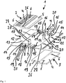
- Fig. 1 shows a schematic and perspective exploded view of an embodiment of a device 1 according to the invention for connecting a plate element (not shown), in particular a ship's inner wall (not shown) or Ship interior ceiling, with a further component (not shown), in particular the ship interior wall or ship interior ceiling.
- the device 1 has a mechanical connecting element 2 which can be fastened to the plate element and a further mechanical connecting element 3 which can be fastened to the further component.
- the connecting elements 2 and 3 are designed and can be arranged relative to one another in such a way that the connecting elements 2 and 3 partially engage behind one another when the plate element is properly connected to the further component.
- the connecting elements 2 and 3 are designed the same in the exemplary embodiment.
- Each connecting element 2 or 3 has a fastening section 4 and a connecting section 5 arranged in a stepwise offset from the fastening section 4, a straight transition area 26 being arranged between the fastening section 4 and the connecting section 5.
- Two through bores 6 are formed on the fastening section 4, via which the respective connecting element 2 or 3 can be fastened to the plate element or the further component.
- Each connecting element 2 or 3 is, so to speak, S-shaped.
- the device 1 has a magnetic connecting device 7 which has two magnetic elements 8 that can be fastened to the plate element and two further magnetic elements 9 that can be fastened to the further component.
- the magnetic elements 8 and 9 are designed and can be arranged relative to one another and to the connecting elements 2 and 3 such that the magnetic elements 8 and 9 are so close to one another in the case of connecting elements 2 and 3 that partially engage behind one another that a magnetic element 8 and 9 is placed between the magnetic elements 8 and 9 Attraction is given with a predetermined minimum value that is parallel to an in Fig. 3 Connection plane shown, in which connection sections 5 of the partially mutually engaging connecting elements 2 and 3 rest against one another, and against one in the Figs. 2 and 3 indicated release direction acts, in which the connecting elements 2 and 3 are detachable from each other.
- the magnetic connecting device 7 also has a holding unit 10 which can be fastened to the plate element and to which the magnetic elements 8 can be fastened, and a further holding unit 11 which can be fastened to the further component and to which the further magnetic elements 9 can be fastened.
- the connecting element 2 can be connected to the plate element via the holding unit 10 and the further connecting element 3 can be connected to the further component via the further holding unit 11.
- the holding units 10 and 11 are designed identically or as identical parts.
- the holding unit 10 and / or the further holding unit 11 is produced partially or completely from a plastic, a fiber-reinforced plastic, a metal or a metal alloy.
- the holding unit 10 and / or the further holding unit 11 is a cast component or a 3D printed component.
- Each holding unit 10 or 11 has a fastening section 12 via which the holding unit 10 or 11 can be fastened to the plate element or further component.
- Two through bores 13 are formed on the fastening section 12, via which the respective holding unit 10 or 11 can be fastened to the plate element or the further component.
- the through bores 13 of the holding unit 10 are aligned with the through bores 6 of the connecting element 2 and the through bores 13 of the holding unit 11 are aligned with the through bores 6 of the connecting element 3.
- Ribs 14 are arranged on the fastening section 12 of the respective holding unit 10 or 11, via which the holding unit 10 or 11 can be supported on the further component or the plate element, as shown in FIG Fig. 3 is shown.
- ribs 15 are also arranged on the fastening section 12, via which the holding unit 10 or 11 can be supported on the plate element or the further component, as shown in FIG Fig. 3 is shown.
- Each holding unit 10 or 11 also has two U-shaped holding sections 16 connected to the fastening section 12, in each of which a magnetic element 8 or 9 can be captively received, including the respective magnetic element 8 or 9 laterally in the respective holding section 16 can be inserted.
- each holding section 16 has two legs 17 which are aligned parallel to one another and at the free ends of which an inwardly protruding projection 18 is formed.
- the projections 18 of the respective holding section 16 run towards one another and are spaced apart from one another which is smaller than a given dimension of the respective magnetic element 8 or 9 in the corresponding direction.
- Each holding section 16 is connected to the respective fastening section 12 via a web 19.
- a recess 27 is formed on the holding unit 10 or 11, in which the connecting section 5 of the connecting element 2 or 3 connected to the holding unit 10 or 11 can be at least partially arranged, see above that the holding sections 16 are arranged on opposite sides of the connecting section 5.
- the device 1 also has two common mechanical connecting means 20 for each connecting element 2 or 3, via which the respective connecting element 2 or 3 and the respective holding unit 10 or 11 can be fastened to the plate element or the further component.
- the connecting means 20 are passed through the respective through bores 6 and 13 and fastened to the plate element or further component.
- FIG. 11 shows a schematic and perspective illustration of the FIG Fig. 1 Device 1 shown in a functional state in which the connecting elements 2 and 3 partially engage behind one another.
- the magnetic elements 8 and 9 are arranged so close to one another that the magnetic connecting device 7 generates a sufficient magnetic force of attraction to secure the shown relative position between the connecting elements 2 and 3.
- the connecting means 20 have been passed through the through bores 6 and 13.
- the release direction 25 is indicated, in which the connecting elements 2 and 3 can be released from one another.
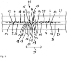
- Fig. 3 shows a schematic representation of an exemplary embodiment for a ship's inner wall 21 according to the invention.
- the ship's inner wall 21 has a plate element 22 and a further component 23 connected to the plate element 22.
- the ship's inner wall 21 has a device 1 corresponding to that in FIG Figs. 1 and 2 embodiment shown, the plate element 22 being connected to the further component 23 by means of the device 1.
- the description of the device 1 is referred to above in relation to the Figs. 1 and 2 referenced.
- Fig. 3 shows that the fastening section 12 of the holding unit 10 is supported via the ribs 14 on the further component 23 and via the ribs 15 on the cladding component 22 and that the fastening section 12 of the holding unit 11 is supported via the ribs 14 on the plate element 22 and via the ribs 15 is supported on the further component 23.
- the connecting plane 24 is shown, in which the connecting sections 5 of the connecting elements 2 and 3, which partially engage behind one another, rest against one another.
- Fig. 3 be a representation of a ship's interior ceiling.
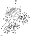
- Fig. 4 shows a schematic and perspective exploded view of details of a further embodiment of a device 28 according to the invention for connecting a plate element (not shown), in particular a ship's inner wall or ship's inner ceiling, not shown, to a further component (not shown), in particular the ship's inner wall or ship's inner ceiling.
- the device 28 also has a further holding unit (not shown) which can be fastened to the further component and via which the further connection element (not shown) can be connected to the further component.
- the further holding unit and the further connecting element are also corresponding to that shown in FIGS Figs. 1 to 3 embodiment shown. To avoid repetition, the above description is therefore also made in relation to the Figs. 1 to 3 referenced.
- Each connecting device 29 of the device 28 has a clamping spring 30 which is U-shaped in cross section.
- the holding unit 10 has two U-shaped holding sections 16, the respective clamping spring 30 being insertable partly captively into a receptacle 31 of the holding section 16 of the holding unit 10 and partially captively into a receptacle (not shown) of the holding section (not shown) of the further holding unit (not shown) .
- Each clamping spring 30 has two clamping legs 33 and 34 connected to one another via a web 32.
- a bead 35 is formed which extends transversely to a longitudinal extension of the respective clamping leg 33 or 34, in which two adjacent bead Projections 18 of the holding sections 16 of the two holding units 10 engage, as shown in FIG Fig. 5 is shown.
- Fig. 5 shows a schematic representation of a further exemplary embodiment of a ship's inner wall 36 according to the invention.
- the ship's inner wall 36 has a plate element 22 and a further component 23 connected to the plate element 22.
- the ship's inner wall 36 has a device 28 corresponding to that in FIG Fig. 4 embodiment shown, the plate element 22 being connected to the further component 23 by means of the device 28.
- Fig. 5 be a representation of a ship's interior ceiling.
- the further connecting element 3, the further holding unit 11 and the connecting means 20 of the device 28 are shown, which correspond to the in FIGS Figs. 1 to 3 are formed embodiment shown. To avoid repetition, refer to the description above regarding the Figs. 1 to 3 referenced.
- Fig. 5 shows a clamping spring 30 in its functional state in which two adjacent projections 18 of the holding sections 16 of the two holding units 10 and 11 engage in the beads 35 on the clamping legs 33 and 34 of the clamping spring 30.
Landscapes
- Engineering & Computer Science (AREA)
- Architecture (AREA)
- Physics & Mathematics (AREA)
- Electromagnetism (AREA)
- Civil Engineering (AREA)
- Structural Engineering (AREA)
- General Engineering & Computer Science (AREA)
- Mechanical Engineering (AREA)
- Connection Of Plates (AREA)
Abstract
Description
- Die Erfindung betrifft eine Vorrichtung zum Verbinden eines Plattenelements, insbesondere einer Schiffsinnenwand oder Schiffsinnendecke, mit einem weiteren Bauteil, insbesondere der Schiffsinnenwand oder Schiffsinnendecke, aufweisend wenigstens ein an dem Plattenelement befestigbares mechanisches Verbindungselement und wenigstens ein an dem weiteren Bauteil befestigbares weiteres mechanisches Verbindungselement, wobei die Verbindungselemente derart ausgebildet und relativ zueinander anordbar sind, dass sich die Verbindungselemente bei bestimmungsgemäß mit dem weiteren Bauteil verbundenem Plattenelement zumindest teilweise gegenseitig hintergreifen. Zudem betrifft die Erfindung eine Verwendung einer solchen Vorrichtung. Ferner betrifft die Erfindung eine Schiffsinnenwand und eine Schiffsinnendecke, jeweils aufweisend wenigstens ein Plattenelement und wenigstens ein mit dem Plattenelement verbindbares weiteres Bauteil.
- Eine Schiffsinnenwand oder Schiffsinnendecke eines Schiffsausbaus, der eine Unterkonstruktion für dekorative Verkleidungselemente aufweisen kann und eine Begrenzung eines Nettoraums an Bord eines Schiffs darstellt, ist üblicherweise modular aufgebaut, um im zerlegten Zustand auf einfache Art und Weise in einen Schiffsinnenraum eingebracht werden zu können. Zudem kann eine solche Schiffsinnenwand oder Schiffsinnendecke eines Schiffsausbaus (im Folgenden zur Vereinfachung Schiffsinnenwand bzw. Schiffsinnendecke genannt) aufgrund ihres modularen Aufbaus, insbesondere am Montageort, auf einfache Art und Weise an die jeweiligen räumlichen Gegebenheiten des Schiffsinnenraums angepasst werden.
- Von Vorteil ist, wenn Verbindungen zwischen einem Plattenelement und einem weiteren Bauteil einer Schiffsinnenwand oder einer Schiffsinnendecke zerstörungsfrei lösbar bzw. reversibel sind, da dann das Plattenelement auf einfache Art und Weise wieder aus seiner montierten Stellung entfernt werden kann, beispielsweise um einen hinter dem Plattenelement liegenden Bauraum, beispielsweise für Wartungs- und/oder Montagearbeiten, zugänglich zu machen oder eine technische Überprüfung bzw. Revision an der Schiffsinnenwand bzw. Schiffsinnendecke durchführen zu können.
- Hierzu ist es bekannt, ein Plattenelement einer Schiffsinnenwand oder einer Schiffsinnendecke mit einem mechanischen Verbindungselement auszustatten und ein weiteres Bauteil der Schiffsinnenwand bzw. Schiffsinnendecke, beispielsweise ein Bauteil einer Unterkonstruktion der Schiffsinnenwand bzw. Schiffsinnendecke, mit einem weiteren mechanischen Verbindungselement auszustatten, wobei die Verbindungselemente derart ausgebildet und relativ zueinander anordbar sind, dass sich die Verbindungselemente bei bestimmungsgemäß mit dem weiteren Bauteil verbundenem Plattenelement gegenseitig hintergreifen. Hierdurch kann das Plattenelement über die mechanische Verbindung, die durch das teilweise gegenseitige Hintergreifen der Verbindungselemente hergestellt wird, gewissermaßen an dem weiteren Bauteil aufgehängt bzw. von diesem getragen werden. Ein entsprechendes Verbindungselement kann auch als Falzleiste oder Schiebelasche bezeichnet werden. Dementsprechend kann eine entsprechend hergestellte mechanische Verbindung zwischen dem Plattenelement und dem weiteren Bauteil auch als Falzleistenkupplung bezeichnet werden.
- Des Weiteren ist es bekannt, ein entsprechend mit einem weiteren Bauteil verbundenes Plattenelement über Kugelschnäpper gegen ein Verrutschen und Herabfallen zu sichern, wobei das Verrutschen eine Folge des Lösens der Falzleistenkupplung aufgrund von Vibrationen während eines Schiffsbetriebs oder durch eine unsachgemäße Handhabung während einer Bauphase sein kann. Die Kugelschnäpper müssen durch Monteure an Bord des Schiffs oder vorab während eines Zusammenbaus in einer Werkstatt verbaut werden, da eine sehr genaue Positionierung der Kugelschnäpper wesentlich für deren Funktion ist. Diese exakte Positionierung der Kugelschnäpper erfordert ein hohes Maß an Präzision und Erfahrung der Monteure.
- Bei der Auslegung einer Schiffsinnenwand oder Schiffsinnendecke sollte darauf geachtet werden, dass möglichst einfache und platzsparende Konstruktionen verwendet werden, die ohne zusätzliche Elemente in verschiedenen Montageebenen auskommen. Um ein Designkonzept eines Schiffsinterieurs durch eine Revisionsmöglichkeit möglichst nicht zu beeinträchtigen, sollten Verbindungselemente möglichst unauffällig in eine Schiffsinnenwand oder Schiffsinnendecke integriert werden. Bisher mussten in der Regel verschiedene Unterkonstruktionselemente einer Schiffsinnenwand oder Schiffsinnendecke demontiert werden, um eine Zugänglichkeit überhaupt zu ermöglichen.
- Eine Aufgabe der Erfindung ist es, eine einfache Sicherung gegen ein Lösen einer Falzleistenkupplung, über die ein Plattenelement, insbesondere einer Schiffsinnenwand oder Schiffsinnendecke, mit einem weiteren Bauteil, insbesondere der Schiffsinnenwand oder Schiffsinnendecke, verbunden ist, bereitzustellen.
- Diese Aufgabe wird durch die unabhängigen Ansprüche gelöst. Vorteilhafte Ausgestaltungen sind in den abhängigen Ansprüchen, der nachfolgenden Beschreibung und den Figuren wiedergegeben, wobei diese Ausgestaltungen jeweils für sich genommen oder Kombination von wenigstens zwei dieser Ausgestaltungen miteinander einen vorteilhaften und/oder weiterbildenden Aspekt der Erfindung darstellen können.
- Eine erfindungsgemäße Vorrichtung zum Verbinden eines Plattenelements, insbesondere einer Schiffsinnenwand oder Schiffsinnendecke, mit einem weiteren Bauteil, insbesondere der Schiffsinnenwand oder Schiffsinnendecke, weist wenigstens ein an dem Plattenelement befestigbares mechanisches Verbindungselement und wenigstens ein an dem weiteren Bauteil befestigbares weiteres mechanisches Verbindungselement auf, wobei die Verbindungselemente derart ausgebildet und relativ zueinander anordbar sind, dass sich die Verbindungselemente bei bestimmungsgemäß mit dem weiteren Bauteil verbundenem Plattenelement zumindest teilweise gegenseitig hintergreifen. Zudem weist die erfindungsgemäße Vorrichtung wenigstens eine Verbindungseinrichtung auf, mittels der das Plattenelement derart mit dem weiteren Bauteil verbindbar ist, dass die Verbindungselemente mit einer Kraft aneinander gekoppelt sind, die parallel zu einer Verbindungsebene, in der Verbindungsabschnitte der sich zumindest teilweise gegenseitig hintergreifenden Verbindungselemente zumindest teilweise aneinander anliegen, und entgegen einer Löserichtung wirkt, in der die Verbindungselemente voneinander lösbar sind.
- Erfindungsgemäß wird das über die Verbindungselemente mit dem weiteren Bauteil verbundene Plattenelement bei sich zumindest teilweise gegenseitig hintergreifenden Verbindungselementen mittels der Verbindungseinrichtung an dem weiteren Bauteil gesichert, und zwar gegen eine Verlagerung des Plattenelements parallel zu und in der Löserichtung relativ zu dem weiteren Bauteil. Hierdurch werden gleichzeitig die Verbindungselemente in der Verbindungsstellung aneinander gesichert, in der sich die Verbindungselemente zumindest teilweise gegenseitig hintergreifen, und zwar ebenfalls gegen eine Verlagerung der Verbindungselemente relativ zueinander in der Löserichtung. Dadurch kann zuverlässig verhindert werden, dass sich die Verbindungselemente aufgrund von Vibrationen während eines Betriebs eines entsprechend ausgestatteten Schiffs in Löserichtung voneinander wegbewegen, was insbesondere zur Folge haben könnte, dass die durch das zumindest teilweise gegenseitige Hintergreifen der Verbindungselemente gebildete Falzleistenkupplung gelöst wird. Dadurch würde sich das Plattenelement von dem weiteren Bauteil lösen, was es zu verhindern gilt. Mit der Erfindung wird also eine einfache Sicherung gegen ein Lösen der durch die Verbindungselemente gebildeten Falzleistenkupplung bereitgestellt.
- Zudem kann die Falzleistenkupplung, beispielsweise zur Durchführung von Revisionsarbeiten, manuell und ohne den Einsatz von Werkzeug gelöst werden, indem das Plattenelement in Löserichtung relativ zu dem weiteren Bauteil bewegt wird, bis sich die Verbindungselemente nicht mehr gegenseitig hintergreifen. Ebenso kann das Verbinden des Plattenelements mit dem weiteren Bauteil mittels der erfindungsgemäßen Vorrichtung ohne den Einsatz von Werkzeug erfolgen, indem das Plattenelement entgegen der Löserichtung relativ zu dem weiteren Bauteil bewegt wird, bis sich die Verbindungselemente zumindest teilweise gegenseitig hintergreifen und die Verbindungseinrichtung wirksam ist. Die erfindungsgemäße Vorrichtung ermöglicht somit eine deutliche Reduzierung eines zur Herstellung einer Schiffsinnenwand oder Schiffsinnendecke erforderlichen Montageaufwands.
- Die erfindungsgemäße Vorrichtung kann zur Erstausstattung eines Schiffsinterieurs bzw. Schiffsausbaus oder zur Nachrüstung eines Schiffsinterieurs verwendet werden. In letzterem Fall ist die Vorrichtung vorzugsweise derart ausgebildet, dass sie mit herkömmlichen Schiffsinnenwänden oder Schiffsinnendecken bzw. deren Konstruktionen kombiniert werden kann, ohne dass an den Schiffsinnenwänden bzw. Schiffsinnendecken bauliche Veränderungen oder Anpassungen erforderlich sind.
- Da eine Einbausituation innerhalb eines Schiffsprojekts teilweise variieren kann, ist die erfindungsgemäße Vorrichtung vorzugsweise derart standardisiert, dass die gesamte die Vorrichtung aufweisende Schiffsinnenwand oder Schiffsinnendecke, insbesondere projektübergreifend, möglichst flexibel und variabel weitgehend unabhängig von Maßen und Positionen eingesetzt werden kann.
- Gegenüber der eingangs beschriebenen Verwendung von Kugelschnäppern zur Sicherung einer Einbaustellung eines Plattenelements weist die erfindungsgemäße Sicherung solcher Einbaustellungen einen deutlich vereinfachten Aufbau auf. Da gemäß der Erfindung solche Kugelschnäpper nicht aufwendig vorab montiert werden müssen, lässt sich eine Schiffsinnenwand oder Schiffsinnendecke unter Verwendung der erfindungsgemäßen Vorrichtung deutlich schneller herstellen. Ein Nachteil der Verwendung von Kugelschnäppern gegenüber der vorliegenden Erfindung liegt insbesondere im höheren Bedarf an Zwischenraum zwischen den beiden miteinander zu verbindenden Elementen (Plattenelement, weiteres Bauteil), da Kugelschnäpper eine höhere Einbautiefe haben. Daher müssen bisher gegebenenfalls einzelne Komponenten eines Kugelschnäppers in eine Ebene mindestens eines der miteinander zu verbindenden Elemente eingelassen werden, um keinen Konflikt mit Schiebelaschen/Falzleistenhalterungen zu bekommen.
- Das Plattenelement kann die äußere sichtbare Oberfläche einer Schiffsinnenwand oder Schiffsinnendecke bilden. Das mechanische Verbindungselement kann unmittelbar oder über wenigstens ein weiteres Element an dem Plattenelement befestigt werden. Das weitere Bauteil kann ein Bauteil einer Unterkonstruktion einer Schiffsinnenwand oder Schiffsinnendecke sein. Das weitere mechanische Verbindungselement kann unmittelbar oder über wenigstens ein weiteres Element mittelbar an dem weiteren Bauteil befestigt werden. Die weiteren Elemente können Bestandteile der erfindungsgemäßen Vorrichtung oder davon unabhängige Elemente sein.
- Jedes Verbindungselement kann einen Befestigungsabschnitt aufweisen, über den das Verbindungselement an dem Plattenelement bzw. dem weiteren Bauteil befestigbar ist. Zudem weist jedes Verbindungselement einen Verbindungsabschnitt auf, der bei bestimmungsgemäß mit dem weiteren Bauteil verbundenem Plattenelement teilweise oder vollständig hinter den Verbindungsabschnitt des weiteren Verbindungselements greift, wobei die Verbindungsabschnitte hierbei parallel zueinander ausgerichtet sind und in der Verbindungsebene aneinander anliegen. Der Befestigungsabschnitt des jeweiligen Verbindungselements kann versetzt zu dem Verbindungsabschnitt des Verbindungselements angeordnet sein, wodurch das Verbindungselement gewissermaßen S-förmig ausgebildet ist. Hierdurch kann beispielsweise das zumindest teilweise gegenseitige Hintergreifen der Verbindungselemente begrenzt werden, indem der Verbindungsabschnitt von wenigstens einem Verbindungselement an einer Stufe bzw. einem stufenförmigen Übergangsbereich zwischen dem Befestigungsabschnitt und dem Verbindungsabschnitt des weiteren Verbindungselements anschlägt. Wenigstens ein Verbindungselement kann teilweise oder vollständig aus einem Kunststoff, einem faserverstärkten Kunststoff, einem Metall oder einer Metalllegierung hergestellt sein.
- Gemäß einer vorteilhaften Ausgestaltung weist die Verbindungseinrichtung wenigstens ein an dem Plattenelement befestigbares Magnetelement und wenigstens ein an dem weiteren Bauteil befestigbares weiteres Magnetelement auf, wobei die Magnetelemente derart ausgebildet und relativ zueinander und zu den Verbindungselementen anordbar sind, dass die Magnetelemente bei sich zumindest teilweise gegenseitig hintergreifenden Verbindungselementen derart nahe beieinander oder in Kontakt miteinander angeordnet sind, dass zwischen den Magnetelementen eine magnetische Anziehungskraft gegeben ist, die parallel zu der Verbindungsebene, in der Verbindungsabschnitte der sich zumindest teilweise gegenseitig hintergreifenden Verbindungselemente zumindest teilweise aneinander anliegen, und entgegen der Löserichtung wirkt, in der die Verbindungselemente voneinander lösbar sind. Das über die Verbindungselemente mit dem weiteren Bauteil verbundene Plattenelement wird bei sich zumindest teilweise gegenseitig hintergreifenden Verbindungselementen mittels der magnetischen Verbindungseinrichtung an dem weiteren Bauteil gesichert, und zwar gegen eine Verlagerung des Plattenelements parallel zu und in der Löserichtung relativ zu dem weiteren Bauteil. Hierdurch werden gleichzeitig die Verbindungselemente in der Verbindungsstellung aneinander gesichert, in der sich die Verbindungselemente zumindest teilweise gegenseitig hintergreifen, und zwar ebenfalls gegen eine Verlagerung der Verbindungselemente relativ zueinander in der Löserichtung. Dadurch kann zuverlässig verhindert werden, dass sich die Verbindungselemente aufgrund von Vibrationen während eines Betriebs eines entsprechend ausgestatteten Schiffs in Löserichtung voneinander wegbewegen, was insbesondere zur Folge haben könnte, dass die durch das zumindest teilweise gegenseitige Hintergreifen der Verbindungselemente gebildete Falzleistenkupplung gelöst wird. Dadurch würde sich das Plattenelement von dem weiteren Bauteil lösen, was es zu verhindern gilt. Mit dieser vorteilhaften Ausgestaltung wird also eine einfache Sicherung gegen ein Lösen der durch die Verbindungselemente gebildeten Falzleistenkupplung bereitgestellt.
- Das Magnetelement und/oder das weitere Magnetelement kann als Dauermagnet ausgebildet sein. Das Magnetelement und/oder das weitere Magnetelement kann beispielsweise unter Verwendung einer Neodym aufweisenden Legierung hergestellt sein. Das Magnetelement kann unmittelbar oder über wenigstens ein weiteres Element mittelbar an dem Plattenelement befestigt werden. Das weitere Magnetelement kann unmittelbar oder über wenigstens ein weiteres Element mittelbar an dem weiteren Bauteil befestigt werden. Die weiteren Elemente können Bestandteile der erfindungsgemäßen Vorrichtung oder davon unabhängige Elemente sein.
- Die magnetische Verbindungeinrichtung kann eingerichtet sein, eine magnetische Anziehungskraft mit einem Mindestwert in Höhe von 15 N zu erzeugen. Die magnetische Anziehungskraft wirkt parallel zu oder in der Verbindungsebene, in der die Verbindungsabschnitte der sich zumindest teilweise gegenseitig hintergreifenden Verbindungselemente teilweise oder vollständig aneinander anliegen. Zudem wirkt die magnetische Anziehungskraft entgegen der Löserichtung, in der die Verbindungselemente voneinander lösbar sind. Die Löserichtung verläuft parallel zu der Verbindungsebene und ist senkrecht zu dem gerade ausgebildeten Übergangsbereich zwischen dem Befestigungsabschnitt und dem Verbindungsabschnitt des jeweiligen Verbindungselements ausgerichtet.
- Gemäß einer weiteren vorteilhaften Ausgestaltung weist die magnetische Verbindungseinrichtung wenigstens eine an dem Plattenelement befestigbare Halteeinheit, an der das Magnetelement festgelegt ist, und wenigstens eine an dem weiteren Bauteil befestigbare weitere Halteeinheit, an der das weitere Magnetelement festgelegt ist, auf, wobei das Verbindungselement über die Halteeinheit mit dem Plattenelement verbindbar ist und das weitere Verbindungselement über die weitere Halteeinheit mit dem weiteren Bauteil verbindbar ist. Hierbei ist das Verbindungselement über die Halteeinheit mittelbar an dem Plattenelement befestigbar und das weitere Verbindungselement über die weitere Halteeinheit mittelbar an dem weiteren Bauteil befestigbar.
- Gemäß einer weiteren vorteilhaften Ausgestaltung sind die Halteeinheiten gleich ausgebildet. Dies reduziert Herstellungskosten der Vorrichtung, da lediglich eine einzige Formgebung einer Halteeinheit in Form von Gleichteilen realisiert werden muss.
- Gemäß einer weiteren vorteilhaften Ausgestaltung weist die Vorrichtung wenigstens ein gemeinsames mechanisches Verbindungsmittel auf, über das einerseits das Verbindungselement und die Halteeinheit an dem Plattenelement oder andererseits das weitere Verbindungselement und die weitere Halteeinheit an dem weiteren Bauteil befestigbar sind. Hierdurch wird der Montageaufwand weiter reduziert. Hierzu kann beispielsweise ein Bohrungsbild eines Verbindungselements auf die damit verbundene Halteeinheit übertragen werden, sodass Bohrungen des Verbindungselements fluchtend zu Bohrungen der damit verbundenen Halteeinheit angeordnet werden können, wonach ein Abschnitt des gemeinsamen mechanischen Verbindungsmittels durch die jeweilig zueinander fluchtenden Bohrungen hindurchgeführt werden kann, um das Verbindungselement und die Halteeinheit an dem Plattenelement oder dem weiteren Bauteil zu befestigen. Durch diese Ausgestaltung ist kein nachträgliches Justieren erforderlich, was den Montageaufwand weiter reduziert.
- Gemäß einer weiteren vorteilhaften Ausgestaltung ist die Halteeinheit und/oder die weitere Halteeinheit zumindest teilweise aus einem Kunststoff, einem faserverstärkten Kunststoff, einem Metall oder einer Metalllegierung hergestellt. Die Auswahl des Werkstoffs für die Halteeinheit bzw. weitere Halteeinheit kann unter Berücksichtigung von mechanischen und/oder chemischen Einflüssen auf die Halteeinheit erfolgen, um eine maximale Dauerhaftigkeit der Vorrichtung sicherzustellen.
- Gemäß einer weiteren vorteilhaften Ausgestaltung ist die Halteeinheit und/oder die weitere Halteeinheit ein Stanzbauteil, ein Gussbauteil oder ein 3D-Druck-Bauteil. Hierdurch lassen sich die Halteeinheit bzw. weitere Halteeinheit auf einfache Art und Weise und schnell in relativ großer Stückzahl herstellen. Das Stanzbauteil kann durch Stanzen oder Laserschneiden aus einem gezogenen Aluminiumprofil hergestellt sein.
- Gemäß einer weiteren vorteilhaften Ausgestaltung weist die Verbindungseinrichtung wenigstens eine an dem Plattenelement befestigbare Halteeinheit, über die das Verbindungselement mit dem Verleidungselement verbindbar ist, wenigstens eine an dem weiteren Bauteil befestigbare weitere Halteeinheit, über die das weitere Verbindungselement mit dem weiteren Bauteil verbindbar ist, und wenigstens eine im Querschnitt U-förmig ausgebildete Klemmfeder auf, wobei jede Halteeinheit wenigstens einen U-förmig ausgebildeten Halteabschnitt aufweist, wobei die Klemmfeder teilweise unverlierbar in eine Aufnahme des Halteabschnitts der Halteeinheit und teilweise unverlierbar in eine Aufnahme des Halteabschnitts der weiteren Halteeinheit einfügbar ist. Das über die Verbindungselemente mit dem weiteren Bauteil verbundene Plattenelement wird bei sich zumindest teilweise gegenseitig hintergreifenden Verbindungselementen mittels dieser mechanischen Verbindungseinrichtung an dem weiteren Bauteil gesichert, und zwar gegen eine Verlagerung des Plattenelements parallel zu und in der Löserichtung relativ zu dem weiteren Bauteil. Hierdurch werden gleichzeitig die Verbindungselemente in der Verbindungsstellung aneinander gesichert, in der sich die Verbindungselemente zumindest teilweise gegenseitig hintergreifen, und zwar ebenfalls gegen eine Verlagerung der Verbindungselemente relativ zueinander in der Löserichtung. Dadurch kann zuverlässig verhindert werden, dass sich die Verbindungselemente aufgrund von Vibrationen während eines Betriebs eines entsprechend ausgestatteten Schiffs in Löserichtung voneinander wegbewegen, was insbesondere zur Folge haben könnte, dass die durch das zumindest teilweise gegenseitige Hintergreifen der Verbindungselemente gebildete Falzleistenkupplung gelöst wird. Dadurch würde sich das Plattenelement von dem weiteren Bauteil lösen, was es zu verhindern gilt. Mit dieser vorteilhaften Ausgestaltung wird also eine einfache Sicherung gegen ein Lösen der durch die Verbindungselemente gebildeten Falzleistenkupplung bereitgestellt.
- Die Klemmfeder kann teilweise oder vollständig aus einem Blech hergestellt sein. Die Klemmfeder und die Halteabschnitte können derart ausgebildet und baulich aufeinander abgestimmt sein, dass über die Klemmfeder eine Schnappverbindung oder Rastverbindung zwischen den beiden Halteabschnitten realisiert ist. Die Klemmfeder kann auch als in die Aufnahmen der Halteabschnitte einschiebbare Einschubfeder oder Einschubspange ausgebildet sein. Die Halteabschnitte der mechanischen Verbindungseinrichtung können entsprechend des oben genannten Halteabschnitten der magnetischen Verbindungseinrichtung ausgebildet sein, so dass die Halteabschnitte wahlweise mittels einer Klemmfeder oder mittels Magnetelementen miteinander verbunden werden können.
- Die mechanische Verbindungeinrichtung kann eingerichtet sein, eine Kraft mit einem Mindestwert in Höhe von 15 N zu erzeugen. Diese Kraft wirkt parallel zu oder in der Verbindungsebene, in der die Verbindungsabschnitte der sich zumindest teilweise gegenseitig hintergreifenden Verbindungselemente teilweise oder vollständig aneinander anliegen. Zudem wirkt die Kraft entgegen der Löserichtung, in der die Verbindungselemente voneinander lösbar sind.
- Gemäß einer weiteren vorteilhaften Ausgestaltung weist die Klemmfeder zwei über einen Steg miteinander verbundene Klemmschenkel auf, wobei jeder Halteabschnitt zwei parallel zueinander ausgerichtete Schenkel aufweist, an deren freien Enden jeweils ein nach innen ragender Vorsprung ausgebildet ist, wobei die Vorsprünge aufeinander zu verlaufen und einen Abstand voneinander aufweisen und wobei an jedem Klemmschenkel eine quer zu einer Längserstreckung des Klemmschenkels verlaufende Sicke ausgebildet ist, in die zwei aneinander anliegende Vorsprünge der beiden Halteabschnitte eingreifen. Die Vorsprünge rasten somit in die jeweilige Sicke ein, um eine Rastverbindung bzw. Schnappverbindung auszubilden. Die Klemmfeder kann in seinem in die Aufnahmen an den Halteabschnitten eingefügten Zustand durch die Kontakte mit den Halteabschnitten elastisch verformt sein.
- Mit der Erfindung wird zudem eine Verwendung einer Vorrichtung nach einer der oben genannten Ausgestaltungen oder einer Kombination von wenigstens zwei dieser Ausgestaltungen miteinander zum Verbinden eines Plattenelements, insbesondere einer Schiffsinnenwand oder einer Schiffsinnendecke, mit einem weiteren Bauteil, insbesondere der Schiffsinnenwand oder Schiffsinnendecke, vorgeschlagen. Mit der Verwendung sind die oben mit Bezug auf die Vorrichtung genannten Vorteile entsprechend verbunden.
- Eine erfindungsgemäße Schiffsinnenwand weist wenigstens ein Plattenelement, wenigstens ein mit dem Plattenelement verbindbares weiteres Bauteil und wenigstens eine Vorrichtung nach einer der oben genannten Ausgestaltungen oder einer Kombination von wenigstens zwei dieser Ausgestaltungen miteinander auf, wobei das Plattenelement mittels der Vorrichtung mit dem weiteren Bauteil verbindbar ist.
- Mit der Schiffsinnenwand sind die oben mit Bezug auf die Vorrichtung genannten Vorteile entsprechend verbunden.
- Eine erfindungsgemäße Schiffsinnendecke weist wenigstens ein Plattenelement, wenigstens ein mit dem Plattenelement verbindbares weiteres Bauteil und wenigstens eine Vorrichtung nach einer der oben genannten Ausgestaltungen oder einer Kombination von wenigstens zwei dieser Ausgestaltungen miteinander auf, wobei das Plattenelement mittels der Vorrichtung mit dem weiteren Bauteil verbindbar ist.
- Mit der Schiffsinnendecke sind die oben mit Bezug auf die Vorrichtung genannten Vorteile entsprechend verbunden.
- Im Folgenden wird die Erfindung unter Bezugnahme auf die beigefügten Figuren anhand bevorzugter Ausführungsformen beispielhaft erläutert, wobei die nachfolgend genannten Merkmale sowohl jeweils für sich genommen als auch in unterschiedlicher Kombination miteinander einen vorteilhaften und/oder weiterbildenden Aspekt der Erfindung darstellen können. Es zeigt:
-
Fig. 1 eine schematische und perspektivische Explosionsdarstellung eines Ausführungsbeispiels für eine erfindungsgemäße Vorrichtung; -
Fig. 2 eine schematische und perspektivische Darstellung der inFig. 1 gezeigten Vorrichtung in einem Funktionszustand; -
Fig. 3 eine schematische Darstellung eines Ausführungsbeispiels für eine erfindungsgemäße Schiffsinnenwand; -
Fig. 4 eine schematische und perspektivische Explosionsdarstellung von Details eines weiteren Ausführungsbeispiels für eine erfindungsgemäße Vorrichtung; und -
Fig. 5 eine schematische Darstellung eines weiteren Ausführungsbeispiels für eine erfindungsgemäße Schiffsinnenwand. - In den Figuren sind gleiche bzw. funktionsgleiche Bauteile mit denselben Bezugszeichen versehen. Eine wiederholte Beschreibung solcher Bauteile kann weggelassen sein.
-
Fig. 1 zeigt eine schematische und perspektivische Explosionsdarstellung eines Ausführungsbeispiels für eine erfindungsgemäße Vorrichtung 1 zum Verbinden eines nicht gezeigten Plattenelements, insbesondere einer nicht gezeigten Schiffsinnenwand oder Schiffsinnendecke, mit einem nicht gezeigten weiteren Bauteil, insbesondere der Schiffsinnenwand oder Schiffsinnendecke. - Die Vorrichtung 1 weist ein an dem Plattenelement befestigbares mechanisches Verbindungselement 2 und ein an dem weiteren Bauteil befestigbares weiteres mechanisches Verbindungselement 3 auf. Wie insbesondere die
Fign. 2 und3 zeigen, sind die Verbindungselemente 2 und 3 derart ausgebildet und relativ zueinander anordbar, dass sich die Verbindungselemente 2 und 3 bei bestimmungsgemäß mit dem weiteren Bauteil verbundenem Plattenelement teilweise gegenseitig hintergreifen. - Die Verbindungselemente 2 und 3 sind in dem Ausführungsbeispiel gleich ausgebildet. Jedes Verbindungselement 2 bzw. 3 weist einen Befestigungsabschnitt 4 und einen stufenförmig versetzt zu dem Befestigungsabschnitt 4 angeordneten Verbindungsabschnitt 5 auf, wobei zwischen dem Befestigungsabschnitt 4 und dem Verbindungsabschnitt 5 ein gerade verlaufender Übergangsbereich 26 angeordnet ist. An dem Befestigungsabschnitt 4 sind zwei Durchgangsbohrungen 6 ausgebildet, über die das jeweilige Verbindungselement 2 bzw. 3 an dem Plattenelement bzw. dem weiteren Bauteil befestigbar ist. Jedes Verbindungselement 2 bzw. 3 ist gewissermaßen S-förmig ausgebildet.
- Zudem weist die Vorrichtung 1 eine magnetische Verbindungseinrichtung 7 auf, die zwei an dem Plattenelement befestigbare Magnetelemente 8 und zwei an dem weiteren Bauteil befestigbare weitere Magnetelemente 9 aufweist. Die Magnetelemente 8 und 9 sind derart ausgebildet und relativ zueinander und zu den Verbindungselementen 2 und 3 anordbar, dass die Magnetelemente 8 und 9 bei sich teilweise gegenseitig hintergreifenden Verbindungselementen 2 und 3 derart nahe beieinander angeordnet sind, dass zwischen den Magnetelementen 8 und 9 eine magnetische Anziehungskraft mit einem vorgegebenen Mindestwert gegeben ist, die parallel zu einer in
Fig. 3 gezeigten Verbindungsebene, in der Verbindungsabschnitte 5 der sich teilweise gegenseitig hintergreifenden Verbindungselemente 2 und 3 aneinander anliegen, und entgegen einer in denFign. 2 und3 angedeuteten Löserichtung wirkt, in der die Verbindungselemente 2 und 3 voneinander lösbar sind. - Die magnetische Verbindungseinrichtung 7 weist zudem eine an dem Plattenelement befestigbare Halteeinheit 10, an der die Magnetelemente 8 festlegbar sind, und eine an dem weiteren Bauteil befestigbare weitere Halteeinheit 11, an der die weitere Magnetelemente 9 festlegbar sind, auf. Das Verbindungselement 2 ist über die Halteeinheit 10 mit dem Plattenelement verbindbar und das weitere Verbindungselement 3 ist über die weitere Halteeinheit 11 mit dem weiteren Bauteil verbindbar.
- In dem gezeigten Ausführungsbeispiel sind die Halteeinheiten 10 und 11 gleich bzw. als Gleichteile ausgebildet. Die Halteeinheit 10 und/oder die weitere Halteeinheit 11 ist teilweise oder vollständig aus einem Kunststoff, einem faserverstärkten Kunststoff, einem Metall oder einer Metalllegierung hergestellt. Die Halteeinheit 10 und/oder die weitere Halteeinheit 11 ist ein Gussbauteil oder ein 3D-Druck-Bauteil.
- Jede Halteeinheit 10 bzw. 11 weist einen Befestigungsabschnitt 12 auf, über den die Halteeinheit 10 bzw. 11 an dem Plattenelement bzw. weiteren Bauteil befestigbar ist. An dem Befestigungsabschnitt 12 sind zwei Durchgangsbohrungen 13 ausgebildet, über die die jeweilige Halteeinheit 10 bzw. 11 an dem Plattenelement bzw. dem weiteren Bauteil befestigbar ist. Die Durchgangsbohrungen 13 der Halteeinheit 10 sind fluchtend zu den Durchgangsbohrungen 6 des Verbindungselements 2 angeordnet und die Durchgangsbohrungen 13 der Halteeinheit 11 sind fluchtend zu den Durchgangsbohrungen 6 des Verbindungselements 3 angeordnet.
- An dem Befestigungsabschnitt 12 der jeweiligen Halteeinheit 10 bzw. 11 sind Rippen 14 angeordnet, über die sich die Halteeinheit 10 bzw. 11 an dem weiteren Bauteil bzw. dem Plattenelement abstützen kann, wie es in
Fig. 3 gezeigt ist. Auf einer gegenüberliegenden Seite sind an dem Befestigungsabschnitt 12 ebenfalls Rippen 15 angeordnet, über die sich die Halteeinheit 10 bzw. 11 an dem Plattenelement bzw. dem weiteren Bauteil abstützen kann, wie es inFig. 3 gezeigt ist. - Jede Halteeinheit 10 bzw. 11 weist zudem zwei mit dem Befestigungsabschnitt 12 verbundene, U-förmig ausgebildete Halteabschnitte 16 auf, in denen jeweils ein Magnetelement 8 bzw. 9 unverlierbar aufgenommen werden kann, wozu das jeweilige Magnetelement 8 bzw. 9 seitlich in den jeweiligen Halteabschnitt 16 eingeschoben werden kann. Um das jeweilige Magnetelement 8 bzw. 9 unverlierbar halten zu können, weist jeder Halteabschnitt 16 zwei parallel zueinander ausgerichtete Schenkel 17 auf, an deren freien Enden jeweils ein nach innen ragender Vorsprung 18 ausgebildet ist. Die Vorsprünge 18 des jeweiligen Halteabschnitts 16 verlaufen aufeinander zu und weisen einen Abstand voneinander auf, der kleiner als eine in entsprechender Richtung gegebene Dimension des jeweiligen Magnetelements 8 bzw. 9 ist. Jeder Halteabschnitt 16 ist über einen Steg 19 mit dem jeweiligen Befestigungsabschnitt 12 verbunden. Zwischen den Halteabschnitten 16 der jeweiligen Halteeinheit 10 bzw. 11 ist eine Aussparung 27 an der Halteeinheit 10 bzw. 11 ausgebildet, in der der Verbindungsabschnitt 5 des mit der Halteeinheit 10 bzw. 11 verbundenen Verbindungselements 2 bzw. 3 zumindest teilweise angeordnet werden kann, so dass die Halteabschnitte 16 auf einander gegenüberliegenden Seiten des Verbindungsabschnitts 5 angeordnet sind.
- Die Vorrichtung 1 weist ferner pro Verbindungselement 2 bzw. 3 zwei gemeinsame mechanische Verbindungsmittel 20 auf, über die das jeweilige Verbindungselement 2 bzw. 3 und die jeweilige Halteeinheit 10 bzw. 11 an dem Plattenelement bzw. dem weiteren Bauteil befestigbar sind. Hierzu werden die Verbindungsmittel 20 durch die jeweiligen Durchgangsbohrungen 6 und 13 hindurchgeführt und an dem Plattenelement bzw. weiteren Bauteil befestigt.
-
Fig. 2 zeigt eine schematische und perspektivische Darstellung der inFig. 1 gezeigten Vorrichtung 1 in einem Funktionszustand, in dem sich die Verbindungselemente 2 und 3 teilweise gegenseitig hintergreifen. Zudem sind die Magnetelemente 8 und 9 derart nahe beieinander angeordnet, dass die magnetische Verbindungseinrichtung 7 eine zur Sicherung der gezeigten Relativstellung zwischen den Verbindungselementen 2 und 3 ausreichende magnetische Anziehungskraft erzeugt. Des Weiteren sind die Verbindungsmittel 20 durch die Durchgangsbohrungen 6 und 13 hindurchgeführt worden. Ferner ist die Löserichtung 25 angedeutet, in der die Verbindungselemente 2 und 3 voneinander lösbar sind. -
Fig. 3 zeigt eine schematische Darstellung eines Ausführungsbeispiels für eine erfindungsgemäße Schiffsinnenwand 21. Die Schiffsinnenwand 21 weist ein Plattenelement 22 und ein mit dem Plattenelement 22 verbundenes weiteres Bauteil 23 auf. - Zudem weist die Schiffsinnenwand 21 eine Vorrichtung 1 entsprechend dem in den
Fign. 1 und2 gezeigten Ausführungsbeispiel auf, wobei das Plattenelement 22 mittels der Vorrichtung 1 mit dem weiteren Bauteil 23 verbunden ist. Zur Vermeidung von Wiederholungen wird bezüglich der Beschreibung der Vorrichtung 1 auf die obige Beschreibung zu denFign. 1 und2 verwiesen. -
Fig. 3 zeigt, dass der Befestigungsabschnitt 12 der Halteeinheit 10 über die Rippen 14 an dem weiteren Bauteil 23 und über die Rippen 15 an dem Verkleidungsbauteil 22 abgestützt ist und dass der Befestigungsabschnitt 12 der Halteeinheit 11 über die Rippen 14 an dem Plattenelement 22 und über die Rippen 15 an dem weiteren Bauteil 23 abgestützt ist. Zudem ist inFig. 3 die Verbindungsebene 24 gezeigt, in der Verbindungsabschnitte 5 der sich teilweise gegenseitig hintergreifenden Verbindungselemente 2 und 3 aneinander anliegen. Statt der Schiffsinnenwand 21 kannFig. 3 eine Darstellung einer Schiffsinnendecke sein. -
Fig. 4 zeigt eine schematische und perspektivische Explosionsdarstellung von Details eines weiteren Ausführungsbeispiels für eine erfindungsgemäße Vorrichtung 28 zum Verbinden eines nicht gezeigten Plattenelements, insbesondere einer nicht gezeigten Schiffsinnenwand oder Schiffsinnendecke, mit einem nicht gezeigten weiteren Bauteil, insbesondere der Schiffsinnenwand oder Schiffsinnendecke. - Von der Vorrichtung 28 sind lediglich ein Verbindungselement 2, eine Halteeinheit 10 und zwei Klemmfedern 30 gezeigt, wobei das Verbindungselement 2 und die Halteeinheit 10 entsprechend dem in den
Fign. 1 bis 3 gezeigten Ausführungsbeispiel ausgebildet sind. Zur Vermeidung von Wiederholungen wird diesbezüglich auf die obige Beschreibung zu denFign. 1 bis 3 verwiesen. Die Vorrichtung 28 weist zudem eine an dem weiteren Bauteil befestigbare, nicht gezeigte weitere Halteeinheit auf, über die das nicht gezeigte weitere Verbindungselement mit dem weiteren Bauteil verbindbar ist. Die weitere Halteeinheit und das weitere Verbindungselement sind ebenfalls entsprechend dem in denFign. 1 bis 3 gezeigten Ausführungsbeispiel ausgebildet. Zur Vermeidung von Wiederholungen wird daher auch diesbezüglich auf die obige Beschreibung zu denFign. 1 bis 3 verwiesen. - Jede Verbindungseinrichtung 29 der Vorrichtung 28 weist eine im Querschnitt U-förmig ausgebildete Klemmfedern 30 auf. Die Halteeinheit 10 weist zwei jeweils U-förmig ausgebildete Halteabschnitte 16 auf, wobei die jeweilige Klemmfeder 30 teilweise unverlierbar in eine Aufnahme 31 des Halteabschnitts 16 der Halteeinheit 10 und teilweise unverlierbar in eine nicht gezeigte Aufnahme des nicht gezeigten Halteabschnitts der nicht gezeigten weiteren Halteeinheit einfügbar ist.
- Jede Klemmfeder 30 weist zwei über einen Steg 32 miteinander verbundene Klemmschenkel 33 und 34 auf. An jedem Klemmschenkel 33 bzw. 34 ist eine quer zu einer Längserstreckung des jeweiligen Klemmschenkels 33 bzw. 34 verlaufende Sicke 35 ausgebildet, in die zwei aneinander anliegende Vorsprünge 18 der Halteabschnitte 16 der beiden Halteeinheiten 10 eingreifen, wie es in
Fig. 5 gezeigt ist. -
Fig. 5 zeigt eine schematische Darstellung eines weiteren Ausführungsbeispiels für eine erfindungsgemäße Schiffsinnenwand 36. Die Schiffsinnenwand 36 weist ein Plattenelement 22 und ein mit dem Plattenelement 22 verbundenes weiteres Bauteil 23 auf. - Zudem weist die Schiffsinnenwand 36 eine Vorrichtung 28 entsprechend dem in
Fig. 4 gezeigten Ausführungsbeispiel auf, wobei das Plattenelement 22 mittels der Vorrichtung 28 mit dem weiteren Bauteil 23 verbunden ist. Zur Vermeidung von Wiederholungen wird bezüglich der Beschreibung der Vorrichtung 1 auf die obige Beschreibung zuFig. 4 verwiesen. Statt der Schiffsinnenwand 36 kannFig. 5 eine Darstellung einer Schiffsinnendecke sein. Zudem sind das weitere Verbindungselement 3, die weitere Halteeinheit 11 und die Verbindungsmittel 20 der Vorrichtung 28 gezeigt, die entsprechend dem in denFign. 1 bis 3 gezeigten Ausführungsbeispiel ausgebildet sind. Zur Vermeidung von Wiederholungen wird diesbezüglich auf die obige Beschreibung zu denFign. 1 bis 3 verwiesen. -
Fig. 5 zeigt eine Klemmfeder 30 in ihrem Funktionszustand, in dem zwei aneinander anliegende Vorsprünge 18 der Halteabschnitte 16 der beiden Halteeinheiten 10 und 11 in die Sicken 35 an den Klemmschenkeln 33 und 34 der Klemmfeder 30 eingreifen. -
- 1
- Vorrichtung
- 2
- Verbindungselement
- 3
- Verbindungselement
- 4
- Befestigungsabschnitt von 2, 3
- 5
- Verbindungsabschnitt von 2, 3
- 6
- Durchgangsbohrung an 4
- 7
- Verbindungseinrichtung
- 8
- Magnetelement
- 9
- Magnetelement
- 10
- Halteeinheit
- 11
- Halteeinheit
- 12
- Befestigungsabschnitt von 10, 11
- 13
- Durchgangsbohrung an 12
- 14
- Rippe an 12
- 15
- Rippe an 12
- 16
- Halteabschnitt von 10, 11
- 17
- Schenkel von 16
- 18
- Vorsprung an 17
- 19
- Steg von 10, 11
- 20
- Verbindungsmittel
- 21
- Schiffsinnenwand
- 22
- Plattenelement
- 23
- weiteres Bauteil von 21
- 24
- Verbindungsebene
- 25
- Löserichtung
- 26
- Übergangsbereich zwischen 4 und 5
- 27
- Aussparung an 10, 11
- 28
- Vorrichtung
- 29
- Verbindungseinrichtung
- 30
- Klemmfeder
- 31
- Aufnahme an 16
- 32
- Steg von 30
- 33
- Klemmschenkel von 30
- 34
- Klemmschenkel von 30
- 35
- Sicke an 33, 34
- 36
- Schiffsinnenwand
Claims (12)
- Vorrichtung (1, 28) zum Verbinden eines Plattenelements (22), insbesondere einer Schiffsinnenwand (21, 36) oder Schiffsinnendecke, mit einem weiteren Bauteil (23), insbesondere der Schiffsinnenwand (21, 36) oder Schiffsinnendecke, aufweisend wenigstens ein an dem Plattenelement (22) befestigbares mechanisches Verbindungselement (2) und wenigstens ein an dem weiteren Bauteil (23) befestigbares weiteres mechanisches Verbindungselement (3), wobei die Verbindungselemente (2, 3) derart ausgebildet und relativ zueinander anordbar sind, dass sich die Verbindungselemente (2, 3) bei bestimmungsgemäß mit dem weiteren Bauteil (23) verbundenem Plattenelement (22) zumindest teilweise gegenseitig hintergreifen, gekennzeichnet durch wenigstens eine Verbindungseinrichtung (7, 29), mittels der das Plattenelement (22) derart mit dem weiteren Bauteil (23) verbindbar ist, dass die Verbindungselemente (2, 3) mit einer Kraft aneinander gekoppelt sind, die parallel zu einer Verbindungsebene (24), in der Verbindungsabschnitte (5) der sich zumindest teilweise gegenseitig hintergreifenden Verbindungselemente (2, 3) zumindest teilweise aneinander anliegen, und entgegen einer Löserichtung (25) wirkt, in der die Verbindungselemente (2, 3) voneinander lösbar sind.
- Vorrichtung (1) nach Anspruch 1, dadurch gekennzeichnet, dass die Verbindungseinrichtung (7) wenigstens ein an dem Plattenelement (22) befestigbares Magnetelement (8) und wenigstens ein an dem weiteren Bauteil (23) befestigbares weiteres Magnetelement (9) aufweist, wobei die Magnetelemente (8, 9) derart ausgebildet und relativ zueinander und zu den Verbindungselementen (2, 3) anordbar sind, dass die Magnetelemente (8, 9) bei sich zumindest teilweise gegenseitig hintergreifenden Verbindungselementen (2, 3) derart nahe beieinander oder in Kontakt miteinander angeordnet sind, dass zwischen den Magnetelementen (8, 9) eine magnetische Anziehungskraft mit einem vorgegebenen Mindestwert gegeben ist, die parallel zu einer Verbindungsebene (24), in der Verbindungsabschnitte (5) der sich zumindest teilweise gegenseitig hintergreifenden Verbindungselemente (2, 3) zumindest teilweise aneinander anliegen, und entgegen einer Löserichtung (25) wirkt, in der die Verbindungselemente (2, 3) voneinander lösbar sind.
- Vorrichtung (1) nach Anspruch 2, dadurch gekennzeichnet, dass die Verbindungseinrichtung (7) wenigstens eine an dem Plattenelement (22) befestigbare Halteeinheit (10), an der das Magnetelement (8) festgelegt ist, und wenigstens eine an dem weiteren Bauteil (23) befestigbare weitere Halteeinheit (11), an der das weitere Magnetelement (9) festgelegt ist, aufweist, wobei das Verbindungselement (2) über die Halteeinheit (10) mit dem Verkleidungselement (22) verbindbar ist und das weitere Verbindungselement (3) über die weitere Halteeinheit (11) mit dem weiteren Bauteil (23) verbindbar ist.
- Vorrichtung (1) nach Anspruch 3, dadurch gekennzeichnet, dass die Halteeinheiten (10, 11) gleich ausgebildet sind.
- Vorrichtung (1) nach Anspruch 3 oder 4, gekennzeichnet durch wenigstens ein gemeinsames mechanisches Verbindungsmittel (20), über das einerseits das Verbindungselement (2) und die Halteeinheit (10) an dem Plattenelement (22) oder andererseits das weitere Verbindungselement (3) und die weitere Halteeinheit (11) an dem weiteren Bauteil (23) befestigbar sind.
- Vorrichtung (1) nach einem der Ansprüche 3 bis 5, dadurch gekennzeichnet, dass die Halteeinheit (10) und/oder die weitere Halteeinheit (11) zumindest teilweise aus einem Kunststoff, einem faserverstärkten Kunststoff, einem Metall oder einer Metalllegierung hergestellt ist.
- Vorrichtung (1) nach einem der Ansprüche 3 bis 6, dadurch gekennzeichnet, dass die Halteeinheit (10) und/oder die weitere Halteeinheit (11) ein Stanzbauteil, ein Gussbauteil oder ein 3D-Druck-Bauteil ist.
- Vorrichtung (28) nach Anspruch 1, dadurch gekennzeichnet, dass die Verbindungseinrichtung (29) wenigstens eine an dem Plattenelement (22) befestigbare Halteeinheit (10), über die das Verbindungselement (2) mit dem Verleidungselement (22) verbindbar ist, wenigstens eine an dem weiteren Bauteil (23) befestigbare weitere Halteeinheit (11), über die das weitere Verbindungselement (3) mit dem weiteren Bauteil (23) verbindbar ist, und wenigstens eine im Querschnitt U-förmig ausgebildete Klemmfeder (30) aufweist, wobei jede Halteeinheit (10, 11) wenigstens einen U-förmig ausgebildeten Halteabschnitt (16) aufweist, wobei die Klemmfeder (30) teilweise unverlierbar in eine Aufnahme (31) des Halteabschnitts (16) der Halteeinheit (10) und teilweise unverlierbar in eine Aufnahme (31) des Halteabschnitts (16) der weiteren Halteeinheit (11) einfügbar ist.
- Vorrichtung (28) nach Anspruch 8, dadurch gekennzeichnet, dass die Klemmfeder (30) zwei über einen Steg (32) miteinander verbundene Klemmschenkel (33, 34) aufweist, wobei jeder Halteabschnitt (16) zwei parallel zueinander ausgerichtete Schenkel (17) aufweist, an deren freien Enden jeweils ein nach innen ragender Vorsprung (18) ausgebildet ist, wobei die Vorsprünge (18) aufeinander zu verlaufen und einen Abstand voneinander aufweisen und wobei an jedem Klemmschenkel (33, 34) eine quer zu einer Längserstreckung des Klemmschenkels (33, 34) verlaufende Sicke (35) ausgebildet ist, in die zwei aneinander anliegende Vorsprünge (18) der beiden Halteabschnitte (16) eingreifen.
- Verwendung einer Vorrichtung (1) nach einem der Ansprüche 1 bis 6 oder nach einem der Ansprüche 1, 8 oder 9 zum Verbinden eines Verleidungselements (22), insbesondere einer Schiffsinnenwand (21, 36) oder Schiffsinnendecke, mit einem weiteren Bauteil (23), insbesondere der Schiffsinnenwand (21, 36) oder Schiffsinnendecke.
- Schiffsinnenwand (21, 36), aufweisend wenigstens ein Plattenelement (22) und wenigstens ein mit dem Plattenelement (22) verbindbares weiteres Bauteil (23), gekennzeichnet durch wenigstens eine Vorrichtung (1) nach einem der Ansprüche 1 bis 6 oder nach einem der Ansprüche 1, 8 oder 9, wobei das Plattenelement (22) mittels der Vorrichtung (1) mit dem weiteren Bauteil (23) verbindbar ist.
- Schiffsinnendecke, aufweisend wenigstens ein Plattenelement (22) und wenigstens ein mit dem Plattenelement (22) verbindbares weiteres Bauteil (23), gekennzeichnet durch wenigstens eine Vorrichtung (1) nach einem der Ansprüche 1 bis 6 oder nach einem der Ansprüche 1, 8 oder 9, wobei das Plattenelement (22) mittels der Vorrichtung (1) mit dem weiteren Bauteil (23) verbindbar ist.
Priority Applications (2)
| Application Number | Priority Date | Filing Date | Title |
|---|---|---|---|
| ES20157512T ES2937815T3 (es) | 2020-02-14 | 2020-02-14 | Dispositivo de unión, pared interior de barco y techo interior de barco |
| EP20157512.3A EP3865635B1 (de) | 2020-02-14 | 2020-02-14 | Verbindungsvorrichtung, schiffsinnenwand und schiffsinnendecke |
Applications Claiming Priority (1)
| Application Number | Priority Date | Filing Date | Title |
|---|---|---|---|
| EP20157512.3A EP3865635B1 (de) | 2020-02-14 | 2020-02-14 | Verbindungsvorrichtung, schiffsinnenwand und schiffsinnendecke |
Publications (2)
| Publication Number | Publication Date |
|---|---|
| EP3865635A1 true EP3865635A1 (de) | 2021-08-18 |
| EP3865635B1 EP3865635B1 (de) | 2022-12-07 |
Family
ID=69784005
Family Applications (1)
| Application Number | Title | Priority Date | Filing Date |
|---|---|---|---|
| EP20157512.3A Active EP3865635B1 (de) | 2020-02-14 | 2020-02-14 | Verbindungsvorrichtung, schiffsinnenwand und schiffsinnendecke |
Country Status (2)
| Country | Link |
|---|---|
| EP (1) | EP3865635B1 (de) |
| ES (1) | ES2937815T3 (de) |
Citations (2)
| Publication number | Priority date | Publication date | Assignee | Title |
|---|---|---|---|---|
| DE4238524A1 (de) * | 1992-11-14 | 1994-05-19 | Blohm Voss Ag | Trennwandsystem, vorzugsweise in Wohndecks auf Schiffen |
| DE10119038C1 (de) * | 2001-04-18 | 2002-06-06 | Friedrich Knapp | Beschlag zum Verbinden von zwei Bauteilen |
-
2020
- 2020-02-14 EP EP20157512.3A patent/EP3865635B1/de active Active
- 2020-02-14 ES ES20157512T patent/ES2937815T3/es active Active
Patent Citations (2)
| Publication number | Priority date | Publication date | Assignee | Title |
|---|---|---|---|---|
| DE4238524A1 (de) * | 1992-11-14 | 1994-05-19 | Blohm Voss Ag | Trennwandsystem, vorzugsweise in Wohndecks auf Schiffen |
| DE10119038C1 (de) * | 2001-04-18 | 2002-06-06 | Friedrich Knapp | Beschlag zum Verbinden von zwei Bauteilen |
Also Published As
| Publication number | Publication date |
|---|---|
| EP3865635B1 (de) | 2022-12-07 |
| ES2937815T3 (es) | 2023-03-31 |
Similar Documents
| Publication | Publication Date | Title |
|---|---|---|
| DE102015222561A1 (de) | Halterahmen zur Halterung von Steckverbindermodulen | |
| EP2575544B1 (de) | Verbindungsvorrichtung und schublade mit einer verbindungsvorrichtung | |
| EP3535824B1 (de) | Sammelschienenhalter und eine entsprechende anordnung | |
| DE102019109676A1 (de) | Haltefeder für Leuchte | |
| DE202006004081U1 (de) | Anordnung zur lösbaren Befestigung von Bauteilen an einer Decke oder Wand | |
| EP3608588B1 (de) | Haltefeder für leuchte | |
| EP3241954A1 (de) | Abhänger für deckenkonstruktionen | |
| EP3865635B1 (de) | Verbindungsvorrichtung, schiffsinnenwand und schiffsinnendecke | |
| DE29509360U1 (de) | Vorrichtung zum Befestigen eines mit einem plattenförmigen Teil versehenen Elementes an einer Wand in einem Gehäuse o.dgl. | |
| EP0341378B1 (de) | Vorrichtung zur veränderbaren kraftschlüssigen Befestigung an einer Stange, insbesondere zur höhenverstellbaren Halterung abgehängter Decken | |
| DE202016102338U1 (de) | Abhänger für Deckenkonstruktionen | |
| DE202009009498U1 (de) | Klammer für Kabelkanäle zur Kaschierung von Schnittkanten | |
| DE20108187U1 (de) | Universalverbinder | |
| DE102012101338B4 (de) | Wischerblatt-Montagewinkel | |
| DE202020100816U1 (de) | Verbindungsvorrichtung, Schiffsinnenwand und Schiffsinnendecke | |
| EP2240651B1 (de) | Profilleistenvorrichtung | |
| EP2067906B1 (de) | Verbindungssystem für rinnenförmige Profilstäbe und Verbindungsanordnung | |
| DE9308162U1 (de) | Befestigungselement für einen Sockel eines Schaltschrankes | |
| EP0947641B1 (de) | Vorrichtung zur verschieblichen Anordnung von Bauelementen | |
| DE202019102525U1 (de) | Montagerahmen zum Montieren eines Luftauslasses eines Dunstabzugsystems in einer Öffnung und eine entsprechende Anordnung | |
| EP2090789B1 (de) | Verbinder für rinnenförmige Profilstäbe und Verbindungsanordnung | |
| DE202009010002U1 (de) | Wandhalterung | |
| DE102008055686A1 (de) | Montageschiene | |
| DE10240995B3 (de) | Befestigungsvorrichtung zum Verschliessen eines Durchbruchs | |
| DE102023117770A1 (de) | Führungsvorrichtung, Backofen und Verfahren zur Montage einer Auszugsführung |
Legal Events
| Date | Code | Title | Description |
|---|---|---|---|
| PUAI | Public reference made under article 153(3) epc to a published international application that has entered the european phase |
Free format text: ORIGINAL CODE: 0009012 |
|
| STAA | Information on the status of an ep patent application or granted ep patent |
Free format text: STATUS: THE APPLICATION HAS BEEN PUBLISHED |
|
| AK | Designated contracting states |
Kind code of ref document: A1 Designated state(s): AL AT BE BG CH CY CZ DE DK EE ES FI FR GB GR HR HU IE IS IT LI LT LU LV MC MK MT NL NO PL PT RO RS SE SI SK SM TR |
|
| STAA | Information on the status of an ep patent application or granted ep patent |
Free format text: STATUS: REQUEST FOR EXAMINATION WAS MADE |
|
| STAA | Information on the status of an ep patent application or granted ep patent |
Free format text: STATUS: EXAMINATION IS IN PROGRESS |
|
| 17P | Request for examination filed |
Effective date: 20211206 |
|
| RBV | Designated contracting states (corrected) |
Designated state(s): AL AT BE BG CH CY CZ DE DK EE ES FI FR GB GR HR HU IE IS IT LI LT LU LV MC MK MT NL NO PL PT RO RS SE SI SK SM TR |
|
| 17Q | First examination report despatched |
Effective date: 20211222 |
|
| GRAP | Despatch of communication of intention to grant a patent |
Free format text: ORIGINAL CODE: EPIDOSNIGR1 |
|
| STAA | Information on the status of an ep patent application or granted ep patent |
Free format text: STATUS: GRANT OF PATENT IS INTENDED |
|
| INTG | Intention to grant announced |
Effective date: 20220728 |
|
| GRAS | Grant fee paid |
Free format text: ORIGINAL CODE: EPIDOSNIGR3 |
|
| GRAA | (expected) grant |
Free format text: ORIGINAL CODE: 0009210 |
|
| STAA | Information on the status of an ep patent application or granted ep patent |
Free format text: STATUS: THE PATENT HAS BEEN GRANTED |
|
| AK | Designated contracting states |
Kind code of ref document: B1 Designated state(s): AL AT BE BG CH CY CZ DE DK EE ES FI FR GB GR HR HU IE IS IT LI LT LU LV MC MK MT NL NO PL PT RO RS SE SI SK SM TR |
|
| REG | Reference to a national code |
Ref country code: GB Ref legal event code: FG4D Free format text: NOT ENGLISH |
|
| REG | Reference to a national code |
Ref country code: CH Ref legal event code: EP Ref country code: AT Ref legal event code: REF Ref document number: 1536376 Country of ref document: AT Kind code of ref document: T Effective date: 20221215 |
|
| REG | Reference to a national code |
Ref country code: DE Ref legal event code: R096 Ref document number: 502020002128 Country of ref document: DE |
|
| REG | Reference to a national code |
Ref country code: IE Ref legal event code: FG4D Free format text: LANGUAGE OF EP DOCUMENT: GERMAN |
|
| REG | Reference to a national code |
Ref country code: NL Ref legal event code: FP |
|
| REG | Reference to a national code |
Ref country code: NO Ref legal event code: T2 Effective date: 20221207 |
|
| REG | Reference to a national code |
Ref country code: LT Ref legal event code: MG9D |
|
| REG | Reference to a national code |
Ref country code: ES Ref legal event code: FG2A Ref document number: 2937815 Country of ref document: ES Kind code of ref document: T3 Effective date: 20230331 |
|
| PG25 | Lapsed in a contracting state [announced via postgrant information from national office to epo] |
Ref country code: SE Free format text: LAPSE BECAUSE OF FAILURE TO SUBMIT A TRANSLATION OF THE DESCRIPTION OR TO PAY THE FEE WITHIN THE PRESCRIBED TIME-LIMIT Effective date: 20221207 Ref country code: LT Free format text: LAPSE BECAUSE OF FAILURE TO SUBMIT A TRANSLATION OF THE DESCRIPTION OR TO PAY THE FEE WITHIN THE PRESCRIBED TIME-LIMIT Effective date: 20221207 Ref country code: FI Free format text: LAPSE BECAUSE OF FAILURE TO SUBMIT A TRANSLATION OF THE DESCRIPTION OR TO PAY THE FEE WITHIN THE PRESCRIBED TIME-LIMIT Effective date: 20221207 |
|
| PG25 | Lapsed in a contracting state [announced via postgrant information from national office to epo] |
Ref country code: RS Free format text: LAPSE BECAUSE OF FAILURE TO SUBMIT A TRANSLATION OF THE DESCRIPTION OR TO PAY THE FEE WITHIN THE PRESCRIBED TIME-LIMIT Effective date: 20221207 Ref country code: PL Free format text: LAPSE BECAUSE OF FAILURE TO SUBMIT A TRANSLATION OF THE DESCRIPTION OR TO PAY THE FEE WITHIN THE PRESCRIBED TIME-LIMIT Effective date: 20221207 Ref country code: LV Free format text: LAPSE BECAUSE OF FAILURE TO SUBMIT A TRANSLATION OF THE DESCRIPTION OR TO PAY THE FEE WITHIN THE PRESCRIBED TIME-LIMIT Effective date: 20221207 Ref country code: HR Free format text: LAPSE BECAUSE OF FAILURE TO SUBMIT A TRANSLATION OF THE DESCRIPTION OR TO PAY THE FEE WITHIN THE PRESCRIBED TIME-LIMIT Effective date: 20221207 Ref country code: GR Free format text: LAPSE BECAUSE OF FAILURE TO SUBMIT A TRANSLATION OF THE DESCRIPTION OR TO PAY THE FEE WITHIN THE PRESCRIBED TIME-LIMIT Effective date: 20230308 |
|
| P01 | Opt-out of the competence of the unified patent court (upc) registered |
Effective date: 20230515 |
|
| PG25 | Lapsed in a contracting state [announced via postgrant information from national office to epo] |
Ref country code: SM Free format text: LAPSE BECAUSE OF FAILURE TO SUBMIT A TRANSLATION OF THE DESCRIPTION OR TO PAY THE FEE WITHIN THE PRESCRIBED TIME-LIMIT Effective date: 20221207 Ref country code: RO Free format text: LAPSE BECAUSE OF FAILURE TO SUBMIT A TRANSLATION OF THE DESCRIPTION OR TO PAY THE FEE WITHIN THE PRESCRIBED TIME-LIMIT Effective date: 20221207 Ref country code: PT Free format text: LAPSE BECAUSE OF FAILURE TO SUBMIT A TRANSLATION OF THE DESCRIPTION OR TO PAY THE FEE WITHIN THE PRESCRIBED TIME-LIMIT Effective date: 20230410 Ref country code: EE Free format text: LAPSE BECAUSE OF FAILURE TO SUBMIT A TRANSLATION OF THE DESCRIPTION OR TO PAY THE FEE WITHIN THE PRESCRIBED TIME-LIMIT Effective date: 20221207 Ref country code: CZ Free format text: LAPSE BECAUSE OF FAILURE TO SUBMIT A TRANSLATION OF THE DESCRIPTION OR TO PAY THE FEE WITHIN THE PRESCRIBED TIME-LIMIT Effective date: 20221207 |
|
| PG25 | Lapsed in a contracting state [announced via postgrant information from national office to epo] |
Ref country code: SK Free format text: LAPSE BECAUSE OF FAILURE TO SUBMIT A TRANSLATION OF THE DESCRIPTION OR TO PAY THE FEE WITHIN THE PRESCRIBED TIME-LIMIT Effective date: 20221207 Ref country code: IS Free format text: LAPSE BECAUSE OF FAILURE TO SUBMIT A TRANSLATION OF THE DESCRIPTION OR TO PAY THE FEE WITHIN THE PRESCRIBED TIME-LIMIT Effective date: 20230407 Ref country code: AL Free format text: LAPSE BECAUSE OF FAILURE TO SUBMIT A TRANSLATION OF THE DESCRIPTION OR TO PAY THE FEE WITHIN THE PRESCRIBED TIME-LIMIT Effective date: 20221207 |
|
| REG | Reference to a national code |
Ref country code: DE Ref legal event code: R097 Ref document number: 502020002128 Country of ref document: DE |
|
| PLBE | No opposition filed within time limit |
Free format text: ORIGINAL CODE: 0009261 |
|
| STAA | Information on the status of an ep patent application or granted ep patent |
Free format text: STATUS: NO OPPOSITION FILED WITHIN TIME LIMIT |
|
| PG25 | Lapsed in a contracting state [announced via postgrant information from national office to epo] |
Ref country code: LU Free format text: LAPSE BECAUSE OF NON-PAYMENT OF DUE FEES Effective date: 20230214 Ref country code: DK Free format text: LAPSE BECAUSE OF FAILURE TO SUBMIT A TRANSLATION OF THE DESCRIPTION OR TO PAY THE FEE WITHIN THE PRESCRIBED TIME-LIMIT Effective date: 20221207 |
|
| 26N | No opposition filed |
Effective date: 20230908 |
|
| PG25 | Lapsed in a contracting state [announced via postgrant information from national office to epo] |
Ref country code: SI Free format text: LAPSE BECAUSE OF FAILURE TO SUBMIT A TRANSLATION OF THE DESCRIPTION OR TO PAY THE FEE WITHIN THE PRESCRIBED TIME-LIMIT Effective date: 20221207 |
|
| REG | Reference to a national code |
Ref country code: IE Ref legal event code: MM4A |
|
| PG25 | Lapsed in a contracting state [announced via postgrant information from national office to epo] |
Ref country code: IE Free format text: LAPSE BECAUSE OF NON-PAYMENT OF DUE FEES Effective date: 20230214 |
|
| PGFP | Annual fee paid to national office [announced via postgrant information from national office to epo] |
Ref country code: ES Payment date: 20240319 Year of fee payment: 5 Ref country code: NL Payment date: 20240220 Year of fee payment: 5 |
|
| PGFP | Annual fee paid to national office [announced via postgrant information from national office to epo] |
Ref country code: MC Payment date: 20240219 Year of fee payment: 5 |
|
| PGFP | Annual fee paid to national office [announced via postgrant information from national office to epo] |
Ref country code: DE Payment date: 20240216 Year of fee payment: 5 Ref country code: GB Payment date: 20240222 Year of fee payment: 5 Ref country code: CH Payment date: 20240301 Year of fee payment: 5 |
|
| PGFP | Annual fee paid to national office [announced via postgrant information from national office to epo] |
Ref country code: NO Payment date: 20240220 Year of fee payment: 5 Ref country code: IT Payment date: 20240229 Year of fee payment: 5 Ref country code: FR Payment date: 20240221 Year of fee payment: 5 Ref country code: BE Payment date: 20240219 Year of fee payment: 5 |
|
| PG25 | Lapsed in a contracting state [announced via postgrant information from national office to epo] |
Ref country code: BG Free format text: LAPSE BECAUSE OF FAILURE TO SUBMIT A TRANSLATION OF THE DESCRIPTION OR TO PAY THE FEE WITHIN THE PRESCRIBED TIME-LIMIT Effective date: 20221207 |
|
| PG25 | Lapsed in a contracting state [announced via postgrant information from national office to epo] |
Ref country code: BG Free format text: LAPSE BECAUSE OF FAILURE TO SUBMIT A TRANSLATION OF THE DESCRIPTION OR TO PAY THE FEE WITHIN THE PRESCRIBED TIME-LIMIT Effective date: 20221207 |
|
| PGFP | Annual fee paid to national office [announced via postgrant information from national office to epo] |
Ref country code: AT Payment date: 20250417 Year of fee payment: 5 |
|
| PG25 | Lapsed in a contracting state [announced via postgrant information from national office to epo] |
Ref country code: CY Free format text: LAPSE BECAUSE OF FAILURE TO SUBMIT A TRANSLATION OF THE DESCRIPTION OR TO PAY THE FEE WITHIN THE PRESCRIBED TIME-LIMIT; INVALID AB INITIO Effective date: 20200214 |
|
| PG25 | Lapsed in a contracting state [announced via postgrant information from national office to epo] |
Ref country code: HU Free format text: LAPSE BECAUSE OF FAILURE TO SUBMIT A TRANSLATION OF THE DESCRIPTION OR TO PAY THE FEE WITHIN THE PRESCRIBED TIME-LIMIT; INVALID AB INITIO Effective date: 20200214 |
|
| REG | Reference to a national code |
Ref country code: DE Ref legal event code: R119 Ref document number: 502020002128 Country of ref document: DE |
|
| PG25 | Lapsed in a contracting state [announced via postgrant information from national office to epo] |
Ref country code: MC Free format text: LAPSE BECAUSE OF NON-PAYMENT OF DUE FEES Effective date: 20250228 |
|
| REG | Reference to a national code |
Ref country code: CH Ref legal event code: PL |
|
| REG | Reference to a national code |
Ref country code: NL Ref legal event code: MM Effective date: 20250301 |
|
| PG25 | Lapsed in a contracting state [announced via postgrant information from national office to epo] |
Ref country code: NO Free format text: LAPSE BECAUSE OF NON-PAYMENT OF DUE FEES Effective date: 20250228 |
|
| PG25 | Lapsed in a contracting state [announced via postgrant information from national office to epo] |
Ref country code: CH Free format text: LAPSE BECAUSE OF NON-PAYMENT OF DUE FEES Effective date: 20250228 |
|
| GBPC | Gb: european patent ceased through non-payment of renewal fee |
Effective date: 20250214 |
|
| PG25 | Lapsed in a contracting state [announced via postgrant information from national office to epo] |
Ref country code: NL Free format text: LAPSE BECAUSE OF NON-PAYMENT OF DUE FEES Effective date: 20250301 |
|
| REG | Reference to a national code |
Ref country code: BE Ref legal event code: MM Effective date: 20250228 |
|
| PG25 | Lapsed in a contracting state [announced via postgrant information from national office to epo] |
Ref country code: TR Free format text: LAPSE BECAUSE OF FAILURE TO SUBMIT A TRANSLATION OF THE DESCRIPTION OR TO PAY THE FEE WITHIN THE PRESCRIBED TIME-LIMIT Effective date: 20221207 |
|
| PG25 | Lapsed in a contracting state [announced via postgrant information from national office to epo] |
Ref country code: DE Free format text: LAPSE BECAUSE OF NON-PAYMENT OF DUE FEES Effective date: 20250902 |
|
| PG25 | Lapsed in a contracting state [announced via postgrant information from national office to epo] |
Ref country code: GB Free format text: LAPSE BECAUSE OF NON-PAYMENT OF DUE FEES Effective date: 20250214 |
|
| PG25 | Lapsed in a contracting state [announced via postgrant information from national office to epo] |
Ref country code: FR Free format text: LAPSE BECAUSE OF NON-PAYMENT OF DUE FEES Effective date: 20250228 Ref country code: IT Free format text: LAPSE BECAUSE OF NON-PAYMENT OF DUE FEES Effective date: 20250214 |
|
| PG25 | Lapsed in a contracting state [announced via postgrant information from national office to epo] |
Ref country code: BE Free format text: LAPSE BECAUSE OF NON-PAYMENT OF DUE FEES Effective date: 20250228 |
|
| REG | Reference to a national code |
Ref country code: ES Ref legal event code: FD2A Effective date: 20260327 |
|
| PG25 | Lapsed in a contracting state [announced via postgrant information from national office to epo] |
Ref country code: ES Free format text: LAPSE BECAUSE OF NON-PAYMENT OF DUE FEES Effective date: 20250215 |
|
| PG25 | Lapsed in a contracting state [announced via postgrant information from national office to epo] |
Ref country code: AT Free format text: LAPSE BECAUSE OF NON-PAYMENT OF DUE FEES Effective date: 20250214 |
|
| REG | Reference to a national code |
Ref country code: AT Ref legal event code: MM01 Ref document number: 1536376 Country of ref document: AT Kind code of ref document: T Effective date: 20250214 |