EP3864334B1 - Steuerungssystem zur steuerung des zugangs zu tissuepapierumwandlungsanlagen und dergleichen sowie entsprechendes verfahren - Google Patents
Steuerungssystem zur steuerung des zugangs zu tissuepapierumwandlungsanlagen und dergleichen sowie entsprechendes verfahren Download PDFInfo
- Publication number
- EP3864334B1 EP3864334B1 EP19782623.3A EP19782623A EP3864334B1 EP 3864334 B1 EP3864334 B1 EP 3864334B1 EP 19782623 A EP19782623 A EP 19782623A EP 3864334 B1 EP3864334 B1 EP 3864334B1
- Authority
- EP
- European Patent Office
- Prior art keywords
- area
- section
- converting
- converting section
- detection system
- Prior art date
- Legal status (The legal status is an assumption and is not a legal conclusion. Google has not performed a legal analysis and makes no representation as to the accuracy of the status listed.)
- Active
Links
Images


Classifications
-
- F—MECHANICAL ENGINEERING; LIGHTING; HEATING; WEAPONS; BLASTING
- F16—ENGINEERING ELEMENTS AND UNITS; GENERAL MEASURES FOR PRODUCING AND MAINTAINING EFFECTIVE FUNCTIONING OF MACHINES OR INSTALLATIONS; THERMAL INSULATION IN GENERAL
- F16P—SAFETY DEVICES IN GENERAL; SAFETY DEVICES FOR PRESSES
- F16P3/00—Safety devices acting in conjunction with the control or operation of a machine; Control arrangements requiring the simultaneous use of two or more parts of the body
-
- B—PERFORMING OPERATIONS; TRANSPORTING
- B65—CONVEYING; PACKING; STORING; HANDLING THIN OR FILAMENTARY MATERIAL
- B65H—HANDLING THIN OR FILAMENTARY MATERIAL, e.g. SHEETS, WEBS, CABLES
- B65H26/00—Warning or safety devices, e.g. automatic fault detectors, stop-motions, for web-advancing mechanisms
-
- F—MECHANICAL ENGINEERING; LIGHTING; HEATING; WEAPONS; BLASTING
- F16—ENGINEERING ELEMENTS AND UNITS; GENERAL MEASURES FOR PRODUCING AND MAINTAINING EFFECTIVE FUNCTIONING OF MACHINES OR INSTALLATIONS; THERMAL INSULATION IN GENERAL
- F16P—SAFETY DEVICES IN GENERAL; SAFETY DEVICES FOR PRESSES
- F16P3/00—Safety devices acting in conjunction with the control or operation of a machine; Control arrangements requiring the simultaneous use of two or more parts of the body
- F16P3/08—Safety devices acting in conjunction with the control or operation of a machine; Control arrangements requiring the simultaneous use of two or more parts of the body in connection with the locking of doors, covers, guards, or like members giving access to moving machine parts
-
- F—MECHANICAL ENGINEERING; LIGHTING; HEATING; WEAPONS; BLASTING
- F16—ENGINEERING ELEMENTS AND UNITS; GENERAL MEASURES FOR PRODUCING AND MAINTAINING EFFECTIVE FUNCTIONING OF MACHINES OR INSTALLATIONS; THERMAL INSULATION IN GENERAL
- F16P—SAFETY DEVICES IN GENERAL; SAFETY DEVICES FOR PRESSES
- F16P3/00—Safety devices acting in conjunction with the control or operation of a machine; Control arrangements requiring the simultaneous use of two or more parts of the body
- F16P3/12—Safety devices acting in conjunction with the control or operation of a machine; Control arrangements requiring the simultaneous use of two or more parts of the body with means, e.g. feelers, which in case of the presence of a body part of a person in or near the danger zone influence the control or operation of the machine
- F16P3/14—Safety devices acting in conjunction with the control or operation of a machine; Control arrangements requiring the simultaneous use of two or more parts of the body with means, e.g. feelers, which in case of the presence of a body part of a person in or near the danger zone influence the control or operation of the machine the means being photocells or other devices sensitive without mechanical contact
- F16P3/147—Safety devices acting in conjunction with the control or operation of a machine; Control arrangements requiring the simultaneous use of two or more parts of the body with means, e.g. feelers, which in case of the presence of a body part of a person in or near the danger zone influence the control or operation of the machine the means being photocells or other devices sensitive without mechanical contact using electro-magnetic technology, e.g. tags or radar
-
- B—PERFORMING OPERATIONS; TRANSPORTING
- B65—CONVEYING; PACKING; STORING; HANDLING THIN OR FILAMENTARY MATERIAL
- B65H—HANDLING THIN OR FILAMENTARY MATERIAL, e.g. SHEETS, WEBS, CABLES
- B65H2407/00—Means not provided for in groups B65H2220/00 – B65H2406/00 specially adapted for particular purposes
- B65H2407/10—Safety means, e.g. for preventing injuries or illegal operations
-
- B—PERFORMING OPERATIONS; TRANSPORTING
- B65—CONVEYING; PACKING; STORING; HANDLING THIN OR FILAMENTARY MATERIAL
- B65H—HANDLING THIN OR FILAMENTARY MATERIAL, e.g. SHEETS, WEBS, CABLES
- B65H2511/00—Dimensions; Position; Numbers; Identification; Occurrences
- B65H2511/20—Location in space
- B65H2511/23—Coordinates, e.g. three dimensional coordinates
-
- B—PERFORMING OPERATIONS; TRANSPORTING
- B65—CONVEYING; PACKING; STORING; HANDLING THIN OR FILAMENTARY MATERIAL
- B65H—HANDLING THIN OR FILAMENTARY MATERIAL, e.g. SHEETS, WEBS, CABLES
- B65H2553/00—Sensing or detecting means
- B65H2553/40—Sensing or detecting means using optical, e.g. photographic, elements
- B65H2553/45—Scanning means
-
- B—PERFORMING OPERATIONS; TRANSPORTING
- B65—CONVEYING; PACKING; STORING; HANDLING THIN OR FILAMENTARY MATERIAL
- B65H—HANDLING THIN OR FILAMENTARY MATERIAL, e.g. SHEETS, WEBS, CABLES
- B65H2801/00—Application field
- B65H2801/84—Paper-making machines
Definitions
- the present invention relates to web material converting lines.
- the present invention relates to tissue paper converting lines.
- the converting lines for converting web material wound into rolls comprise a plurality of stations arranged in sequence and comprising large machines with moving members that can be dangerous for the operators. For this reason, in addition to the usual passive safety systems, comprising fences with access doors locked when the machines are working, active systems have been also developed, performing highly complex checks for avoiding hazardous situations.
- a system of this kind is disclosed for instance in WO2017064077A1 .
- the state-of-the-art systems have some limits or aspects that can be further improved, for example for increasing the operator's safety, increasing the visibility and ergonomics of the working machinery, reducing the fence dimensions while keeping the safety measures.
- a web material converting line is substantially provided, in particular a tissue paper converting line, comprising a plurality of converting sections arranged in sequence along the feeding path of the web material to be converted.
- Each section or portion of the converting line comprises a converting machinery with moving parts.
- at least one section or portion of the line comprises a detection system for detecting the presence of people near the converting section.
- the detection system comprises at least a first presence sensor adapted to detect the presence of people in at least a controlled area.
- the controlled area comprises an accessible area that can be accessed when the line is working, i.e. an area that can be freely accessed without the need for stopping the machinery of the section to which the detection system is associated.
- the controlled area comprises also an alarm area.
- the alarm area is closer to the machinery than the collaboration area; when an individual accesses the alarm area, the machinery in the converting section is stopped.
- the converting section to which the detection system is associated, comprises machines that can be stopped quickly, i.e. machines with low inertia, or machines moving slowly.
- the alarm area can be pretty small.
- the detection system detects an individual (or a vehicle) entering the alarm area, the time necessary to the individual to go very close to the moving parts of the machinery is sufficient to stop these moving parts, which could be dangerous for the user.
- the detection system is adapted to distinguish between the presence of an individual in the accessible area when the line is working (collaboration area), and the presence of an individual in the alarm area. In this way, it is possible to act differently on the machinery in the converting section, based on whether the individual has been detected in the accessible area or in the alarm area.
- the detection system can be advantageously connected to a control unit adapted to intervene on the operation of the converting section based on information provided by the detection system.
- the operator can move closer to the machinery of the converting section, for example for accessing the inside thereof.
- the presence of the operator in the alarm area entails the stop of the machine; in this way, the operator can access the converting section safely.
- the sensors of the detection system distinguish the action performed by the operator (movement towards or closer to the alarm area) and, through the control unit, make the machinery act based on whether there is an immediate risk for the operator or he/she is at safety distance.
- the control unit intervenes on the converting section when the detection system detects the presence of an individual in the area accessible when the line is working (collaboration area) but does not detect the presence of an individual in the alarm area.
- the intervention on the converting section is not compulsory a stop thereof; in fact, the intervention can keep the section working.
- the intervention can be constituted by a slowdown of the converting section, i.e. a reduction in the operating speed. In case of an unwinder, the intervention can entail a reduction in the speed of rotation of the roll of web material. This slowdown has a double function. On the one hand, it gives the operator a stronger sense of safety while he/she is near the converting line. On the other hand, the slowdown can precede a subsequent sudden stop, which can be controlled by the control unit when the operator, who entered the collaboration area, moves closer to the converting section and reaches the alarm area.
- the whole controlled area can be "open", i.e. not fenced and accessible by the operators safely.
- the operators can also arrive close to the machines without the need for preventive stopping the machine; the stop of the machinery is directly controlled by the control unit based on the data provided by the detection system and the sensors thereof.
- the detection system may comprise one or more sensors associated with the controlled area.
- the number and arrangement of the sensors depends on the physical features thereof, in particular on the range of the sensors and the dimensions and shape of the controlled area.
- a single sensor is provided, with a range suitable to cover the whole controlled area at a side of the converting section.
- the controlled area is arranged at a side of the converting section and the auxiliary controlled area(s) are arranged transversally with respect to the line and are contained within the line limits; in other words, the auxiliary controlled areas extend between two opposite flanks or sides of the converting line.
- an auxiliary controlled area can be associated with, or correspond to, a catwalk or bridge extending from one flank of the converting line to the other flank.
- the access to the auxiliary controlled area can be arranged in, or close to, the collaboration area.
- the auxiliary controlled area may comprise, in turn, a collaboration area where an operator can enter without intervening onto fences, doors or other closing elements, and without stopping the machinery of the converting section. It is also possible that, in case of access to the collaboration area of the auxiliary controlled area, detected by the detection system, the control unit causes a temporary slowdown of the converting section.
- the control unit may be programmed so as to increase again, after slowdown caused by an operator entering the collaboration area, the speed of the processing section until reaching the working speed again when the operator exits the collaboration area (of the controlled area and/or of the auxiliary controlled area) and if no people are detected in the alarm area.
- a presence sensor may be provided in the fenced area or in each fenced area.
- the presence sensor in the fenced area(s) may provide information on the presence of an individual, for instance an operator, in the fenced area, and may prevent the restart of the machinery of the converting section until the operator has exited the fenced area.
- the converting line may comprise a plurality of working stations or sections, each comprising one or more machines with moving parts.
- a tissue paper converting line may comprise one or more unwinders, a printing machine, an embossing machine, a rewinder, a tail sealer, an accumulator, a log saw for cutting the logs into small rolls, a series of conveyors and members for grouping the small rolls, a packing machine wrapping packs of more rolls, a bagging machine bagging groups of packs, a palletizing machine for piling on pallets the bags of packs.
- the system described below can be applied to one or more sections or stations mentioned above. Particular advantages can be obtained by applying the safety system to the unwinder(s) of the converting line. Below, particular reference will be therefore made to the unwinding section of the converting line.
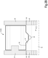
- Each sensor S1 may be arranged so as to scan a volume flush with the floor, i.e. flush with the walking surface where the machinery of the converting line is fixed, for example at a height of 0-30 cm, preferably of 1-15 cm.
- the sensors S2 and S3 are arranged so that the volume that they scan is at a greater height with respect to the floor where the machinery of the converting line is fixed.
- the volume scanned by the sensors S1 and S2 can be flush with the walking surface defined by the platforms 21, 23 or slightly above said walking surface, for example at a height of 0-30 cm, preferably 1-15 cm from the walking surface of the platforms 21, 23.
- the sensor S1 of each unwinder 1A, 1B is adapted to detect the presence of an individual or of an obstacle in area 15 (collaboration area) and area 17 (alarm area).
- the features of the sensors S1 allow distinguishing in which area there is the obstacle or the individual.
- the sensors S2 and S3 are adapted to detect the presence of an individual or an obstacle on the respective platform 21, 23, on the corresponding landing 25, 27 and on the steps 29, 31.
- Fig.2A schematically shows also a control unit 41 interfacing the sensors S1, S2, S3 and the doors 33.
- the doors may be provided with opening-closing sensors, communicating to the control unit 41 whether the door is open or closed.
- Reference number 43 indicates a generic sensor for the door 33.
- Fig.3 shows a front view of the door 33 that can be constituted by a plurality of horizontal panels hinged around a rotation axis 33A.
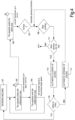
- Fig.4 shows a block diagram of the operation of the system when the unwinder 1A, 1B is in normal operating condition.
- the machine unwinder 1A, 1B
- a condition of normal operation for example unwinding a roll B1 or B2 at a working speed of 600 m/min.
- This condition is schematized in block 101.
- an operator enters the side controlled area and, more specifically, the area accessible when the line is working, i.e. the collaboration area 15.
- the sensor S1 detects the presence of the operator in the collaboration area 15 and sends a detection signal to the control unit 41.
- the control unit may be a unit dedicated to the single unwinder 1A, 1B, or to the unwinding section 1, or to a larger portion of the converting line.
- control unit 41 may intervene on the converting section with which the sensor S1 is associated, in this specific case on the unwinder 1A.
- This operation may consist in the temporary slowdown of the unwinder. In the illustrated example, the speed decreases from 600 m/min to 60 m/min.
- the unwinder 1A, 1B returns to the working speed (previous target speed).
- the signal received by the control unit 41 causes the unwinder to stop (deceleration up to 0 m/min).
- the doors 33 can be opened, or in general the opening of the doors is enabled and the unwinder is in stop condition (block 109). If the unwinder 1A, 1B is not in stop condition, the doors are locked; they cannot be opened and it is impossible to access the area with the moving machinery.
- Fig.4 From what described with reference to Fig.4 it is easily understood that the operator can move close to the unwinder 1A, 1B safely (access to the collaboration area 15) in order to observe the machinery operation without risks.
- the collaboration area may actually cover also the steps 29, 31 and the landings 25, 27. They are controlled by the sensors S2, S3 that, similarly to sensor S1, communicates with the control unit 41. In this way, the operator can move close to the raised platform 21, 23 without risks, and observe the machine from a greater height than that of the walking floor.
- the control unit 41 may check (block 203) whether, in the other unwinder, the alarm area controlled by the sensor S1 and the areas controlled by the sensors S2, S3 are free. If no, an alarm is generated (block 204) and the jog procedure is not performed. Vice versa, if the areas controlled by the sensor S1 (alarm area 17) and by the sensor S3 (platform 23) are free, it is allowed to start the jog procedure (block 207).
- Fig.8 shows a flow diagram for safely unloading, i.e. ejecting, a finished roll.
- the procedure begins (block 401) when the unwinder is not working and the doors 33 are open. The operator can perform the operations from the platform 23, for example through the pushbutton station 45.
- the ejection procedure begins in block 402.
- block 403 the presence of people is verified in the areas controlled by the sensor S1 (alarm area 17, or alarm area 17 and collaboration area 15) as well as in the area controlled by the sensor S3. In case people are present, an alarm is generated.
- the doors 33 are closed, block 404, and a further check may be performed (block 405) for verifying, through the sensors S1 and S3, that no people are present. If no people are in the controlled areas, the ejection cycle is performed for the finished roll (block 406); on the contrary, the doors 33 are opened again (block 407) and the procedure is interrupted.
Landscapes
- Engineering & Computer Science (AREA)
- General Engineering & Computer Science (AREA)
- Mechanical Engineering (AREA)
- Radar, Positioning & Navigation (AREA)
- Remote Sensing (AREA)
- Alarm Systems (AREA)
- Control Of Conveyors (AREA)
- Paper (AREA)
- Investigating Or Analysing Biological Materials (AREA)
Claims (16)
- Ein Tissue-Papier-Verarbeitungsabschnitt, der eine Verarbeitungsmaschine und ein Erkennungssystem (S1, S2, S3) zum Erkennen der Anwesenheit von Personen in der Nähe des Verarbeitungsabschnitts (1; 1A, 1B) umfasst, wobei das Erkennungssystem mindestens einen ersten Anwesenheitssensor (S1; S2, S3) umfasst, der dazu geeignet ist, die Anwesenheit von Personen in mindestens einem kontrollierten Bereich (13) zu erkennen; wobei der kontrollierte Bereich in einen zugänglichen Bereich (15), der bei Betrieb der Verarbeitungsmaschine zugänglich ist, und einen Alarmbereich (17) unterteilt ist; wobei das Erkennungssystem (S1, S2, S3) ausgebildet ist, zwischen der Anwesenheit einer Person im zugänglichen Bereich (15) und der Anwesenheit einer Person im Alarmbereich (17) zu unterscheiden; und wobei das Erkennungssystem mit einer Steuereinheit (41) verbunden ist, die dazu ausgebildet ist, auf der Grundlage von Informationen, die vom Erkennungssystem (S1, S2, S3) bereitgestellt werden, in den Betrieb des Verarbeitungsabschnitts einzugreifen; dadurch gekennzeichnet, dass die Steuereinheit (41) dazu ausgebildet ist:in den Verarbeitungsabschnitt (1; 1A, 1B) einzugreifen, um den Verarbeitungsabschnitt von einer Arbeitsgeschwindigkeit auf eine reduzierte Geschwindigkeit zu verlangsamen, wenn das Erkennungssystem (S1, S2, S3) die Anwesenheit einer Person im zugänglichen Bereich (15) erkennt, jedoch nicht die Anwesenheit einer Person im Alarmbereich (17) ;den Verarbeitungsabschnitt (1; 1A, 1B) anzuhalten, wenn das Erkennungssystem die Anwesenheit einer Person im Alarmbereich (17) erkennt.
- Abschnitt nach Anspruch 1, wobei sich der kontrollierte Bereich (13) seitlich des Verarbeitungsabschnitts erstreckt.
- Abschnitt nach Anspruch 1 oder 2, wobei der Verarbeitungsabschnitt (1) ein Abwickelabschnitt ist, der mindestens einen Abwickler (1A; 1B) zum Abwickeln von Rollen (B1, B2) aus Bahnmaterial (N) umfasst.
- Abschnitt nach einem oder mehreren der vorhergehenden Ansprüche, wobei der Alarmbereich (17) einen nicht eingezäunten Bereich zum Bewegen in Richtung des Verarbeitungsabschnitt (1; 1A, 1B) umfasst, wobei dieser nicht eingezäunte Bereich den zugänglichen Bereich (15) umfasst.
- Abschnitt nach einem oder mehreren der vorhergehenden Ansprüche, wobei das Erkennungssystem mindestens einen zweiten Anwesenheitssensor (S2, S3) umfasst, der die Anwesenheit von Personen in einem zusätzlichen kontrollierten Bereich (35; 37) erkennt, der höher angeordnet ist als der kontrollierte Bereich (13).
- Abschnitt nach Anspruch 5, wobei die Steuereinheit (41) ausgebildet ist, in den Verarbeitungsabschnitt (1; 1A, 1B) einzugreifen, wenn das Erkennungssystem (S1, S2, S3) die Anwesenheit einer Person im zusätzlichen kontrollierten Bereich (35, 37) erkennt, jedoch nicht die Anwesenheit einer Person im Alarmbereich (17), wobei dieser Eingriff den Verarbeitungsabschnitt (1; 1A, 1B) in Betrieb hält.
- Abschnitt nach einem oder mehreren der vorhergehenden Ansprüche, der mindestens einen eingezäunten Bereich (21, 23) umfasst, der mittels einer Zugangstür (33) verschlossen ist, wobei der eingezäunte Bereich durch mindestens einen zweiten Anwesenheitssensor (S2, S3) des Erkennungssystems kontrolliert wird; und wobei der zweite Anwesenheitssensor und die Zugangstür (33) eine Schnittstelle zur der Steuereinheit (41) bilden, die dazu ausgebildet ist, den Verarbeitungsabschnitt (1A, 1B) anzuhalten, wenn der Zugang einer Person zu dem eingezäunten Bereich erkannt wird.
- Abschnitt nach Anspruch 7, wenn zumindest abhängig von Anspruch 8 oder 9, wobei der eingezäunte Bereich von dem zusätzlichen kontrollierten Bereich aus betreten werden kann und wobei der zweite Anwesenheitssensor (S2, S3) die Anwesenheit von Personen in dem zusätzlichen kontrollierten Bereich und in dem eingezäunten Bereich (21, 23) erkennt.
- Abschnitt nach Anspruch 7 oder 8, wobei sich der eingezäunte Bereich sich quer zum Verarbeitungsabschnitt (1; 1A, 1B) erstreckt.
- Abschnitt nach einem oder mehreren der vorhergehenden Ansprüche, wobei jeder Anwesenheitssensor einen elektromagnetischen Wellensensor mit Betriebsreichweiten von bis zu 8,4 Metern und einer Mindestabmessung der erkennbaren Objekte von 20 mm umfasst.
- Abschnitt nach einem oder mehreren der vorhergehenden Ansprüche, wobei jeder Sensor (S1, S2, S3) so angeordnet ist, dass sein Sichtfeld über einen jeweiligen Boden des von ihm kontrollierten Bereichs gleitet.
- Abschnitt nach einem oder mehreren der vorhergehenden Ansprüche, wobei die Steuereinheit (41) so konfiguriert ist, dass, wenn das Erkennungssystem (S1, S2, S3) nach der Verlangsamung des Verarbeitungsabschnitts (1; 1A, 1B) erkennt, dass sich Personen vom zugänglichen Bereich (15) entfernen, die Steuereinheit (41) die Geschwindigkeit des Verarbeitungsabschnitts (1; 1B) erhöht.
- Abschnitt nach einem der vorhergehenden Ansprüche, wobei der Verarbeitungsabschnitt ausgewählt ist aus: einem Abschnitt zum Verschließen des hinteren Endes von Rollen, die von einem Umwickler hergestellt werden; einem Rollensammler; einer Verpackungsmaschine, beispielsweise einer Maschine zum Einwickeln, Absacken oder Palettieren von Produkten.
- Verfahren zum Steuern des Zugangs zu einem Tissue-Papier- Verarbeitungsabschnitt (1; 1A, 1B) einer Tissue-Papier- Verarbeitungsslinie, wobei der Abschnitt bewegliche Maschinen umfasst; wobei das Verfahren die Schritte umfasst:Steuern, mittels mindestens eines Anwesenheitssensors (S1, S2, S3), eines zugänglichen Bereichs (15), der bei Betrieb der Linie zugänglich ist, und eines Alarmbereichs (17);wenn eine Person den zugänglichen Bereich (15) betritt, ohne den Alarmbereich (17) zu betreten, Verlangsamen des Verarbeitungsabschnitts von einer Arbeitsgeschwindigkeit auf eine reduzierte Geschwindigkeit, welche die Fortsetzung des Betriebs des Verarbeitungsabschnitts ermöglicht;wenn eine Person den Alarmbereich (17) betritt, Anhalten des Verarbeitungsabschnitts (1; 1B).
- Verfahren nach Anspruch 14, umfassend den Schritt des Wiederbeschleunigens der Geschwindigkeit der Verarbeitungsstation auf die Arbeitsgeschwindigkeit, wenn die Person den zugänglichen Bereich (15) verlässt.
- Verfahren nach Anspruch 14 oder 15, ferner umfassend die Schritte:Geschlossen halten eines eingezäunten Bereichs, der mit dem Verarbeitungsabschnitt (1; 1A, 1B) verbunden ist, mittels einer Zugangstür (33), wenn der Verarbeitungsabschnitt arbeitet;Öffnen der Zugangstür (33), wenn der Verarbeitungsabschnitt (1; 1A, 1B) nicht arbeitet;Kontrollieren der Anwesenheit von Personen im eingezäunten Bereich mittels eines weiteren Anwesenheitssensors (S2; S3);Ermöglichen des Neustartens des Verarbeitungsabschnitts nach dem Schließen der Zugangstür, wenn der weitere Anwesenheitssensor erkennt, dass sich keine Personen im eingezäunten Bereich befinden, und der mindestens eine Anwesenheitssensor erkennt, dass sich keine Personen im Alarmbereich befinden.
Applications Claiming Priority (2)
| Application Number | Priority Date | Filing Date | Title |
|---|---|---|---|
| IT102018000009307A IT201800009307A1 (it) | 2018-10-10 | 2018-10-10 | Sistema di controllo dell'accesso a linee per la trasformazione di carta tissue e simili e metodo |
| PCT/EP2019/077315 WO2020074564A1 (en) | 2018-10-10 | 2019-10-09 | Control system for controlling the access to tissue paper converting lines and the like, and related method |
Publications (3)
| Publication Number | Publication Date |
|---|---|
| EP3864334A1 EP3864334A1 (de) | 2021-08-18 |
| EP3864334C0 EP3864334C0 (de) | 2025-04-09 |
| EP3864334B1 true EP3864334B1 (de) | 2025-04-09 |
Family
ID=65031633
Family Applications (1)
| Application Number | Title | Priority Date | Filing Date |
|---|---|---|---|
| EP19782623.3A Active EP3864334B1 (de) | 2018-10-10 | 2019-10-09 | Steuerungssystem zur steuerung des zugangs zu tissuepapierumwandlungsanlagen und dergleichen sowie entsprechendes verfahren |
Country Status (4)
| Country | Link |
|---|---|
| US (1) | US11835177B2 (de) |
| EP (1) | EP3864334B1 (de) |
| IT (1) | IT201800009307A1 (de) |
| WO (1) | WO2020074564A1 (de) |
Families Citing this family (3)
| Publication number | Priority date | Publication date | Assignee | Title |
|---|---|---|---|---|
| CN114289320B (zh) * | 2021-12-31 | 2024-03-12 | 中科微至科技股份有限公司 | 一种用于交叉带分拣系统的全自动供件系统 |
| DE102022210508A1 (de) * | 2022-10-05 | 2024-04-11 | Bhs Corrugated Maschinen- Und Anlagenbau Gmbh | Materialbahn-Abrollanordnung |
| CN117429911A (zh) * | 2023-10-20 | 2024-01-23 | 青岛中集创赢复合材料科技有限公司 | 收卷装置 |
Family Cites Families (6)
| Publication number | Priority date | Publication date | Assignee | Title |
|---|---|---|---|---|
| GB2072786A (en) * | 1981-03-28 | 1981-10-07 | Beloit Walmsley Ltd | Improvements in and relating to the guarding of paper-making machines |
| JP2002114408A (ja) * | 2000-10-05 | 2002-04-16 | Seiko Epson Corp | 印刷用紙検出装置及びプリンタ |
| US6827418B2 (en) * | 2001-06-28 | 2004-12-07 | Seiko Epson Corporation | Printing apparatus for controlling print according to printing media |
| WO2008020508A1 (fr) * | 2006-08-14 | 2008-02-21 | Kabushiki Kaisha Toshiba | dispositif ET PROCÉDÉ de traitement de feuilles |
| DE102013015838A1 (de) * | 2012-10-16 | 2014-04-17 | Heidelberger Druckmaschinen Aktiengesellschaft | Abschirmung an einer Bogen verarbeitenden Maschine, z. B. Stanze oder Druckmaschine, insbesondere im Bereich des Auslegers |
| ITUB20154638A1 (it) | 2015-10-13 | 2017-04-13 | Perini Fabio Spa | Sistema di controllo dell'accesso a macchinari di lavorazione |
-
2018
- 2018-10-10 IT IT102018000009307A patent/IT201800009307A1/it unknown
-
2019
- 2019-10-09 US US17/284,039 patent/US11835177B2/en active Active
- 2019-10-09 EP EP19782623.3A patent/EP3864334B1/de active Active
- 2019-10-09 WO PCT/EP2019/077315 patent/WO2020074564A1/en not_active Ceased
Also Published As
| Publication number | Publication date |
|---|---|
| IT201800009307A1 (it) | 2020-04-10 |
| EP3864334C0 (de) | 2025-04-09 |
| EP3864334A1 (de) | 2021-08-18 |
| WO2020074564A1 (en) | 2020-04-16 |
| US11835177B2 (en) | 2023-12-05 |
| US20210381643A1 (en) | 2021-12-09 |
Similar Documents
| Publication | Publication Date | Title |
|---|---|---|
| EP3864334B1 (de) | Steuerungssystem zur steuerung des zugangs zu tissuepapierumwandlungsanlagen und dergleichen sowie entsprechendes verfahren | |
| US11660855B2 (en) | Method and device for monitoring an access point leading into a safety zone of a roll winder or unwinder, and printing press | |
| DE102012211708B4 (de) | Rollenversorgungssystem einer Rollendruckmaschine, Rollendruckmaschine sowie Verfahren zur Bedienung eines Rollenversorgungssystems einer Rollendruckmaschine | |
| US9737992B2 (en) | Automatic automated installation | |
| US8339260B2 (en) | Securing a hazardous area in the regin surrounding the automatic loading of reels on a reel changer | |
| US7784730B2 (en) | Device for covering a danger area on a roll changer and a method for controlling a device | |
| DE102010001014A1 (de) | Rollenwechsler mit einer Absicherung eines Sicherheitsbereiches | |
| EP2354624A1 (de) | Schutzvorrichtung | |
| EP1662349B1 (de) | Absicherung von Maschinen in Abhängigkeit von deren Zustand | |
| KR101329092B1 (ko) | 탑승교 제어장치 및 이의 탑승교 제어방법 | |
| ITUB20154638A1 (it) | Sistema di controllo dell'accesso a macchinari di lavorazione | |
| CN102858665B (zh) | 具有安全装置的换卷器 | |
| IT202100025829A1 (it) | Sistema radar per controllare accessi ad un ambiente | |
| JPH0657683A (ja) | カレンダー作業者用移動台 | |
| CN102858666A (zh) | 具有安全装置的换卷器以及用于使用具有安全装置的换卷器的方法 | |
| US20060267536A1 (en) | Method and device for controlling a production unit | |
| CN107298216B (zh) | 用于操作拆包机的方法和这种拆包机 | |
| DE102006002356B4 (de) | Verfahren und Vorrichtung zur Absicherung von Gefahrbereichen in Bogendruckmaschinen | |
| EP4177509B1 (de) | Automatische maschine zur herstellung oder verpackung von verbraucherprodukten, insbesondere der tabakindustrie, und zugehöriges steuerungsverfahren | |
| JP5402981B2 (ja) | 安全装置 | |
| IT201800011076A1 (it) | Dispositivo di protezione per macchine aventi un traslatore per merci attivamente attuato, macchina industriale e metodo di controllo associato | |
| WO2025111632A1 (en) | Safety system | |
| US20120050003A1 (en) | Processing system and apparatus and method for protecting a processing system | |
| KR20250091466A (ko) | 코일 꼬임 방지장치 | |
| WO2024223267A1 (de) | Verfahren zum betreiben einer produktionslinie |
Legal Events
| Date | Code | Title | Description |
|---|---|---|---|
| STAA | Information on the status of an ep patent application or granted ep patent |
Free format text: STATUS: UNKNOWN |
|
| STAA | Information on the status of an ep patent application or granted ep patent |
Free format text: STATUS: THE INTERNATIONAL PUBLICATION HAS BEEN MADE |
|
| PUAI | Public reference made under article 153(3) epc to a published international application that has entered the european phase |
Free format text: ORIGINAL CODE: 0009012 |
|
| STAA | Information on the status of an ep patent application or granted ep patent |
Free format text: STATUS: REQUEST FOR EXAMINATION WAS MADE |
|
| 17P | Request for examination filed |
Effective date: 20210407 |
|
| AK | Designated contracting states |
Kind code of ref document: A1 Designated state(s): AL AT BE BG CH CY CZ DE DK EE ES FI FR GB GR HR HU IE IS IT LI LT LU LV MC MK MT NL NO PL PT RO RS SE SI SK SM TR |
|
| DAV | Request for validation of the european patent (deleted) | ||
| DAX | Request for extension of the european patent (deleted) | ||
| RAP3 | Party data changed (applicant data changed or rights of an application transferred) |
Owner name: KOERBER TISSUE S.P.A. |
|
| P01 | Opt-out of the competence of the unified patent court (upc) registered |
Effective date: 20230530 |
|
| RAP3 | Party data changed (applicant data changed or rights of an application transferred) |
Owner name: VALMET TISSUE CONVERTING S.P.A. |
|
| GRAP | Despatch of communication of intention to grant a patent |
Free format text: ORIGINAL CODE: EPIDOSNIGR1 |
|
| STAA | Information on the status of an ep patent application or granted ep patent |
Free format text: STATUS: GRANT OF PATENT IS INTENDED |
|
| INTG | Intention to grant announced |
Effective date: 20241111 |
|
| GRAS | Grant fee paid |
Free format text: ORIGINAL CODE: EPIDOSNIGR3 |
|
| GRAA | (expected) grant |
Free format text: ORIGINAL CODE: 0009210 |
|
| STAA | Information on the status of an ep patent application or granted ep patent |
Free format text: STATUS: THE PATENT HAS BEEN GRANTED |
|
| AK | Designated contracting states |
Kind code of ref document: B1 Designated state(s): AL AT BE BG CH CY CZ DE DK EE ES FI FR GB GR HR HU IE IS IT LI LT LU LV MC MK MT NL NO PL PT RO RS SE SI SK SM TR |
|
| REG | Reference to a national code |
Ref country code: GB Ref legal event code: FG4D |
|
| REG | Reference to a national code |
Ref country code: CH Ref legal event code: EP |
|
| REG | Reference to a national code |
Ref country code: DE Ref legal event code: R096 Ref document number: 602019068451 Country of ref document: DE |
|
| REG | Reference to a national code |
Ref country code: IE Ref legal event code: FG4D |
|
| U01 | Request for unitary effect filed |
Effective date: 20250507 |
|
| U07 | Unitary effect registered |
Designated state(s): AT BE BG DE DK EE FI FR IT LT LU LV MT NL PT RO SE SI Effective date: 20250513 |
|
| P04 | Withdrawal of opt-out of the competence of the unified patent court (upc) registered |
Free format text: CASE NUMBER: APP_22076/2025 Effective date: 20250509 |
|
| PG25 | Lapsed in a contracting state [announced via postgrant information from national office to epo] |
Ref country code: ES Free format text: LAPSE BECAUSE OF FAILURE TO SUBMIT A TRANSLATION OF THE DESCRIPTION OR TO PAY THE FEE WITHIN THE PRESCRIBED TIME-LIMIT Effective date: 20250409 |
|
| PG25 | Lapsed in a contracting state [announced via postgrant information from national office to epo] |
Ref country code: NO Free format text: LAPSE BECAUSE OF FAILURE TO SUBMIT A TRANSLATION OF THE DESCRIPTION OR TO PAY THE FEE WITHIN THE PRESCRIBED TIME-LIMIT Effective date: 20250709 Ref country code: GR Free format text: LAPSE BECAUSE OF FAILURE TO SUBMIT A TRANSLATION OF THE DESCRIPTION OR TO PAY THE FEE WITHIN THE PRESCRIBED TIME-LIMIT Effective date: 20250710 |
|
| PG25 | Lapsed in a contracting state [announced via postgrant information from national office to epo] |
Ref country code: PL Free format text: LAPSE BECAUSE OF FAILURE TO SUBMIT A TRANSLATION OF THE DESCRIPTION OR TO PAY THE FEE WITHIN THE PRESCRIBED TIME-LIMIT Effective date: 20250409 |
|
| PGFP | Annual fee paid to national office [announced via postgrant information from national office to epo] |
Ref country code: GB Payment date: 20250923 Year of fee payment: 7 |
|
| PG25 | Lapsed in a contracting state [announced via postgrant information from national office to epo] |
Ref country code: HR Free format text: LAPSE BECAUSE OF FAILURE TO SUBMIT A TRANSLATION OF THE DESCRIPTION OR TO PAY THE FEE WITHIN THE PRESCRIBED TIME-LIMIT Effective date: 20250409 |
|
| PG25 | Lapsed in a contracting state [announced via postgrant information from national office to epo] |
Ref country code: RS Free format text: LAPSE BECAUSE OF FAILURE TO SUBMIT A TRANSLATION OF THE DESCRIPTION OR TO PAY THE FEE WITHIN THE PRESCRIBED TIME-LIMIT Effective date: 20250709 |
|
| PG25 | Lapsed in a contracting state [announced via postgrant information from national office to epo] |
Ref country code: IS Free format text: LAPSE BECAUSE OF FAILURE TO SUBMIT A TRANSLATION OF THE DESCRIPTION OR TO PAY THE FEE WITHIN THE PRESCRIBED TIME-LIMIT Effective date: 20250809 |
|
| U20 | Renewal fee for the european patent with unitary effect paid |
Year of fee payment: 7 Effective date: 20250925 |
|
| PG25 | Lapsed in a contracting state [announced via postgrant information from national office to epo] |
Ref country code: SM Free format text: LAPSE BECAUSE OF FAILURE TO SUBMIT A TRANSLATION OF THE DESCRIPTION OR TO PAY THE FEE WITHIN THE PRESCRIBED TIME-LIMIT Effective date: 20250409 |
|
| PG25 | Lapsed in a contracting state [announced via postgrant information from national office to epo] |
Ref country code: CZ Free format text: LAPSE BECAUSE OF FAILURE TO SUBMIT A TRANSLATION OF THE DESCRIPTION OR TO PAY THE FEE WITHIN THE PRESCRIBED TIME-LIMIT Effective date: 20250409 |
|
| PG25 | Lapsed in a contracting state [announced via postgrant information from national office to epo] |
Ref country code: SK Free format text: LAPSE BECAUSE OF FAILURE TO SUBMIT A TRANSLATION OF THE DESCRIPTION OR TO PAY THE FEE WITHIN THE PRESCRIBED TIME-LIMIT Effective date: 20250409 |
|
| PLBE | No opposition filed within time limit |
Free format text: ORIGINAL CODE: 0009261 |
|
| STAA | Information on the status of an ep patent application or granted ep patent |
Free format text: STATUS: NO OPPOSITION FILED WITHIN TIME LIMIT |
|
| REG | Reference to a national code |
Ref country code: CH Ref legal event code: L10 Free format text: ST27 STATUS EVENT CODE: U-0-0-L10-L00 (AS PROVIDED BY THE NATIONAL OFFICE) Effective date: 20260218 |
|
| 26N | No opposition filed |
Effective date: 20260112 |