EP3864288B1 - Windkraftanlage - Google Patents
Windkraftanlage Download PDFInfo
- Publication number
- EP3864288B1 EP3864288B1 EP19783529.1A EP19783529A EP3864288B1 EP 3864288 B1 EP3864288 B1 EP 3864288B1 EP 19783529 A EP19783529 A EP 19783529A EP 3864288 B1 EP3864288 B1 EP 3864288B1
- Authority
- EP
- European Patent Office
- Prior art keywords
- opening
- flow
- structural element
- hollow structural
- platform
- Prior art date
- Legal status (The legal status is an assumption and is not a legal conclusion. Google has not performed a legal analysis and makes no representation as to the accuracy of the status listed.)
- Active
Links
Images




Classifications
-
- F—MECHANICAL ENGINEERING; LIGHTING; HEATING; WEAPONS; BLASTING
- F03—MACHINES OR ENGINES FOR LIQUIDS; WIND, SPRING, OR WEIGHT MOTORS; PRODUCING MECHANICAL POWER OR A REACTIVE PROPULSIVE THRUST, NOT OTHERWISE PROVIDED FOR
- F03D—WIND MOTORS
- F03D13/00—Assembly, mounting or commissioning of wind motors; Arrangements specially adapted for transporting wind motor components
- F03D13/20—Arrangements for mounting or supporting wind motors; Masts or towers for wind motors
-
- F—MECHANICAL ENGINEERING; LIGHTING; HEATING; WEAPONS; BLASTING
- F03—MACHINES OR ENGINES FOR LIQUIDS; WIND, SPRING, OR WEIGHT MOTORS; PRODUCING MECHANICAL POWER OR A REACTIVE PROPULSIVE THRUST, NOT OTHERWISE PROVIDED FOR
- F03D—WIND MOTORS
- F03D13/00—Assembly, mounting or commissioning of wind motors; Arrangements specially adapted for transporting wind motor components
- F03D13/20—Arrangements for mounting or supporting wind motors; Masts or towers for wind motors
- F03D13/25—Arrangements for mounting or supporting wind motors; Masts or towers for wind motors specially adapted for offshore installation
-
- E—FIXED CONSTRUCTIONS
- E04—BUILDING
- E04H—BUILDINGS OR LIKE STRUCTURES FOR PARTICULAR PURPOSES; SWIMMING OR SPLASH BATHS OR POOLS; MASTS; FENCING; TENTS OR CANOPIES, IN GENERAL
- E04H12/00—Towers; Masts or poles; Chimney stacks; Water-towers; Methods of erecting such structures
- E04H12/003—Access covers or locks therefor
-
- E—FIXED CONSTRUCTIONS
- E04—BUILDING
- E04H—BUILDINGS OR LIKE STRUCTURES FOR PARTICULAR PURPOSES; SWIMMING OR SPLASH BATHS OR POOLS; MASTS; FENCING; TENTS OR CANOPIES, IN GENERAL
- E04H12/00—Towers; Masts or poles; Chimney stacks; Water-towers; Methods of erecting such structures
- E04H12/02—Structures made of specified materials
- E04H12/08—Structures made of specified materials of metal
-
- F—MECHANICAL ENGINEERING; LIGHTING; HEATING; WEAPONS; BLASTING
- F03—MACHINES OR ENGINES FOR LIQUIDS; WIND, SPRING, OR WEIGHT MOTORS; PRODUCING MECHANICAL POWER OR A REACTIVE PROPULSIVE THRUST, NOT OTHERWISE PROVIDED FOR
- F03D—WIND MOTORS
- F03D80/00—Details, components or accessories not provided for in groups F03D1/00 - F03D17/00
- F03D80/80—Arrangement of components within nacelles or towers
- F03D80/82—Arrangement of components within nacelles or towers of electrical components
- F03D80/85—Cabling
-
- E—FIXED CONSTRUCTIONS
- E02—HYDRAULIC ENGINEERING; FOUNDATIONS; SOIL SHIFTING
- E02B—HYDRAULIC ENGINEERING
- E02B17/00—Artificial islands mounted on piles or like supports, e.g. platforms on raisable legs or offshore constructions; Construction methods therefor
- E02B2017/0091—Offshore structures for wind turbines
-
- F—MECHANICAL ENGINEERING; LIGHTING; HEATING; WEAPONS; BLASTING
- F03—MACHINES OR ENGINES FOR LIQUIDS; WIND, SPRING, OR WEIGHT MOTORS; PRODUCING MECHANICAL POWER OR A REACTIVE PROPULSIVE THRUST, NOT OTHERWISE PROVIDED FOR
- F03D—WIND MOTORS
- F03D80/00—Details, components or accessories not provided for in groups F03D1/00 - F03D17/00
- F03D80/60—Cooling or heating of wind motors
-
- F—MECHANICAL ENGINEERING; LIGHTING; HEATING; WEAPONS; BLASTING
- F03—MACHINES OR ENGINES FOR LIQUIDS; WIND, SPRING, OR WEIGHT MOTORS; PRODUCING MECHANICAL POWER OR A REACTIVE PROPULSIVE THRUST, NOT OTHERWISE PROVIDED FOR
- F03D—WIND MOTORS
- F03D9/00—Adaptations of wind motors for special use; Combinations of wind motors with apparatus driven thereby; Wind motors specially adapted for installation in particular locations
- F03D9/20—Wind motors characterised by the driven apparatus
- F03D9/25—Wind motors characterised by the driven apparatus the apparatus being an electrical generator
- F03D9/255—Wind motors characterised by the driven apparatus the apparatus being an electrical generator connected to electrical distribution networks; Arrangements therefor
-
- F—MECHANICAL ENGINEERING; LIGHTING; HEATING; WEAPONS; BLASTING
- F05—INDEXING SCHEMES RELATING TO ENGINES OR PUMPS IN VARIOUS SUBCLASSES OF CLASSES F01-F04
- F05B—INDEXING SCHEME RELATING TO WIND, SPRING, WEIGHT, INERTIA OR LIKE MOTORS, TO MACHINES OR ENGINES FOR LIQUIDS COVERED BY SUBCLASSES F03B, F03D AND F03G
- F05B2240/00—Components
- F05B2240/90—Mounting on supporting structures or systems
- F05B2240/95—Mounting on supporting structures or systems offshore
-
- F—MECHANICAL ENGINEERING; LIGHTING; HEATING; WEAPONS; BLASTING
- F05—INDEXING SCHEMES RELATING TO ENGINES OR PUMPS IN VARIOUS SUBCLASSES OF CLASSES F01-F04
- F05B—INDEXING SCHEME RELATING TO WIND, SPRING, WEIGHT, INERTIA OR LIKE MOTORS, TO MACHINES OR ENGINES FOR LIQUIDS COVERED BY SUBCLASSES F03B, F03D AND F03G
- F05B2260/00—Function
- F05B2260/20—Heat transfer, e.g. cooling
-
- F—MECHANICAL ENGINEERING; LIGHTING; HEATING; WEAPONS; BLASTING
- F05—INDEXING SCHEMES RELATING TO ENGINES OR PUMPS IN VARIOUS SUBCLASSES OF CLASSES F01-F04
- F05B—INDEXING SCHEME RELATING TO WIND, SPRING, WEIGHT, INERTIA OR LIKE MOTORS, TO MACHINES OR ENGINES FOR LIQUIDS COVERED BY SUBCLASSES F03B, F03D AND F03G
- F05B2270/00—Control
- F05B2270/30—Control parameters, e.g. input parameters
- F05B2270/303—Temperature
-
- Y—GENERAL TAGGING OF NEW TECHNOLOGICAL DEVELOPMENTS; GENERAL TAGGING OF CROSS-SECTIONAL TECHNOLOGIES SPANNING OVER SEVERAL SECTIONS OF THE IPC; TECHNICAL SUBJECTS COVERED BY FORMER USPC CROSS-REFERENCE ART COLLECTIONS [XRACs] AND DIGESTS
- Y02—TECHNOLOGIES OR APPLICATIONS FOR MITIGATION OR ADAPTATION AGAINST CLIMATE CHANGE
- Y02E—REDUCTION OF GREENHOUSE GAS [GHG] EMISSIONS, RELATED TO ENERGY GENERATION, TRANSMISSION OR DISTRIBUTION
- Y02E10/00—Energy generation through renewable energy sources
- Y02E10/70—Wind energy
- Y02E10/72—Wind turbines with rotation axis in wind direction
-
- Y—GENERAL TAGGING OF NEW TECHNOLOGICAL DEVELOPMENTS; GENERAL TAGGING OF CROSS-SECTIONAL TECHNOLOGIES SPANNING OVER SEVERAL SECTIONS OF THE IPC; TECHNICAL SUBJECTS COVERED BY FORMER USPC CROSS-REFERENCE ART COLLECTIONS [XRACs] AND DIGESTS
- Y02—TECHNOLOGIES OR APPLICATIONS FOR MITIGATION OR ADAPTATION AGAINST CLIMATE CHANGE
- Y02E—REDUCTION OF GREENHOUSE GAS [GHG] EMISSIONS, RELATED TO ENERGY GENERATION, TRANSMISSION OR DISTRIBUTION
- Y02E10/00—Energy generation through renewable energy sources
- Y02E10/70—Wind energy
- Y02E10/727—Offshore wind turbines
-
- Y—GENERAL TAGGING OF NEW TECHNOLOGICAL DEVELOPMENTS; GENERAL TAGGING OF CROSS-SECTIONAL TECHNOLOGIES SPANNING OVER SEVERAL SECTIONS OF THE IPC; TECHNICAL SUBJECTS COVERED BY FORMER USPC CROSS-REFERENCE ART COLLECTIONS [XRACs] AND DIGESTS
- Y02—TECHNOLOGIES OR APPLICATIONS FOR MITIGATION OR ADAPTATION AGAINST CLIMATE CHANGE
- Y02E—REDUCTION OF GREENHOUSE GAS [GHG] EMISSIONS, RELATED TO ENERGY GENERATION, TRANSMISSION OR DISTRIBUTION
- Y02E10/00—Energy generation through renewable energy sources
- Y02E10/70—Wind energy
- Y02E10/728—Onshore wind turbines
Definitions
- the subject matter concerns an offshore wind turbine.
- Wind farms especially offshore wind farms, usually have to be connected to an energy supply network via a substation.
- a substation can be arranged directly on a wind turbine or as a transformer station within the wind farm.
- a monopile is a common design for the foundation structure of a wind turbine.
- a monopile can have cable entries for submarine cables to connect the wind turbines to each other and/or to a transformer station.
- substations in offshore wind farms are established using so-called jackets.
- so-called J-tubes are used, which are arranged on the outside of the jackets and which guide the submarine cables.
- J-Tubes have also been used to guide the submarine cables when founding substations using monopiles.
- the use of J-Tubes is complex, error-prone and cost-intensive, so solutions are being sought to avoid this.
- the submarine cables are guided upwards within the monopile via the cable entries and mechanically attached to a lower platform using cable hang-offs.
- a platform also called an air tight deck, offers the possibility of electrically wiring the submarine cables.
- the submarine cables that are used are usually armored cables, which are armored with a metallic sheath, in particular a steel sheath.
- the steel jacket is cast in the cable hang-off and clamped around the cable to the air thight deck to attach.
- an increased number of cables especially when several wind turbines are connected to a substation, can lead to temperature problems within a monopile. Joule heat is generated in the cables due to ohmic losses. This heat must be dissipated at the monopile. In particular, a rated conductor temperature of 90°C must not be exceeded.
- the EP 2 568 169 A1 describes an air conditioning system for the switching technology within a wind turbine. Fresh air and waste heat are used to air-condition the installed components. However, the cables installed within the foundation tower are not taken into account.
- the object was to avoid overheating of cables in a wind turbine or its foundation structure.
- the wind turbine has a foundation structure, in particular a hollow structural element.
- the hollow structural element can in particular be designed as a monopile, tripile, tripod or heavyweight foundation with monopile.
- the hollow structural element can also be founded on a floating basis.
- At least one cable entry is provided in a bottom area of the hollow structural element, which when installed is below the water level (Lowest Astronomical Tide, LAT).
- a separate cable entry can be provided for each cable to be inserted into the hollow structural element. More than 2, preferably more than 5, in particular 7 to 8 cables, preferably up to a maximum of 12 cables, can be routed within the hollow structural element, so that a corresponding number of cable entries can be provided.
- the cables can be both medium voltage cables and high voltage cables. Corresponding cable cross sections can be given.
- the cable entries in the installed state can preferably be 1m to 5m above the ground, in particular the seabed.
- a scour protection can be installed below the cable entries be provided and the cable entries are preferably above the scour protection.
- a first platform is arranged within the hollow structural element, above the water level (Lowest Astronomical Tide, LAT).
- This first platform can in particular be an air tight deck. Cable hang-offs to which the cables are attached can be provided on the first platform.
- Cooling the cables is problematic. Since several cables are routed simultaneously in the hollow structural element, as explained above, the interior of the monopile heats up significantly. Since the exchange of cooling medium between the interior and exterior of the hollow structural element is impaired by the walls of the hollow structural element, the waste heat from the cables may not be sufficiently dissipated. For this reason, an active control element is proposed that effects a media exchange between the interior of the hollow structural element and the exterior of the hollow structural element.
- a medium can in particular be air and/or water.
- the medium is in particular the ambient air of the hollow structural element and/or the sea water washing around the hollow structural element.
- the lateral surface of the hollow structural element can be the outer skin of the hollow structural element. This can in particular be a sheet of metal, in particular a steel sheet.
- the flow opening connects the interior of the hollow structural element with the exterior of the hollow structural element.
- the flow opening can be a bore or another recess in the lateral surface. Outside air can flow into the interior of the hollow structural element via the flow opening. Heated internal air can flow from the interior of the hollow structural element to the outside via the flow opening. If following When we talk about air or ventilation, this refers to the medium of air. The statements then also apply to water, which can flow as a medium through the flow opening into the hollow structural element and out of the hollow structural element.
- the exchange of medium between the interior and exterior of the hollow structural element can be actively influenced, in particular controlled or regulated.
- the flow speed, the flow volume, the flow direction and/or the flow pressure are actively influenced by the control element. This means that the control element can influence how and to what extent the medium (air and/or water) flows through the hollow structural element along the cables in order to achieve a cooling effect on the cables.
- the hollow structural element can be a monopile.
- the hollow structural element can be floating or founded in the ground. It is also possible for the hollow structural element to be a tripile or tripod. Other hollow structural elements are also conceivable. With the hollow structural elements, the cables can be routed inside, so that J-tubes are no longer necessary.
- the wind turbine in question can in particular be a transformer station, also called a transformer station or substation. Cables from a number of wind turbines in a wind farm converge in a substation. These cables are preferably guided into the interior of the hollow structural element via the cable entry. The inside of the hollow structural element is cooled through the flow opening. It is also possible that the wind turbine is a wind turbine. In the wind turbine, several cables can be routed within the hollow structural element, which can actually be cooled via the flow opening.
- Flow openings can be provided on the outer skin of the hollow structural element.
- the at least one control element can be arranged on at least one of these openings.
- At least one flow opening can be arranged above the platform in the hollow structural element. In such a case, the medium must be guided through the platform to the interior of the hollow structural element below the platform. However, the platform can serve to accommodate the control element so that it can be easily mounted in the hollow structural element.
- At least one flow opening can also be arranged below the platform in the hollow structural element. The medium can then flow directly through the outer skin and reach the cables.
- the control element can be arranged directly at the flow opening.
- the media flow through the flow opening can be influenced directly by the control element.
- Changing the setting of the control element has a direct influence on the flow behavior of the medium through the flow opening.
- the flow opening is fluidly connected to the interior of the hollow structural element below the platform via a pipe (ventilation pipe in the case of air, flow pipe in the case of water).
- a pipe ventilation pipe in the case of air, flow pipe in the case of water.
- the active corrosion protection system can be located below the platform. This creates chlorine gases. With a ventilation system, these must not reach accessible areas. This means that the ventilation pipes must be designed to be as gas-tight as possible right up to the outlet opening.
- control element is arranged between the flow opening and the tube, between the flow opening and the interior of the hollow structural element or outside on the flow opening. If the control element is arranged between the flow opening and the pipe, the medium can flow through the flow opening and the control element into the pipe. In this case, the medium flow in the pipe can be influenced by the control element. In particular, a flow volume through the pipe can be increased compared to a natural flow, for example caused by wind.
- the control element can also be arranged in the interior of the hollow structural element and thus be protected from environmental influences. If the control element is arranged on the outside of the flow opening, it can be maintained particularly easily. This applies in particular if the flow opening is located below the platform, since the opening would otherwise no longer be accessible from the inside after the hollow structural element has been installed.
- At least one flow opening is an outflow opening and/or that at least one flow opening is an inflow opening.
- Medium can be guided into the interior of the hollow structural element through an inflow opening.
- Medium can be directed from the interior of the hollow structural element to the outside via an outflow opening.
- the control element can be a fan, in particular a blower.
- the fan can suck in outside air via the flow opening and blow it into the ventilation pipe or the interior of the hollow structural element.
- the fan can suck in internal air via the flow opening and blow it out to the outside.
- the fan enables increased air exchange. This promotes the cooling performance of the system.
- a fan, a nozzle or a propeller can also serve as a control element.
- a nozzle or a propeller can be useful, especially with water.
- control element is a controllable flap and/or shutter.
- the flap and/or closure can be opened or closed and, for example, can be moved stepwise or continuously in at least two positions between an open position and a closed position. This allows the flow cross section at the flow opening to be varied. Adjusting the flap and/or closure also means that it can be freed from encrustations and/or growths and/or maritime growth. The adjustment can be done by motor, in particular by electric motor, or manually, in particular via sliding doors or lens shutters.
- the flow opening can be closed by a grid or a net, which is permeable to the medium but impermeable to larger objects such as flotsam or animals. This prevents dirt or animals from getting into the interior of the hollow structural element.
- the flow openings above the water level can be angled downwards on the outside to avoid the ingress of rainwater.
- the platform is preferably designed with cable hang-offs, so that it has a cable suspension that accommodates the cables inserted into the hollow structural element through the cable entry.
- a first bottom-side opening is provided in the platform. This first opening is in the area of the flow opening and in particular in the area of the ventilation pipe.
- the ventilation pipe is preferably arranged directly at the first opening.
- the platform is preferably an air tight deck, which has no other openings apart from the suggested bottom openings and a maintenance hatch.
- the air tight deck is in particular essentially airtight and divides the hollow structural element into a bottom area and a head area. The The head area is above the platform and the bottom area is below the platform.
- the flow opening is fluidly connected to the ventilation pipe via the first opening. Air can thus flow from the flow opening through the first opening into the ventilation pipe and ensure cooling of the cables in the floor area.
- the (ventilation) pipe extends along the longitudinal axis of the hollow structural element. This enables the cables to be cooled along the longitudinal axis of the hollow structural element.
- the (ventilation) pipe can be arranged on an inner wall of the hollow structural element.
- the (ventilation) pipe can run parallel to the longitudinal axis of the hollow structural element. It is also possible for the hollow structural element to be helically encircling the longitudinal axis of the hollow structural element.
- the (ventilation) pipe can be arranged on the inner wall of the hollow structural element.
- the ventilation pipe is preferably arranged so as to extend vertically on the inner wall of the hollow structural element.
- the ventilation pipe can also be arranged freely hanging on the underside of the air tight deck.
- the (ventilation) pipe has outflow openings at distances from one another, in particular at regular distances from one another.
- the supply air/water can flow from the (ventilation) pipe into the interior of the hollow structural element via these outflow openings and thus cool the air/water there.
- the outflow openings ensure that the supply air/water flows into the interior of the hollow structural element as evenly distributed as possible.
- the outflow openings of the (ventilation) pipe are formed as slots or bores and/or that the outflow openings of the (ventilation) pipe are directed towards the center of the Hollow structural element are directed.
- the (ventilation) pipe is arranged in the area or directly on the inner wall of the hollow structural element.
- the cables usually hang in the middle of the hollow structural element so that the incoming air/water flows as radially inwards as possible. Therefore, the outflow openings are preferably directed towards the center of the hollow structural element.
- the (ventilation) pipe can also be arranged centrally in the hollow structural element and the ventilation openings can point radially outwards. The incoming air/water can then be blown out in all directions.
- the supply air can flow out via a bottom opening of the ventilation pipe or a bottom-side outflow opening.
- the ventilation pipe can have a bottom with an outflow opening or can be formed without a bottom and open at the bottom. In both cases, the supply air flows out.
- the ventilation pipe ends on the bottom side in the installed state at a distance from a sea water level.
- the distance is preferably a few meters above LAT. In particular, the distance is less than 21m above LAT.
- the distance is selected in particular depending on the tidal range of the installation location of the hollow structural element. The distance should preferably be chosen so that at HAT (highest astronomical tide) a certain distance is still guaranteed between the bottom side of the ventilation pipe and the water level.
- At least one flow opening is arranged in the hollow structural element in the manner of an outflow opening. It is possible for the outflow opening to be arranged above or below the platform. A plurality of outflow openings can also be provided along the vertical axis or along the circumference of the hollow structural element. This can, if necessary, achieve a uniform flow of the heated medium.
- a plurality of flow openings can also be formed as inflow openings.
- the inflow openings can be provided along the vertical axis or along the circumference of the hollow structural element. This can optionally achieve a uniform flow of fresh medium into the hollow structural element.
- the platform has a second opening on the bottom, particularly in the area of the outflow opening.
- the outflow opening is fluidly connected to the interior of the hollow structural element below the platform via the second opening. Air can thus flow via the second opening from the interior of the hollow structural element below the platform to the outflow opening and from there be discharged to the outside.
- At least one temperature sensor is arranged inside the hollow structural element below the platform. This temperature sensor makes it possible to detect whether the cables are below the rated conductor temperature.
- the temperature sensor can be used to at least control or regulate the control element.
- one or both fans can be switched on (or a fan flap and/or shutter can be opened) in a control system, and if the temperature falls below at least one of the fans can be switched off (or a fan flap and/or - clasp must be closed). Switching on and off or opening and closing the control element depending on the temperature can be controlled via hysteresis. It is also possible that, depending on the temperature, the performance of one or both fans is regulated or the degree of opening of a fan flap and/or - closure is regulated. A P, PI or PID control of the control element depending on the temperature is possible.
- At least one current sensor is arranged on at least one of the cables. This current sensor makes it possible to determine whether the Joule heat emitted by the cables makes cooling necessary or not.
- the current sensor can be used to at least control or regulate the control element.
- one or both fans can be switched on (or a flap and/or shutter can be opened) in a control system, and if the current intensity falls below, at least one of the fans can be switched off (or a flap and/or, for example). -clasp can be closed).
- the switching on and off or opening and closing of the control element depending on the current strength can be controlled depending on the current strength, in particular via hysteresis. It is also possible for the power of the control element, in particular one or both fans, to be regulated or for the degree of opening of a flap and/or closure to be regulated depending on the current strength.
- a P, PI or PID regulation of the control element depending on the current strength is possible.
- Cooling of the interior of the hollow structural element below the platform is necessary, particularly in the summer months. In the winter months, the cables may become more heated due to the greater power. In order to use the Joule heat of the lines, it is possible to lead this waste heat not to the outside via the exhaust air openings, but to the interior of the hollow structural element above the platform, in particular into the technical devices arranged there, in particular the substation. For this reason it is A flow valve is provided at the exhaust air opening. This flow valve can in particular be a 3/2 flow valve.
- an inlet of the flow valve is fluidly connected to the second opening and/or the fan. Medium thus flows into the flow valve from the interior of the hollow structural element below the platform via the inlet.
- a first outlet of the flow valve may be fluidly connected to the outlet opening and a second outlet of the flow valve may be fluidly connected to the interior of the hollow structural member above the platform.
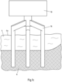
- Fig. 1a shows a monopile 2 as a hollow structural element.
- the monopile 2 is founded on the open sea 4 on the lake bed 6.
- the monopile 2 stands beyond LAT 4a and is connected to a wind turbine system, for example a substation 10, via a transition piece 8.
- a monopile 2 is provided, which, however, is floating and is founded in the lake bed 6 via anchors 12.
- another tower 14, which carries a wind turbine, for example, is attached to the transition piece 8.
- a tripile 16 serves as a support for a substation 10 and is founded in the ground 6.
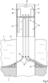
- Fig. 2 shows a monopile 2 which is founded in the ground 6. Above a scour protection 18, approximately at a distance of 1m to 5m above the floor 6, there are cable entries 20. Submarine cables 22 are guided into the interior of the monopile 2 through the cable entries 20. The submarine cables 22 are armored cables, for example with steel reinforcement. These are guided within the monopile from the cable entries 20 to a first platform 24. The submarine cables 22 are suspended from the platform 24 via cable suspensions (not shown). The platform 24 is also referred to as an air tight deck, since the submarine cables 22 are guided essentially in isolation from the underside of the platform 24 to the top of the platform 24. If necessary, the submarine cables 22 can be connected on the top of the platform 24, for example with a transformer station not shown.
- the submarine cables within the monopile 2 below the platform 24 be cooled via a ventilation pipe 26.
- a flow opening 28 is provided in the monopile 2 above the platform 24.
- the flow opening 28 breaks through the outer skin of the monopile so that air can flow from the outside to the inside.
- a fan 30 is arranged at the flow opening 28.
- This blower 30 is fluidly connected at its inlet to the flow opening 28 and at its outlet via a first opening in the platform 24 to the ventilation pipe 26. Through the blower 30, air is sucked in from outside via the flow opening 28 and into the interior via the ventilation pipe 26 of the monopile 2 under the platform 24. This creates a cooling effect on the cable 22.
- a flow opening is provided as an exhaust air opening 32, also breaking through the outer skin of the monopile 2.
- a fan 34 is provided at the exhaust opening 32.
- the fan 34 is connected to the interior space below the platform 24 via a second opening in the platform 24 with an inlet.
- the outlet of the blower 34 is at least fluidly connected to the exhaust air opening 32, so that air is sucked in via the blower 34 from the interior of the monopile 2 below the platform 24 and is blown outwards via the exhaust air opening 32. This creates an air flow in the interior of the monopile 2 below the platform 24, which is used to transport heated air away. This achieves optimized cooling of the submarine cable 22.
- the fans 30, 34 can be controlled via a processor 36.
- the processor can be connected to temperature sensors 38 (not shown) arranged within the monopile 2 below the platform 24. The connection can be wired or wireless.
- the processor 36 can also regulate the fans 30, 34. In particular, a P, PI or PID control can be carried out, with which the power of the fans 30, 34 can be adjusted.
- the processor 36 can also have a current intensity, which can be measured using a current sensor (shown as an example in Fig. 7 ) is measured, causing the fans 30, 34 to be regulated.
- Fig. 3 shows a variant in which the heated air from the interior of the monopile 2 is not necessarily blown out via the exhaust opening 32, but can be used for heating purposes, for example in the winter months.
- An inlet 32a of the blower 34 can be connected to the interior of the monopile 2 below Platform 24 be connected.
- An outlet 32b of the fan 34 may be connected to a flow valve 42.
- the flow valve 42 may be a 3/2 valve with an inlet 42a and two outlets 42b.
- a first outlet 42b may be fluidly connected to the exhaust opening 32 and a second outlet 42b may be be connected via an opening 40 to the interior of the monopile 2 above the platform 24.
- the heated air sucked in via the inlet 32a can either be blown outwards via the exhaust air opening 32 or via the opening 40 into the interior of the monopile 2 and protect technical systems there from frost damage.
- Fig. 4a, b show a wide variety of shapes of flow openings 28. Exhaust openings 32 can be designed accordingly. It can be seen that the flow openings 28 are arranged above the platform 24 on the outer skin of the monopile 2. The flow openings 28 can be through several openings as in Fig. 4a shown to be formed or a single opening, as in Fig. 4b is shown to be.
- the ventilation pipe 26 is preferably arranged parallel to the longitudinal axis of the monopile 2 on an inner wall of the outer skin of the monopile 2. According to the Fig. 2 the ventilation pipe 26 runs vertically in the installed position. Another arrangement shows this Fig. 5 .
- the ventilation pipe 26 is arranged in a helix shape all around the inner wall of the outer skin of the monopile 2. This enables a more even distribution of the sucked-in supply air within the monopile 2.
- Openings 26a can be provided in the ventilation pipe 26, such as Fig. 6 shows.
- the openings 26b can, for example, be slot-shaped at regular intervals from one another.
- the openings 26a can be shaped pointing towards the central axis of the monopile 2. The sucked air flows from the ventilation pipe into the interior of the monopile 2 via the openings 26a.
- Fig. 7 shows an exemplary embodiment in which, instead of the ventilation pipe, cooling medium flows through the monopile 2 directly via the flow openings 28, 32. It can be seen that flow openings 28, 32 can be arranged below the platform 24 in the outer skin of the monopile 2 above LAT 4a and / or below LAT.
- a fan 30, 34 can be arranged inside the monopile 2 and/or outside the monopile 2, as shown.
- the blower 30, 34 can be arranged directly on a flow opening 28, 30.
- a propeller or nozzle 30a, 34a can be arranged inside the monopile 2 and/or outside the monopile 2, as shown.
- the blower 30a, 34a can be arranged directly on a flow opening 28, 30.
- a current sensor 44 can be arranged on one or more cables 22. This can be, for example, a Rogowski coil. In this way, a current intensity in the cables 22 can be measured and this can be used to control the control devices such as fans 30, 34, propellers 30a, 34a or fan flaps and/or shutters 30b, 34b (shown below) via the processor 36.
- the control devices such as fans 30, 34, propellers 30a, 34a or fan flaps and/or shutters 30b, 34b (shown below) via the processor 36.
- Figs. 8a-c show different positions of laterally pivotable fan flaps and/or closures 30a, which are pivotally arranged on the inside or outside of the monopile 2 at a flow opening 28, 32.
- Fig. 8a shows a closed position
- Fig. 8b shows an intermediate position
- Fig. 8c shows an open position.
- the flow cross section in the flow opening 28, 32 changes, so that a flow of medium (air and/or water) can be influenced.
- the position can be adjusted by the processor 36, in particular controlled by the measured temperature or the measured current.
- Fig. Figs. 9a-c show different positions of forward-pivoting fan flap and/or closure 30a, which are inside or outside on the monopile 2 a flow opening 28, 32 are arranged.
- Fig. 9a shows a closed position
- Fig. 9b shows an intermediate position
- Fig. 9c shows an open position.
- the flow cross section in the flow opening 28, 32 changes, so that a flow of medium (air and/or water) can be influenced.
- the position can be adjusted by the processor 36, in particular controlled by the measured temperature or the measured current.
Landscapes
- Engineering & Computer Science (AREA)
- Life Sciences & Earth Sciences (AREA)
- Chemical & Material Sciences (AREA)
- General Engineering & Computer Science (AREA)
- Sustainable Energy (AREA)
- Mechanical Engineering (AREA)
- Combustion & Propulsion (AREA)
- Sustainable Development (AREA)
- Architecture (AREA)
- Structural Engineering (AREA)
- Civil Engineering (AREA)
- Physics & Mathematics (AREA)
- Thermal Sciences (AREA)
- Wood Science & Technology (AREA)
- Materials Engineering (AREA)
- Wind Motors (AREA)
- Ventilation (AREA)
Description
- Der Gegenstand betrifft eine Offshore-Windkraftanlage.
- Windparks, insbesondere Offshore-Windparks, müssen in der Regel über eine Umspannstation an ein Energieversorgungsnetz angeschlossen werden. Dabei kann eine Umspannstation unmittelbar an einer Windturbine oder als Trafostation innerhalb des Windparks angeordnet sein. In Offshore-Windparks ist ein Monopile ein übliches Design für die Gründungsstruktur einer Windkraftanlage. Ein Monopile kann Kabeleinführungen für Seekabel besitzen, um die Windturbinen untereinander und/oder mit einer Trafostation zu verbinden.
- Unter anderem werden Umspannstationen (Trafostationen, Substations) in Offshore-Windparks über sogenannte Jackets gegründet. Zur elektrischen Verbindung werden sogenannte J-Tubes verwendet, die außen an den Jackets angeordnet werden und welche die Seekabel führen. Auch bei der Gründung von Umspannstationen mittels Monopiles werden bisher J-Tubes verwendet, um die Seekabel zu führen. Die Verwendung von J-Tubes ist jedoch aufwändig, fehleranfällig und kostenintensiv, so dass nach Lösungen gesucht wird, hierauf zu verzichten.
- Aus diesem Grunde wurde bereits vorgeschlagen, die Seekabel im Inneren der Monopiles zu führen. Über die Kabeleinführungen werden die Seekabel innerhalb des Monopiles nach oben geführt und mittels cable hang-offs an einer unteren Plattform mechanisch befestigt. Eine solche Plattform, auch air tight deck genannt, bietet die Möglichkeit, die Seekabel elektrisch zu verdrahten.
- Die Seekabel, die Verwendung finden, sind in der Regel armierte Kabel, welche mit einem metallischen Mantel, insbesondere einem Stahlmantel armiert sind. Der Stahlmantel wird im cable hang-off vergossen und verklemmt um das Kabel an dem air thight deck zu befestigen. Durch eine erhöhte Anzahl an Kabeln, insbesondere wenn mehrere Windturbinen an eine Umspannstation angeschlossen werden, kann es jedoch innerhalb eines Monopiles zu Temperaturproblemen kommen. Aufgrund von ohmschen Verlusten entsteht joulesche Wärme in den Kabeln. Diese Wärme muss am Monopile abgeführt werden. Insbesondere darf eine Leiternenntemperatur von 90°C nicht überschritten werden.
- Die
EP 2 568 169 A1 beschreibt ein Klimatisierungssystem für die Schalttechnik innerhalb einer Windkraftanlage. Hierbei wird Frischluft und Abwärme verwendet, um die verbauten Komponenten zu klimatisieren. Die innerhalb des Gründungsturms verbauten Kabel werden jedoch nicht berücksichtigt. - Basierend hierauf lag dem Gegenstand die Aufgabe zu Grunde, eine Überhitzung von Kabeln in einer Windkraftanlage oder dessen Gründungsstruktur zu vermeiden.
- Diese Aufgabe wird durch eine Windkraftanlage nach Anspruch 1 gelöst.
- Die Windkraftanlage verfügt über eine Gründungsstruktur, insbesondere ein Hohlstrukturelement. Das Hohlstrukturelement kann dabei insbesondere als Monopile, Tripile, Tripod oder Schwergewichtsfundament mit Monopile ausgeführt sein. Auch kann das Hohlstrukturelement schwimmend gegründet sein.
- In einem Bodenbereich des Hohlstrukturelements, welcher im Einbauzustand unterhalb des Wasserspiegels (Lowest Astronomical Tide, LAT) liegt, ist zumindest eine Kabeleinführung vorgesehen. Für jedes in das Hohlstrukturelement einzuführende Kabel kann eine separate Kabeleinführung vorgesehen sein. Innerhalb des Hohlstrukturelementes können mehr als 2, bevorzugt mehr als 5, insbesondere 7 bis 8 Kabel, bevorzugt bis zu maximal 12 Kabel geführt sein, sodass eine entsprechende Anzahl an Kabeleinführungen vorgesehen sein kann. Die Kabel können sowohl Mittelspannungskabel als auch Hochspannungskabel sein. Entsprechende Kabelquerschnitte können gegeben sein.
- Ist das Hohlstrukturelement im Boden gegründet, so können die Kabeleinführungen im Einbauzustand vorzugsweise 1m bis 5m oberhalb des Bodens, insbesondere des Meerbodens, liegen. Unterhalb der Kabeleinführungen kann ein Kolkschutz vorgesehen sein und die Kabeleinführungen liegen bevorzugt oberhalb des Kolkschutzes.
- Innerhalb des Hohlstrukturelements werden die Kabel im Einbauzustand von der Kabeleinführung bis zu einer ersten Plattform geführt. Daher wird vorgeschlagen, dass innerhalb des Hohlstrukturelements, oberhalb des Wasserspiegels (Lowest Astronomical Tide, LAT) eine erste Plattform angeordnet ist. Diese erste Plattform kann insbesondere ein air tight deck sein. An der ersten Plattform können cable hang-offs vorgesehen sein, an denen die Kabel befestigt werden.
- Problematisch ist die Kühlung der Kabel. Da in dem Hohlstrukturelement, wie oben ausgeführt, mehrere Kabel gleichzeitig geführt sind, heizt das Innere des Monopiles stark auf. Da der Austausch von Kühlmedium zwischen dem Inneren und dem Äußeren des Hohlstrukturelements durch die Wände des Hohlstrukturelements beeinträchtigt ist, kann es dazu kommen, dass die Abwärme von den Kabeln nicht ausreichend abgeführt wird. Aus diesem Grunde wird ein aktives Steuerelement vorgeschlagen, dass einen Medienaustausch zwischen dem Inneren des Hohlstrukturelements und dem Äußeren des Hohlstrukturelements bewirkt.
- Ein Medium kann dabei insbesondere Luft und/oder Wasser sein. Das Medium ist insbesondere die Umgebungsluft des Hohlstrukturelements und/oder das das Hohlstrukturelement umspülende Meerwasser.
- Die Mantelfläche des Hohlstrukturelements kann die Außenhaut des Hohlstrukturelements sein. Dies kann insbesondere ein Blech sein, insbesondere ein Stahlblech. Die Strömungsöffnung verbindet den Innenraum des Hohlstrukturelements mit dem äußeren des Hohlstrukturelements. Die Strömungsöffnung kann eine Bohrung oder eine sonstige Ausnehmung in der Mantelfläche sein. Über die Strömungsöffnung kann Außenluft in das Innere des Hohlstrukturelements strömen. Über die Strömungsöffnung kann erhitzte Innenluft von dem Inneren des Hohlstrukturelements nach außen strömen. Wenn nachfolgend die Rede von Luft oder Lüftung gemeint ist, betrifft dies das Medium Luft. Die Aussagen gelten dann aber auch für Wasser, welches als Medium durch die Strömungsöffnung in das Hohlstrukturelement und aus dem Hohlstrukturelement fließen kann.
- Mit Hilfe des zumindest einen Steuerelements kann der Austausch von Medium zwischen dem Inneren und dem Äußeren des Hohlstrukturelements aktiv beeinflusst, insbesondere gesteuert oder geregelt werden. Dabei wird anders als bei rein passiven Systemen, die Strömungsgeschwindigkeit, das Strömungsvolumen, die Strömungsrichtung und/oder der Strömungsdruck durch das Steuerelement aktiv beeinflusst. Das heißt, dass durch das Steuerungselement beeinflusst werden kann, wie und in welchem Maße das Medium (Luft und/oder Wasser) durch das Hohlstrukturelement entlang der Kabel strömt um somit einen Kühlungseffekt an den Kabeln zu erzielen.
- Wie bereits erwähnt, kann das Hohlstrukturelement ein Monopile sein. Dabei kann das Hohlstrukturelement schwimmend gegründet sein oder im Boden gegründet sein. Auch ist es möglich, dass das Hohlstrukturelement ein Tripile oder Tripod ist. Andere Hohlstrukturelemente sind ebenfalls denkbar. Bei den Hohlstrukturelementen können die Kabel im Inneren geführt werden, so dass J-Tubes entfallen können.
- Die gegenständliche Windkraftanlage kann insbesondere eine Umspannstation, auch Trafostation oder Substation genannt, sein. In einer Umspannstation laufen Kabel einer Mehrzahl von Windturbinen eines Windparks zusammen. Diese Kabel werden bevorzugt über die Kabeleinführung in das Innere des Hohlstrukturelements geführt. Durch die Strömungsöffnung erfolgt eine Kühlung des Inneren des Hohlstrukturelements. Auch ist es möglich, dass die Windkraftanlage eine Windturbine ist. In der Windturbine können mehrere Kabel innerhalb des Hohlstrukturelements geführt sein, die gegenständlich über die Strömungsöffnung gekühlt werden können.
- In dem Hohlstrukturelement können an der Außenhaut Strömungsöffnungen vorgesehen sein. An zumindest einer dieser Öffnungen kann das zumindest ein Steuerungselement angeordnet sein. Zumindest eine Strömungsöffnung kann oberhalb der Plattform in dem Hohlstrukturelement angeordnet sein. In einem solchen Fall muss das Medium durch die Plattform hindurch bis zu dem Inneren des Hohlstrukturelements unterhalb der Plattform geführt sein. Die Plattform kann aber dazu dienen, das Steuerungselement aufzunehmen so dass dieses leicht in dem Hohlstrukturelement montiert werden kann. Auch kann zumindest eine Strömungsöffnung unterhalb der Plattform in dem Hohlstrukturelement angeordnet ist. Dann kann das Medium unmittelbar durch die Außenhaut strömen und an die Kabel gelangen.
- Das Steuerelement kann unmittelbar an der Strömungsöffnung angeordnet sein. Hierdurch kann der Medienfluss durch die Strömungsöffnung unmittelbar durch das Steuerelement beeinflusst werden. Eine Veränderung der Einstellung des Steuerungselements hat einen unmittelbaren Einfluss auf das Strömungsverhalten des Mediums durch die Strömungsöffnung.
- Zur Kühlung der Kabel wird auch vorgeschlagen, dass die Strömungsöffnung über ein Rohr (Belüftungsrohr im Falle von Luft, Strömungsrohr im Falle von Wasser) mit dem Inneren des Hohlstrukturelements unterhalb der Plattform strömungsverbunden ist. Durch das Rohr ist es möglich, das Medium im Inneren des Hohlstrukturelements zu leiten, so dass eine möglichst gleichmäßige Kühlung unterhalb der Plattform ermöglicht ist. Somit kann erreicht werden, dass die maximale Leiteroberflächentemperatur von 90°C möglichst an keiner Stelle entlang der Kabel von der Plattform bis zur Wasseroberfläche erreicht wird.
- Unterhalb der Plattform kann sich das aktive Korrosionsschutzsystem befinden. Dadurch entstehen Chlorgase. Diese dürfen bei einem Belüftungssystem nicht in begehbare Bereiche gelangen. Somit ist eine möglichst gasdichte Ausführung der Belüftungsrohre bis hin zur Auslassöffnung notwendig.
- Auch wird vorgeschlagen, dass das Steuerungselement zwischen der Strömungsöffnung und dem Rohr, zwischen der Strömungsöffnung und dem Inneren des Hohlstrukturelements oder außen an der Strömungsöffnung angeordnet ist. Ist das Steuerungselement zwischen der Strömungsöffnung und dem Rohr angeordnet, so kann das Medium durch die Strömungsöffnung und das Steuerelement in das Rohr strömen. In diesem Fall kann durch das Steuerelement der Mediumstrom in dem Rohr beeinflusst werden. Insbesondere kann ein Strömungsvolumen durch das Rohr gegenüber einer natürlichen, z.B. durch Wind bewirkten Strömung vergrößert werden. Das Steuerelement kann auch im Innenraum des Hohlstrukturelements angeordnet sein und so vor Umwelteinflüssen geschützt sein. Ist das Steuerelement außen an der Strömungsöffnung angeordnet, kann es besonders einfach gewartet werden. Dies gilt insbesondere, wenn die Strömungsöffnung unterhalb der Plattform liegt, da die Öffnung dann ansonsten nach der Montage des Hohlstrukturelements von Innen nicht mehr zugänglich ist.
- Auch wird vorgeschlagen, dass zumindest eine Strömungsöffnung eine Abströmöffnung ist und/oder dass zumindest eine Strömungsöffnung eine Zuströmöffnung ist. Durch eine Zuströmöffnung kann Medium in das Innere des Hohlstrukturelements geleitet werden. Über eine Abströmöffnung kann Medium aus dem Inneren des Hohlstrukturelements nach außen geleitet werden.
- Das Steuerelement kann gemäß einem Ausführungsbeispiel ein Lüfter, insbesondere ein Gebläse sein. Der Lüfter kann über die Strömungsöffnung Außenluft ansaugen und in das Belüftungsrohr oder das Innere des Hohlstrukturelements einblasen. Der Lüfter kann über die Strömungsöffnung Innenluft ansaugen und nach außen ausblasen. Durch den Lüfter wird ein erhöhter Luftaustausch ermöglicht. Dies fördert die Kühlleistung des Systems. Auch kann ein Ventilator, eine Düse oder ein Propeller als Steuerelement dienen. Insbesondere bei Wasser kann eine Düse oder ein Propeller sinnvoll sein.
- Auch wird vorgeschlagen, dass das Steuerelement eine steuerbare Klappe und/oder - Verschluss ist. Die Klappe und/oder Verschluss kann dabei geöffnet oder geschlossen werden sowie beispielsweise stufig oder stufenlos in zumindest zwei Positionen zwischen einer Offenposition und einer Geschlossenposition bewegt werden. Hierdurch lässt sich der Strömungsquerschnitt an der Strömungsöffnung variieren. Auch bewirkt ein Verstellen der Klappe und/oder Verschluss, dass diese von Verkrustungen und/oder Anwachsungen und/oder maritimen Bewuchs befreit werden kann. Das Verstellen kann motorisch, insbesondere elektromotorisch oder manuell, insbesondere über Schiebetüren oder Objektivverschlüsse, erfolgen.
- Die Strömungsöffnung kann durch ein Gitter oder ein Netz, welches durchlässig für das Medium aber undurchlässig für größere Gegenständer wir Treibgut oder Tiere ist, verschlossen sein. Dadurch wird verhindert, dass Schmutz oder Tiere in das Innere des Hohlstrukturelements gelangen. Ausserdem können die Strömungsöffnungsöffnungen oberhalb des Wasserspiegels (Lowest Astronomical Tide, LAT) außen nach unten abgewinkelt sein um das Eindringen von Regenwasser zu vermeiden.
- Die Plattform ist vorzugsweise mit cable hang-offs ausgestaltet, so dass sie eine, die durch die Kabeleinführung in das Hohlstrukturelement eingeführten Kabel aufnehmende Kabelaufhängung aufweist.
- Um die Zuluft von außen in das Belüftungsrohr zu ermöglichen, wird eine erste bodenseitige Öffnung in der Plattform vorgesehen. Diese erste Öffnung ist im Bereich der Strömungsöffnung und insbesondere im Bereich des Belüftungsrohrs. Das Belüftungsrohr ist bevorzugt unmittelbar an der ersten Öffnung angeordnet.
- Die Plattform ist bevorzug ein air tight deck, welches bis auf die vorgeschlagenen bodenseitigen Öffnungen und eine Wartungsklappe keine weiteren Öffnungen aufweist. Das air tight deck ist insbesondere im Wesentlichen luftdicht und teilt das Hohlstrukturelement in einen Bodenbereich und einen Kopfbereich ein. Der Kopfbereich liegt oberhalb der Plattform und der Bodenbereich liegt unterhalb der Plattform.
- Die Strömungsöffnung ist mit dem Belüftungsrohr über die erste Öffnung strömungsverbunden. Somit kann Luft von der Strömungsöffnung durch die erste Öffnung in das Belüftungsrohr strömen und für eine Kühlung der Kabel im Bodenbereich sorgen.
- Das (Belüftungs)Rohr erstreckt sich entlang der Längsachse des Hohlstrukturelements. Dadurch wird eine Kühlung der Kabel entlang der Längsachse des Hohlstrukturelements ermöglicht. Das (Belüftungs)Rohr kann an einer Innenwand des Hohlstrukturelements angeordnet sein. Dabei kann das (Belüftungs)Rohr parallel zur Längsachse des Hohlstrukturelements verlaufen. Auch ist es möglich, dass das Hohlstrukturelement helixförmig umlaufend um die Längsachse des Hohlstrukturelements ist. Auch hierbei kann das (Belüftungs)Rohr an der Innenwand des Hohlstrukturelements angeordnet sein. Im Einbauzustand ist das Belüftungsrohr bevorzugt vertikal erstreckend an der Innenwand des Hohlstrukturelements angeordnet. Das Belüftungsrohr kann aber auch frei hängend an der Unterseite des air tight deck's angeordnet sein.
- Zur Kühlung der Kabel wird vorgeschlagen, dass das (Belüftungs)Rohr in Abständen zueinander, insbesondere in regelmäßigen Abständen zueinander Abströmöffnungen aufweist. Über diese Abströmöffnungen kann die Zuluft/ das Wasser aus dem (Belüftungs)Rohr in das Innere des Hohlstrukturelements strömen und somit die dortige Luft / das Wasser kühlen. Durch die Abströmöffnungen wird erreicht, dass die Zuluft / das Wasser möglichst gleich verteilt in das Innere des Hohlstrukturelements einströmt.
- Gemäß einem Ausführungsbeispiel wird vorgeschlagen, dass die Abströmöffnungen des (Belüftungs)Rohr als Schlitze oder Bohrungen gebildet sind und/oder dass die Abströmöffnungen des (Belüftungs)Rohr in Richtung des Zentrums des Hohlstrukturelements gerichtet sind. Wie bereits erwähnt, ist das (Belüftungs)Rohr im Bereich oder unmittelbar an der Innenwand des Hohlstrukturelements angeordnet. Die Kabel hängen in der Regel mittig des Hohlstrukturelements, so dass die zuströmende Luft / das Wasser möglichst radial nach Innen strömt. Daher sind die Abströmöffnungen bevorzugt in Richtung des Zentrums des Hohlstrukturelements gerichtet. Auch kann das (Belüftungs)Rohr mittig in dem Hohlstrukturelement angeordnet sein und die Belüftungsöffnungen können radial nach außen weisen. Die einströmende Luft / das Wasser kann dann nach allen Seiten ausgeblasen werden.
- Bodenseitig des Belüftungsrohrs kann ein Abströmen der Zuluft über eine bodenseitige Öffnung des Belüftungsrohres oder eine bodenseitige Abströmöffnung ermöglicht werden. Das Belüftungsrohr kann einen Boden mit einer Abströmöffnung aufweisen oder ohne Boden, bodenseitig offen, gebildet sein. In beiden Fällen erfolgt ein Abströmen der Zuluft.
- Gemäß einem Ausführungsbeispiel wird vorgeschlagen, dass das Belüftungsrohr bodenseitig im Einbauzustand in einem Abstand zu einem Seewasserspiegel endet. Der Abstand ist bevorzugt einige Meter oberhalb LAT. Insbesondere ist der Abstand kleiner als 21m oberhalb von LAT. Der Abstand ist insbesondere abhängig vom Tidenhub des Aufstellorts des Hohlstrukturelements gewählt. Der Abstand ist bevorzugt so zu wählen das bei HAT (highest astronomical tide) immer noch ein gewisser Abstand zwischen der Bodenseite des Belüftungsrohres und dem Wasserspeigel gewährleistet wird ist.
- Um erwärmte Luft aus dem Hohlstrukturelement abzuführen, wird vorgeschlagen, dass zumindest eine Strömungsöffnung in der Art einer Abströmöffnung in dem Hohlstrukturelement angeordnet ist. Dabei ist es möglich, dass die Abströmöffnung oberhalb oder unterhalb der Plattform angeordnet ist. Auch kann auch eine Mehrzahl an Abströmöffnungen entlang der vertikalen Achse oder entlang des Umfangs des Hohlstrukturelements vorgesehen sein. Hierüber kann gegebenenfalls ein gleichmäßiges Abströmen des erhitzten Mediums erreicht werden.
- Auch kann auch eine Mehrzahl an Strömungsöffnungen als Zustromöffnungen gebildet sein. Die Zustromöffnungen können entlang der vertikalen Achse oder entlang des Umfangs des Hohlstrukturelements vorgesehen sein. Hierüber kann gegebenenfalls ein gleichmäßiges Zuströmen von frischem Medium in das Hohlstrukturelement erreicht werden.
- Um die Abluft durch die Plattform führen zu können, wird vorgeschlagen, dass die Plattform eine bodenseitige zweite Öffnung insbesondere im Bereich der Abströmöffnung aufweist.
- Über die zweite Öffnung ist die Abströmöffnung mit dem Inneren des Hohlstrukturelements unterhalb der Plattform strömungsverbunden. Somit kann über die zweite Öffnung Luft vom Inneren des Hohlstrukturelements unterhalb der Plattform zur Abströmöffnung strömen und von dort nach außen abgeführt werden.
- Um die Temperatur in dem Hohlstrukturelement zu erfassen, wird vorgeschlagen, dass im Inneren des Hohlstrukturelements unterhalb der Plattform zumindest ein Temperatursensor angeordnet ist. Über diesen Temperatursensor ist es möglich, zu erfassen, ob die Kabel unterhalb der Leiternenntemperatur liegen. Der Temperatursensor kann dazu genutzt werden, zumindest das Steuerelement zu steuern oder zu regeln.
- Übersteigt die Temperatur einen oberen Grenzwert, kann bei einer Steuerung z.B. einer oder beider Lüfter eingeschaltet werden (oder eine Lüfterklappe und/oder - verschluss geöffnet werden) und bei einem Unterschreiten einer Temperatur kann zumindest einer der Lüfter ausgeschaltet werden (oder eine Lüfterklappe und/oder - verschluss geschlossen werden). Das Ein- und Ausschalten oder Öffnen und Schließen des Steuerelements abhängig von der Temperatur kann über eine Hysterese gesteuert sein. Auch ist es möglich, dass abhängig von der Temperatur die Leistung eines oder beider Lüfter geregelt ist oder der Öffnungsgrad einer Lüfterklappe und/oder - verschluss geregelt ist. Eine P, PI oder eine PID Regelung des Steuerelements abhängig von der Temperatur ist möglich.
- Übersteigt die Stromstärke in einem oder in mehreren Kabeln jeweils einzeln oder in Summe einen Grenzwert, kann ein Kühlen notwendig werden. Daher wird vorgeschlagen, dass an zumindest einem der Kabel zumindest ein Stromsensor angeordnet ist. Über diesen Stromsensor ist es möglich, zu erfassen, ob die von den Kabeln abgegebene joulsche Wärme ein Kühlen notwendig macht oder nicht. Der Stromsensor kann dazu genutzt werden, zumindest das Steuerelement zu steuern oder zu regeln.
- Übersteigt die Stromstärke einen oberen Grenzwert, kann bei einer Steuerung z.B. einer oder beider Lüfter eingeschaltet werden (oder eine Klappe und/oder Verschluss geöffnet werden) und bei einem Unterschreiten einer Stromstärke kann zumindest z.B. einer der Lüfter ausgeschaltet werden (oder eine Klappe und/oder -verschluss geschlossen werden). Das Ein- und Ausschalten oder Öffnen und Schließen des Steuerelements abhängig von der Stromstärke kann abhängig von der Stromstärke, insbesondere über eine Hysterese gesteuert sein. Auch ist es möglich, dass abhängig von der Stromstärke die Leistung des Steuerelements, insbesondere eines oder beider Lüfter, geregelt ist oder der Öffnungsgrad einer Klappe und/oder Verschluss geregelt ist. Eine P, PI oder eine PID Regelung des Steuerelements abhängig von der Stromstärke ist möglich.
- Ein Kühlen des Inneren des Hohlstrukturelements unterhalb der Plattform ist insbesondere in den Sommermonaten notwendig. In den Wintermonaten kann es aufgrund der größeren Leistung zu einer erhöhten Erwärmung der Kabel kommen. Um die joulesche Wärme der Leitungen zu nutzen, ist es möglich, diese Abwärme nicht über die Abluftöffnungen nach außen zu führen, sondern in das Inneren des Hohlstrukturelements oberhalb der Plattform, insbesondere in die dort angeordneten technischen Einrichtungen, insbesondere der Umspannanlage. Aus diesem Grunde ist an der Abluftöffnung ein Strömungsventil vorgesehen. Dieses Strömungsventil kann insbesondere ein 3/2 Strömungsventil sein.
- Mit Hilfe des Strömungsventils ist es möglich, bedarfsweise Medium über die zweite Öffnung entweder an die Auslassöffnung zu führen oder in das Innere des Hohlstrukturelements oberhalb der Plattform. Aus diesem Grunde wird vorgeschlagen, dass ein Einlass des Strömungsventils mit der zweiten Öffnung und/oder dem Lüfter strömungsverbunden ist. Somit strömt über den Einlass Medium vom Inneren des Hohlstrukturelements unterhalb der Plattform in das Strömungsventil ein. Ein erster Auslass des Strömungsventils kann mit der Auslass Öffnung strömungsverbunden sein und ein zweiter Auslass des Strömungsventils kann mit dem Inneren des Hohlstrukturelements oberhalb der Plattform strömungsverbunden sein. Dadurch ist es möglich, bedarfsweise die Abluft / Medium entweder über die Auslass Öffnung nach außen zu führen oder im Inneren des Hohlstrukturelements gegebenenfalls zu Heizzwecken zu nutzen.
- Nachfolgend wird der Gegenstand anhand einer Ausführungsbeispiele zeigenden Zeichnung näher erläutert. In der Zeichnung zeigen:
- Fig. 1a-c
- verschiedene Hohlstrukturelemente mit unterschiedlichen Gründungen;
- Fig. 2
- ein Hohlstrukturelement gemäß einem Ausführungsbeispiel;
- Fig. 3
- ein Strömungsventil gemäß einem Ausführungsbeispiel;
- Fig. 4a, b
- unterschiedliche Zuluft bzw. Abluftöffnungen;
- Fig. 5
- eine Anordnung eines Belüftungsrohrs gemäß einem Ausführungsbeispiel;
- Fig. 6
- ein Belüftungsrohr mit Öffnungen gemäß einem Ausführungsbeispiel;
- Fig. 7
- ein Hohlstrukturelement gemäß einem weiteren Ausführungsbeispiel;
- Fig. 8a-c
- eine Lüftungsklappe und/oder -verschluss gemäß einem Ausführungsbeispiel;
- Fig. 9a-c
- eine Lüftungsklappe und/oder -verschluss gemäß einem weiteren Ausführungsbeispiel.
-
Fig. 1a zeigt ein Monopile 2 als Hohlstrukturelement. Der Monopile 2 ist auf offener See 4 auf dem Seeboden 6 gegründet. Der Monopile 2 steht über LAT 4a hinaus und ist über ein Transition Piece 8 mit einer Anlage einer Windkraftanlage, beispielsweise einer Substation 10 verbunden. - Ein weiteres Hohlstrukturelement ist in der
Fig. 1b gezeigt. Auch hier ist ein Monopile 2 vorgesehen, welches jedoch schwimmend gelagert ist und über Anker 12 im Seeboden 6 gegründet ist. Beispielhaft ist gezeigt, dass an dem Transition Piece 8 ein weiterer Turm 14 befestigt ist, der beispielsweise eine Windturbine trägt. - Eine weitere mögliche Gründung eines Hohlstrukturelements ist in
Fig. 1c gezeigt. Ein Tripile 16 dient hierbei als Träger für eine Substation 10 und ist im Boden 6 gegründet. - Diese und weitere Hohlstrukturelemente als Träger für Windkraftanlagen, beispielsweise Windturbinen oder Substations eignen sich für die gegenständliche Anordnung eines Kühlsystems.
-
Fig. 2 zeigt ein Monopile 2 welches im Boden 6 gegründet ist. Oberhalb eines Kolkschutzes 18, in etwa in einem Abstand von 1m bis 5m oberhalb des Bodens 6 befindet sich Kabeleinführungen 20. Durch die Kabeleinführungen 20 sind Seekabel 22 in das Innere des Monopiles 2 geführt. Die Seekabel 22 sind armierte Kabel, beispielsweise mit einer Stahlarmierung. Diese werden innerhalb des Monopiles von den Kabeleinführungen 20 bis zu einer ersten Plattform 24 geführt. An der Plattform 24 sind die Seekabel 22 über Kabelaufhängungen (nicht gezeigt) aufgehängt. Die Plattform 24 wird auch als air tight deck bezeichnet, da die Seekabel 22 im Wesentlichen isoliert von der Unterseite der Plattform 24 zur Oberseite der Plattform 24 geführt werden. Auf der Oberseite der Plattform 24 lassen sich die Seekabel 22 bedarfsweise verschalten, beispielsweise mit einer Trafostation nicht gezeigt. - Durch die Kabelführung im Inneren des Monopiles 2 kann es dazu kommen, dass mehr als zwei, beispielsweise fünf, sechs, acht oder zehn Seekabel 22 gleichzeitig im Inneren des Monopiles 2 geführt sind. Durch ohmsche Verluste entsteht an den Seekabeln 22 joulesche Wärme, die abgeführt werden muss. Anders als bei bisherigen Installationen, bei denen die Seekabel 22 außerhalb des Monopiles 2 in J-Tubes geführt wurden und dort durch die Umgebungsluft gekühlt werden konnten, steht diese Möglichkeit bei einer vorliegenden Anordnung nur begrenzt zur Verfügung. Der Luftaustausch im Inneren des Monopiles 2 mit der Außenluft ist nahezu nicht gegeben, so dass es insbesondere bei hohen Außentemperaturen dazu kommen könnte, dass die Seekabel 22 ihre Leiternenntemperatur von beispielsweise 90°C übersteigen.
- Um dies zu verhindern, wird vorgeschlagen, dass die Seekabel innerhalb des Monopiles 2 unterhalb der Plattform 24 über ein Belüftungsrohr 26 gekühlt werden. Hierzu ist in dem Monopiles 2 oberhalb der Plattform 24 eine Strömungsöffnung 28 vorgesehen. Die Strömungsöffnung 28 durchbricht die Außenhaut des Monopiles, sodass Luft von außen nach innen strömen kann. An der Strömungsöffnung 28 ist ein Gebläse 30 angeordnet. Dieses Gebläse 30 ist mit seinem Einlass mit der Strömungsöffnung 28 strömungsverbunden und mit seinem Auslass über eine erste Öffnung in der Plattform 24 mit dem Belüftungsrohr 26. Durch das Gebläse 30 wird Luft von außen über die Strömungsöffnung 28 angesaugt und über das Belüftungsrohr 26 in den Innenraum des Monopiles 2 unter der Plattform 24 eingeblasen. Hierdurch wird ein Kühleffekt an den Kabel 22 erreicht.
- Um den Kühleffekt zu erhöhen, wird vorgeschlagen, dass eine Strömungsöffnung als Abluftöffnung 32 ebenfalls die Außenhaut des Monopiles 2 durchbrechend vorgesehen ist. An der Abluftöffnung 32 ist ein Gebläse 34 vorgesehen. Das Gebläse 34 ist über eine zweite Öffnung in der Plattform 24 mit einem Einlass mit dem Innenraum unterhalb der Plattform 24 verbunden. Der Auslass des Gebläses 34 ist zumindest strömungsverbunden mit der Abluftöffnung 32, so dass über das Gebläse 34 Luft vom Innenraum des Monopiles 2 unterhalb der Plattform 24 angesaugt wird und über die Abluftöffnung 32 nach außen geblasen wird. Hierdurch wird im Innenraum des Monopiles 2 unterhalb der Plattform 24 eine Luftströmung erreicht, die zum Abtransport von erwärmter Luft genutzt wird. Dadurch wird eine optimierte Kühlung des Seekabels 22 erreicht.
- Die Gebläse 30, 34 können über einen Prozessor 36 gesteuert werden. Der Prozessor kann mit innerhalb des Monopiles 2 unterhalb der Plattform 24 angeordneten Temperatursensoren 38 verbunden sein (nicht gezeigt). Die Verbindung kann drahtgebunden oder drahtlos sein. Abhängig von der durch die Temperatursensoren 38 gemessenen Temperatur kann der Prozessor 36 auch eine Regelung der Gebläse 30, 34 vornehmen. Insbesondere kann eine P, PI oder PID Regelung erfolgen, mit der die Leistung der Gebläse 30, 34 einstellbar ist. Der Prozessor 36 kann auch über eine Stromstärke, die mit einem Stromsensor (beispielhaft gezeigt in
Fig. 7 ) gemessen wird, eine Regelung der Gebläse 30, 34 bewirken. -
Fig. 3 zeigt eine Variante, bei der die erwärmte Luft aus dem Innenraum des Monopiles 2 nicht zwangsläufig über die Abluftöffnung 32 ausgeblasen wird, sondern beispielsweise in den Wintermonaten zu Heizzwecken genutzt werden kann, Ein Einlass 32a des Gebläses 34 kann mit dem Innenraum des Monopiles 2 unterhalb der Plattform 24 verbunden sein. Ein Auslass 32b des Gebläses 34 kann mit einem Strömungsventil 42 verbunden sein. Das Strömungsventil 42 kann ein 3/2 Ventil sein mit einem Einlass 42a und zwei Auslässen 42b. Ein erster Auslass 42b kann strömungsverbunden mit der Abluftöffnung 32 sein und ein zweiter Auslass 42b kann über eine Öffnung 40 mit dem Innenraum des Monopiles 2 oberhalb der Plattform 24 verbunden sein. Je nach Ventilstellung des Strömungsventils 42 kann so die über den Einlass 32a angesaugte, erwärmte Luft entweder über die Abluftöffnung 32 nach außen geblasen werden oder über die Öffnung 40 in den Innenraum des Monopiles 2 und dort technische Anlagen vor Frostschäden schützen. -
Fig. 4a, b zeigen verschiedenste Formen von Strömungsöffnungen 28. Abluftöffnungen 32 können entsprechend gestaltet werden. Zu erkennen ist, dass die Strömungsöffnungen 28 oberhalb der Plattform 24 an der Außenhaut des Monopiles 2 angeordnet sind. Die Strömungsöffnungen 28 können durch mehrere Öffnungen wie inFig. 4a gezeigt, gebildet sein oder eine einzige Öffnung, wie inFig. 4b gezeigt ist, sein. - Zur Verteilung der angesaugten Außenluft innerhalb des Monopiles 2 ist das Belüftungsrohr 26 bevorzugt parallel zur Längsachse des Monopiles 2 an einer Innenwand der Außenhaut des Monopiles 2 angeordnet. Gemäß der
Fig. 2 verläuft das Belüftungsroh 26 in der Einbauposition vertikal. Eine andere Anordnung zeigt dieFig. 5 . Hierbei ist das Belüftungsrohr 26 Helix förmig umlaufend an der Innenwand der Außenhaut des Monopiles 2 angeordnet. Hierdurch wird eine gleichmäßigere Verteilung der angesaugten Zuluft innerhalb des Monopiles 2 ermöglicht. - In dem Belüftungsrohr 26 können Öffnungen 26a vorgesehen sein, wie die
Fig. 6 zeigt. Die Öffnungen 26b können beispielsweise schlitzförmig in regelmäßigen Abständen zueinander sein. Die Öffnungen 26a können zur Mittelachse des Monopiles 2 weisend geformt sein. Über die Öffnungen 26a strömt die angesaugte Luft aus dem Lüftungsrohr in den Innenraum des Monopiles 2 ein. -
Fig. 7 zeigt ein Ausführungsbeispiel, bei dem anstelle des Belüftungsrohrs eine Strömung von Kühlmedium durch den Monopile 2 unmittelbar über die Strömungsöffnungen 28, 32 erfolgt. Zu erkennen ist, dass Strömungsöffnungen 28, 32 unterhalb der Plattform 24 in der Außenhaut des Monopiles 2 oberhalb von LAT 4a und/oder unterhalb von LAT angeordnet sein können. - Im Falle einer Anordnung der Strömungsöffnungen oberhalb von LAT 4a kann ein Gebläse 30, 34 innerhalb des Monopiles 2 und/oder außerhalb des Monopiles 2 angeordnet werden, wie gezeigt. Dabei kann das Gebläse 30, 34 unmittelbar an einer Strömungsöffnung 28, 30 angeordnet sein.
- Im Falle einer Anordnung der Strömungsöffnungen unterhalb von LAT 4a kann ein Propeller oder eine Düse 30a, 34a innerhalb des Monopiles 2 und/oder außerhalb des Monopiles 2 angeordnet werden, wie gezeigt. Dabei kann das Gebläse 30a, 34a unmittelbar an einer Strömungsöffnung 28, 30 angeordnet sein.
- Ein Stromsensor 44 kann an einem oder mehreren Kabeln 22 angeordnet sein. Dies kann z.B. eine Rogowskispule sein. Hierüber kann eine Stromstärke in den Kabeln 22 gemessen werden und diese verwendet werden, um über den Prozessor 36 die Steuereinrichtungen wie Gebläse 30, 34, Propeller 30a, 34a oder Lüfterklappen und/oder -verschlüsse 30b, 34b (nachfolgend gezeigt), anzusteuern.
-
Figs. 8a-c zeigen verschiedene Positionen von seitlich schwenkbaren Lüfterklappe und/oder -verschlussn 30a, die innen oder außen an dem Monopile 2 schwenkbar an einer Strömungsöffnung 28, 32 angeordnet sind.Fig. 8a zeigt eine Geschlossenposition,Fig. 8b zeigt eine Zwischenposition undFig. 8c zeigt eine Offenposition. Je nach Position verändert sich der Strömungsquerschnitt in der Strömungsöffnung 28, 32, so dass ein Durchfluss von Medium (Luft und/oder Wasser) beeinflusst werden kann. Die Position lässt sich durch den Prozessor 36, insbesondere gesteuert durch die gemessene Temperatur oder die gemessene Stromstärke einstellen. - Fig.
Figs. 9a-c zeigen verschiedene Positionen von nach vorne schwenkbaren Lüfterklappe und/oder -verschluss 30a, die innen oder außen an dem Monopile 2 an einer Strömungsöffnung 28, 32 angeordnet sind.Fig. 9a zeigt eine Geschlossenposition,Fig. 9b zeigt eine Zwischenposition undFig. 9c zeigt eine Offenposition. Je nach Position verändert sich der Strömungsquerschnitt in der Strömungsöffnung 28, 32, so dass ein Durchfluss von Medium (Luft und/oder Wasser) beeinflusst werden kann. Die Position lässt sich durch den Prozessor 36, insbesondere gesteuert durch die gemessene Temperatur oder die gemessene Stromstärke einstellen. -
- 2
- Monopile
- 4
- See
- 4
- LAT
- 6
- Meeresboden
- 8
- Transition Piece
- 10
- Substation
- 12
- Anker
- 14
- Turm
- 16
- Tripile
- 18
- Kolkschutz
- 20
- Kabeleinführung
- 22
- Seekabel
- 24
- Plattform
- 26
- Be- oder Endlüftungsrohr
- 28
- Strömungsöffnung
- 30
- Gebläse
- 30a
- Propeller
- 30b
- Lüfterklappe und/oder -verschluss
- 32a
- Abluftöffnung
- 34
- Gebläse
- 34b
- Lüfterklappe und/oder -verschluss
- 34a
- Propeller
- 36
- Prozessor
- 38
- Temperatursensor
- 40
- Öffnung
- 42
- Strömungsventil
- 44
- Stromsensor
Claims (14)
- Offshore-Windkraftanlage umfassend:- zumindest ein Hohlstrukturelement (2),- zumindest eine in der Mantelfläche des Hohlstrukturelements (2) angeordnete, die Mantelfläche durchbrechende Strömungsöffnung (28), wobei- zumindest ein aktives Steuerelement (30) mit der Strömungsöffnung (28) strömungsverbunden ist und einen Medienaustausch zwischen dem Inneren des Hohlstrukturelements (2) und dem Äußeren des Hohlstrukturelements (2) beeinflusst, wobei- die Strömungsöffnung (28) über ein Belüftungsrohr (26) mit dem Inneren des Hohlstrukturelements (2) unterhalb einer ersten Plattform (24) strömungsverbunden ist,- dadurch gekennzeichnet,- dass zumindest eine Kabeleinführung (20) in einem im Einbauzustand unterhalb des Wasserspiegels liegenden Bodenbereich des Hohlstrukturelements (2) angeordnet ist, und- dass innerhalb des Hohlstrukturelements (2), oberhalb des Bodenbereichs die im Wesentlichen luftdichte erste Plattform (24) angeordnet ist.
- Offshore-Windkraftanlage nach Anspruch 1,
dadurch gekennzeichnet,- dass zumindest eine Strömungsöffnung (32) oberhalb der Plattform (24) in dem Hohlstrukturelement (2) angeordnet ist und/oder- dass zumindest eine Strömungsöffnung (32) unterhalb der Plattform (24) in dem Hohlstrukturelement (2) angeordnet ist. - Offshore-Windkraftalage nach Anspruch 1 oder 2,
dadurch gekennzeichnet,- dass das Steuerelement (30) unmittelbar an der Strömungsöffnung (28) angeordnet ist oder- dass das Steuerungselement (30) zwischen der Strömungsöffnung (28) und dem Belüftungsrohr (26), zwischen der Strömungsöffnung (28) und dem Inneren des Hohlstrukturelements (2) oder außen an der Strömungsöffnung (28) angeordnet ist. - Offshore-Windkraftanlage nach einem der vorangehenden Ansprüche,
dadurch gekennzeichnet,- dass zumindest eine Strömungsöffnung eine Abströmöffnung (32) ist und/oder dass zumindest eine Strömungsöffnung eine Zuströmöffnung (28) ist. - Offshore-Windkraftanlage nach einem der vorangehenden Ansprüche,
dadurch gekennzeichnet,- dass das Steuerelement (30) ein Lüfter, insbesondere ein Gebläse, eine Düse, ein Ventilator ein Propeller ist und/oder dass das Steuerelement (20) eine steuerbare Klappe und/oder Verschluss ist. - Offshore-Windkraftanlage nach einem der vorangehenden Ansprüche,
dadurch gekennzeichnet,- dass die das Hohlstrukturelement (2) ein Monopile ist und/oder- dass die Windkraftanlage eine Umspannstation oder eine Substation innerhalb eines Windparks ist und/oder dass die Windkraftanlage eine Windturbine ist. - Offshore-Windkraftanlage nach einem der vorangehenden Ansprüche,
dadurch gekennzeichnet,- dass die Plattform (24) eine durch die Kabeleinführung (20) in das Hohlstrukturelement (2) eingeführte Kabel aufnehmende Kabelaufhängung ist, insbesondere dass die Plattform (24) ein air tight-Deck ist. - Offshore-Windkraftanlage nach einem der Ansprüche 4, 5 rückbezogen auf Anspruch 4, 6 rückbezogen auf Anspruch 4, 7 rückbezogen auf Anspruch 4,
dadurch gekennzeichnet,- dass die Plattform (24) eine bodenseitige erste Öffnung insbesondere im Bereich der Strömungsöffnung (28) aufweist, insbesondere dass die Zuströmöffnung (28) mit dem Belüftungsrohr (26) über die erste Öffnung strömungsverbunden ist. - Offshore-Windkraftanlage nach einem der vorangehenden Ansprüche,
dadurch gekennzeichnet,- dass sich das Belüftungsrohr (26) entlang der Längsachse des Hohlstrukturelements (2) erstreckt, insbesondere dass sich das Belüftungsrohr (26) im Einbauzustand vertikal erstreckt, insbesondere- dass das Belüftungsrohr (26) in Abständen zueinander, insbesondere in regelmäßigen Abständen zueinander Abströmöffnungen (26b) aufweist insbesondere- dass die Abströmöffnungen (26b) des Belüftungsrohrs als Schlitze oder Bohrungen gebildet sind und/oder dass die Abströmöffnungen (26b) des Belüftungsrohrs (26) in Richtung des Zentrums des Hohlstrukturelements (2) gerichtet sind. - Offshore-Windkraftanlage nach einem der vorangehenden Ansprüche,
dadurch gekennzeichnet,- dass das Belüftungsrohr (26) bodenseitig offen ist oder dass ein Boden des Belüftungsrohrs (26) eine Abströmöffnung aufweist und/oder- dass das Belüftungsrohr (26) bodenseitig im Einbauzustand in einem Abstand zu einem Seewasserspiegel endet. - Offshore-Windkraftanlage nach Anspruch 4,
dadurch gekennzeichnet,- dass die Plattform (24) eine bodenseitige zweite Öffnung insbesondere im Bereich der Abströmöffnung (32) aufweist. - Offshore-Windkraftanlage nach Anspruch 11,
dadurch gekennzeichnet,- dass die Abströmöffnung (32) mit dem Inneren des Hohlstrukturelements (2) unterhalb der Plattform (24) über die zweite Öffnung strömungsverbunden ist. - Offshore-Windkraftanlage nach einem der vorangehenden Ansprüche,
dadurch gekennzeichnet,- dass im Inneren des Hohlstrukturelements (2) unterhalb der Plattform (24) zumindest ein Temperatursensor (38) angeordnet ist, insbesondere dass das Steuerelement (30) abhängig von einer durch den Temperatursensor (38) gemessenen Temperatur gesteuert oder geregelt ist und/oder- dass an zumindest einem der Kabel zumindest ein Stromsensor (44) angeordnet ist, insbesondere dass das Steuerelement (30) abhängig von einer durch den Stromsensor (44) gemessenen Stromstärke gesteuert oder geregelt ist. - Offshore-Windkraftanlage nach Anspruch 11,
dadurch gekennzeichnet,- dass zwischen der zweiten Öffnung und der Abströmöffnung (32) ein Strömungsventil (42), insbesondere ein 3/2 Strömungsventil angeordnet ist, derart, dass ein Einlass des Strömungsventils (42) mit der zweiten Öffnung und/oder dem Steuerelement (30) strömungsverbunden ist, dass ein erster Auslass des Strömungsventils (42) mit der Abströmöffnung (32) strömungsverbunden ist und dass ein zweiter Auslass des Strömungsventils (42) mit dem Inneren des Hohlstrukturelements (2) oberhalb der Plattform (24) strömungsverbunden ist.
Applications Claiming Priority (2)
| Application Number | Priority Date | Filing Date | Title |
|---|---|---|---|
| DE102018125323.0A DE102018125323A1 (de) | 2018-10-12 | 2018-10-12 | Windkraftanlage |
| PCT/EP2019/077044 WO2020074421A1 (de) | 2018-10-12 | 2019-10-07 | Windkraftanlage |
Publications (3)
| Publication Number | Publication Date |
|---|---|
| EP3864288A1 EP3864288A1 (de) | 2021-08-18 |
| EP3864288C0 EP3864288C0 (de) | 2023-12-06 |
| EP3864288B1 true EP3864288B1 (de) | 2023-12-06 |
Family
ID=68165578
Family Applications (1)
| Application Number | Title | Priority Date | Filing Date |
|---|---|---|---|
| EP19783529.1A Active EP3864288B1 (de) | 2018-10-12 | 2019-10-07 | Windkraftanlage |
Country Status (6)
| Country | Link |
|---|---|
| US (1) | US11326581B2 (de) |
| EP (1) | EP3864288B1 (de) |
| JP (1) | JP7060765B2 (de) |
| DE (1) | DE102018125323A1 (de) |
| TW (1) | TWI798496B (de) |
| WO (1) | WO2020074421A1 (de) |
Families Citing this family (13)
| Publication number | Priority date | Publication date | Assignee | Title |
|---|---|---|---|---|
| DE102019114655A1 (de) * | 2019-05-31 | 2020-12-03 | Rwe Renewables Gmbh | Hohlstrukturelement einer Windenergieanlage |
| DE102020128293A1 (de) | 2020-10-28 | 2022-04-28 | Rwe Renewables Gmbh | Offshore-Windenergiesystem |
| DE102020128325A1 (de) * | 2020-10-28 | 2022-04-28 | Rwe Renewables Gmbh | Windkraftanlagengründungsstruktur |
| DE102021105973A1 (de) * | 2021-03-11 | 2022-09-15 | Rwe Renewables Gmbh | Abdeckung einer Bauteilöffnung eines Bauteils insbesondere eines Offshore-Bauwerks |
| US20260112520A1 (en) * | 2021-07-22 | 2026-04-23 | Chevron U.S.A. Inc. | High voltage submarine cable systems |
| US20250027483A1 (en) * | 2021-08-20 | 2025-01-23 | General Electric Renovables Espana, S.L. | Method and system for thermal management of power conductor members in a wind turbine structure |
| JP7600085B2 (ja) * | 2021-11-25 | 2024-12-16 | 鹿島建設株式会社 | エアタイト構造 |
| JP7223181B1 (ja) * | 2022-01-21 | 2023-02-15 | 日鉄エンジニアリング株式会社 | ジャケット構造体、洋上風車、ジャケット構造体システム、及び洋上風車システム |
| EP4304026A1 (de) * | 2022-07-08 | 2024-01-10 | NKT HV Cables AB | Offshore-system mit einem dynamischen unterwasserstromkabel |
| JP7275364B1 (ja) | 2022-07-22 | 2023-05-17 | 日鉄エンジニアリング株式会社 | ジャケット構造体システム |
| EP4350717A1 (de) * | 2022-10-04 | 2024-04-10 | NKT HV Cables AB | Dynamisches unterseestromkabel mit gewellter und glatter metallischer wassersperre |
| US20250035872A1 (en) * | 2023-07-25 | 2025-01-30 | Subcom, Llc | Dual metal conductor undersea cable |
| GB2641896A (en) * | 2024-06-17 | 2025-12-24 | Aker Solutions As | Offshore substation |
Family Cites Families (8)
| Publication number | Priority date | Publication date | Assignee | Title |
|---|---|---|---|---|
| WO2010069954A1 (en) * | 2008-12-17 | 2010-06-24 | Xemc Darwind Bv | Wind turbine comprising a cooling circuit |
| EP2531776A1 (de) * | 2010-02-01 | 2012-12-12 | Helmut Buss | Verfahren und einrichtung zur entfeuchtung von raumluft im off-shore bereich |
| ES2570568T5 (es) * | 2011-09-09 | 2022-04-12 | Siemens Gamesa Renewable Energy Deutschland Gmbh | Turbina eólica con sistema de climatización de torre que usa aire exterior |
| US20130214538A1 (en) * | 2012-02-16 | 2013-08-22 | Clipper Windpower, Llc | Air Cooled Power Feeders for Wind Turbine Applications |
| JP6383562B2 (ja) * | 2014-04-23 | 2018-08-29 | 株式会社日立製作所 | 風力発電設備 |
| DK3279469T3 (da) * | 2016-08-05 | 2020-05-25 | Siemens Gamesa Renewable Energy As | Vindmølle med forbedret køling af generatoren og fremgangsmåde til køling af generatoren af en vindmølle |
| CN106382193A (zh) * | 2016-10-08 | 2017-02-08 | 江苏金风科技有限公司 | 电缆旋转防护圈和风力发电机机组 |
| EP4651326A3 (de) * | 2016-11-28 | 2026-01-14 | Ørsted Wind Power A/S | Führungsvorrichtung |
-
2018
- 2018-10-12 DE DE102018125323.0A patent/DE102018125323A1/de not_active Withdrawn
-
2019
- 2019-10-07 JP JP2021532812A patent/JP7060765B2/ja active Active
- 2019-10-07 WO PCT/EP2019/077044 patent/WO2020074421A1/de not_active Ceased
- 2019-10-07 EP EP19783529.1A patent/EP3864288B1/de active Active
- 2019-10-09 TW TW108136665A patent/TWI798496B/zh not_active IP Right Cessation
-
2021
- 2021-04-09 US US17/226,750 patent/US11326581B2/en active Active
Also Published As
| Publication number | Publication date |
|---|---|
| US20210222679A1 (en) | 2021-07-22 |
| DE102018125323A1 (de) | 2020-04-16 |
| TW202028605A (zh) | 2020-08-01 |
| US11326581B2 (en) | 2022-05-10 |
| EP3864288A1 (de) | 2021-08-18 |
| TWI798496B (zh) | 2023-04-11 |
| EP3864288C0 (de) | 2023-12-06 |
| JP7060765B2 (ja) | 2022-04-26 |
| WO2020074421A1 (de) | 2020-04-16 |
| JP2021531436A (ja) | 2021-11-18 |
Similar Documents
| Publication | Publication Date | Title |
|---|---|---|
| WO2020074421A1 (de) | Windkraftanlage | |
| EP3221655B1 (de) | Verfahren und vorrichtung zum einbringen und zur entnahme von wärmeenergie in bzw. aus einem gewässer | |
| DE10051513A1 (de) | Windpark | |
| EP2279314B1 (de) | Windkraftanlage mit verbesserter kühlluftführung | |
| DE102004061391B4 (de) | Temperaturregelung in einer Windenergieanlage | |
| EP4013961B1 (de) | Schwimmende windenergieanlage mit integriertem umspannwerk | |
| DE102008025831A1 (de) | Kühlstruktur für den Körper eines Kristallzüchtungsofens | |
| EP2203642B1 (de) | Windenergieanlage | |
| WO2010060520A2 (de) | Energieerzeugungseinheit sowie verfahren zur wartung einer energieerzeugungseinheit | |
| EP3472462A1 (de) | Modular aufgebaute windenergieanlage | |
| EP3548743B1 (de) | Kühleinrichtung zum kühlen einer energietechnischen offshore-anlage | |
| WO2013185767A1 (en) | A wind turbine with a tower mounted heat exchange structure | |
| EP3399264B1 (de) | Sprühfeldsystem für einen kühlturm, kühlturm, verwendung und verfahren | |
| EP3358688A1 (de) | Kühleinrichtung zum kühlen einer energietechnischen anlage | |
| WO2005124799A2 (de) | Anordnung zur kühlung von komponenten von windkraftanlagen | |
| DE202008017906U1 (de) | Leitflächenlüfter für ein Dach eines Gebäudes | |
| EP4305245B1 (de) | Abdeckung einer bauteilöffnung eines bauteils als pfahl insbesondere eines offshore-bauwerks | |
| WO2018114125A1 (de) | Umspannstation, verfahren und vorrichtung für eine umspannstation | |
| EP2706225B1 (de) | Wasserradanordnung und Verfahren zum Nachrüsten eines Wasserkanals mit einem Wasserrad | |
| DE102009040219A1 (de) | Anlage zur Nutzung von Energie aus einer Luftströmung | |
| DE102021116292A1 (de) | Vorrichtung mit einem Behälter zur Aufnahme von Wasser und zur Installation im Erdreich sowie mit Wärmetauschern | |
| DE202012002133U1 (de) | Windenergieanlage | |
| EP1996797A2 (de) | Luftzuführung zu dem luftgekühlten kondensator eines kraftwerkes | |
| DE2622331A1 (de) | Entlueftungsvorrichtung fuer staelle | |
| EP3477212A1 (de) | Luftverteilvorrichtung sowie verfahren zur belüftung eines raumes |
Legal Events
| Date | Code | Title | Description |
|---|---|---|---|
| STAA | Information on the status of an ep patent application or granted ep patent |
Free format text: STATUS: UNKNOWN |
|
| STAA | Information on the status of an ep patent application or granted ep patent |
Free format text: STATUS: THE INTERNATIONAL PUBLICATION HAS BEEN MADE |
|
| PUAI | Public reference made under article 153(3) epc to a published international application that has entered the european phase |
Free format text: ORIGINAL CODE: 0009012 |
|
| STAA | Information on the status of an ep patent application or granted ep patent |
Free format text: STATUS: REQUEST FOR EXAMINATION WAS MADE |
|
| 17P | Request for examination filed |
Effective date: 20210316 |
|
| AK | Designated contracting states |
Kind code of ref document: A1 Designated state(s): AL AT BE BG CH CY CZ DE DK EE ES FI FR GB GR HR HU IE IS IT LI LT LU LV MC MK MT NL NO PL PT RO RS SE SI SK SM TR |
|
| STAA | Information on the status of an ep patent application or granted ep patent |
Free format text: STATUS: EXAMINATION IS IN PROGRESS |
|
| 17Q | First examination report despatched |
Effective date: 20211125 |
|
| DAV | Request for validation of the european patent (deleted) | ||
| DAX | Request for extension of the european patent (deleted) | ||
| GRAP | Despatch of communication of intention to grant a patent |
Free format text: ORIGINAL CODE: EPIDOSNIGR1 |
|
| STAA | Information on the status of an ep patent application or granted ep patent |
Free format text: STATUS: GRANT OF PATENT IS INTENDED |
|
| RIC1 | Information provided on ipc code assigned before grant |
Ipc: E04H 12/08 20060101ALI20230601BHEP Ipc: E04H 12/00 20060101ALI20230601BHEP Ipc: F03D 80/80 20160101ALI20230601BHEP Ipc: F03D 13/20 20160101AFI20230601BHEP |
|
| RAP1 | Party data changed (applicant data changed or rights of an application transferred) |
Owner name: RWE OFFSHORE WIND GMBH |
|
| INTG | Intention to grant announced |
Effective date: 20230704 |
|
| GRAS | Grant fee paid |
Free format text: ORIGINAL CODE: EPIDOSNIGR3 |
|
| GRAA | (expected) grant |
Free format text: ORIGINAL CODE: 0009210 |
|
| STAA | Information on the status of an ep patent application or granted ep patent |
Free format text: STATUS: THE PATENT HAS BEEN GRANTED |
|
| AK | Designated contracting states |
Kind code of ref document: B1 Designated state(s): AL AT BE BG CH CY CZ DE DK EE ES FI FR GB GR HR HU IE IS IT LI LT LU LV MC MK MT NL NO PL PT RO RS SE SI SK SM TR |
|
| REG | Reference to a national code |
Ref country code: GB Ref legal event code: FG4D Free format text: NOT ENGLISH |
|
| REG | Reference to a national code |
Ref country code: DE Ref legal event code: R096 Ref document number: 502019010097 Country of ref document: DE |
|
| REG | Reference to a national code |
Ref country code: CH Ref legal event code: EP |
|
| REG | Reference to a national code |
Ref country code: IE Ref legal event code: FG4D Free format text: LANGUAGE OF EP DOCUMENT: GERMAN |
|
| U01 | Request for unitary effect filed |
Effective date: 20240105 |
|
| U07 | Unitary effect registered |
Designated state(s): AT BE BG DE DK EE FI FR IT LT LU LV MT NL PT SE SI Effective date: 20240117 |
|
| PG25 | Lapsed in a contracting state [announced via postgrant information from national office to epo] |
Ref country code: ES Free format text: LAPSE BECAUSE OF FAILURE TO SUBMIT A TRANSLATION OF THE DESCRIPTION OR TO PAY THE FEE WITHIN THE PRESCRIBED TIME-LIMIT Effective date: 20231206 |
|
| REG | Reference to a national code |
Ref country code: GR Ref legal event code: EP Ref document number: 20240400475 Country of ref document: GR Effective date: 20240410 |
|
| PG25 | Lapsed in a contracting state [announced via postgrant information from national office to epo] |
Ref country code: ES Free format text: LAPSE BECAUSE OF FAILURE TO SUBMIT A TRANSLATION OF THE DESCRIPTION OR TO PAY THE FEE WITHIN THE PRESCRIBED TIME-LIMIT Effective date: 20231206 |
|
| PG25 | Lapsed in a contracting state [announced via postgrant information from national office to epo] |
Ref country code: RS Free format text: LAPSE BECAUSE OF FAILURE TO SUBMIT A TRANSLATION OF THE DESCRIPTION OR TO PAY THE FEE WITHIN THE PRESCRIBED TIME-LIMIT Effective date: 20231206 Ref country code: HR Free format text: LAPSE BECAUSE OF FAILURE TO SUBMIT A TRANSLATION OF THE DESCRIPTION OR TO PAY THE FEE WITHIN THE PRESCRIBED TIME-LIMIT Effective date: 20231206 |
|
| PG25 | Lapsed in a contracting state [announced via postgrant information from national office to epo] |
Ref country code: IS Free format text: LAPSE BECAUSE OF FAILURE TO SUBMIT A TRANSLATION OF THE DESCRIPTION OR TO PAY THE FEE WITHIN THE PRESCRIBED TIME-LIMIT Effective date: 20240406 |
|
| PG25 | Lapsed in a contracting state [announced via postgrant information from national office to epo] |
Ref country code: CZ Free format text: LAPSE BECAUSE OF FAILURE TO SUBMIT A TRANSLATION OF THE DESCRIPTION OR TO PAY THE FEE WITHIN THE PRESCRIBED TIME-LIMIT Effective date: 20231206 |
|
| PG25 | Lapsed in a contracting state [announced via postgrant information from national office to epo] |
Ref country code: SK Free format text: LAPSE BECAUSE OF FAILURE TO SUBMIT A TRANSLATION OF THE DESCRIPTION OR TO PAY THE FEE WITHIN THE PRESCRIBED TIME-LIMIT Effective date: 20231206 |
|
| PG25 | Lapsed in a contracting state [announced via postgrant information from national office to epo] |
Ref country code: SM Free format text: LAPSE BECAUSE OF FAILURE TO SUBMIT A TRANSLATION OF THE DESCRIPTION OR TO PAY THE FEE WITHIN THE PRESCRIBED TIME-LIMIT Effective date: 20231206 Ref country code: SK Free format text: LAPSE BECAUSE OF FAILURE TO SUBMIT A TRANSLATION OF THE DESCRIPTION OR TO PAY THE FEE WITHIN THE PRESCRIBED TIME-LIMIT Effective date: 20231206 Ref country code: RO Free format text: LAPSE BECAUSE OF FAILURE TO SUBMIT A TRANSLATION OF THE DESCRIPTION OR TO PAY THE FEE WITHIN THE PRESCRIBED TIME-LIMIT Effective date: 20231206 Ref country code: IS Free format text: LAPSE BECAUSE OF FAILURE TO SUBMIT A TRANSLATION OF THE DESCRIPTION OR TO PAY THE FEE WITHIN THE PRESCRIBED TIME-LIMIT Effective date: 20240406 Ref country code: CZ Free format text: LAPSE BECAUSE OF FAILURE TO SUBMIT A TRANSLATION OF THE DESCRIPTION OR TO PAY THE FEE WITHIN THE PRESCRIBED TIME-LIMIT Effective date: 20231206 |
|
| PG25 | Lapsed in a contracting state [announced via postgrant information from national office to epo] |
Ref country code: PL Free format text: LAPSE BECAUSE OF FAILURE TO SUBMIT A TRANSLATION OF THE DESCRIPTION OR TO PAY THE FEE WITHIN THE PRESCRIBED TIME-LIMIT Effective date: 20231206 |
|
| PG25 | Lapsed in a contracting state [announced via postgrant information from national office to epo] |
Ref country code: PL Free format text: LAPSE BECAUSE OF FAILURE TO SUBMIT A TRANSLATION OF THE DESCRIPTION OR TO PAY THE FEE WITHIN THE PRESCRIBED TIME-LIMIT Effective date: 20231206 |
|
| REG | Reference to a national code |
Ref country code: DE Ref legal event code: R097 Ref document number: 502019010097 Country of ref document: DE |
|
| PLBE | No opposition filed within time limit |
Free format text: ORIGINAL CODE: 0009261 |
|
| STAA | Information on the status of an ep patent application or granted ep patent |
Free format text: STATUS: NO OPPOSITION FILED WITHIN TIME LIMIT |
|
| 26N | No opposition filed |
Effective date: 20240909 |
|
| U20 | Renewal fee for the european patent with unitary effect paid |
Year of fee payment: 6 Effective date: 20241028 |
|
| PGFP | Annual fee paid to national office [announced via postgrant information from national office to epo] |
Ref country code: NO Payment date: 20241022 Year of fee payment: 6 |
|
| PGFP | Annual fee paid to national office [announced via postgrant information from national office to epo] |
Ref country code: GR Payment date: 20241021 Year of fee payment: 6 |
|
| REG | Reference to a national code |
Ref country code: CH Ref legal event code: PL |
|
| PG25 | Lapsed in a contracting state [announced via postgrant information from national office to epo] |
Ref country code: MC Free format text: LAPSE BECAUSE OF FAILURE TO SUBMIT A TRANSLATION OF THE DESCRIPTION OR TO PAY THE FEE WITHIN THE PRESCRIBED TIME-LIMIT Effective date: 20231206 |
|
| PG25 | Lapsed in a contracting state [announced via postgrant information from national office to epo] |
Ref country code: CH Free format text: LAPSE BECAUSE OF NON-PAYMENT OF DUE FEES Effective date: 20241031 |
|
| U20 | Renewal fee for the european patent with unitary effect paid |
Year of fee payment: 7 Effective date: 20251027 |
|
| PGFP | Annual fee paid to national office [announced via postgrant information from national office to epo] |
Ref country code: GB Payment date: 20251024 Year of fee payment: 7 |
|
| PGFP | Annual fee paid to national office [announced via postgrant information from national office to epo] |
Ref country code: IE Payment date: 20251021 Year of fee payment: 7 |
|
| PG25 | Lapsed in a contracting state [announced via postgrant information from national office to epo] |
Ref country code: CY Free format text: LAPSE BECAUSE OF FAILURE TO SUBMIT A TRANSLATION OF THE DESCRIPTION OR TO PAY THE FEE WITHIN THE PRESCRIBED TIME-LIMIT; INVALID AB INITIO Effective date: 20191007 |
|
| PG25 | Lapsed in a contracting state [announced via postgrant information from national office to epo] |
Ref country code: HU Free format text: LAPSE BECAUSE OF FAILURE TO SUBMIT A TRANSLATION OF THE DESCRIPTION OR TO PAY THE FEE WITHIN THE PRESCRIBED TIME-LIMIT; INVALID AB INITIO Effective date: 20191007 |