EP3863389A1 - Heat dissipation structure - Google Patents
Heat dissipation structure Download PDFInfo
- Publication number
- EP3863389A1 EP3863389A1 EP19885063.8A EP19885063A EP3863389A1 EP 3863389 A1 EP3863389 A1 EP 3863389A1 EP 19885063 A EP19885063 A EP 19885063A EP 3863389 A1 EP3863389 A1 EP 3863389A1
- Authority
- EP
- European Patent Office
- Prior art keywords
- heat dissipation
- heat
- transport member
- housing
- dissipation part
- Prior art date
- Legal status (The legal status is an assumption and is not a legal conclusion. Google has not performed a legal analysis and makes no representation as to the accuracy of the status listed.)
- Granted
Links
Images



Classifications
-
- H—ELECTRICITY
- H05—ELECTRIC TECHNIQUES NOT OTHERWISE PROVIDED FOR
- H05K—PRINTED CIRCUITS; CASINGS OR CONSTRUCTIONAL DETAILS OF ELECTRIC APPARATUS; MANUFACTURE OF ASSEMBLAGES OF ELECTRICAL COMPONENTS
- H05K7/00—Constructional details common to different types of electric apparatus
- H05K7/20—Modifications to facilitate cooling, ventilating, or heating
- H05K7/2029—Modifications to facilitate cooling, ventilating, or heating using a liquid coolant with phase change in electronic enclosures
- H05K7/20336—Heat pipes, e.g. wicks or capillary pumps
-
- F—MECHANICAL ENGINEERING; LIGHTING; HEATING; WEAPONS; BLASTING
- F28—HEAT EXCHANGE IN GENERAL
- F28D—HEAT-EXCHANGE APPARATUS, NOT PROVIDED FOR IN ANOTHER SUBCLASS, IN WHICH THE HEAT-EXCHANGE MEDIA DO NOT COME INTO DIRECT CONTACT
- F28D15/00—Heat-exchange apparatus with the intermediate heat-transfer medium in closed tubes passing into or through the conduit walls ; Heat-exchange apparatus employing intermediate heat-transfer medium or bodies
- F28D15/02—Heat-exchange apparatus with the intermediate heat-transfer medium in closed tubes passing into or through the conduit walls ; Heat-exchange apparatus employing intermediate heat-transfer medium or bodies in which the medium condenses and evaporates, e.g. heat pipes
- F28D15/0275—Arrangements for coupling heat-pipes together or with other structures, e.g. with base blocks; Heat pipe cores
-
- H—ELECTRICITY
- H05—ELECTRIC TECHNIQUES NOT OTHERWISE PROVIDED FOR
- H05K—PRINTED CIRCUITS; CASINGS OR CONSTRUCTIONAL DETAILS OF ELECTRIC APPARATUS; MANUFACTURE OF ASSEMBLAGES OF ELECTRICAL COMPONENTS
- H05K5/00—Casings, cabinets or drawers for electric apparatus
- H05K5/06—Hermetically-sealed casings
- H05K5/069—Other details of the casing, e.g. wall structure, passage for a connector, a cable, a shaft
-
- H—ELECTRICITY
- H05—ELECTRIC TECHNIQUES NOT OTHERWISE PROVIDED FOR
- H05K—PRINTED CIRCUITS; CASINGS OR CONSTRUCTIONAL DETAILS OF ELECTRIC APPARATUS; MANUFACTURE OF ASSEMBLAGES OF ELECTRICAL COMPONENTS
- H05K7/00—Constructional details common to different types of electric apparatus
- H05K7/20—Modifications to facilitate cooling, ventilating, or heating
Definitions
- the present invention relates to a heat dissipation structure.
- Patent Literature 1 discloses a configuration of a heat dissipation structure including a heat generation part disposed inside a housing, an air passage which is disposed outside the housing and through which air flows, and a bar-shaped heat transport member such as a heat pipe which connects the heat generation part and the air passage. Furthermore, Patent Literature 1 discloses a configuration in which a plurality of fins is disposed side by side at a portion of the heat transport member located in the air passage, along the extending direction of the heat transport member.
- Patent Literature 1 Japanese Unexamined Patent Application Publication No. 2008-165699
- Patent Literature 1 In the case where a configuration of a heat dissipation structure in which, as in Patent Literature 1, the inside and outside of a housing are connected by a heat transport member is used for a device to be installed outdoors, waterproofing of an area where the bar-shaped heat transport member is protruded from inside to outside the housing is indispensable.
- Patent Literature 1 has no description about the use of the disclosed heat dissipation structure for an outdoor device and accordingly also has no description about a waterproof structure of an area where the bar-shaped heat transport member is protruded from inside to outside the housing.
- an object of the present disclosure is to provide a heat dissipation structure which can, in the case where a configuration in which the inside and outside of a housing are connected by a heat transport member to dissipate heat inside the housing to outside is used for a device to be installed outdoors, suppress entering of water into the housing through the heat transport member.
- a heat dissipation structure includes a heat generation part provided inside a housing; an internal heat dissipation part provided inside the housing for receiving heat from the heat generation part; a heat transport member having a bar shape and protruding from inside the housing to outside the housing, in which a part of a portion inside the housing is fitted in a first groove formed on a surface of the internal heat dissipation part, so as to transport heat from the internal heat dissipation part to outside the housing; an external heat dissipation part including a plurality of fins disposed side by side at a part of a portion of the heat transport member outside the housing; and a fixing member disposed between the internal heat dissipation part and the external heat dissipation part and having a through hole for passage of the heat transport member, in which a first surface facing the internal heat dissipation part is in contact with the internal heat dissipation part and a second surface facing the external heat dissipation part
- the present invention can suppress entering of water into the housing through the heat transport member.
- a heat dissipation structure according to the first example embodiment is suitable for a device to be installed outdoors.
- Fig. 1 is a schematic view for describing a structure of a heat dissipation structure 1 according to the first example embodiment.
- the heat dissipation structure 1 includes a heat generation part 2, an internal heat dissipation part 3, a heat transport member 4, an external heat dissipation part 5, and a fixing member 6.
- the heat generation part 2 is provided inside a housing 8.
- the internal heat dissipation part 3 is provided inside the housing 8 and receives heat from the heat generation part 2.
- the heat transport member 4 has a bar shape and protrudes from inside the housing 8 to outside the housing 8. Furthermore, a part of a portion of the heat transport member 4 inside the housing 8 is fitted in a first groove 3a formed on the surface of the internal heat dissipation part 3, so as to transport heat from the internal heat dissipation part 3 to outside the housing 8.
- the external heat dissipation part 5 includes a plurality of fins 5a disposed side by side at a part of a portion of the heat transport member 4 outside the housing 8.
- the fixing member 6 is disposed between the internal heat dissipation part 3 and the external heat dissipation part 5 and has a through hole 6a for passage of the heat transport member 4. Furthermore, in the fixing member 6, a first surface 6c facing the internal heat dissipation part 3 is in contact with the internal heat dissipation part 3, and a second surface 6d facing the external heat dissipation part 5 is in contact with the external heat dissipation part 5.
- a second groove 6b extending from the through hole 6a toward an area not covered with the external heat dissipation part 5 is formed in the second surface 6d.
- the area not covered with the external heat dissipation part 5 in the second groove 6b corresponds to a portion in a region surrounded by broken line A.
- a gap portion between the heat transport member 4 and the through hole 6a and the second groove 6b are filled with a sealant for waterproofing. This can suppress entering of water into the housing 8 through the heat transport member 4 in the case where the heat dissipation structure 1 is used for a device to be installed outdoors.
- a heat dissipation structure according to the second example embodiment is suitable for an electronic device to be installed outdoors, for example, a wireless communication device such as an antenna.
- Fig. 2 is an exploded perspective view for describing a structure of a heat dissipation structure 101 according to the second example embodiment.
- the heat dissipation structure 101 includes a heat generation part 102, an internal heat dissipation part 103, a heat transport member 104, an external heat dissipation part 105, and a fixing member 106.
- the internal heat dissipation part 103, the heat transport member 104, the external heat dissipation part 105, and the fixing member 106 are built up as an assembly 110 and then attached to a housing 108. Accordingly, Fig. 2 depicts a state where the assembly 110 is separated from the housing 108.
- the heat generation part 102 is provided inside the housing 108.
- the heat generation part 102 is, for example, an electronic substrate.
- the internal heat dissipation part 103 is disposed in contact with the heat generation part 102, inside the housing 108, and receives heat from the heat generation part 102.
- the heat transport member 104 has a bar shape and protrudes from inside the housing 108 to outside the housing 108 so as to transport heat from the internal heat dissipation part 103 to outside the housing 108.
- the heat transport member 104 is, for example, a heat pipe.
- the heat pipe is a typical one for transporting heat by a phase change (evaporation and condensation) of a small amount of working liquid enclosed in a pipe-shaped container.
- the typical heat pipe is characterized by having an extremely high thermal conductivity (5000 to 30000 W/m ⁇ K), requiring no external power to operate, having a high thermal responsiveness, and having no movable part.
- the heat transport member 104 is not limited to the heat pipe and may be a copper tube for internally circulating refrigerant or water, a bar formed of a material such as an alloy having a good thermal conductivity, or the like.
- the number of the heat transport members 104 is optimized by a heat generation amount of a device to be cooled or a surrounding environment.
- the external heat dissipation part 105 includes a plurality of fins and is provided at a portion of the heat transport member 104 outside the housing 108.
- the fixing member 106 is disposed between the internal heat dissipation part 103 and the external heat dissipation part 105 for fixing the assembly 110 to the housing 108.
- the internal heat dissipation part 103 of the assembly 110 is inserted into an opening 112 formed in the housing 108, and the housing 108 and the fixing member 106 are fastened together by a screw, so that the assembly 110 can be fixed to the housing 108.
- a peripheral portion of the opening 112 in the housing 108 is provided with a packing part 111.
- the housing 108 and the fixing member 106 contact each other via the packing part 111. This makes it possible to secure waterproofness and weather resistance.
- Fig. 3 is a view of the assembly 110 as viewed from the direction of arrow B illustrated in Fig. 2 .
- a part of a portion of the heat transport member 104 inside the housing 108 is fitted in a first groove 103a formed on the surface of the internal heat dissipation part 103.
- Fixing of the internal heat dissipation part 103 and the heat transport member 104 is performed by using, for example, solder.
- the internal heat dissipation part 103 and the heat transport member 104 are put in a reflow furnace, in a state where a cream solder is disposed between the heat transport member 104 and the first groove 103a. Then, it is heated in the reflow furnace to melt the cream solder, so that the heat transport member 104 and the internal heat dissipation part 103 are joined together.
- the external heat dissipation part 105 includes a plurality of fins 105a disposed side by side in the longitudinal direction of the heat transport member 104.
- the material of the fins 105a which is typically aluminum, may be copper. Fixing of the fins 105a and the heat transport member 104 is performed by using solder, caulking, brazing, or the like.
- a first surface 106c of the fixing member 106 which faces the internal heat dissipation part 103 is in contact with the internal heat dissipation part 103. Furthermore, a second surface 106d of the fixing member 106 which faces the external heat dissipation part 105 is in contact with the external heat dissipation part 105.
- a plurality of screw insertion holes 106e for screwing the fixing member 106 to the housing 108 is formed in the fixing member 106.
- Fig. 4 is an enlarged view of the vicinity of the heat transport member 104 in the first surface 106c of the fixing member 106.
- a through hole 106a for passage of the heat transport member 104 is formed in the fixing member 106.
- the diameter of the through hole 106a is larger than the diameter of the heat transport member 104.
- Edges 107 are vertically disposed on both sides of the heat transport member 104, in the vicinity of the fixing member 106 in the first groove 103a formed in the internal heat dissipation part 103.
- Fig. 5 is an enlarged view of the vicinity of the through hole 106a in the second surface 106d of the fixing member 106.
- the upper view is a view in which the external heat dissipation part 105 is depicted
- the lower view is a view in which the external heat dissipation part 105 is not depicted.
- a second groove 106b extending from the through hole 106a toward an area not covered with the external heat dissipation part 105 is formed in the second surface 106d.
- the area not covered with the external heat dissipation part 105 in the second groove 106b corresponds to a portion in a region surrounded by broken line C.
- Fig. 6 is a schematic view for describing an area to be filled with a sealant for waterproofing in the second surface 106d of the fixing member 106.
- the upper view is a view in which the external heat dissipation part 105 is depicted
- the lower view is a view in which the external heat dissipation part 105 is not depicted.
- the sealant is injected by a nozzle P from a direction of arrow D.
- the second groove 106b and a gap portion between the heat transport member 104 and the through hole 106a are filled with the sealant.
- the sealant contains, for example, silicone or epoxy resin as its main component.
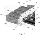
- Fig. 7 is a schematic view for describing an area to be filled with a sealant for waterproofing in the first surface 106c of the fixing member 106.
- the sealant may be injected from above the portion 107a between the edges 107. This makes it possible to more reliably fill the second groove 106b, the gap portion between the heat transport member 104 and the through hole 106a, and the portion 107a between the edges 107, with the sealant.
- Fig. 8 is a schematic view for describing a waterproof structure of a heat dissipation structure 501 according to the comparative example.
- the heat dissipation structure 501 includes a heat generation part 502, an internal heat dissipation part 503, a heat transport member 504, an external heat dissipation part 505, and a fixing member 506.
- the heat generation part 502 is provided inside a housing 508.
- the internal heat dissipation part 503 is disposed in contact with the heat generation part 502, inside the housing 508, and receives heat from the heat generation part 502.
- the heat transport member 504 has a bar shape and protrudes from inside the housing 508 to outside the housing 508 so as to transport heat from the internal heat dissipation part 503 to outside the housing 508.
- the external heat dissipation part 505 includes a plurality of fins 505a and is provided at a portion of the heat transport member 504 outside the housing 508.
- the fixing member 506 is disposed between the internal heat dissipation part 503 and the external heat dissipation part 505.
- the internal heat dissipation part 503, the heat transport member 504, the external heat dissipation part 505, and the fixing member 506 are built up as an assembly 510 and then attached to the housing 508.
- the fixing member 506 is for fixing the assembly 510 to the housing 508.
- Fig. 9 is a schematic view illustrating a configuration of the assembly 510.
- a part of a portion of the heat transport member 504 inside the housing 508 is fitted in a first groove 503a formed on the surface of the internal heat dissipation part 503.
- a waterproof structure for preventing entering of water into the housing 508 through the heat transport member 504 is essential. Accordingly, a gap portion between the heat transport member 504 and a through hole 506a and a gap between the heat transport member 504 and the first groove 503a need to be filled with a sealant.
- Fig. 10 is a cross-sectional view taken along line x-x of Fig. 9 .
- a cream solder is disposed in an interval S1 between the first groove 503a formed in the internal heat dissipation part 503 and the heat transport member 504, and the solder is melted in a reflow furnace, so that the internal heat dissipation part 503 and the heat transport member 504 are joined together (reflow step).
- waterproofing is achieved through filling a gap S2 between the heat transport member 504 and the first groove 503a with a sealant.
- a sealing step of filling, with a sealant, the gap portion between the heat transport member 504 and the through hole 506a see Fig.
- the heat dissipation performance of the heat transport member 504 becomes highest.
- the sealant needs to be injected from the external heat dissipation part 505 side.
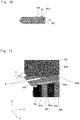
- Fig. 11 is a schematic view for describing the sealing step.
- a substantial distance W1 between the external heat dissipation part 505 and the fixing member 506 (about 10 to 20 mm) as illustrated in Fig. 11 .
- This is for the tip of the nozzle P for injecting the sealant to reach the gap between the heat transport member 504 and the through hole 506a of the fixing member 506.
- a problem is that provision of the substantial distance between the external heat dissipation part 505 and the fixing member 506 for manufacturing reason creates a wasted space and leads to an increase in the device size.
- the second groove extending from the through hole toward the area not covered with the external heat dissipation part is formed in the fixing member.
- the second groove and the gap portion between the heat transport member and the through hole are filled with the sealant. Furthermore, the sealant leaks out from the gap portion between the heat transport member and the through hole to the internal heat dissipation part side in the fixing member, and the portion between the edges vertically disposed on both sides of the heat transport member is also filled with the sealant. Furthermore, the gap between the heat transport member and the first groove is also filled with the sealant. This can satisfactorily suppress entering of water into the housing through the heat transport member in the case where the heat dissipation structure is used for a device to be installed outdoors.
- the heat dissipation structures according to the first and second example embodiments can be satisfactorily used.
- a heat pipe enhances heat dissipation efficiency and thus needs to be disposed so that the heat input portion is on the lower side and the heat dissipation portion is on the upper side.
- the heat dissipation structure needs to be disposed so that the internal heat dissipation part whose heat is input to the heat pipe is on the lower side and the external heat dissipation part for dissipating heat of the heat pipe is on the upper side.
- the fixing member In the case where the heat dissipation structure is thus disposed, the fixing member is located on the upper side of the housing, and thus, when the heat dissipation structure is installed outdoors, rainwater falls directly on the fixing member. Accordingly, the gap portion between the heat transport member and the through hole in the fixing member needs to be more reliably waterproofed.
- the gap portion between the heat transport member and the through hole can be reliably filled with a sealant via the second groove. Furthermore, in the heat dissipation structures according to the first and second example embodiments, no wasted space needs to be provided between the fixing member and the external heat dissipation part.
- the heat dissipation structures according to the first and second example embodiments in the case where a heat pipe is employed as the heat transport member, can satisfactorily suppress entering of water into the housing through the heat transport member and can improve the heat dissipation capacity with respect to the installation space.
- the heat dissipation structure employing the heat pipe is advantageous in that the heat dissipation structure can be downsized, as compared with a heat dissipation structure with a configuration in which refrigerant or water is circulated inside a tube such as a copper tube.
- a wireless communication device to be installed outdoors is often limited in installation space and thus required to be further downsized. Accordingly, a heat dissipation structure to be used for a wireless communication device is preferred to employ a heat pipe as the heat transport member.
- the heat dissipation structures according to the first and second example embodiments can satisfactorily suppress entering of water into the housing through the heat transport member and can improve the heat dissipation capacity with respect to the installation space.
- the present invention is not limited to the above example embodiments and may be changed as appropriate without departing from the gist of the present invention. Furthermore, the plurality of examples described above can be combined with each other as appropriate and implemented.
Landscapes
- Engineering & Computer Science (AREA)
- Microelectronics & Electronic Packaging (AREA)
- Physics & Mathematics (AREA)
- Thermal Sciences (AREA)
- Life Sciences & Earth Sciences (AREA)
- Sustainable Development (AREA)
- Mechanical Engineering (AREA)
- General Engineering & Computer Science (AREA)
- Cooling Or The Like Of Electrical Apparatus (AREA)
- Casings For Electric Apparatus (AREA)
Abstract
Description
- The present invention relates to a heat dissipation structure.
- There has been known a heat dissipation structure for dissipating heat of a heat generation part inside a housing of an electronic device or the like.
Patent Literature 1 discloses a configuration of a heat dissipation structure including a heat generation part disposed inside a housing, an air passage which is disposed outside the housing and through which air flows, and a bar-shaped heat transport member such as a heat pipe which connects the heat generation part and the air passage. Furthermore,Patent Literature 1 discloses a configuration in which a plurality of fins is disposed side by side at a portion of the heat transport member located in the air passage, along the extending direction of the heat transport member. - Patent Literature 1:
Japanese Unexamined Patent Application Publication No. 2008-165699 - In the case where a configuration of a heat dissipation structure in which, as in
Patent Literature 1, the inside and outside of a housing are connected by a heat transport member is used for a device to be installed outdoors, waterproofing of an area where the bar-shaped heat transport member is protruded from inside to outside the housing is indispensable.Patent Literature 1 has no description about the use of the disclosed heat dissipation structure for an outdoor device and accordingly also has no description about a waterproof structure of an area where the bar-shaped heat transport member is protruded from inside to outside the housing. - In view of the above-described problem, an object of the present disclosure is to provide a heat dissipation structure which can, in the case where a configuration in which the inside and outside of a housing are connected by a heat transport member to dissipate heat inside the housing to outside is used for a device to be installed outdoors, suppress entering of water into the housing through the heat transport member.
- A heat dissipation structure according to a first aspect of the present invention includes a heat generation part provided inside a housing; an internal heat dissipation part provided inside the housing for receiving heat from the heat generation part; a heat transport member having a bar shape and protruding from inside the housing to outside the housing, in which a part of a portion inside the housing is fitted in a first groove formed on a surface of the internal heat dissipation part, so as to transport heat from the internal heat dissipation part to outside the housing; an external heat dissipation part including a plurality of fins disposed side by side at a part of a portion of the heat transport member outside the housing; and a fixing member disposed between the internal heat dissipation part and the external heat dissipation part and having a through hole for passage of the heat transport member, in which a first surface facing the internal heat dissipation part is in contact with the internal heat dissipation part and a second surface facing the external heat dissipation part is in contact with the external heat dissipation part, wherein a second groove extending from the through hole toward an area not covered with the external heat dissipation part is formed in the second surface, and a gap portion between the heat transport member and the through hole and the second groove are filled with a sealant for waterproofing.
- In the case where the configuration in which the inside and outside of the housing are connected by the heat transport member to dissipate heat inside the housing to outside is used for a device to be installed outdoors, the present invention can suppress entering of water into the housing through the heat transport member.
-
- [
Fig. 1 ] is a schematic view for describing a structure of a heat dissipation structure according to a first example embodiment. - [
Fig. 2 ] is a schematic view for describing a structure of a heat dissipation structure according to a second example embodiment. - [
Fig. 3 ] is a view of an assembly of the heat dissipation structure according to the second example embodiment as viewed from a direction of arrow B illustrated inFig. 2 . - [
Fig. 4 ] is an enlarged view of the heat dissipation structure according to the second example embodiment in the vicinity of a heat transport member in a first surface of a fixing member. - [
Fig. 5 ] is an enlarged view of the vicinity of a through hole in a second surface of the fixing member. - [
Fig. 6 ] is a schematic view for describing an area to be filled with a sealant for waterproofing in the second surface of the fixing member. - [
Fig. 7 ] is a schematic view for describing an area to be filled with a sealant for waterproofing in the first surface of the fixing member. - [
Fig. 8 ] is a schematic view for describing a waterproof structure of a heat dissipation structure according to a comparative example. - [
Fig. 9 ] is a schematic view illustrating a configuration of an assembly of the heat dissipation structure according to the comparative example. - [
Fig. 10 ] is a cross-sectional view taken along line x-x ofFig. 9 . - [
Fig. 11 ] is a schematic view for describing a sealing step of the heat dissipation structure according to the comparative example. - Hereinafter, example embodiments of the present invention will be described with reference to the drawings. For clarification of the description, omission and simplification are made as appropriate in the following description and the drawings. In the drawings, the same elements are denoted by the same reference signs, and repetitive description thereof is omitted as necessary. The right-handed XYZ-coordinate system illustrated in each of the drawings is for convenience to describe the positional relationship of the elements.
- Hereinafter, a first example embodiment will be described. A heat dissipation structure according to the first example embodiment is suitable for a device to be installed outdoors.
-
Fig. 1 is a schematic view for describing a structure of aheat dissipation structure 1 according to the first example embodiment. As illustrated inFig. 1 , theheat dissipation structure 1 includes aheat generation part 2, an internalheat dissipation part 3, aheat transport member 4, an externalheat dissipation part 5, and afixing member 6. - The
heat generation part 2 is provided inside ahousing 8. The internalheat dissipation part 3 is provided inside thehousing 8 and receives heat from theheat generation part 2. Theheat transport member 4 has a bar shape and protrudes from inside thehousing 8 to outside thehousing 8. Furthermore, a part of a portion of theheat transport member 4 inside thehousing 8 is fitted in afirst groove 3a formed on the surface of the internalheat dissipation part 3, so as to transport heat from the internalheat dissipation part 3 to outside thehousing 8. The externalheat dissipation part 5 includes a plurality offins 5a disposed side by side at a part of a portion of theheat transport member 4 outside thehousing 8. Thefixing member 6 is disposed between the internalheat dissipation part 3 and the externalheat dissipation part 5 and has a throughhole 6a for passage of theheat transport member 4. Furthermore, in thefixing member 6, afirst surface 6c facing the internalheat dissipation part 3 is in contact with the internalheat dissipation part 3, and asecond surface 6d facing the externalheat dissipation part 5 is in contact with the externalheat dissipation part 5. - A
second groove 6b extending from the throughhole 6a toward an area not covered with the externalheat dissipation part 5 is formed in thesecond surface 6d. Here, the area not covered with the externalheat dissipation part 5 in thesecond groove 6b corresponds to a portion in a region surrounded by broken line A. Furthermore, a gap portion between theheat transport member 4 and the throughhole 6a and thesecond groove 6b are filled with a sealant for waterproofing. This can suppress entering of water into thehousing 8 through theheat transport member 4 in the case where theheat dissipation structure 1 is used for a device to be installed outdoors. - Hereinafter, a second example embodiment will be described.
- A heat dissipation structure according to the second example embodiment is suitable for an electronic device to be installed outdoors, for example, a wireless communication device such as an antenna.
-
Fig. 2 is an exploded perspective view for describing a structure of aheat dissipation structure 101 according to the second example embodiment. As illustrated inFig. 2 , theheat dissipation structure 101 includes aheat generation part 102, an internalheat dissipation part 103, aheat transport member 104, an externalheat dissipation part 105, and afixing member 106. The internalheat dissipation part 103, theheat transport member 104, the externalheat dissipation part 105, and thefixing member 106 are built up as anassembly 110 and then attached to ahousing 108. Accordingly,Fig. 2 depicts a state where theassembly 110 is separated from thehousing 108. - The
heat generation part 102 is provided inside thehousing 108. Theheat generation part 102 is, for example, an electronic substrate. The internalheat dissipation part 103 is disposed in contact with theheat generation part 102, inside thehousing 108, and receives heat from theheat generation part 102. Theheat transport member 104 has a bar shape and protrudes from inside thehousing 108 to outside thehousing 108 so as to transport heat from the internalheat dissipation part 103 to outside thehousing 108. - The
heat transport member 104 is, for example, a heat pipe. The heat pipe is a typical one for transporting heat by a phase change (evaporation and condensation) of a small amount of working liquid enclosed in a pipe-shaped container. The typical heat pipe is characterized by having an extremely high thermal conductivity (5000 to 30000 W/m·K), requiring no external power to operate, having a high thermal responsiveness, and having no movable part. Theheat transport member 104 is not limited to the heat pipe and may be a copper tube for internally circulating refrigerant or water, a bar formed of a material such as an alloy having a good thermal conductivity, or the like. The number of theheat transport members 104 is optimized by a heat generation amount of a device to be cooled or a surrounding environment. - The external
heat dissipation part 105 includes a plurality of fins and is provided at a portion of theheat transport member 104 outside thehousing 108. The fixingmember 106 is disposed between the internalheat dissipation part 103 and the externalheat dissipation part 105 for fixing theassembly 110 to thehousing 108. The internalheat dissipation part 103 of theassembly 110 is inserted into anopening 112 formed in thehousing 108, and thehousing 108 and the fixingmember 106 are fastened together by a screw, so that theassembly 110 can be fixed to thehousing 108. A peripheral portion of theopening 112 in thehousing 108 is provided with apacking part 111. Thus, thehousing 108 and the fixingmember 106 contact each other via thepacking part 111. This makes it possible to secure waterproofness and weather resistance. -
Fig. 3 is a view of theassembly 110 as viewed from the direction of arrow B illustrated inFig. 2 . As illustrated inFig. 3 , a part of a portion of theheat transport member 104 inside thehousing 108 is fitted in afirst groove 103a formed on the surface of the internalheat dissipation part 103. Fixing of the internalheat dissipation part 103 and theheat transport member 104 is performed by using, for example, solder. Specifically, the internalheat dissipation part 103 and theheat transport member 104 are put in a reflow furnace, in a state where a cream solder is disposed between theheat transport member 104 and thefirst groove 103a. Then, it is heated in the reflow furnace to melt the cream solder, so that theheat transport member 104 and the internalheat dissipation part 103 are joined together. - The external
heat dissipation part 105 includes a plurality offins 105a disposed side by side in the longitudinal direction of theheat transport member 104. The material of thefins 105a, which is typically aluminum, may be copper. Fixing of thefins 105a and theheat transport member 104 is performed by using solder, caulking, brazing, or the like. - A
first surface 106c of the fixingmember 106 which faces the internalheat dissipation part 103 is in contact with the internalheat dissipation part 103. Furthermore, asecond surface 106d of the fixingmember 106 which faces the externalheat dissipation part 105 is in contact with the externalheat dissipation part 105. A plurality ofscrew insertion holes 106e for screwing the fixingmember 106 to thehousing 108 is formed in the fixingmember 106. -
Fig. 4 is an enlarged view of the vicinity of theheat transport member 104 in thefirst surface 106c of the fixingmember 106. As illustrated inFig. 4 , a throughhole 106a for passage of theheat transport member 104 is formed in the fixingmember 106. As a matter of course, the diameter of the throughhole 106a is larger than the diameter of theheat transport member 104. In other words, when theheat transport member 104 is passed through the throughhole 106a, a gap is generated between the throughhole 106a and theheat transport member 104.Edges 107 are vertically disposed on both sides of theheat transport member 104, in the vicinity of the fixingmember 106 in thefirst groove 103a formed in the internalheat dissipation part 103. -
Fig. 5 is an enlarged view of the vicinity of the throughhole 106a in thesecond surface 106d of the fixingmember 106. For convenience of the description, inFig. 5 , the upper view is a view in which the externalheat dissipation part 105 is depicted, and the lower view is a view in which the externalheat dissipation part 105 is not depicted. As illustrated inFig. 5 , asecond groove 106b extending from the throughhole 106a toward an area not covered with the externalheat dissipation part 105 is formed in thesecond surface 106d. Here, the area not covered with the externalheat dissipation part 105 in thesecond groove 106b corresponds to a portion in a region surrounded by broken line C. -
Fig. 6 is a schematic view for describing an area to be filled with a sealant for waterproofing in thesecond surface 106d of the fixingmember 106. For convenience of the description, inFig. 6 , the upper view is a view in which the externalheat dissipation part 105 is depicted, and the lower view is a view in which the externalheat dissipation part 105 is not depicted. As illustrated in the upper view ofFig. 6 , from the area not covered with the externalheat dissipation part 105 in thesecond groove 106b in the region surrounded by broken line C, the sealant is injected by a nozzle P from a direction of arrow D. Thus, as illustrated in the lower view ofFig. 6 , thesecond groove 106b and a gap portion between theheat transport member 104 and the throughhole 106a are filled with the sealant. The sealant contains, for example, silicone or epoxy resin as its main component. -
Fig. 7 is a schematic view for describing an area to be filled with a sealant for waterproofing in thefirst surface 106c of the fixingmember 106. Once the sealant is injected from the nozzle P illustrated inFig. 6 , the sealant leaks out from the gap portion between theheat transport member 104 and the throughhole 106a to the second surface 10d of the fixingmember 106, and aportion 107a between theedges 107 vertically disposed on both sides of theheat transport member 104 is also filled with the sealant as illustrated inFig. 7 . Furthermore, a gap between theheat transport member 104 and thefirst groove 103a is also filled with the sealant. This can satisfactorily suppress entering of water into thehousing 108 through theheat transport member 104 in the case where theheat dissipation structure 101 is used for a device to be installed outdoors. In addition to injection of the sealant from the area not covered with the externalheat dissipation part 105 in thesecond groove 106b illustrated inFig. 6 , the sealant may be injected from above theportion 107a between theedges 107. This makes it possible to more reliably fill thesecond groove 106b, the gap portion between theheat transport member 104 and the throughhole 106a, and theportion 107a between theedges 107, with the sealant. - Next, problems with a waterproof structure of a heat dissipation structure according to a comparative example will be described.
Fig. 8 is a schematic view for describing a waterproof structure of aheat dissipation structure 501 according to the comparative example. As illustrated inFig. 8 , theheat dissipation structure 501 includes aheat generation part 502, an internalheat dissipation part 503, aheat transport member 504, an externalheat dissipation part 505, and a fixingmember 506. - The
heat generation part 502 is provided inside ahousing 508. The internalheat dissipation part 503 is disposed in contact with theheat generation part 502, inside thehousing 508, and receives heat from theheat generation part 502. Theheat transport member 504 has a bar shape and protrudes from inside thehousing 508 to outside thehousing 508 so as to transport heat from the internalheat dissipation part 503 to outside thehousing 508. The externalheat dissipation part 505 includes a plurality offins 505a and is provided at a portion of theheat transport member 504 outside thehousing 508. The fixingmember 506 is disposed between the internalheat dissipation part 503 and the externalheat dissipation part 505. The internalheat dissipation part 503, theheat transport member 504, the externalheat dissipation part 505, and the fixingmember 506 are built up as anassembly 510 and then attached to thehousing 508. The fixingmember 506 is for fixing theassembly 510 to thehousing 508. -
Fig. 9 is a schematic view illustrating a configuration of theassembly 510. As illustrated inFig. 9 , a part of a portion of theheat transport member 504 inside thehousing 508 is fitted in afirst groove 503a formed on the surface of the internalheat dissipation part 503. In the case where theheat dissipation structure 501 is used for a device to be installed outdoors, a waterproof structure for preventing entering of water into thehousing 508 through theheat transport member 504 is essential. Accordingly, a gap portion between theheat transport member 504 and a throughhole 506a and a gap between theheat transport member 504 and thefirst groove 503a need to be filled with a sealant. -
Fig. 10 is a cross-sectional view taken along line x-x ofFig. 9 . As illustrated inFig. 10 , a cream solder is disposed in an interval S1 between thefirst groove 503a formed in the internalheat dissipation part 503 and theheat transport member 504, and the solder is melted in a reflow furnace, so that the internalheat dissipation part 503 and theheat transport member 504 are joined together (reflow step). As described above, waterproofing is achieved through filling a gap S2 between theheat transport member 504 and thefirst groove 503a with a sealant. A sealing step of filling, with a sealant, the gap portion between theheat transport member 504 and the throughhole 506a (seeFig. 9 ) and the gap between theheat transport member 504 and thefirst groove 503a needs to be performed after the reflow step. This is because if the sealing step is performed before the reflow step, the sealant melts at the time of overheating in the reflow furnace. - In the
heat dissipation structure 501, in the case where theheat generation part 502 is disposed below theheat transport member 504 in the vertical direction and the externalheat dissipation part 505 is disposed above theheat transport member 504 in the vertical direction, the heat dissipation performance of theheat transport member 504 becomes highest. In such disposition, in order to avoid a risk of corrosion of the fixingmember 506 due to accumulation of water in the fixingmember 506, the sealant needs to be injected from the externalheat dissipation part 505 side. -
Fig. 11 is a schematic view for describing the sealing step. In order to fill the gap portion between theheat transport member 504 and the throughhole 506a with the sealant from the externalheat dissipation part 505 side after performing the reflow step, it is necessary to provide a substantial distance W1 between the externalheat dissipation part 505 and the fixing member 506 (about 10 to 20 mm) as illustrated inFig. 11 . This is for the tip of the nozzle P for injecting the sealant to reach the gap between theheat transport member 504 and the throughhole 506a of the fixingmember 506. However, a problem is that provision of the substantial distance between the externalheat dissipation part 505 and the fixingmember 506 for manufacturing reason creates a wasted space and leads to an increase in the device size. - In contrast to the configuration of the comparative example, in the above-described configurations of the heat dissipation structures according to the first and second example embodiments, the second groove extending from the through hole toward the area not covered with the external heat dissipation part is formed in the fixing member. Thus, even in the case where the fixing member and the external heat dissipation part are disposed in contact with each other, the sealant can be injected from the area not covered with the external heat dissipation part in the second groove. Therefore, it is not necessary to provide a space for inserting the nozzle for injecting the sealant, between the fixing member and the external heat dissipation part, so that no wasted space is created and the device size is not increased. In other words, the heat dissipation capacity with respect to the installation space can be improved.
- Furthermore, in the configurations of the heat dissipation structures according to the first and second example embodiments, once the sealant is dropped from the area not covered with the external heat dissipation part in the second groove, the second groove and the gap portion between the heat transport member and the through hole are filled with the sealant. Furthermore, the sealant leaks out from the gap portion between the heat transport member and the through hole to the internal heat dissipation part side in the fixing member, and the portion between the edges vertically disposed on both sides of the heat transport member is also filled with the sealant. Furthermore, the gap between the heat transport member and the first groove is also filled with the sealant. This can satisfactorily suppress entering of water into the housing through the heat transport member in the case where the heat dissipation structure is used for a device to be installed outdoors.
- In particular, in the case where a configuration of a heat dissipation structure for dissipating heat inside the housing to outside via the heat transport member employs a heat pipe as the heat transport member, the heat dissipation structures according to the first and second example embodiments can be satisfactorily used. A heat pipe enhances heat dissipation efficiency and thus needs to be disposed so that the heat input portion is on the lower side and the heat dissipation portion is on the upper side. In other words, the heat dissipation structure needs to be disposed so that the internal heat dissipation part whose heat is input to the heat pipe is on the lower side and the external heat dissipation part for dissipating heat of the heat pipe is on the upper side. In the case where the heat dissipation structure is thus disposed, the fixing member is located on the upper side of the housing, and thus, when the heat dissipation structure is installed outdoors, rainwater falls directly on the fixing member. Accordingly, the gap portion between the heat transport member and the through hole in the fixing member needs to be more reliably waterproofed. In the heat dissipation structures according to the first and second example embodiments, the gap portion between the heat transport member and the through hole can be reliably filled with a sealant via the second groove. Furthermore, in the heat dissipation structures according to the first and second example embodiments, no wasted space needs to be provided between the fixing member and the external heat dissipation part. Therefore, the heat dissipation structures according to the first and second example embodiments, in the case where a heat pipe is employed as the heat transport member, can satisfactorily suppress entering of water into the housing through the heat transport member and can improve the heat dissipation capacity with respect to the installation space.
- The heat dissipation structure employing the heat pipe is advantageous in that the heat dissipation structure can be downsized, as compared with a heat dissipation structure with a configuration in which refrigerant or water is circulated inside a tube such as a copper tube. A wireless communication device to be installed outdoors is often limited in installation space and thus required to be further downsized. Accordingly, a heat dissipation structure to be used for a wireless communication device is preferred to employ a heat pipe as the heat transport member. Therefore, the heat dissipation structures according to the first and second example embodiments, even in the case of the use for a wireless communication device, can satisfactorily suppress entering of water into the housing through the heat transport member and can improve the heat dissipation capacity with respect to the installation space.
- The present invention is not limited to the above example embodiments and may be changed as appropriate without departing from the gist of the present invention. Furthermore, the plurality of examples described above can be combined with each other as appropriate and implemented.
- The present invention has been described above with reference to the example embodiments, but the present invention is not limited to the above. Various changes which can be understood by those skilled in the art can be made to the configurations and details of the present invention within the scope of the invention.
- This application claims priority based on
Japanese Patent Application No. 2018-213184 filed on November 13, 2018 -
- 1, 101 heat dissipation structure
- 2, 102 heat generation part
- 3, 103 internal heat dissipation part
- 3a, 103a first groove
- 4, 104 heat transport member
- 5, 105 external heat dissipation part
- 5a, 105a fin
- 6, 106 fixing member
- 6a, 106a through hole
- 6b, 106b second groove
- 6c, 106c first surface
- 6d, 106d second surface
- 8, 108 housing
- 106e screw insertion hole
- 107 edge
- 110 assembly
- 111 packing part
- 112 opening
Claims (5)
- A heat dissipation structure comprising:heat generation means provided inside a housing;internal heat dissipation means provided inside the housing for receiving heat from the heat generation means;a heat transport member comprising a bar shape and protruding from inside the housing to outside the housing, a part of a portion of the heat transport member inside the housing being fitted in a first groove formed on a surface of the internal heat dissipation means, so as to transport heat from the internal heat dissipation means to outside the housing;external heat dissipation means comprising a plurality of fins disposed side by side at a part of a portion of the heat transport member outside the housing; anda fixing member disposed between the internal heat dissipation means and the external heat dissipation means and comprising a through hole for passage of the heat transport member, the fixing member comprising a first surface facing the internal heat dissipation means, and a second surface facing the external heat dissipation means, the first surface being in contact with the internal heat dissipation means, the second surface being in contact with the external heat dissipation means, whereina second groove extending from the through hole toward an area not covered with the external heat dissipation means is formed in the second surface, anda gap portion between the heat transport member and the through hole and the second groove are filled with a sealant for waterproofing.
- The heat dissipation structure according to Claim 1, wherein
edges are vertically disposed on both sides of the heat transport member, in a vicinity of the fixing member in the first groove, and
a portion between the edges vertically disposed on both sides of the heat transport member is filled with a sealant for waterproofing. - The heat dissipation structure according to Claim 1 or 2, wherein the heat transport member is fixed to the internal heat dissipation means by solder.
- The heat dissipation structure according to any one of Claims 1 to 3, wherein the heat transport member is a heat pipe.
- The heat dissipation structure according to any one of Claims 1 to 4, wherein the housing is a housing for a wireless communication device to be installed outdoors.
Applications Claiming Priority (2)
| Application Number | Priority Date | Filing Date | Title |
|---|---|---|---|
| JP2018213184A JP6733918B2 (en) | 2018-11-13 | 2018-11-13 | Heat dissipation structure |
| PCT/JP2019/038028 WO2020100447A1 (en) | 2018-11-13 | 2019-09-26 | Heat dissipation structure |
Publications (4)
| Publication Number | Publication Date |
|---|---|
| EP3863389A1 true EP3863389A1 (en) | 2021-08-11 |
| EP3863389A4 EP3863389A4 (en) | 2022-06-29 |
| EP3863389B1 EP3863389B1 (en) | 2024-07-17 |
| EP3863389C0 EP3863389C0 (en) | 2024-07-17 |
Family
ID=70731340
Family Applications (1)
| Application Number | Title | Priority Date | Filing Date |
|---|---|---|---|
| EP19885063.8A Active EP3863389B1 (en) | 2018-11-13 | 2019-09-26 | Heat dissipation structure |
Country Status (5)
| Country | Link |
|---|---|
| US (1) | US11979993B2 (en) |
| EP (1) | EP3863389B1 (en) |
| JP (1) | JP6733918B2 (en) |
| CN (1) | CN112997595B (en) |
| WO (1) | WO2020100447A1 (en) |
Families Citing this family (1)
| Publication number | Priority date | Publication date | Assignee | Title |
|---|---|---|---|---|
| CN117438387A (en) * | 2022-07-20 | 2024-01-23 | 陈威霖 | integrated circuit packaging |
Family Cites Families (17)
| Publication number | Priority date | Publication date | Assignee | Title |
|---|---|---|---|---|
| DE2920577C2 (en) * | 1979-05-21 | 1982-12-23 | Gifa Planungsgesellschaft für Industrie- und Forschungsanlagen mbH, 8000 München | Heat exchanger with at least one heat pipe for installation in a bulkhead |
| JPS6134744U (en) * | 1984-07-31 | 1986-03-03 | 株式会社日立ホームテック | Cooling equipment for electronic equipment |
| JPH035079U (en) * | 1989-06-02 | 1991-01-18 | ||
| JPH04123463A (en) | 1990-09-14 | 1992-04-23 | Furukawa Electric Co Ltd:The | Heat pipe type semiconductor cooler |
| JP3337789B2 (en) * | 1993-10-15 | 2002-10-21 | 古河電気工業株式会社 | Heat pipe type cooler |
| JPH11233963A (en) * | 1998-02-12 | 1999-08-27 | Omron Corp | Seal structure for electrical equipment |
| CN2699477Y (en) * | 2004-05-17 | 2005-05-11 | 华音电器股份有限公司 | Heat-pipe radiator construction |
| JP4256310B2 (en) * | 2004-06-30 | 2009-04-22 | 株式会社東芝 | Electronics |
| CN200980219Y (en) * | 2006-11-29 | 2007-11-21 | 陈世明 | Heat pipe radiator base dense structure |
| JP2008165699A (en) | 2007-01-05 | 2008-07-17 | Sumitomo Electric Ind Ltd | Heat dissipation device and device with heat dissipation device |
| US7942194B2 (en) | 2007-04-10 | 2011-05-17 | Fujikura Ltd. | Heat sink |
| JP2009252646A (en) * | 2008-04-09 | 2009-10-29 | Calsonic Kansei Corp | Cooling device of heat generator |
| US8559173B2 (en) * | 2010-03-15 | 2013-10-15 | Panasonic Corporation | Electronic apparatus provided with cooling structure |
| TWM426756U (en) * | 2011-08-04 | 2012-04-11 | Cooler Master Co Ltd | Heat sink with the heat pipe protection mechanism |
| US20150354902A1 (en) * | 2013-01-10 | 2015-12-10 | Woods Hole Oceanographic Institution | Thermal transfer system |
| JP6248292B2 (en) * | 2013-03-29 | 2017-12-20 | アール・ビー・コントロールズ株式会社 | Electronic equipment |
| JP2018021318A (en) | 2016-08-01 | 2018-02-08 | 株式会社城南製作所 | Vehicle lock device |
-
2018
- 2018-11-13 JP JP2018213184A patent/JP6733918B2/en active Active
-
2019
- 2019-09-26 WO PCT/JP2019/038028 patent/WO2020100447A1/en not_active Ceased
- 2019-09-26 EP EP19885063.8A patent/EP3863389B1/en active Active
- 2019-09-26 US US17/292,756 patent/US11979993B2/en active Active
- 2019-09-26 CN CN201980074246.4A patent/CN112997595B/en active Active
Also Published As
| Publication number | Publication date |
|---|---|
| EP3863389B1 (en) | 2024-07-17 |
| US20210400825A1 (en) | 2021-12-23 |
| WO2020100447A1 (en) | 2020-05-22 |
| US11979993B2 (en) | 2024-05-07 |
| EP3863389A4 (en) | 2022-06-29 |
| CN112997595A (en) | 2021-06-18 |
| EP3863389C0 (en) | 2024-07-17 |
| JP2020080381A (en) | 2020-05-28 |
| JP6733918B2 (en) | 2020-08-05 |
| CN112997595B (en) | 2024-02-13 |
Similar Documents
| Publication | Publication Date | Title |
|---|---|---|
| EP1841305B1 (en) | Electronic control device | |
| US8471380B2 (en) | Fluid cooled encapsulated microelectronic package | |
| US7165603B2 (en) | Tower type heat sink | |
| JP5955251B2 (en) | Power semiconductor module | |
| EP3930168A1 (en) | Electric power conversion device | |
| EP3962254A1 (en) | Heat dissipation structure | |
| CN102510709A (en) | Immersion cooling electronic equipment | |
| US9478477B2 (en) | Semiconductor device | |
| EP3686540B1 (en) | Heat sink | |
| EP3863389B1 (en) | Heat dissipation structure | |
| JP5529187B2 (en) | Semiconductor package | |
| CN103858226A (en) | Diode unit module | |
| US11432440B2 (en) | Power conversion apparatus | |
| US20250198709A1 (en) | Heat sink | |
| KR102574376B1 (en) | Direct cooling type power module | |
| US11195650B2 (en) | Reactor | |
| JP7708445B2 (en) | heat dissipation structure | |
| CN207869062U (en) | low temperature photovoltaic junction box | |
| JP7199574B2 (en) | Chillers and power converters | |
| CN210723042U (en) | Packaging structure of surface mount diode | |
| JP5066897B2 (en) | Electrical component unit | |
| JP2017212344A (en) | Semiconductor device | |
| CN108173515A (en) | low temperature photovoltaic junction box | |
| CN121127965A (en) | Adapters and semiconductor cooling devices | |
| JP2008130751A (en) | Semiconductor device |
Legal Events
| Date | Code | Title | Description |
|---|---|---|---|
| STAA | Information on the status of an ep patent application or granted ep patent |
Free format text: STATUS: THE INTERNATIONAL PUBLICATION HAS BEEN MADE |
|
| PUAI | Public reference made under article 153(3) epc to a published international application that has entered the european phase |
Free format text: ORIGINAL CODE: 0009012 |
|
| STAA | Information on the status of an ep patent application or granted ep patent |
Free format text: STATUS: REQUEST FOR EXAMINATION WAS MADE |
|
| 17P | Request for examination filed |
Effective date: 20210506 |
|
| AK | Designated contracting states |
Kind code of ref document: A1 Designated state(s): AL AT BE BG CH CY CZ DE DK EE ES FI FR GB GR HR HU IE IS IT LI LT LU LV MC MK MT NL NO PL PT RO RS SE SI SK SM TR |
|
| DAV | Request for validation of the european patent (deleted) | ||
| DAX | Request for extension of the european patent (deleted) | ||
| A4 | Supplementary search report drawn up and despatched |
Effective date: 20220601 |
|
| RIC1 | Information provided on ipc code assigned before grant |
Ipc: F28D 15/02 20060101ALI20220525BHEP Ipc: H05K 5/06 20060101ALI20220525BHEP Ipc: H05K 7/20 20060101AFI20220525BHEP |
|
| GRAP | Despatch of communication of intention to grant a patent |
Free format text: ORIGINAL CODE: EPIDOSNIGR1 |
|
| STAA | Information on the status of an ep patent application or granted ep patent |
Free format text: STATUS: GRANT OF PATENT IS INTENDED |
|
| INTG | Intention to grant announced |
Effective date: 20240312 |
|
| GRAS | Grant fee paid |
Free format text: ORIGINAL CODE: EPIDOSNIGR3 |
|
| GRAA | (expected) grant |
Free format text: ORIGINAL CODE: 0009210 |
|
| STAA | Information on the status of an ep patent application or granted ep patent |
Free format text: STATUS: THE PATENT HAS BEEN GRANTED |
|
| AK | Designated contracting states |
Kind code of ref document: B1 Designated state(s): AL AT BE BG CH CY CZ DE DK EE ES FI FR GB GR HR HU IE IS IT LI LT LU LV MC MK MT NL NO PL PT RO RS SE SI SK SM TR |
|
| REG | Reference to a national code |
Ref country code: CH Ref legal event code: EP |
|
| REG | Reference to a national code |
Ref country code: DE Ref legal event code: R096 Ref document number: 602019055519 Country of ref document: DE |
|
| REG | Reference to a national code |
Ref country code: IE Ref legal event code: FG4D |
|
| U01 | Request for unitary effect filed |
Effective date: 20240717 |
|
| U07 | Unitary effect registered |
Designated state(s): AT BE BG DE DK EE FI FR IT LT LU LV MT NL PT SE SI Effective date: 20240730 |
|
| U20 | Renewal fee for the european patent with unitary effect paid |
Year of fee payment: 6 Effective date: 20240925 |
|
| PG25 | Lapsed in a contracting state [announced via postgrant information from national office to epo] |
Ref country code: NO Free format text: LAPSE BECAUSE OF FAILURE TO SUBMIT A TRANSLATION OF THE DESCRIPTION OR TO PAY THE FEE WITHIN THE PRESCRIBED TIME-LIMIT Effective date: 20241017 |
|
| PG25 | Lapsed in a contracting state [announced via postgrant information from national office to epo] |
Ref country code: GR Free format text: LAPSE BECAUSE OF FAILURE TO SUBMIT A TRANSLATION OF THE DESCRIPTION OR TO PAY THE FEE WITHIN THE PRESCRIBED TIME-LIMIT Effective date: 20241018 Ref country code: PL Free format text: LAPSE BECAUSE OF FAILURE TO SUBMIT A TRANSLATION OF THE DESCRIPTION OR TO PAY THE FEE WITHIN THE PRESCRIBED TIME-LIMIT Effective date: 20240717 |
|
| PG25 | Lapsed in a contracting state [announced via postgrant information from national office to epo] |
Ref country code: IS Free format text: LAPSE BECAUSE OF FAILURE TO SUBMIT A TRANSLATION OF THE DESCRIPTION OR TO PAY THE FEE WITHIN THE PRESCRIBED TIME-LIMIT Effective date: 20241117 |
|
| PG25 | Lapsed in a contracting state [announced via postgrant information from national office to epo] |
Ref country code: HR Free format text: LAPSE BECAUSE OF FAILURE TO SUBMIT A TRANSLATION OF THE DESCRIPTION OR TO PAY THE FEE WITHIN THE PRESCRIBED TIME-LIMIT Effective date: 20240717 |
|
| PG25 | Lapsed in a contracting state [announced via postgrant information from national office to epo] |
Ref country code: RS Free format text: LAPSE BECAUSE OF FAILURE TO SUBMIT A TRANSLATION OF THE DESCRIPTION OR TO PAY THE FEE WITHIN THE PRESCRIBED TIME-LIMIT Effective date: 20241017 Ref country code: ES Free format text: LAPSE BECAUSE OF FAILURE TO SUBMIT A TRANSLATION OF THE DESCRIPTION OR TO PAY THE FEE WITHIN THE PRESCRIBED TIME-LIMIT Effective date: 20240717 |
|
| PG25 | Lapsed in a contracting state [announced via postgrant information from national office to epo] |
Ref country code: RS Free format text: LAPSE BECAUSE OF FAILURE TO SUBMIT A TRANSLATION OF THE DESCRIPTION OR TO PAY THE FEE WITHIN THE PRESCRIBED TIME-LIMIT Effective date: 20241017 Ref country code: PL Free format text: LAPSE BECAUSE OF FAILURE TO SUBMIT A TRANSLATION OF THE DESCRIPTION OR TO PAY THE FEE WITHIN THE PRESCRIBED TIME-LIMIT Effective date: 20240717 Ref country code: NO Free format text: LAPSE BECAUSE OF FAILURE TO SUBMIT A TRANSLATION OF THE DESCRIPTION OR TO PAY THE FEE WITHIN THE PRESCRIBED TIME-LIMIT Effective date: 20241017 Ref country code: IS Free format text: LAPSE BECAUSE OF FAILURE TO SUBMIT A TRANSLATION OF THE DESCRIPTION OR TO PAY THE FEE WITHIN THE PRESCRIBED TIME-LIMIT Effective date: 20241117 Ref country code: HR Free format text: LAPSE BECAUSE OF FAILURE TO SUBMIT A TRANSLATION OF THE DESCRIPTION OR TO PAY THE FEE WITHIN THE PRESCRIBED TIME-LIMIT Effective date: 20240717 Ref country code: GR Free format text: LAPSE BECAUSE OF FAILURE TO SUBMIT A TRANSLATION OF THE DESCRIPTION OR TO PAY THE FEE WITHIN THE PRESCRIBED TIME-LIMIT Effective date: 20241018 Ref country code: ES Free format text: LAPSE BECAUSE OF FAILURE TO SUBMIT A TRANSLATION OF THE DESCRIPTION OR TO PAY THE FEE WITHIN THE PRESCRIBED TIME-LIMIT Effective date: 20240717 |
|
| PG25 | Lapsed in a contracting state [announced via postgrant information from national office to epo] |
Ref country code: SM Free format text: LAPSE BECAUSE OF FAILURE TO SUBMIT A TRANSLATION OF THE DESCRIPTION OR TO PAY THE FEE WITHIN THE PRESCRIBED TIME-LIMIT Effective date: 20240717 |
|
| PG25 | Lapsed in a contracting state [announced via postgrant information from national office to epo] |
Ref country code: MC Free format text: LAPSE BECAUSE OF FAILURE TO SUBMIT A TRANSLATION OF THE DESCRIPTION OR TO PAY THE FEE WITHIN THE PRESCRIBED TIME-LIMIT Effective date: 20240717 |
|
| PG25 | Lapsed in a contracting state [announced via postgrant information from national office to epo] |
Ref country code: CZ Free format text: LAPSE BECAUSE OF FAILURE TO SUBMIT A TRANSLATION OF THE DESCRIPTION OR TO PAY THE FEE WITHIN THE PRESCRIBED TIME-LIMIT Effective date: 20240717 |
|
| PG25 | Lapsed in a contracting state [announced via postgrant information from national office to epo] |
Ref country code: SK Free format text: LAPSE BECAUSE OF FAILURE TO SUBMIT A TRANSLATION OF THE DESCRIPTION OR TO PAY THE FEE WITHIN THE PRESCRIBED TIME-LIMIT Effective date: 20240717 |
|
| REG | Reference to a national code |
Ref country code: CH Ref legal event code: PL |
|
| PLBE | No opposition filed within time limit |
Free format text: ORIGINAL CODE: 0009261 |
|
| STAA | Information on the status of an ep patent application or granted ep patent |
Free format text: STATUS: NO OPPOSITION FILED WITHIN TIME LIMIT |
|
| 26N | No opposition filed |
Effective date: 20250422 |
|
| PG25 | Lapsed in a contracting state [announced via postgrant information from national office to epo] |
Ref country code: CH Free format text: LAPSE BECAUSE OF NON-PAYMENT OF DUE FEES Effective date: 20240930 |
|
| PG25 | Lapsed in a contracting state [announced via postgrant information from national office to epo] |
Ref country code: IE Free format text: LAPSE BECAUSE OF NON-PAYMENT OF DUE FEES Effective date: 20240926 |
|
| PGFP | Annual fee paid to national office [announced via postgrant information from national office to epo] |
Ref country code: GB Payment date: 20250919 Year of fee payment: 7 |
|
| U20 | Renewal fee for the european patent with unitary effect paid |
Year of fee payment: 7 Effective date: 20250924 |
|
| PG25 | Lapsed in a contracting state [announced via postgrant information from national office to epo] |
Ref country code: RO Free format text: LAPSE BECAUSE OF FAILURE TO SUBMIT A TRANSLATION OF THE DESCRIPTION OR TO PAY THE FEE WITHIN THE PRESCRIBED TIME-LIMIT Effective date: 20240717 |
|
| PG25 | Lapsed in a contracting state [announced via postgrant information from national office to epo] |
Ref country code: CY Free format text: LAPSE BECAUSE OF FAILURE TO SUBMIT A TRANSLATION OF THE DESCRIPTION OR TO PAY THE FEE WITHIN THE PRESCRIBED TIME-LIMIT; INVALID AB INITIO Effective date: 20190926 |
|
| PG25 | Lapsed in a contracting state [announced via postgrant information from national office to epo] |
Ref country code: HU Free format text: LAPSE BECAUSE OF FAILURE TO SUBMIT A TRANSLATION OF THE DESCRIPTION OR TO PAY THE FEE WITHIN THE PRESCRIBED TIME-LIMIT; INVALID AB INITIO Effective date: 20190926 |