EP3863036B1 - Appareil de coupure de circuit et système de coupure de circuit - Google Patents
Appareil de coupure de circuit et système de coupure de circuit Download PDFInfo
- Publication number
- EP3863036B1 EP3863036B1 EP19868797.2A EP19868797A EP3863036B1 EP 3863036 B1 EP3863036 B1 EP 3863036B1 EP 19868797 A EP19868797 A EP 19868797A EP 3863036 B1 EP3863036 B1 EP 3863036B1
- Authority
- EP
- European Patent Office
- Prior art keywords
- separable
- separable portion
- terminal
- actuator pin
- interrupter
- Prior art date
- Legal status (The legal status is an assumption and is not a legal conclusion. Google has not performed a legal analysis and makes no representation as to the accuracy of the status listed.)
- Active
Links
- 239000004020 conductor Substances 0.000 claims description 171
- 239000000446 fuel Substances 0.000 claims description 14
- 230000008878 coupling Effects 0.000 claims description 12
- 238000010168 coupling process Methods 0.000 claims description 12
- 238000005859 coupling reaction Methods 0.000 claims description 12
- 238000010292 electrical insulation Methods 0.000 claims description 4
- 239000007789 gas Substances 0.000 description 90
- 238000003825 pressing Methods 0.000 description 42
- 238000010791 quenching Methods 0.000 description 40
- 230000000171 quenching effect Effects 0.000 description 40
- 239000000470 constituent Substances 0.000 description 38
- 239000002245 particle Substances 0.000 description 21
- 230000006870 function Effects 0.000 description 19
- 238000005520 cutting process Methods 0.000 description 17
- 230000002093 peripheral effect Effects 0.000 description 17
- 238000002844 melting Methods 0.000 description 14
- 230000008018 melting Effects 0.000 description 14
- 230000001105 regulatory effect Effects 0.000 description 5
- 239000011347 resin Substances 0.000 description 5
- 229920005989 resin Polymers 0.000 description 5
- UFHFLCQGNIYNRP-UHFFFAOYSA-N Hydrogen Chemical compound [H][H] UFHFLCQGNIYNRP-UHFFFAOYSA-N 0.000 description 4
- 229910045601 alloy Inorganic materials 0.000 description 4
- 239000000956 alloy Substances 0.000 description 4
- 238000005219 brazing Methods 0.000 description 4
- 239000003990 capacitor Substances 0.000 description 4
- 239000001257 hydrogen Substances 0.000 description 4
- 229910052739 hydrogen Inorganic materials 0.000 description 4
- 239000000463 material Substances 0.000 description 4
- RYGMFSIKBFXOCR-UHFFFAOYSA-N Copper Chemical compound [Cu] RYGMFSIKBFXOCR-UHFFFAOYSA-N 0.000 description 3
- 229910052802 copper Inorganic materials 0.000 description 3
- 239000010949 copper Substances 0.000 description 3
- XEEYBQQBJWHFJM-UHFFFAOYSA-N Iron Chemical compound [Fe] XEEYBQQBJWHFJM-UHFFFAOYSA-N 0.000 description 2
- VYPSYNLAJGMNEJ-UHFFFAOYSA-N Silicium dioxide Chemical compound O=[Si]=O VYPSYNLAJGMNEJ-UHFFFAOYSA-N 0.000 description 2
- 230000002159 abnormal effect Effects 0.000 description 2
- 239000002360 explosive Substances 0.000 description 2
- 239000011159 matrix material Substances 0.000 description 2
- JSOGDEOQBIUNTR-UHFFFAOYSA-N 2-(azidomethyl)oxirane Chemical compound [N-]=[N+]=NCC1CO1 JSOGDEOQBIUNTR-UHFFFAOYSA-N 0.000 description 1
- VYZAMTAEIAYCRO-UHFFFAOYSA-N Chromium Chemical compound [Cr] VYZAMTAEIAYCRO-UHFFFAOYSA-N 0.000 description 1
- 239000000020 Nitrocellulose Substances 0.000 description 1
- 239000004677 Nylon Substances 0.000 description 1
- 239000004952 Polyamide Substances 0.000 description 1
- 229910052782 aluminium Inorganic materials 0.000 description 1
- XAGFODPZIPBFFR-UHFFFAOYSA-N aluminium Chemical compound [Al] XAGFODPZIPBFFR-UHFFFAOYSA-N 0.000 description 1
- PNEYBMLMFCGWSK-UHFFFAOYSA-N aluminium oxide Inorganic materials [O-2].[O-2].[O-2].[Al+3].[Al+3] PNEYBMLMFCGWSK-UHFFFAOYSA-N 0.000 description 1
- 150000001540 azides Chemical class 0.000 description 1
- 238000005452 bending Methods 0.000 description 1
- 229910052804 chromium Inorganic materials 0.000 description 1
- 239000011651 chromium Substances 0.000 description 1
- 229910052681 coesite Inorganic materials 0.000 description 1
- 230000006835 compression Effects 0.000 description 1
- 238000007906 compression Methods 0.000 description 1
- 230000001276 controlling effect Effects 0.000 description 1
- 229910052906 cristobalite Inorganic materials 0.000 description 1
- 238000010586 diagram Methods 0.000 description 1
- 230000005611 electricity Effects 0.000 description 1
- 230000004907 flux Effects 0.000 description 1
- 238000009434 installation Methods 0.000 description 1
- 238000009413 insulation Methods 0.000 description 1
- 229910052742 iron Inorganic materials 0.000 description 1
- VTHJTEIRLNZDEV-UHFFFAOYSA-L magnesium dihydroxide Chemical compound [OH-].[OH-].[Mg+2] VTHJTEIRLNZDEV-UHFFFAOYSA-L 0.000 description 1
- 239000000347 magnesium hydroxide Substances 0.000 description 1
- 229910001862 magnesium hydroxide Inorganic materials 0.000 description 1
- 238000004519 manufacturing process Methods 0.000 description 1
- 229910003465 moissanite Inorganic materials 0.000 description 1
- 229910001120 nichrome Inorganic materials 0.000 description 1
- 229920001220 nitrocellulos Polymers 0.000 description 1
- 229920001778 nylon Polymers 0.000 description 1
- 229920002647 polyamide Polymers 0.000 description 1
- 229920006122 polyamide resin Polymers 0.000 description 1
- 229920000642 polymer Polymers 0.000 description 1
- 238000004080 punching Methods 0.000 description 1
- 238000004904 shortening Methods 0.000 description 1
- 229910010271 silicon carbide Inorganic materials 0.000 description 1
- 239000000377 silicon dioxide Substances 0.000 description 1
- 229910052682 stishovite Inorganic materials 0.000 description 1
- 239000000758 substrate Substances 0.000 description 1
- 230000001360 synchronised effect Effects 0.000 description 1
- 229910052905 tridymite Inorganic materials 0.000 description 1
- NFMWFGXCDDYTEG-UHFFFAOYSA-N trimagnesium;diborate Chemical compound [Mg+2].[Mg+2].[Mg+2].[O-]B([O-])[O-].[O-]B([O-])[O-] NFMWFGXCDDYTEG-UHFFFAOYSA-N 0.000 description 1
- WFKWXMTUELFFGS-UHFFFAOYSA-N tungsten Chemical compound [W] WFKWXMTUELFFGS-UHFFFAOYSA-N 0.000 description 1
- 229910052721 tungsten Inorganic materials 0.000 description 1
- 239000010937 tungsten Substances 0.000 description 1
- 238000003466 welding Methods 0.000 description 1
Images


Classifications
-
- H—ELECTRICITY
- H01—ELECTRIC ELEMENTS
- H01H—ELECTRIC SWITCHES; RELAYS; SELECTORS; EMERGENCY PROTECTIVE DEVICES
- H01H39/00—Switching devices actuated by an explosion produced within the device and initiated by an electric current
- H01H39/006—Opening by severing a conductor
-
- H—ELECTRICITY
- H01—ELECTRIC ELEMENTS
- H01H—ELECTRIC SWITCHES; RELAYS; SELECTORS; EMERGENCY PROTECTIVE DEVICES
- H01H1/00—Contacts
- H01H1/12—Contacts characterised by the manner in which co-operating contacts engage
- H01H1/14—Contacts characterised by the manner in which co-operating contacts engage by abutting
- H01H1/20—Bridging contacts
- H01H1/2025—Bridging contacts comprising two-parallel bridges
-
- H—ELECTRICITY
- H01—ELECTRIC ELEMENTS
- H01H—ELECTRIC SWITCHES; RELAYS; SELECTORS; EMERGENCY PROTECTIVE DEVICES
- H01H39/00—Switching devices actuated by an explosion produced within the device and initiated by an electric current
- H01H2039/008—Switching devices actuated by an explosion produced within the device and initiated by an electric current using the switch for a battery cutoff
-
- H—ELECTRICITY
- H01—ELECTRIC ELEMENTS
- H01H—ELECTRIC SWITCHES; RELAYS; SELECTORS; EMERGENCY PROTECTIVE DEVICES
- H01H85/00—Protective devices in which the current flows through a part of fusible material and this current is interrupted by displacement of the fusible material when this current becomes excessive
- H01H85/0039—Means for influencing the rupture process of the fusible element
- H01H85/0047—Heating means
- H01H85/0065—Heat reflective or insulating layer on the fusible element
-
- H—ELECTRICITY
- H01—ELECTRIC ELEMENTS
- H01H—ELECTRIC SWITCHES; RELAYS; SELECTORS; EMERGENCY PROTECTIVE DEVICES
- H01H9/00—Details of switching devices, not covered by groups H01H1/00 - H01H7/00
- H01H9/30—Means for extinguishing or preventing arc between current-carrying parts
-
- H—ELECTRICITY
- H01—ELECTRIC ELEMENTS
- H01H—ELECTRIC SWITCHES; RELAYS; SELECTORS; EMERGENCY PROTECTIVE DEVICES
- H01H9/00—Details of switching devices, not covered by groups H01H1/00 - H01H7/00
- H01H9/30—Means for extinguishing or preventing arc between current-carrying parts
- H01H9/44—Means for extinguishing or preventing arc between current-carrying parts using blow-out magnet
Definitions
- the present disclosure generally relates to an interrupter and an interrupter system, and more particularly relates to an interrupter designed to interrupt an electric circuit by using a gas pressure and an interrupter system including a plurality of such interrupters.
- Patent Literature 1 discloses a known circuit breaker (interrupter).
- the circuit breaker includes at least one electrical conductor designed to be connected to an electric circuit (or electrical path), a housing, a matrix, a punch, and an actuator (actuator pin) that uses a pyrotechnic.
- the pyrotechnic actuator is designed to advance, when ignited, its punch from a first position to a second position. When the punch advances from the first position to the second position, the punch and the matrix break the at least one electrical conductor into at least two separate parts.
- Circuit breakers such as the one disclosed in Patent Literature 1 are sometimes required to improve their electric circuit interrupting capability.
- Patent Literature 1 JP 2017-507469 A
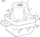
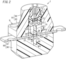
- An interrupter 1 includes a gas producer 7, an electrical conductor 2, and an actuator pin 8 as shown in FIGS. 1 and 2 .
- the interrupter 1 further includes a housing portion 9 (housing) having an internal space SP1.
- the internal space SP1 includes a housing space 98 and a drive space SP10.
- the gas producer 7 contains a fuel 74.
- the fuel 74 is an explosive such as nitrocellulose, lead azide, a black explosive, or a glycidyl azide polymer.
- the gas producer 7 produces a gas by burning the fuel 74.
- the electrical conductor 2 includes: a separable portion 21 forming part of an electric circuit; two terminal portions 22 (continuous portions) connected to the separable portion 21 and forming other parts of the electric circuit; and two boundary portions 23.
- the separable portion 21 is arranged in the internal space SP1 of the housing portion 9.
- One of the two boundary portions 23 couples one of the two terminal portions 22 to the separable portion 21.
- the other of the two boundary portions 23 couples the other of the two terminal portions 22 to the separable portion 21.
- the separable portion 21, the two terminal portions 22, and the two boundary portions 23 form respective parts of a single continuous member.
- the fuel 74 is burned by the gas producer 7, thus producing a gas.
- the actuator pin 8 is driven under the pressure of the gas produced by the gas producer 7. Then, the boundary portions 23, located between the separable portion 21 and the two terminal portions 22, respectively, of the electrical conductor 2 are broken by the actuator pin 8, thus causing the separable portion 21 to be cut off from the two terminal portions 22 and thereby interrupting the electric circuit.
- the housing space 98 houses the separable portion 21 that has been cut off from the two terminal portions 22.
- boundary portions 23 are regarded as portions located between the terminal portions 22 and the separable portion 21.
- each boundary portion 23 between the separable portion 21 and an associated one of the two terminal portions 22 of the electrical conductor 2 will also be regarded as a portion, including a part of the separable portion 21 and a part of the terminal portion 22, of the electrical conductor 2.
- Each of the two terminal portions 22 includes an adjacent portion 220.
- the adjacent portions 220 are adjacent to the boundary portions 23.
- the two terminal portions 22 are associated one to one with the two boundary portions 23 and each terminal portion 22 is adjacent to an associated boundary portion 23 at the adjacent portion 220 thereof.
- the breaking strength of the boundary portion 23 between the separable portion 21 and each of the two terminal portions 22 is equal to or less than the breaking strength of a portion, located adjacent to the boundary portion 23 (i.e., the adjacent portion 220), of the terminal portion 22. More suitably, the breaking strength of the boundary portion 23 between the separable portion 21 and each of the two terminal portions 22 is less than the breaking strength of the portion, located adjacent to the boundary portion 23 (i.e., the adjacent portions 220), of the terminal portion 22.
- the breaking strength of the boundary portion 23 between the separable portion 21 and each of the two terminal portions 22 is equal to or less than the breaking strength of the rest of the terminal portion 22 other than the boundary portion 23. Even more suitably, the breaking strength of the boundary portion 23 between the separable portion 21 and each of the two terminal portions 22 is less than the breaking strength of the rest of the terminal portion 22 other than the boundary portion 23. More specifically, in the portion, facing the internal space SP1 of the housing portion 9, of the electrical conductor 2, the boundary portion 23 between the separable portion 21 and each of the two terminal portions 22 suitably has the lowest breaking strength.
- the breaking strength of the boundary portion 23 between the separable portion 21 and each of the two terminal portions 22 may be equal to the breaking strength of the rest of the electrical conductor 2 (e.g., the separable portion 21) other than the boundary portion 23. That is to say, respective portions, facing the internal space SP1 of the housing portion 9, of the electrical conductor 2 may have the same breaking strength.
- the separable portion 21 is easily cut off from the two terminal portions 22. That is to say, in this interrupter 1, setting the breaking strength of the boundary portions 23 at a value equal to or less than the breaking strength of the respective portions, adjacent to the boundary portions 23 (i.e., adjacent portions 220), of the two terminal portions 22 allows the interrupter 1 to have improved electric circuit interrupting capability.
- the breaking strength of the boundary portions 23 is less than the breaking strength of the rest of the two terminal portions 22 other than the boundary portions 23.
- the electrical conductor 2 has a plate shape. More specifically, the electrical conductor 2 has a rectangular plate shape.
- the electrical conductor 2 may be made of copper, for example.
- the separable portion 21 and two terminal portions 22 of the electrical conductor 2 are formed integrally with each other.
- the separable portion 21 is provided between the two terminal portions 22.
- one of the two terminal portions 22, the separable portion 21, and the other of the two terminal portions 22 are arranged in this order.
- the electrical conductor 2 has two grooves 24.
- two grooves 24 are provided on the electrical conductor 2. These two grooves 24 divide the electrical conductor 2 into the separable portion 21 and the two terminal portions 22. That is to say, the boundary portions 23 of the electrical conductor 2 correspond to portions thereof provided with the grooves 24. More specifically, each groove 24 has a bottom portion thereof defined by the associated boundary portion 23 and has a side portion thereof defined by the associated adjacent portion 220. Since each boundary portion 23 has the groove 24, the breaking strength of each boundary portion 23 is smaller than the breaking strength of the rest of the associated terminal portion 22 other than the boundary portion 23.
- each groove 24 is provided on the first surface F1.
- the first surface F1 is a surface facing the actuator pin 8.
- the second surface F2 is a surface facing the housing space 98.
- the depth of each groove 24 is aligned with the thickness of the electrical conductor 2.
- Each groove 24 has a triangular cross-sectional shape. In other words, each groove 24 has a wedge shape.
- Each groove 24 runs along the latitudinal axis of the electrical conductor 2.
- each adjacent portion 220 When measured in the direction in which the actuator pin 8 advances (i.e., in the upward/downward direction on the paper on which FIG 3 is drawn), the dimension of each adjacent portion 220 is larger than the dimension of the boundary portion 23 adjacent to the adjacent portion 220. That is to say, since the depth of the grooves 24 is aligned with the direction in which the actuator pin 8 advances, the adjacent portions 220 defining respective side portions of the grooves 24 have a larger dimension, as measured in the direction in which the actuator pin 8 advances, than the boundary portions 23 defining the bottom portions of the grooves 24.
- the housing portion 9 may be made of a resin, for example.
- the housing portion 9 includes a first body 91 and a second body 95.
- the first body 91 includes a cylindrical portion 92 having a circular cylindrical shape and a first flange portion 93 protruding along the radius of the cylindrical portion 92 from one axial end of the cylindrical portion 92.
- the second body 95 includes a prismatic portion 96 having a prismatic shape and a second flange portion 97 protruding from one end, facing the first body 91, of the prismatic portion 96.
- the first flange portion 93 and the second flange portion 97 have the shapes of plates that are parallel to each other.
- the first body 91 and the second body 95 are joined together at the first flange portion 93 and the second flange portion 97.
- the electrical conductor 2 is passed between the first flange portion 93 and the second flange portion 97.
- One end of each of the two terminal portions 22 of the electrical conductor 2 protrudes out of the housing portion 9.
- a surface 951, facing the first body 91, of the second body 95 has a recess 952.
- the space inside the recess 952 defines the housing space 98 to house the separable portion 21 that has been cut off from the two terminal portions 22.
- the surface 951 of the second body 95 has a flat shape and is in contact with the electrical conductor 2.
- the separable portion 21 and the housing space 98 are aligned with a normal to the surface 951. When viewed along a normal to the surface 951, the separable portion 21 is slightly smaller than the housing space 98.
- the gas producer 7 Inside the cylindrical portion 92 of the first body 91 (i.e., in the drive space SP10), arranged are the gas producer 7 and the actuator pin 8. A base 81 (to be described later) of the actuator pin 8 moves inside the drive space SP10.
- the gas producer 7 includes not only the fuel 74 but also a case 71, two pin electrodes 72, and a heat generator 73.
- the case 71 has the shape of a hollow circular column.
- the interrupter 1 further includes a first O-ring 11 interposed between an outer periphery of the case 71 and an inner surface of the cylindrical portion 92.
- the two pin electrodes 72 of the gas producer 7 are housed in the case 71. Respective first ends of the two pin electrodes 72 are exposed to the outside of the housing portion 9. Respective second ends of the two pin electrodes 72 are connected to the heat generator 73.
- the heat generator 73 is arranged in the space, housing the fuel 74, of the case 71.
- the actuator pin 8 has electrical insulation properties.
- the actuator pin 8 may be made of a resin, for example.
- the actuator pin 8 is arranged between the gas producer 7 and the separable portion 21.
- the actuator pin 8 includes the base 81 and a protruding member 82 protruding from the base 81. Note that the actuator pin 8 does not have to have electrical insulation properties.
- the base 81 has the shape of a bottomed circular cylinder. On the outer periphery of the base 81, provided is an annular groove 811 along the circumference of the base 81.
- the interrupter 1 further includes a second O-ring 12 fitted into the groove 811. The outer periphery of the second O-ring 12 is in contact with the inner surface of the cylindrical portion 92. The frictional force caused between the respective inner surfaces of the groove 811 and the cylindrical portion 92 and the second O-ring 12 allows the actuator pin 8 to be held by the cylindrical portion 92 inside the cylindrical portion 92.
- the protruding member 82 has a rectangular parallelepiped shape.
- the protruding member 82 protrudes along the axis of the base 81 from an outer bottom surface of the base 81.
- the protruding member 82 forms an integral part of the base 81.
- the tip 86 of the protruding member 82 is in contact with the separable portion 21. When viewed in the direction in which the protruding member 82 protrudes, the separable portion 21 is approximately as large as the protruding member 82.
- a pressurizing chamber 75 which is a space to which the gas produced by the gas producer 7 is introduced.
- the heat generator 73 may be, for example, a nichrome wire or an alloy wire containing iron, chromium, and aluminum.
- the two pin electrodes 72 may be connected to, for example, a control circuit 207 (see FIG 5 ) for controlling the operation of the interrupter 1.
- a control circuit 207 for controlling the operation of the interrupter 1.
- the control circuit 207 electrifies the two pin electrodes 72.
- the heat generator 73 When electrified via the two pin electrodes 72 of the gas producer 7, the heat generator 73 generates heat.
- the fuel 74 is ignited with the heat generated by the heat generator 73 to burn and produce a gas.
- the gas increases the pressure in the space, housing the fuel 74, of the case 71 to break the walls that form the space (see FIG 4 ). Then, the gas is introduced through the broken parts into the pressurizing chamber 75 to cause an increase in the pressure in the pressurizing chamber 75.
- the pressure of the gas in the pressurizing chamber 75 applies force to the actuator pin 8 which presses and biases the actuator pin 8 toward the separable portion 21.
- the actuator pin 8 is driven by overcoming the frictional force applied by the second O-ring 12, thus causing the protruding member 82 of the actuator pin 8 to press the separable portion 21.
- the direction in which the actuator pin 8 advances is aligned with the direction in which the protruding member 82 of the actuator pin 8 protrudes.
- the separable portion 21 is located between the actuator pin 8 and the housing space 98 in the direction in which the actuator pin 8 advances.
- the electrical conductor 2 is broken along the two grooves 24 provided in the boundary portions 23 (see FIG 3 ) between the separable portion 21 and the two terminal portions 22 as shown in FIG 4 .
- the separable portion 21 is cut off from the two terminal portions 22.
- the force is applied from the actuator pin 8 to the separable portion 21 in such a direction in which the separable portion 21 is brought closer to the housing space 98.
- the separable portion 21 that has been cut off from the two terminal portions 22 is pressed by the actuator pin 8 to enter the housing space 98.
- the interrupter 1 further includes an arc quenching member 13 arranged in the housing space 98.
- the arc quenching member 13 is a member having an arc quenching function.
- the arc quenching member 13 is embedded in an inner surface (inner peripheral surface 953) of the second body 95 in the housing space 98.
- the arc quenching member 13 may be attached to the inner surface (inner peripheral surface 953) of the second body 95 in the housing space 98.
- the arc quenching member 13 may be made of a hydrogen storing alloy, for example. The hydrogen storing alloy quenches the arc by releasing hydrogen.
- the arc quenching member 13 does not have to be made of a hydrogen storing alloy.
- examples of other materials for the arc quenching member 13 include SiC, SiO 2 , alumina, polyamide (nylon) such as PA6, PA46, or PA66, and a material in which magnesium hydroxide or magnesium borate is added to the polyamide resin.
- the arc voltage may be increased by the arc quenching function of the arc quenching member 13 made of any of these materials.
- the outer peripheral surface 822 of the actuator pin 8 that has been driven under the pressure of the gas produced by the gas producer 7 comes into contact with the inner surface (inner peripheral surface 953) of the housing space 98 of the housing portion 9 (second body 95). This confines, between the inner peripheral surface 953 of the housing portion 9 and the outer peripheral surface 822 of the actuator pin 8, the movable range of constituent particles of the arc generated between the separable portion 21 and the two terminal portions 22.
- the movable range of constituent particles of the arc is confined to that gap. This causes the constituent particles of the arc to collide against each other more frequently, thus increasing the arc voltage and thereby allowing the interrupter 1 to have improved arc quenching capability.
- the constituent particles of the arc refer to electrons, metallic vapor, and plasma particles, for example.
- the actuator pin 8 that has been driven under the pressure of the gas produced by the gas producer 7 pinches the separable portion 21 between the tip 86 of the actuator pin 8 in the direction in which the actuator pin 8 advances (i.e., the tip of the protruding member 82) and the inner surface (inner bottom surface 954) of the housing space 98 of the housing portion 9.
- the arc generated between the separable portion 21 and the two terminal portions 22 is compressed either between the inner bottom surface 954 of the housing portion 9 and the separable portion 21 or between the separable portion 21 and the tip 86 of the actuator pin 8. This causes constituent particles of the arc to collide against each other more frequently, thus increasing an arc voltage and thereby allowing the interrupter 1 to have improved arc quenching capability.
- the two grooves 24 do not have to be provided on the first surface F1 of the electrical conductor 2 but may be provided on the second surface F2 thereof.
- one or more grooves 24 may be provided on each of the first surface F1 and the second surface F2.
- the groove(s) 24 provided on the first surface F1 and the groove(s) 24 provided on the second surface F2 may or may not be aligned with each other along the thickness of the electrical conductor 2.
- the boundary portions 23 between the separable portion 21 and the two terminal portions 22 may have a single or a plurality of holes instead of the grooves 24.
- terminal portions 22 have only to have electrical conductivity and form parts of the electric circuit EC1.
- the terminal portions 22 may have no ability to allow a cable to be connected thereto.
- the tip 86 of the protruding member 82 of the actuator pin 8 does not have to be in contact with the separable portion 21 but may be out of contact with, and face, the separable portion 21.
- the separable portion 21 does not have to be cut off from both of the two terminal portions 22 but may be cut off from at least one of the two terminal portions 22.
- An interrupter system 100 according to the first embodiment will be described with reference to FIG 5 .
- the interrupter system 100 includes a plurality of (e.g., two in the example illustrated in FIG 5 ) interrupters 1.
- the plurality of interrupters 1 are electrically connected in series.
- the two terminal portions 22 of the plurality of interrupters 1 are electrically connected in series.
- the interrupter system 100 may include only one interrupter 1.
- the interrupter system 100 may be provided for a power supply system 200, for example.
- the power supply system 200 may be provided for, for example, a vehicle 300 such as an electric vehicle.
- the vehicle 300 includes the power supply system 200, an inverter 3001, a motor 3002, and a capacitor 3003.
- the motor 3002 is connected to the power supply system 200 via the inverter 3001.
- An electric circuit EC1 is formed by the power supply system 200, the inverter 3001, cables between the power supply system 200 and the inverter 3001, and other components.
- an external electric circuit EC10 for the interrupters 1 is formed by cables outside of the interrupters 1 and other components of the power supply system 200.
- the external electric circuit EC10 has four terminals 208.
- the four terminals 208 may be screw terminals, electric wires such as copper wires, or connector terminals, for example.
- the four terminals 208 may also be parts of a conductor formed on a substrate, for example.
- Two terminals 208 out of the four terminals 208 correspond to the two terminal portions 22 of one of the two interrupters 1.
- the other two terminals 208 out of the four terminals 208 correspond to the two terminal portions 22 of the other of the two interrupters 1.
- the two terminal portions 22 of each interrupter 1 are electrically connected to their corresponding two terminals 208. That is to say, the two terminal portions 22 of each interrupter 1 correspond one to one to the two terminals 208 and are electrically connected to their corresponding terminals 208.
- the electrical conductor 2 of each interrupter 1 electrically connects the two terminals 208 of the external electric circuit EC10 via the two terminal portions 22.
- the power supply system 200 includes a battery 201.
- the power supply system 200 supplies DC power of the battery 201 to the inverter 3001.
- the inverter 3001 converts the DC power provided by the power supply system 200 into AC power and supplies the AC power to the motor 3002, thereby driving the motor 3002 and propelling the vehicle 300.
- the motor 3002 may be a three-phase AC synchronous motor, for example.
- the capacitor 3003 is connected between a first terminal T1 (input terminal with the higher potential) of the inverter 3001 and a second terminal T2 (input terminal with the lower potential) of the inverter 3001.
- the power supply system 200 includes not only the interrupter system 100 and the battery 201 but also a first relay 202, a second relay 203, a resistor 204, a third relay 205, a shunt resistor 206, and a control circuit 207.
- the terminal portion 22 at a first end of the series circuit of the plurality of interrupters 1 is connected to the first terminal T1 of the inverter 3001 via the battery 201 and the second relay 203.
- the terminal portion 22 at a second end of the series circuit of the plurality of interrupters 1 is connected to the second terminal T2 of the inverter 3001 via the shunt resistor 206 and the first relay 202.
- a series circuit of the resistor 204 and the third relay 205 is connected to the second relay 203 in parallel.
- the control circuit 207 controls the operation of the plurality of interrupters 1, the first relay 202, the second relay 203, and the third relay 205.
- the control circuit 207 is a constituent element that forms part of an electronic control unit (ECU) for the vehicle 300.
- the control circuit 207 is implemented as, for example, a computer (microcomputer) including a processor and a memory. The computer performs the function of the control circuit 207 according to the present disclosure by making the processor execute a program stored in the memory of the computer.
- the control circuit 207 supplies an electric current to the two pin electrodes 72 (see FIG. 2 ) of each of the plurality of interrupters 1. Then, in each interrupter 1, the gas producer 7 (see FIG. 2 ) drives the actuator pin 8 (see FIG. 2 ), thus causing the interrupter 1 to interrupt the electric circuit EC1.
- the prescribed value may be 2 kA, for example.
- An electric current, of which the current value is equal to or greater than the prescribed value, corresponds to an overcurrent generated when a short-circuit occurs in the electric circuit EC1.
- control circuit 207 operates the first relay 202, thereby interrupting the electric circuit EC1.
- the control circuit 207 closes the third relay 205 and the first relay 202 to charge the capacitor 3003 with electricity. This reduces an inrush current to flow toward the motor 3002. After the capacitor 3003 has been charged, the control circuit 207 opens the third relay 205 and closes the second relay 203.
- the plurality of interrupters 1 do not have to be electrically connected in series but may also be electrically connected in parallel or a combination of both series and parallel.
- the first embodiment described above may be a specific implementation of the following aspects of the present disclosure.
- the breaking strength of the boundary portion 23 between the separable portion 21 and each terminal portion 22 is equal to or less than the breaking strength of a portion, adjacent to the boundary portion 23, of the terminal portion 22.
- an electric circuit EC1 is interrupted when the separable portion 21 is cut off from the terminal portion 22.
- the breaking strength of the boundary portion 23 between the separable portion 21 and the terminal portion 22 is equal to or less than the breaking strength of the adjacent portion 220, the separable portion 21 is easily cut off from the terminal portion 22. That is to say, this allows the interrupter 1 to have improved capability for interrupting the electric circuit EC1.
- the boundary portion 23, located between the separable portion 21 and each terminal portion 22, of the electrical conductor 2 has a groove 24.
- This configuration allows the separable portion 21 to be cut off from the terminal portion 22 along the groove 24, thus facilitating cutting off the separable portion 21 from the terminal portion 22 compared to a situation where no grooves 24 are provided.
- the interrupter 1 further includes a housing portion 9.
- the housing portion 9 has a housing space 98.
- the housing space 98 houses the separable portion 21 cut off from the terminal portion 22.
- This configuration extends, compared to a situation where no housing space 98 is provided, a creepage distance for insulation between the terminal portion 22 and the separable portion 21 cut off from the terminal portion 22, thus facilitating cutting off an arc generated between the separable portion 21 and the terminal portion 22.
- the interrupter 1 according to the first embodiment further includes the arc quenching member 13.
- the arc quenching member 13 has an arc quenching function.
- the arc quenching member 13 is arranged in the housing space 98.
- This configuration allows the interrupter 1 to have improved arc quenching capability.
- the outer peripheral surface 822 of the actuator pin 8 is in contact with the inner surface (inner peripheral surface 953) of the housing space 98 of the housing portion 9.
- This configuration allows the arc to be distributed in only a confined range between the inner surface (inner peripheral surface 953) of the housing space 98 of the housing portion 9 and the outer peripheral surface 822 of the actuator pin 8. This causes constituent particles of the arc to collide against each other more frequently, thus increasing an arc voltage and thereby allowing the interrupter 1 to have improved arc quenching capability.
- the actuator pin 8 pinches the separable portion 21 between the tip 86 of the actuator pin 8 in the direction in which the actuator pin 8 advances and the inner surface (inner bottom surface 954) of the housing space 98 of the housing portion 9.
- the arc generated between the separable portion 21 and the terminal portion 22 is compressed either between the inner surface (inner bottom surface 954) of the housing space 98 of the housing portion 9 and the separable portion 21 or between the separable portion 21 and the tip 86 of the actuator pin 8.
- This causes constituent particles of the arc to collide against each other more frequently, thus increasing an arc voltage and thereby allowing the interrupter 1 to have improved arc quenching capability.
- the interrupter system 100 includes a plurality of the interrupters 1.
- the plurality of the interrupters 1 are electrically connected in series, parallel, or a combination of both series and parallel.
- This configuration improves the electric circuit EC1 interrupting capability compared to a situation where only one interrupter 1 is provided.
- the electrical conductor 2A has a different shape from the electrical conductor 2 according to the first embodiment.
- the dimension of the separable portion 21A is smaller than the dimension of the two terminal portions 22A adjacent to the separable portion 21A. That is to say, the separable portion 21A is less thick than the two terminal portions 22A.
- the first surface F1 of the separable portion 21A is recessed at the separable portion 21A.
- the breaking strength of the boundary portion 23A between the separable portion 21A and each terminal portion 22A is smaller than the breaking strength of the rest of the terminal portion 22A other than the boundary portion 23A.
- each adjacent portion 220A When measured in the direction in which the actuator pin 8 advances, the dimension of each adjacent portion 220A is larger than the dimension of the boundary portion 23A adjacent to the adjacent portion 220A. Note that when measured in the direction in which the actuator pin 8 advances, the dimension of each adjacent portion 220A is equal to the dimension of the rest of the associated terminal portion 22A other than the adjacent portion 220A.
- first surface F1 of the electrical conductor 2A may be recessed at the separable portion 21A.
- first surface F1 and second surface F2 of the electrical conductor 2A may be both recessed at the separable portion 21A.
- the groove 24 may also be provided in this embodiment in the boundary portion 23A between the separable portion 21A and each terminal portion 22A of the electrical conductor 2A.
- the second embodiment described above may be a specific implementation of the following aspect of the present disclosure.
- the dimension of the separable portion 21A when measured in the direction in which the actuator pin 8 advances, the dimension of the separable portion 21A is smaller than the dimension of each terminal portion 22A adjacent to the separable portion 21A.
- This configuration facilitates cutting off the separable portion 21A from each terminal portion 22A.
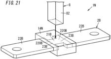
- the electrical conductor 2B has a different shape from the electrical conductor 2 according to the first embodiment.
- the dimension of the separable portion 21B is smaller than the dimension of the two terminal portions 22B.
- the direction in which the actuator pin 8 advances is aligned with the thickness of the separable portion 21B.
- the direction in which an electric current flows through the electrical conductor 2B is aligned with the longitudinal axis of the electrical conductor 2B.
- the dimension of the separable portion 21B when measured along the latitudinal axis of the electrical conductor 2B, the dimension of the separable portion 21B is smaller than the dimension of the two terminal portions 22B.
- the electrical conductor 2B is recessed from both sides along the latitudinal axis thereof. That is to say, the electrical conductor 2B has two recesses 230.
- the breaking strength of the boundary portion 23B between the separable portion 21B and each terminal portion 22B is smaller than the breaking strength of the rest of the terminal portion 22B other than the boundary portion 23B.
- the dimension of the boundary portion 23B is equal to the dimension of the separable portion 21B.
- each boundary portion 23B When measured in a direction perpendicular to the direction in which the actuator pin 8 advances and intersecting with the direction in which the electric current flows through each boundary portion 23B (i.e., when measured along the latitudinal axis of the electrical conductor 2B), the dimension of each adjacent portion 220B is larger than the dimension of the boundary portion 23B adjacent to the adjacent portion 220B. Specifically, the difference in dimension between the adjacent portion 220B and the boundary portion 23B is equal to the sum of the respective lengths of the two recesses 230 provided for the electrical conductor 2B.
- the electrical conductor 2B may be recessed at the separable portion 21B from either side along the latitudinal axis of the electrical conductor 2B.
- the groove 24 may also be provided in this embodiment in the boundary portion 23B between the separable portion 21B and each terminal portion 22B of the electrical conductor 2B.
- the dimension of the separable portion 21B when measured in the direction in which the actuator pin 8 advances, the dimension of the separable portion 21B may also be smaller in this embodiment than the dimension of the two terminal portions 22B.
- the third embodiment described above may be a specific implementation of the following aspect of the present disclosure.
- the dimension of the separable portion 21B when measured in the direction perpendicular to the direction in which the actuator pin 8 advances and the direction in which the electric current flows through the electrical conductor 2B, the dimension of the separable portion 21B is smaller than the dimension of each terminal portion 22B.
- This configuration facilitates cutting off the separable portion 21B from the terminal portions 22B.
- FIGS. 8 , 9A, and 9B An interrupter 1C according to a fourth embodiment will now be described with reference to FIGS. 8 , 9A, and 9B .
- any constituent element of this fourth embodiment, having the same function as a counterpart of the first embodiment described above, will be designated by the same reference numeral as that counterpart's, and description thereof will be omitted herein.
- the interrupter 1C further includes a plurality of (e.g., two in the example illustrated in FIG 8 ) permanent magnets 61.
- the separable portion 21C is also located between the actuator pin 8 and the housing space 98C in the direction in which the actuator pin 8 advances.
- the plurality of permanent magnets 61 are arranged to apply Lorentz force to an electric current flowing through the electrical conductor 2C such that the Lorentz force is directed from the electrical conductor 2C toward the housing space 98C.
- the interrupter 1C further includes a plurality of (e.g., two in the example illustrated in FIG 8 ) positioning members 62.
- Each of the two positioning members 62 may be made of a resin, for example.
- the two positioning members 62 are mounted onto a surface 951, facing the first body 91C, of the second body 95C of the housing portion 9C.
- Each positioning member 62 has two recesses 621.
- the two recesses 621 of one positioning member 62 correspond one to one to the two recesses 621 of the other positioning member 62.
- the two positioning members 62 are in contact with each other and each pair of recesses 621 facing each other are connected together.
- the two permanent magnets 61 are positioned between the two positioning members 62. More specifically, one permanent magnet 61 is arranged inside one pair of recesses 621, facing each other, of the two positioning members 62 and the other permanent magnet 61 is arranged inside the other pair of recesses 621, facing each other, of the two positioning members 62.
- One of the two positioning members 62 has a groove 622, to which one of the two terminal portions 22C of the electrical conductor 2C is fitted.
- the other of the two positioning members 62 has a groove 622, to which the other of the two terminal portions 22C of the electrical conductor 2C is fitted.
- Each positioning member 62 has a recess 623.
- the respective recesses 623 of the two positioning members 62 are connected together.
- the space 981 inside the respective recesses 623 of the two positioning members 62 forms part of the housing space 98C to house the separable portion 21C that has been cut off from the two terminal portions 22C.
- the second body 95 has a recess 952C connected to the space 981 which faces the separable portion 21C via the respective recesses 623 of the two positioning members 62.
- the space 982 inside the recess 952C forms part of the housing space 98C.
- An arc quenching member 13 is attached to the inner surface of the recess 623 of each positioning member 62.
- the arc quenching member 13 may be embedded in the inner surface of the recess 623.
- the electrical conductor 2C also has two grooves 24. Both latitudinal ends of the electrical conductor 2C are recessed at the separable portion 21C.
- an electric current flows, for example, to the right on the paper on which FIG 9A is drawn.
- the two permanent magnets 61 are arranged along a normal to the paper on which FIG 9A is drawn.
- the permanent magnet 61 located behind the paper on which FIG 9A is drawn i.e., located more distant from the viewer who is looking straight at FIG. 9A
- orients its N pole toward the permanent magnet 61 located in front of the paper on which FIG 9A is drawn i.e., located closer to the viewer who is looking straight at FIG. 9A
- the permanent magnet 61 located in front of the paper on which FIG 9A is drawn orients its S pole toward the permanent magnet 61 located behind the paper on which FIG 9A is drawn.
- the magnetic flux generated by the two permanent magnets 61 causes Lorentz force to be applied to an electric current flowing through the electrical conductor 2C such that the Lorentz force is directed toward the housing space 98C. That is to say, Lorentz force is applied downward (on the paper on which FIG 9A is drawn) to the electric current flowing through the electrical conductor 2C.
- Lorentz force is applied downward (on the paper on which FIG 9A is drawn) to the electric current flowing through the electrical conductor 2C.
- two permanent magnets 61 are provided.
- the number of the permanent magnet(s) 61 provided may also be one or three or more.
- the fourth embodiment described above may be a specific implementation of the following aspect of the present disclosure.
- An interrupter 1C according to the fourth embodiment further includes a permanent magnet 61.
- the separable portion 21C is located between the actuator pin 8 and the housing space 98C.
- the permanent magnet 61 is arranged to apply Lorentz force to an electric current flowing through the electrical conductor 2C. The Lorentz force is directed toward the housing space 98C.
- This configuration allows the arc generated when the separable portion 21C is cut off from the terminal portions 22C to be stretched toward the housing space 98C by the Lorentz force applied to the arc.
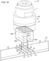
- the electrical conductor 2D includes a plurality of separable portions 21D. More specifically, the electrical conductor 2D includes two separable portions 21D. In the following description, when there is a need to distinguish them from each other, the two separable portions 21D will be hereinafter sometimes referred to as a "first separable portion 211" and a “second separable portion 212,” respectively.
- the electrical conductor 2D includes two terminal portions 22D, the first separable portion 211, and the second separable portion 212.
- Each of the two terminal portions 22D includes a terminal portion body 223, a first terminal part 221, and a second terminal part 222. That is to say, the electrical conductor 2D includes two first terminal parts 221 and two second terminal parts 222.
- the first separable portion 211 is connected to the two first terminal parts 221.
- the second separable portion 212 is connected to the two second terminal parts 222.
- the second separable portion 212 is electrically connected to the first separable portion 211 in parallel via the first terminal parts 221 and the second terminal parts 222.
- the first separable portion 211 and the second separable portion 212 are housed in the housing portion 9 (housing).
- One end of each of the two terminal portion bodies 223 protrudes out of the housing portion 9 and is electrically connected to the terminal 208 (see FIG 5 ).
- the first terminal part 221 and the second terminal part 222 protrude. That is to say, the second terminal part 222 is electrically connected to the first terminal part 221 via the terminal portion body 223.
- the first separable portion 211 is connected between the two first terminal parts 221 protruding from the respective terminal portion bodies 223.
- the second separable portion 212 is connected between the two second terminal parts 222 protruding from the respective terminal portion bodies 223.
- the actuator pin 8 cuts off the first separable portion 211 from the two first terminal parts 221 and also cuts off the second separable portion 212 from the two second terminal parts 222, the external electric circuit EC10 (see FIG 5 ) is interrupted.
- Each of the first separable portion 211 and the second separable portion 212 forms part of an electric circuit. More specifically, each of the first separable portion 211 and the second separable portion 212 is directly connected to the two terminal portions 22D.
- the first separable portion 211 is connected to the two terminal portion bodies 223 via the two first terminal parts 221.
- the second separable portion 212 is connected to the two terminal portion bodies 223 via the two second terminal parts 222.
- the first separable portion 211 and the second separable portion 212 are electrically connected in parallel. More specifically, a first series electric circuit (electrically conductive plate) including the two first terminal parts 221 and the first separable portion 211 provided between the two first terminal parts 221 and a second series electric circuit (electrically conductive plate) including the two second terminal parts 222 and the second separable portion 212 provided between the two second terminal parts 222 are electrically connected in parallel between the two terminal portion bodies 223.
- an insert hole 213 is provided between the first series electric circuit and the second series electric circuit (i.e., between the first separable portion 211 and the second separable portion 212).
- a protruding member 82D of the actuator pin 8 includes an insert portion 87 and two pressing portions 88.
- the insert portion 87 protrudes from the base 81 of the actuator pin 8.
- the insert portion 87 has a rectangular parallelepiped shape.
- the insert portion 87 is inserted into the insert hole 213 of the electrical conductor 2D. This allows the actuator pin 8 to be positioned in a direction perpendicular to the direction in which the insert portion 87 protrudes from the base 81.
- the two pressing portions 88 protrude from the insert portion 87.
- the direction in which the two pressing portions 88 protrude intersects with the direction in which the insert portion 87 protrudes from the base 81.
- the two pressing portions 88 protrude in mutually opposite directions.
- the two pressing portions 88 are provided one to one for their associated two separable portions 21D.
- the distance between the first separable portion 211 and the actuator pin 8D facing the first separable portion 211 and the distance between the second separable portion 212 and the actuator pin 8D facing the second separable portion 212 are both equal to zero.
- the actuator pin 8D is illustrated as being separate from the first separable portion 211 and the second separable portion 212 for the sake of convenience.
- One of the two pressing portions 88 of the actuator pin 8D presses the first separable portion 211, thus cutting off the first separable portion 211 from the two first terminal parts 221 (terminal portions 22D).
- the other of the two pressing portions 88 presses the second separable portion 212, thus cutting off the second separable portion 212 from the two second terminal parts 222 (terminal portions 22D).
- each pressing portion 88 presses its associated separable portion 21D. More specifically, the respective pressing portions 88 press their associated separable portions 21D simultaneously.
- the timing when one of the two pressing portions 88 of the actuator pin 8D presses the first separable portion 211 is the same as the timing when the other of the two pressing portions 88 presses the second separable portion 212.
- the respective pressing portions 88 press their associated separable portions 21D, the respective separable portions 21D start to be cut off from the two terminal portions 22D simultaneously. Then, the respective separable portions 21D will be completely cut off from the two terminal portions 22D. The respective separable portions 21D will be cut off from the terminal portions 22D at the same timing.
- the electrical conductor 2D may include three or more separable portions 21D.
- the interrupter 1D may include, instead of the actuator pin 8D, the same number of actuator pins 8, each having the same configuration as its counterpart of the first embodiment (see FIG 3 ), as the separable portions 21D provided.
- the interrupter 1D may include the same number of gas producers 7 (see FIG 3 ) as the separable portions 21D provided.
- the plurality of separable portions 21D are associated one to one with the plurality of actuator pins 8.
- the plurality of actuator pins 8 are associated one to one with the plurality of gas producers 7.
- Each gas producer 7 may be configured to drive an associated one of the actuator pins 8 and each actuator pin 8 may be configured to press an associated one of the separable portions 21D. This allows, even when the electrical conductor 2D has a greater thickness and a greater width, the respective separable portions 21D to be cut off from the two terminal portions 22D.
- first separable portion 211 and the second separable portion 212 may be electrically connected in series (see the seventh embodiment and FIG. 18 ).
- a single part may be used as both the first terminal part 221 and the second terminal part 222.
- the housing space 98 (see FIG 2 ) of the housing portion 9 (see FIG 2 ) may house at least one of the first and second separable portions 211, 212 cut off from the two terminal portions 22D.
- the fifth embodiment described above may be a specific implementation of the following aspects of the present disclosure.
- the electrical conductor 2D includes a plurality of separable portions 21D. Two out of the plurality of separable portions 21D serve as a first separable portion 211 and a second separable portion 212, respectively.
- the first separable portion 211 and the second separable portion 212 are electrically connected in either series or parallel.
- the actuator pin 8D cuts off the first separable portion 211 from the terminal portion 22D by pressing the first separable portion 211 and also cuts off the second separable portion 212 from the terminal portion 22D by pressing the second separable portion 212.
- a distance between the first separable portion 211 and the actuator pin 8D facing the first separable portion 211 is equal to a distance between the second separable portion 212 and the actuator pin 8D facing the second separable portion 212 when measured in a direction in which the actuator pin 8D advances.
- the first separable portion 211 and the second separable portion 212 are electrically connected in parallel, then an electric current on the electric circuit EC1 will flow separately through the plurality of separable portions 21D. This reduces the amount of electric current flowing through each separable portion 21D, thus facilitating cutting off the arc.
- the first separable portion 211 and the second separable portion 212 are electrically connected in series, then the arc voltage generated between the first separable portion 211 and the second separable portion 212 will be divided and distributed in the first separable portion 211 and the second separable portion 212. This causes an increase in arc voltage, thus allowing the interrupter 1D to have improved arc quenching capability.
- the electrical conductor 2D includes a plurality of separable portions 21D. Two out of the plurality of separable portions 21D serve as a first separable portion 211 and a second separable portion 212, respectively.
- the first separable portion 211 and the second separable portion 212 are electrically connected in either series or parallel.
- the actuator pin 8D cuts off the first separable portion 211 from each terminal portion 22D by pressing the first separable portion 211 and also cuts off the second separable portion 212 from the terminal portion 22D by pressing the second separable portion 212.
- a timing when the actuator pin 8D presses the first separable portion 211 is the same as a timing when the actuator pin 8D presses the second separable portion 212.
- the first separable portion 211 and the second separable portion 212 are electrically connected in parallel, then an electric current on the electric circuit EC1 will flow separately through the plurality of separable portions 21D. This reduces the amount of electric current flowing through each separable portion 21D, thus facilitating cutting off the arc.
- the first separable portion 211 and the second separable portion 212 are electrically connected in series, then the arc voltage generated between the first separable portion 211 and the second separable portion 212 will be divided and distributed in the first separable portion 211 and the second separable portion 212. This causes an increase in arc voltage, thus allowing the interrupter 1D to have improved arc quenching capability.
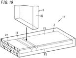
- the electrical conductor 2E includes a first member 3 and a second member 4.
- the first member 3 includes a first separable portion 31 and two first terminal portions 32.
- the second member 4 includes a second separable portion 41 and two second terminal portions 42. That is to say, the electrical conductor 2E includes a plurality of (e.g., two in the example illustrated in FIG 11 ) separable portions.
- the electrical conductor 2E includes a plurality of (e.g., four in the example illustrated in FIG. 11 ) terminal portions.
- the interrupter 1E is electrically connected to the two terminals 208 (see FIG 5 ) of the external electric circuit EC10 (see FIG 5 ). That is to say, the two first terminal portions 32 are associated one to one with the two terminals 208 and electrically connected to their associated terminals 208, respectively. Likewise, the two second terminal portions 42 are associated one to one with the two terminals 208 and electrically connected to their associated terminals 208, respectively. The second member 4 is electrically connected to the first member 3 in parallel between the two terminals 208.
- the first separable portion 31 is connected to the two first terminal portions 32.
- the second separable portion 41 is connected to the two second terminal portions 42.
- the second separable portion 41 is electrically connected to the first separable portion 31 in parallel. More specifically, each pair of first and second terminal portions 32, 42 adjacent to each other are electrically connected to each other by coming into contact with each other. Furthermore, in this embodiment, the first separable portion 31 and second separable portion 41 adjacent to each other are electrically connected to each other by coming into contact with each other.
- a state where the first separable portion 31 and the second separable portion 41 are electrically connected in parallel may refer to such an arrangement in which the first separable portion 31 and the second separable portion 41 are arranged side by side and in contact with each other.
- the two first terminal portions 32 are formed integrally with the first separable portion 31.
- the two second terminal portions 42 are formed integrally with the second separable portion 41.
- Each of the first member 3 and the second member 4 has the same shape as the electrical conductor 2 (see FIG 2 ) according to the first embodiment. Specifically, in the first member 3, grooves 34 are provided on the two boundary portions 33 between the first separable portion 31 and the two first terminal portions 32. In the second member 4, grooves 44 are provided on the two boundary portions 43 between the second separable portion 41 and the two second terminal portions 42.
- the first separable portion 31 is cut off from the two first terminal portions 32 by the actuator pin 8 that has been driven under the pressure of the gas produced by the gas producer 7 (see FIG 3 ).
- the second separable portion 41 is cut off from the two second terminal portions 42 by the actuator pin 8 that has been driven under the pressure of the gas produced by the gas producer 7.
- first timing the timing when the first separable portion 31 starts to be cut off from the two first terminal portions 32
- second timing the timing when the second separable portion 41 starts to be cut off from the two second terminal portions 42
- the first separable portion 31 and the second separable portion 41 are arranged side by side in the direction in which the actuator pin 8 advances.
- the first separable portion 31 and the second separable portion 41 are arranged side by side in a first direction.
- the first direction is the direction in which the actuator pin 8 advances (i.e., downward direction on the paper on which FIG 11 is drawn).
- the first member 3 and the second member 4 are connected together on their respective surfaces opposite from the surfaces with the grooves 34, 44. More specifically, the first member 3 and the second member 4 are connected together by brazing, for example. That is to say, at a point in time prior to the first timing, the first separable portion 31 is bonded by brazing to the second separable portion 41.
- Each of the first separable portion 31 and second separable portion 41 forms part of an electric circuit. More specifically, the first separable portion 31 is directly connected to the two first terminal portions 32. The second separable portion 41 is directly connected to the two second terminal portions 42.
- the first separable portion 31 and the two first terminal portions 32 may be made of copper, for example.
- the second separable portion 41 and the two second terminal portions 42 may be made of tungsten, for example.
- the electrical conductivity of the first separable portion 31 is higher than the electrical conductivity of the second separable portion 41.
- the electrical resistance of the first separable portion 31 as measured in a direction in which an electric current flows through the first separable portion 31 is smaller than the electrical resistance of the second separable portion 41 as measured in a direction in which an electric current flows through the second separable portion 41.
- the electrical resistance of the first separable portion 31 is smaller than the electrical resistance of the second separable portion 41.
- the second direction is a direction perpendicular to the first direction and aligned with the direction in which the first separable portion 31 and the second separable portion 41 are extended (i.e., rightward/leftward direction on the paper on which FIG 11 is drawn).
- the direction in which an electric current (i.e., an electric current flowing between the two first terminal portions 32) flows through the first separable portion 31 and the direction in which an electric current (i.e., an electric current flowing between the two second terminal portions 42) flows through the second separable portion 41 are both aligned with the rightward/leftward direction on the paper on which FIG 11 is drawn.
- the melting point of the second separable portion 41 is higher than the melting point of the first separable portion 31.
- a point in time when no gas is produced yet by the gas producer 7 is a point in time before the first separable portion 31 is cut off from the two first terminal portions 32 and before the second separable portion 41 is cut off from the two second terminal portions 42.
- the distance between the first separable portion 31 and the actuator pin 8 is shorter than the distance between the second separable portion 41 and the actuator pin 8. More specifically, the tip 86 of the protruding member 82 of the actuator pin 8 is in contact with the first separable portion 31. That is to say, when measured in the direction in which the actuator pin 8 advances, the distance between the first separable portion 31 and the actuator pin 8 is zero.
- the first separable portion 31 is located between the second separable portion 41 and the protruding member 82.
- the actuator pin 8 is movable in the first direction (i.e., downward direction on the paper on which FIG 11 is drawn).
- the first separable portion 31 and the second separable portion 41 are extended in the second direction (i.e., rightward/leftward direction on the paper on which FIG 11 is drawn) perpendicular to the first direction.
- An electric current flows in the second direction through the first separable portion 31 and the second separable portion 41.
- a direction perpendicular to both the first direction and the second direction will be hereinafter referred to as a "third direction" (a direction aligned with a normal to the paper on which FIG 11 is drawn).
- the distance L1 as measured in the first direction between the actuator pin 8 and the second separable portion 41 is longer, when viewed in the third direction, than the distance (of zero) as measured in the first direction between the actuator pin 8 and the first separable portion 31.
- the timing when the actuator pin 8 presses the first separable portion 31 is earlier than the timing when the actuator pin 8 presses the second separable portion 41.
- a first timing when the first separable portion 31 starts to be cut off from the two first terminal portions 32 by the actuator pin 8 is earlier than a second timing when the second separable portion 41 starts to be cut off from the two second terminal portions 42 by the actuator pin 8.
- the second separable portion 41 is pressed by the actuator pin 8 and thereby cut off from the two second terminal portions 42.
- an arc may be generated between the second separable portion 41 and the two second terminal portions 42.
- the melting point of the second separable portion 41 is higher than the melting point of the first separable portion 31.
- a metallic vapor is produced less easily from the second separable portion 41 than from the first separable portion 31. That is why the arc generated between the second separable portion 41 and the two second terminal portions 42 may be cut off more easily than the arc generated between the first separable portion 31 and the two first terminal portions 32.
- the electrical conductivity of the first separable portion 31 is higher than the electrical conductivity of the second separable portion 41.
- the electrical conductor 2E may be electrified more smoothly compared to a situation where the electrical conductor 2E includes the second separable portion 41 but does not include the first separable portion 31.
- the electrical resistance of the first separable portion 31 is smaller than the electrical resistance of the second separable portion 41. This may reduce generation of an arc from the electrical conductor 2E before the actuator pin 8 is driven, compared to a situation where the electrical conductor 2E does not include the second separable portion 41.
- interrupter 1E This allows the interrupter 1E according to this embodiment to have improved arc quenching capability while maintaining electrification capability, compared to the interrupter 1 according to the first embodiment.
- first member 3 and the second member 4 do not have to be bonded together by brazing but may also be bonded together by welding, screwing, snap-fitting, or any other suitable means.
- first member 3 and the second member 4 do not have to be connected (bonded) together by brazing or any other suitable means but the second member 4 may be just put on the first member 3.
- first member 3 may be just put on the second member 4. That is to say, at a point in time prior to the first timing, the first separable portion 31 may be connected to, or in contact with, the second separable portion 41.
- first separable portion 31 does not have to be cut off from both of the two first terminal portions 32 but may be cut off from at least one of the two first terminal portions 32.
- the first timing may be a timing when the first separable portion 31 starts to be cut off from at least one of the two first terminal portions 32.
- second separable portion 41 does not have to be cut off from both of the two second terminal portions 42 but may be cut off from at least one of the two second terminal portions 42.
- the second timing may be a timing when the second separable portion 41 starts to be cut off from at least one of the two second terminal portions 42.
- the first separable portion 31 and the second separable portion 41 at least the first separable portion 31 needs to be cut off from at least one of the two first terminal portions 32.
- the second separable portion 41 does not have to be cut off from at least one of the two second terminal portions 42. That is to say, the actuator pin 8 driven under the pressure of the gas produced by the gas producer 7 needs to cut off at least the first separable portion 31 from the terminal portions, out of the first separable portion 31 and the second separable portion 41.
- At least one of the first member 3 or the second member 4 may be provided with a single or a plurality of holes instead of the grooves 34 (or 44).
- at least one of the first separable portion 31 or the second separable portion 41 may include a portion, of which the thickness and/or width is/are smaller than that of a surrounding member thereof, instead of the grooves 34 (or 44).
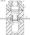
- FIGS. 12-16 An interrupter 1F according to a first variation of the sixth embodiment will now be described with reference to FIGS. 12-16 .
- any constituent element of this first variation having the same function as a counterpart of the sixth embodiment described above, will be designated by the same reference numeral as that counterpart's, and description thereof will be omitted herein.
- the first separable portion 31 and second separable portion 41 of the electrical conductor 2F are out of contact with each other in the direction in which the actuator pin 8 advances. That is to say, at a point in time prior to the first timing when the first separable portion 31 starts to be cut off from the two first terminal portions 32, the first separable portion 31 and the second separable portion 41 are arranged side by side and spaced apart from each other in the direction in which the actuator pin 8 advances. In addition, before the actuator pin 8 is driven, the first separable portion 31 and the second separable portion 41 are arranged side by side and spaced apart from each other in a first direction. As used herein, the first direction refers to the direction in which the actuator pin 8 advances (i.e., the downward direction on the paper on which FIG 12 is drawn).
- the first separable portion 31 is connected to the two first terminal portions 32.
- the second separable portion 41 is connected to the two second terminal portions 42.
- the second separable portion 41 is electrically connected to the first separable portion 31 in parallel via two second terminal portions 42F.
- the second member 4 includes the two second terminal portions 42F instead of the two second terminal portions 42 (see FIG 11 ). Each of the two second terminal portions 42 is bent. Each of the two second terminal portions 42F is connected to the second separable portion 41 and forms part of an electric circuit.
- FIG 12 illustrate an exemplary configuration for the second member 4F.
- FIGS. 13-16 illustrate another exemplary configuration for the second member 4F.
- the second member 4F is less than the first member 3.
- the second member 4F has two grooves 44 provided between the second separable portion 41 and two second terminal portions 42F of the second member 4F. The two grooves 44 are formed to be recessed in the direction in which the actuator pin 8 advances.
- the second member 4F has four grooves 44, which make the second member 4F recessed from both ends of the width (i.e., along a normal to the paper on which FIG 14 is drawn) of the first member 3.
- FIGS. 13-16 illustrate another exemplary configuration for the second member 4F.
- the second member 4F is less than the first member 3.
- the second member 4F has two grooves 44 provided between the second separable portion 41 and two second terminal portions 42F of the second member 4F. The two grooves 44 are formed to be recessed in the direction in which the actuator pin 8 advances.
- the second member 4F
- an arc-shaped groove 34 is provided between the first separable portion 31 and each first terminal portion 32 of the first member 3.
- the interrupter 1F shown in FIG 12 has the same configuration as the interrupter 1F shown in FIGS. 13-16 .
- both the first separable portion 31 and second separable portion 41 are cut off from the two first terminal portions 32 and the two second terminal portions 42, respectively (see FIGS. 12 and 14 ), when measured in the direction in which the actuator pin 8 advances, the distance between the first separable portion 31 and the actuator pin 8 is shorter than the distance between the second separable portion 41 and the actuator pin 8. When measured in the direction in which the actuator pin 8 advances, the distance between the first separable portion 31 and the actuator pin 8 is zero.
- One of the two second terminal portions 42F of the second member 4F is connected to one of the two first terminal portions 32 of the first member 3.
- the other of the two second terminal portions 42F is connected to the other of the two first terminal portions 32 of the first member 3.
- the interrupter 1F further includes two rivets 25.
- Each of the two second terminal portions 42F is connected to an associated first terminal portion 32 via an associated one of the rivets 25.
- the second terminal portions 42F are fixed to the first terminal portions 32 at one and the other ends of the second member 4F.
- one of the two second terminal portions 42F is fixed to one of the two first terminal portions 32.
- the other of the two second terminal portions 42F is fixed to the other of the two first terminal portions 32.
- Each of the two second terminal portions 42F is bent in a crank shape between the rivet 25 and the second separable portion 41.
- the second separable portion 41 is out of contact with the first separable portion 31 in the direction in which the actuator pin 8 advances.
- the timing when the actuator pin 8 presses the first separable portion 31 is earlier than the timing when the actuator pin 8 presses the second separable portion 41.
- the first separable portion 31 is cut off from the two first terminal portions 32 by the actuator pin 8 (see FIG 15 )
- the second separable portion 41 is still not cut off yet from the two second terminal portions 42.
- the second separable portion 41 will be cut off from the two second terminal portions 42 by the actuator pin 8 (see FIG 16 ).
- the timing when the first separable portion 31 starts to be cut off by the actuator pin 8 is earlier than the timing when the second separable portion 41 starts to be cut off by the actuator pin 8.
- a gap may be left as shown in FIG 16 in the housing space 98 in the direction in which the actuator pin 8 advances.
- the second separable portion 41 is out of contact with the first separable portion 31 in the direction in which the actuator pin 8 advances. This reduces the chances of the arc generated between the second separable portion 41 and the two second terminal portions 42F moving to between the first separable portion 31 and the two first terminal portions 32. This further reduces the generation of the arc from the first separable portion 31 after the first separable portion 31 has been cut off from the two first terminal portions 32.
- the electrical resistance of the electrical conductor 2F increases from its value before the first separable portion 31 is broken. This reduces the amount of electric current flowing through the electrical conductor 2f, thus reducing the generation of the arc.
- the electrical resistance of the first separable portion 31 as measured in the direction in which an electric current flows through the first separable portion 31 is suitably smaller than the electrical resistance of the second separable portion 41 as measured in the direction in which an electric current flows through the second separable portion 41. This further reduces the generation of the arc from the electrical conductor 2F.
- interrupter 1M according to a second variation of the sixth embodiment will now be described with reference to FIG 17 .
- the interrupter 1M according to this second variation is implemented to have, in combination, the features of the interrupter 1D according to the fifth embodiment and the features of the interrupter 1F according to the first variation of the sixth embodiment.
- any constituent element of this second variation having the same function as a counterpart of the fifth embodiment described above, will be designated by the same reference numeral as that counterpart's, and description thereof will be omitted herein.
- FIG 17 illustrates a state before the actuator pin 8 is driven.
- the first separable portion 211 and the second separable portion 212 are located at mutually different positions not only in the direction in which the actuator pin 8D advances but also in a direction intersecting with the in the direction in which the actuator pin 8D advances and the longitudinal axis of the electrical conductor 2M.
- the two second terminal parts 222 according to this second variation are bent unlike the two second terminal parts 222 according to the fifth embodiment, thus making the second separable portion 212 located deeper in the direction in which the actuator pin 8D advances than the first separable portion 211 is.
- the distance as measured in the first direction between the actuator pin 8D and the second separable portion 212 is longer when viewed in the third direction than the distance as measured in the first direction between the actuator pin 8D and the first separable portion 211.
- the first direction is a direction in which the actuator pin 8D moves.
- the third direction is perpendicular to both the first direction and the second direction (i.e., a direction perpendicular to the first direction and aligned with a direction in which the first separable portion 211 and the second separable portion 212 are extended).
- the actuator pin 8D When the actuator pin 8D is driven under the pressure of the gas produced by the gas producer 7, one of the two pressing portions 88 of the actuator pin 8D presses the first separable portion 211, thus cutting off the first separable portion 211 from the two first terminal parts 221. As the actuator pin 8D further advances, the other of the two pressing portions 88 presses the second separable portion 212, thus cutting off the second separable portion 212 from the two second terminal parts 222. That is to say, according to this second variation, the first timing when the first separable portion 211 starts to be cut off from the two first terminal parts 221 is earlier than the second timing when the second separable portion 212 starts to be cut off from the two second terminal parts 222.
- This second variation allows the thickness of the electrical conductor 2M to be reduced compared to the first variation of the sixth embodiment.
- the electrical conductor 2M may be manufactured by subjecting a single plate member with electrical conductivity to pressing. Specifically, the insert hole 213 is opened by subjecting a single plate member to press punching and then two second terminal parts 222 are bent by press bending, thereby manufacturing the electrical conductor 2M. This reduces, compared to the electrical conductor 2E according to the sixth embodiment, the number of members as materials for the electrical conductor 2M.
- the second separable portion 212 may be less thick than the first separable portion 211.
- the thickness of the first separable portion 211 may be larger than the thickness of the second separable portion 212.
- the first direction is a direction in which the actuator pin 8D moves.
- the electrical resistance of the first separable portion 211 as measured in a direction in which an electric current flows through the first separable portion 211 may be set at a value smaller than the electrical resistance of the second separable portion 212 as measured in a direction in which an electric current flows through the second separable portion 212.
- At least one of the two second terminal parts 222 may be less thick than the first separable portion 211.
- the second separable portion 212 and the two second terminal parts 222 may be compressed along their thickness by press compression to have a smaller thickness than the first separable portion 211.
- the thickness of the first separable portion 31 when measured in the first direction, may be larger than the thickness of the second separable portion 41.
- the first timing when the first separable portion 31 (or 211) starts to be cut off from the first terminal portion 32 (or first terminal part 221) is earlier than the second timing when the second separable portion 41 (or 212) starts to be cut off from the second terminal portion 42 (42F, or second terminal part 222).
- This configuration may reduce generation of an arc from the first separable portion 31 (or 211) compared to a situation where the electrical conductor 2E (or 2F, 2M) has only one separable portion.
- the electrical conductor 2E includes a plurality of separable portions. Two out of the plurality of separable portions serve as a first separable portion 31 (or 211) and a second separable portion 41 (or 212), respectively.
- the actuator pin 8 cuts off the first separable portion 31 (or 211) from the terminal portion (first terminal portion 32 or first terminal part 221) by pressing the first separable portion 31 (or 211) and also cuts off the second separable portion 41 (or 212) from the terminal portion (second terminal portion 42, 42F, or second terminal part 222) by pressing the second separable portion 41 (or 212).
- a distance between the first separable portion 31 (or 211) and the actuator pin 8 (or 8D) is shorter than a distance L1 (or L2) between the second separable portion 41 (or 212) and the actuator pin 8 (or 8D) when measured in the direction in which the actuator pin 8 (or 8D) advances.
- This configuration may reduce generation of an arc from the first separable portion 31 (or 211).
- the electrical conductor 2E (or 2F, 2M) includes a plurality of separable portions. Two out of the plurality of separable portions serve as a first separable portion 31 (or 211) and a second separable portion 41 (or 212), respectively.
- the actuator pin 8 (or 8D) cuts off the first separable portion 31 (or 211) from the terminal portion (first terminal portion 32 or first terminal part 221) by pressing the first separable portion 31 (or 211) and also cuts off the second separable portion 41 (or 212) from the terminal portion (second terminal portion 42, 42F, or second terminal part 222) by pressing the second separable portion 41 (or 212).
- the timing when the actuator pin 8 (or 8D) presses the first separable portion 31 (or 211) is earlier than the timing when the actuator pin 8 (or 8D) presses the second separable portion 41 (or 212).
- This configuration may reduce generation of an arc from the first separable portion 31 (or 211).
- the interrupter 1E (or 1F) according to the sixth embodiment and the first variation thereof at a point in time prior to the first timing, the first separable portion 31 and the second separable portion 41 are arranged side by side in the direction in which the actuator pin 8 advances.
- This configuration allows the first separable portion 31 and the second separable portion 41 to be easily cut off from the terminal portions (first terminal portion 32 and the second terminal portion 42) by the actuator pin 8.
- the first separable portion 31 (or 211) and the second separable portion 41 (or 212) are arranged side by side and spaced apart from each other in the direction in which the actuator pin 8 (or 8D) advances.
- This configuration facilitates causing a time lag between the first timing and the second timing, thus reducing generation of an arc from the first separable portion 31 (or 211) more easily.
- the first separable portion 31 is either in contact with, or joined to, the second separable portion 41.
- This configuration makes the installation space of the electrical conductor 2D reducible, compared to a situation where the first separable portion 31 and the second separable portion 41 are provided out of contact with each other.
- the electrical resistance of the first separable portion 31 (or 211) as measured in a direction in which an electric current flows through the first separable portion 31 (or 211) is smaller than the electrical resistance of the second separable portion 41 (or 212) as measured in a direction in which an electric current flows through the second separable portion 41 (or 212).
- This configuration may reduce generation of an arc compared to a situation where the electrical conductor 2E (or 2F, 2M) has only one separable portion.
- the electrical conductivity of the first separable portion 31 is higher than the electrical conductivity of the second separable portion 41.
- This configuration allows a larger amount of current to flow through the first separable portion 31.
- the melting point of the second separable portion 41 is higher than the melting point of the first separable portion 31.
- the second separable portion 41 may still be not cut off yet from the terminal portion (second terminal portion 42 or second terminal portion 42F) and a state where the electric circuit EC1 (see FIG 5 ) is electrically conductive may be maintained. In that case, an arc may be generated more easily when the second separable portion 41 is cut off from the terminal portion than when the first separable portion 31 is cut off from the terminal portion.
- the melting point of the second separable portion 41 is higher than the melting point of the first separable portion 31, thus making the arc quenchable more easily in the second separable portion 41 than in the first separable portion 31.
- the actuator pin 8 (or 8D) is movable in a first direction.
- the first separable portion 31 (or 211) and the second separable portion 41 (or 212) are extended in a second direction.
- the second direction is perpendicular to the first direction.
- a distance L1 (or L2) measured in the first direction between the actuator pin 8 (or 8D) and the second separable portion 41 (or 212) is longer, when viewed in a third direction, than a distance measured in the first direction between the actuator pin 8 (or 8D) and the first separable portion 31 (or 211).
- the third direction is perpendicular to both the first direction and the second direction.
- This configuration may reduce generation of an arc from the first separable portion 31 (or 211).
- the first separable portion 31 and the second separable portion 41 are arranged side by side in the first direction.
- This configuration allows the first separable portion 31 and the second separable portion 41 to be easily cut off from the terminal portions (first terminal portion 32 and second terminal portion 42, 42F) by the actuator pin 8.
- the first separable portion 31 and the second separable portion 41 are arranged side by side and spaced apart from each other in the first direction.
- This configuration facilitates causing a time lag between the first timing when the first separable portion 31 starts to be cut off from the first terminal portions 32 and the second timing when the second separable portion 41 starts to be cut off from the second terminal portions 42F, thus reducing generation of an arc from the first separable portion 31 more easily.
- the electrical resistance of the first separable portion 31 (or 211) as measured in the second direction is smaller than the electrical resistance of the second separable portion 41 (or 212) as measured in the second direction.
- This configuration may further reduce generation of an arc from the first separable portion 31 (or 211).
- the melting point of the second separable portion 41 is higher than the melting point of the first separable portion 31.
- This configuration allows the interrupter 1E (or 1F) to have improved arc quenching capability.
- the thickness of the first separable portion 31 (or 211) when measured in the first direction, is greater than the thickness of the second separable portion 41 (or 212).
- This configuration may further reduce generation of an arc from the first separable portion 31.
- the electrical conductor 2G has a plurality of (e.g., two in the example illustrated in FIG. 18 ) separable portions 21.
- the two separable portions 21 are electrically connected in series.
- the electrical conductor 2G includes the two separable portions 21, two terminal portions 22, and a coupling portion 26.
- One of the two terminal portions 22, one of the two separable portions 21, the coupling portion 26, the other of the two separable portions 21, and the other of the two terminal portions 22 are connected in this order in series.
- the second body 95 has two housing spaces 98 (see FIG 2 ).
- the two housing spaces 98 are associated one to one with the two separable portions 21.
- the respective separable portions 21 and their associated housing spaces 98 are arranged side by side in the direction in which the actuator pin 8G advances.
- the coupling portion 26 and the two terminal portions 22 are in contact with the second body 95 (see FIG 2 ).
- the boundary portion 23 between each terminal portion 22 and an associated one of the separable portions 21 has a groove 24.
- the boundary portion 27 between each separable portion 21 and the coupling portion 26 has a groove 28.
- the protruding member 82G of the actuator pin 8G includes a coupling piece 891 and two pressing pieces 892.
- the coupling piece 891 is connected to the base 81 of the actuator pin 8G
- the coupling piece 891 has a plate shape.
- the thickness of the coupling piece 891 is aligned with the direction in which the actuator pin 8G advances.
- the two pressing pieces 892 protrude from the coupling piece 891 in the direction in which the actuator pin 8G advances.
- the protrusion lengths of the two pressing pieces 892 are equal to each other.
- the two pressing pieces 892 are associated one to one with the two separable portions 21.
- the distance between one of the two separable portions 21 and the actuator pin 8G is equal to the distance between the other of the two separable portions 21 and the actuator pin 8G More specifically, when measured in the direction in which the actuator pin 8 advances, the distance between one of the two separable portions 21 and an associated one of the pressing pieces 892 is equal to the distance between the other of the two separable portions 21 and an associated one of the pressing pieces 892. Even more specifically, each of the two pressing pieces 892 is in contact with its associated separable portion 21.
- the distance between the first separable portion and the actuator pin 8G facing the first separable portion is equal to the distance between the second separable portion and the actuator pin 8G facing the second separable portion.
- the distance between each of the two separable portions 21 and the actuator pin 8G is zero.
- the actuator pin 8G is illustrated as being out of contact with the two separable portions 21 for the sake of convenience.
- One of the two pressing pieces 892 of the actuator pin 8G cuts off one of the two separable portions 21 (first separable portion) from the two terminal portions 22 by pressing the first separable portion.
- the other of the two pressing pieces 892 cuts off the other of the two separable portions 21 (second separable portion) from the two terminal portions 22 by pressing the second separable portion.
- the timing when one of the two pressing pieces 892 of the actuator pin 8G presses the first separable portion is the same as the timing when the other of the two pressing pieces 892 presses the second separable portion. That is to say, the two pressing pieces 892 are in contact with the two separable portions 21, respectively.
- the two pressing pieces 892 press the two separable portions 21 simultaneously. This causes the two separable portions 21 of the electrical conductor 2G to start to be cut off simultaneously from the two terminal portions 22 and the coupling portion 26. Then, the two separable portions 21 will be completely cut off from the two terminal portions 22 and the coupling portion 26.
- the timing when one of the two separable portions 21 starts to be completely cut off by the actuator pin 8G is the same as the timing when the other separable portion starts to be completely cut off by the actuator pin 8G
- the number of the separable portions 21 provided does not have to be two but may also be three or more. That is to say, three or more separable portions 21 may be electrically connected in series.
- At least one set selected from the group consisting of the set of the two separable portions 21D and two terminal portions 22D according to the fifth embodiment (see FIG 10 ), the set of the first member 3 and second member 4 according to the sixth embodiment (see FIG 11 ), and the set of the first member 3 and second member 4F according to the first variation of the sixth embodiment (see FIG 12 ) may be electrically connected to the two terminal portions 22 according to this embodiment in series or parallel. That is to say, according to this embodiment, out of the plurality of separable portions 21, at least two separable portions 21 need to be electrically connected in series.
- the two separable portions 21 are electrically connected in series, and therefore, an arc voltage generated between the two separable portions 21 is divided and distributed in the two separable portions 21. This causes an increase in the arc voltage, thus allowing the interrupter 1G to have improved arc quenching capability.
- FIGS. 19 , 20A, and 20B An interrupter 1H according to an eighth embodiment will now be described with reference to FIGS. 19 , 20A, and 20B .
- any constituent element of this eighth embodiment, having the same function as a counterpart of the first embodiment described above, will be designated by the same reference numeral as that counterpart's, and description thereof will be omitted herein.
- the interrupter 1H further includes an electrically insulating mask 14.
- the mask 14 may be made of a resin, for example.
- the mask 14 covers both ends, facing the respective terminal portions 22, of the separable portion 21 and at least one of the respective ends, facing the separable portion 21, of the two terminal portions 22 (i.e., at least one of the two adjacent portions 220).
- the mask 14 covers the entire separable portion 21 and both ends, facing the separable portion 21, of the two terminal portions 22 of the electrical conductor 2. That is to say, the mask 14 according to this embodiment covers the adjacent portions 220.
- the mask 14 covers the electrical conductor 2 from both sides of its thickness and from both sides of its width. That is to say, the mask 14 covers the first surface F1 of the electrical conductor 2. The first surface F1 faces the actuator pin 8 in the direction in which the actuator pin 8 advances. In addition, the mask 14 also covers the second surface F2 of the electrical conductor 2. The second surface F2 is opposite from the first surface F1 in the direction in which the actuator pin 8 advances. Besides, the mask 14 further covers two third surfaces F3 of the electrical conductor 2. A normal to each of the two third surfaces F3 is aligned with a direction perpendicular to the direction in which the actuator pin 8 advances and a direction in which an electric current flows through the electrical conductor 2.
- the electrical conductor 2 also includes two boundary portions 23 between the separable portion 21 and the two terminal portions 22.
- the dimension of each adjacent portion 220 is larger than the dimension of the boundary portion 23 adjacent to the adjacent portion 220.
- the direction in which the electric current flows through the boundary portions 23 is aligned with the longitudinal axis of the electrical conductor 2 (i.e., rightward/leftward direction on the paper on which FIG 20A is drawn).
- the predetermined direction intersecting with the direction in which the electric current flows through the boundary portions 23 is aligned with the direction in which the actuator pin 8 advances (i.e., the upward/downward direction on the paper on which FIG 20A is drawn).
- the protruding member 82 of the actuator pin 8 that has been driven under the pressure of the gas produced by the gas producer 7 (see FIG 3 ) breaks the electrical conductor 2 at the boundary portions 23 between the separable portion 21 and the respective terminal portions 22 to come into contact with cross sections of the respective terminal portions 22.
- the protruding member 82 also breaks the mask 14 along with the electrical conductor 2. The protruding member 82 comes into contact with cross sections of the mask 14 as well.
- the mask 14 regulates the emission of constituent particles of the arc from the respective terminal portions 22.
- the constituent particles of the arc include electrons, a metallic vapor, and plasma particles.
- the protruding member 82 of the actuator pin 8 further regulates the emission of the constituent particles of the arc from each terminal portion 22. More specifically, an end portion, facing the separable portion 21, of each terminal portion 22 (i.e., the adjacent portion 220) is covered with the protruding member 82 along the longitudinal axis of the electrical conductor 2 and is also covered with the mask 14 along the thickness and width of the electrical conductor 2.
- the mask 14 covers the adjacent portions 220, parts, covering the adjacent portions 220, of the mask 14 reduce the emission of the constituent particles of the arc when the boundary portions 23 adjacent to the adjacent portions 220 are broken.
- covering the separable portion 21 with the mask 14 along the thickness and width of the electrical conductor 2 regulates the emission of the constituent particles of the arc.
- the mask 14 also covers the inner surfaces of the grooves 24 of the electrical conductor 2. This reduces, when the separable portion 21 is cut off from the two terminal portions 22 as the boundary portions 23 are broken, the chances of respective faces, corresponding to the inner surfaces of the grooves 24, of the two terminal portions 22 and the separable portion 21 being exposed, thus regulating the emission of the constituent particles of the arc.
- Regulating the emission of the constituent particles of the arc causes an increase in arc resistance and arc voltage, thus allowing the interrupter 1H to have improved arc quenching capability.
- FIGS. 21 and 22 An interrupter 1N according to a first variation of the eighth embodiment will be described with reference to FIGS. 21 and 22 .
- This first variation is a variation of the interrupter 1B according to the third embodiment (see FIG. 7 ) with a mask 14N corresponding to the mask 14 of the eighth embodiment provided therefor as an additional constituent element.
- any constituent element of this first variation having the same function as a counterpart of the third embodiment described above, will be designated by the same reference numeral as that counterpart's, and description thereof will be omitted herein.
- FIG 22 is a cross-sectional view of the electrical conductor 2B and the mask 14N. A normal to this cross section is aligned with the thickness of electrical conductor 2B. In addition, the normal to this cross section is also aligned with the direction in which the actuator pin 8 advances.
- the mask 14N covers at least the respective adjacent portions 220B of the two terminal portions 22B. In addition, the mask 14N also covers the separable portion 21B. The mask 14N is provided to cover a range from the adjacent portion 220B of one of the two terminal portions 22B through the adjacent portion 220B of the other terminal portion 22B. The mask 14N covers the adjacent portions 220B and the separable portion 21B from both sides of the thickness of the electrical conductor 2 and from both sides of the width of the electrical conductor 2.
- the protruding member 82 of the actuator pin 8 that has been driven under the pressure of the gas produced by the gas producer 7 (see FIG 3 ) breaks the electrical conductor 2B at the boundary portions 23B between the separable portion 21B and the respective terminal portions 22B, thus separating the separable portion 21B from the two terminal portions 22B.
- the protruding member 82 also breaks the mask 14N along with the electrical conductor 2B.
- the protruding member 82 of) the actuator pin 8 is arranged to penetrate through a portion, overlapping with the separable portion 21B in the direction in which the actuator pin 8 advances, of the mask 14N.
- the mask 14N may be provided for only regions that do not overlap with the separable portion 21B in the direction in which the actuator pin 8 advances. In other words, the mask 14N does not have to cover the separable portion 21B in the direction in which the actuator pin 8 advances.
- the mask 14N may be provided to cover the adjacent portions 220B from both sides of the thickness of the electrical conductor 2 and from both sides of the width of the electrical conductor 2.
- the mask 14N may also be provided to cover the surface 226, facing the separable portion 21B, of each terminal portion 22B.
- the mask 14 covers the electrical conductor 2 from both sides of the thickness of the electrical conductor 2 and from both sides of the width of the electrical conductor 2.
- the mask 14 may cover the electrical conductor 2 from only one side of the thickness of the electrical conductor 2 and/or from only one side of the width of the electrical conductor 2.
- respective parts, covering the boundary portions 23 between the separable portion 21 and the terminal portions 22, of the mask 14 may be formed to be easily breakable.
- those parts, covering the boundary portions 23 between the separable portion 21 and the terminal portions 22, of the mask 14 may have grooves or may have at least one of their thickness or width reduced compared to their surrounding portions.
- the mask 14 may also be provided not to cover the boundary portions 23 between the separable portion 21 and the respective terminal portions 22.
- the mask 14A may cover only the two terminal portions 22 without covering the separable portion 21 as shown in FIG 23A . Yet alternatively, the mask 14A may cover only one of the two terminal portions 22.
- the mask 14A may cover only the adjacent portion 220 of at least one of the two terminal portions 22.
- the mask 14B may cover only the separable portion 21 without covering any of the two terminal portions 22. Yet alternatively, the mask 14B may cover only the separable portion 21 and one of the two terminal portions 22.
- the mask 14A (or 14B) suitably covers the inner surfaces of the grooves 24 at least partially.
- the mask 14A suitably covers the adjacent portion 220 of at least one of the two terminal portions 22.
- each terminal portion 22 includes an adjacent portion 220 (or 220B).
- the adjacent portion 220 (or 220B) is adjacent to the boundary portion 23 (or 23B).
- the dimension of the adjacent portion 220 (or 220B) is larger than the dimension of the boundary portion 23 (or 23B).
- the mask 14 (or 14A, 14B, 14N) covers the adjacent portion 220 (or 220B).
- This configuration allows emission of constituent particles of the arc from the electrical conductor 2 (or 2B) to be regulated by the mask 14 (or 14A, 14B, 14N), thus causing an increase in the arc voltage and thereby allowing the interrupter 1H (or 1N) to have improved arc quenching capability.
- the interrupter 1H (or 1N) according to the eighth embodiment and the first variation thereof further includes an electrically insulating mask 14 (or 14A, 14B, 14N).
- the mask 14 covers at least one of an end 215, facing a terminal portion 22 (or 22B), of the separable portion 21 (or 21B) or an end (adjacent portion 220 or 220B), facing the separable portion 21 (or 21B), of the terminal portion 22 (or 22B).
- the actuator pin 8 driven under the pressure of a gas produced by the gas producer 7 breaks the electrical conductor 2 (or 2B) at the boundary portion 23 (or 23B) between the separable portion 21 (or 21B) and the terminal portion 22 (or 22B) and comes into contact with a cross section of the terminal portion 22 (or 22B).
- This configuration allows emission of constituent particles of an arc to be regulated in a portion, covered with the electrically insulating mask 14 (or 14A, 14B, 14N), of the electrical conductor 2(or 2B).
- This causes an increase in arc resistance and arc voltage, thus allowing the interrupter 1H (or 1N) to have improved arc quenching capability.
- bringing the actuator pin 8 into contact with a cross section of the electrical conductor 2 (or 2B) confines the movable range of the arc on the cross section of the electrical conductor 2 (or 2B), thus causing an increase in the arc voltage and allowing the interrupter 1H (or 1N) to have improved arc quenching capability.
- the electrical conductor 2 has a groove 24.
- the groove 24 has a bottom portion thereof defined by the boundary portion 23 and has a side portion thereof defined by the adjacent portion 220.
- This configuration allows the separable portion 21 to be cut off from the terminal portion 22 along the groove 24, thus facilitating cutting off the separable portion 21 from the terminal portion 22 compared to a situation where no grooves 24 are provided.
- the dimension of the adjacent portion 220 when measured in a direction in which the actuator pin 8 advances, is larger than the dimension of the boundary portion 23.
- This configuration allows the electrical conductor 2 to be broken along the boundary portion 23, having a smaller dimension than the adjacent portion 220, thus facilitating cutting off the separable portion 21 from the terminal portion 22.
- the dimension of the adjacent portion 220B is larger than the dimension of the boundary portion 23B.
- This configuration allows the electrical conductor 2B to be broken along the boundary portion 23B, having a smaller dimension than the adjacent portion 220B, thus facilitating cutting off the separable portion 21B from the terminal portion 22B.
- the interrupter 1J further includes a stopper 15.
- the stopper 15 may be made of a resin, for example.
- the stopper 15 has a bar shape.
- the stopper 15 includes a first end portion 153 with a first end of the stopper 15, a second end portion 154 with a second end of the stopper 15, and an intermediate portion 155 between the first end portion 153 and the second end portion 154.
- the first end portion 153 and the second end portion 154 are thinner than the intermediate portion 155.
- the stopper 15 is easily breakable at the first end portion 153 and the second end portion 154.
- the protruding member 82J of the actuator pin 8J has an insert hole 827 to which the intermediate portion 155 is inserted.
- the inner surface of the first body 91 of the housing portion 9J has two recesses 911 to which the first and second ends of the stopper 15 are respectively inserted. Inserting the first and second ends of the stopper 15 into the two recesses 911, respectively, regulates the movement of the actuator pin 8J.
- the stopper 15 is to be broken by the force applied from the actuator pin 8J driven under the pressure of the gas produced by the gas producer 7. Until the stopper 15 is broken, the stopper 15 prevents the actuator pin 8J from applying force to the electrical conductor 2. That is to say, the stopper 15 regulates the movement of the actuator pin 8J before the actuator pin 8J is driven under the pressure of the gas produced by the gas producer 7.
- the stopper 15 initially prevents the protruding member 82J of the actuator pin 8J from applying force to the electrical conductor 2.
- the pressure in the pressurizing chamber 75 increases to the point of causing the protruding member 82J to break the stopper 15, the protruding member 82J breaks the electrical conductor 2 by applying force thereto, thereby cutting off the separable portion 21 from the two terminal portions 22. That is to say, the actuator pin 8J is driven under the pressure of the gas produced by the gas producer 7 to move in such a manner as to break the stopper 15 and cut off the separable portion 21 from the two terminal portions 22.
- the stopper 15 may also be formed in a plate shape, instead of the bar shape.
- the interrupter 1K includes not only every constituent element of the interrupter 1 according to the first embodiment but also a plurality of (e.g., two in the example illustrated in FIG 25 ) stoppers 15K.
- the plurality of stoppers 15K protrude from the inner surface of the first body 91 of the housing portion 9.
- the plurality of stoppers 15K are in contact with the base 81 of the actuator pin 8.
- the plurality of stoppers 15K are located in a direction toward which the base 81 advances.
- Each stopper 15K has a groove 156 in its portion adjacent to the first body 91. This makes each stopper 15K easily breakable at the portion with the groove 156.
- the stoppers 15K initially prevent the protruding member 82 of the actuator pin 8 from applying force to the electrical conductor 2 because the base 81 is in contact with the plurality of stoppers 15K.
- the protruding member 82 breaks the electrical conductor 2 by applying force thereto, thereby cutting off the separable portion 21 from the two terminal portions 22.
- the interrupter 1K may include a single annular stopper instead of the plurality of stoppers 15K.
- the annular stopper may be formed in the shape of a ring protruding from, and extending along, the inner surface of the first body 91.
- the interrupter 1L includes not only every constituent element of the interrupter 1 according to the first embodiment but also a plurality of (e.g., two in the example illustrated in FIG 26 ) stoppers 15L.
- the plurality of stoppers 15L protrude from the base 81 of the actuator pin 8.
- the inner surface of the first body 91 of the housing portion 9L has a plurality of (e.g., two in the example illustrated in FIG 26 ) recesses 912 to which the plurality of stoppers 15L are inserted.
- each stopper 15L has a groove 157. This makes each stopper 15L easily breakable at its part with the groove 157.
- the stoppers 15L initially prevent the protruding member 82 of the actuator pin 8 from applying force to the electrical conductor 2 because the movement of the plurality of stoppers 15L is regulated by the first body 91 at the plurality of recesses 912.
- the protruding member 82 breaks the electrical conductor 2 by applying force thereto, thereby cutting off the separable portion 21 from the two terminal portions 22.
- the interrupter 1L may include a single annular stopper instead of the plurality of stoppers 15L.
- the annular stopper may be formed in the shape of a ring protruding from, and extending along, the outer peripheral surface of the base 81.
- An interrupter 1J (or 1K, 1L) according to the ninth embodiment and the first and second variations thereof further includes a stopper 15 (or 15K, 15L).
- the stopper 15 regulates movement of the actuator pin 8 (or 8J) before the actuator pin 8 (or 8J) is driven under pressure of the gas produced by the gas producer 7.
- the actuator pin 8 moves to break the stopper 15 (or 15K, 15L) and cut off the separable portion 21 from the terminal portion 22.
- An interrupter 1E (or 1F, 1M) according to a first aspect includes a gas producer 7, an actuator pin 8 (or 8D), and an electrical conductor 2E (or 2F, 2M).
- the gas producer 7 produces a gas by burning a fuel 74.
- the actuator pin 8 (or 8D) is driven under pressure of the gas produced by the gas producer 7.
- the electrical conductor 2E (or 2F, 2M) electrically connects two terminals 208 of an external electric circuit EC10.
- the electrical conductor 2E (or 2F, 2M) includes a first terminal portion 32 (or first terminal part 221), a first separable portion 31 (or 211), a second terminal portion 42 (42F, or second terminal part 222), and a second separable portion 41 (or 212).
- the first separable portion 31 (or 211) is connected to the first terminal portion 32 (or first terminal part 221).
- the second terminal portion 42 (42F, or second terminal part 222) is electrically connected to the first terminal portion 32 (or first terminal part 221).
- the second separable portion 41 (or 212) is connected to the second terminal portion 42 (42F, or second terminal part 222).
- the second separable portion 41 (or 212) is electrically connected to the first separable portion 31 (or 211) in parallel.
- the first separable portion 31 (or 211) is cut off from the first terminal portion 32 (or first terminal part 221) by the actuator pin 8 (or 8D) driven.
- the second separable portion 41 (or 212) is cut off from the second terminal portion 42 (42F, or second terminal part 222) by the actuator pin 8 (or 8D) driven.
- a first timing when the first separable portion 31 (or 211) starts to be cut off from the first terminal portion 32 (or first terminal part 221) is earlier than a second timing when the second separable portion 41 (or 212) starts to be cut off from the second terminal portion 42 (42F, or second terminal part 222).
- the first separable portion 31 and the second separable portion 41 are arranged side by side in a direction in which the actuator pin 8 advances.
- the first separable portion 31 (or 211) and the second separable portion 41 (or 212) are arranged side by side and spaced apart from each other in the direction in which the actuator pin 8 (or 8D) advances.
- the first separable portion 31 is either in contact with, or joined to, the second separable portion 41.
- an electrical resistance of the first separable portion 31 as measured in a direction in which an electric current flows through the first separable portion 31 is smaller than an electrical resistance of the second separable portion 41 as measured in a direction in which an electric current flows through the second separable portion 41.
- a melting point of the second separable portion 41 is higher than a melting point of the first separable portion 31.
- An interrupter 1H (or 1N) includes a gas producer 7, an actuator pin 8, an electrical conductor 2 (or 2B), and a mask 14 (or 14A, 14B, 14N).
- the gas producer 7 produces a gas by burning a fuel 74.
- the actuator pin 8 is driven under pressure of the gas produced by the gas producer 7.
- the electrical conductor 2 (or 2B) electrically connects two terminals 208 of an external electric circuit EC10.
- the mask 14 (or 14A, 14B, 14N) has electrical insulation properties.
- the electrical conductor 2 (or 2B) includes a terminal portion 22 (or 22B), a separable portion 21 (or 21B), and a boundary portion 23 (or 23B).
- the separable portion 21 (or 21B) is connected to the terminal portion 22 (or 22B).
- the boundary portion 23 (or 23B) couples the terminal portion 22 (or 22B) and the separable portion 21 (or 21B) together.
- the separable portion 21 (or 21B) is cut off from the terminal portion 22 (or 22B) by the actuator pin 8 (or 8D) driven.
- the terminal portion 22 (or 22B) includes an adjacent portion 220 (or 220B).
- the adjacent portion 220 (or 220B) is adjacent to the boundary portion 23 (or 23B).
- a dimension of the adjacent portion 220 (or 220B) is larger than a dimension of the boundary portion 23 (or 23B).
- the predetermined direction intersects with a direction in which an electric current flows through the boundary portion 23 (or 23B).
- the mask 14 (or 14A, 14B, 14N) covers the adjacent portion 220 (or 220B).
- the electrical conductor 2 has a groove 24.
- the groove 24 has its bottom portion defined by the boundary portion 23 and has its side portion defined by the adjacent portion 220.
- a dimension of the adjacent portion 220 is larger than a dimension of the boundary portion 23.
- a dimension of the adjacent portion 220 is larger than a dimension of the boundary portion 23B.
- An interrupter 1 includes a gas producer 7, an actuator pin 8, and an electrical conductor 2.
- the gas producer 7 produces a gas by burning a fuel 74.
- the actuator pin 8 is driven under pressure of the gas produced by the gas producer 7.
- the electrical conductor 2 includes a separable portion 21 and a terminal portion 22.
- the separable portion 21 forms part of an electric circuit EC1.
- the terminal portion 22 is connected to the separable portion 21.
- the terminal portion 22 forms another part of the electric circuit EC1.
- the separable portion 21 is cut off from the terminal portion 22 by the actuator pin 8 driven.
- a breaking strength of a boundary portion 23 between the separable portion 21 and the terminal portion 22 is equal to or less than a breaking strength of a portion (adjacent portion 220), located adjacent to the boundary portion 23, of the terminal portion 22.
- the boundary portion 23, located between the separable portion 21 and the terminal portion 22, of the electrical conductor 2 has a groove 24.
- a dimension of the separable portion 21A is smaller than a dimension of the terminal portion 22A adjacent to the separable portion 21A.
- a dimension of the separable portion 21B is smaller than a dimension of the terminal portion 22B.
- An interrupter 1 according to a fifteen aspect, which may be implemented in conjunction with any one of the seventh to fourteenth aspects, further includes a housing portion 9.
- the housing portion 9 has a housing space 98.
- the housing space 98 houses the separable portion 21 that has been cut off from the terminal portion 22.
- An interrupter 1C according to a sixteenth aspect, which may be implemented in conjunction with the fifteen aspect, further includes a permanent magnet 61.
- the separable portion 21C is located between the actuator pin 8 and the housing space 98C.
- the permanent magnet 61 is arranged to apply Lorentz force to an electric current flowing through the electrical conductor 2C. The Lorentz force is directed toward the housing space 98C.
- An interrupter 1 according to a seventeenth aspect, which may be implemented in conjunction with the fifteen or sixteenth aspect, further includes an arc quenching member 13.
- the arc quenching member 13 has an arc quenching function.
- the arc quenching member 13 is arranged in the housing space 98.
- an outer peripheral surface 822 of the actuator pin 8 is in contact with an inner surface (inner peripheral surface 953) of the housing space 98 of the housing portion 9.
- an interrupter 1 in an interrupter 1 according to a nineteenth aspect, which may be implemented in conjunction with any one of the fifteen to eighteenth aspects, after the separable portion 21 has been cut off from the terminal portion 22 by the actuator pin 8, the actuator pin 8 pinches the separable portion 21 between a tip 86 of the actuator pin 8 in the direction in which the actuator pin 8 advances and an inner surface (inner bottom surface 954) of the housing space 98 of the housing portion 9.
- the electrical conductor 2E includes a plurality of separable portions. Two out of the plurality of separable portions serve as a first separable portion 31 (or 211) and a second separable portion 41 (or 212), respectively.
- the actuator pin 8 cuts off the first separable portion 31 (or 211) from the terminal portion (first terminal portion 32 or first terminal part 221) by pressing the first separable portion 31 (or 211) and also cuts off the second separable portion 41 (or 212) from the terminal portion (second terminal portion 42, 42F, or second terminal part 222) by pressing the second separable portion 41 (or 212).
- a distance between the first separable portion 31 (or 211) and the actuator pin 8 (or 8D) is shorter than a distance L1 (or L2) between the second separable portion 41 (or 212) and the actuator pin 8 (or 8D) when measured in a direction in which the actuator pin 8 (or 8D) advances.
- the electrical conductor 2D includes a plurality of separable portions 21D. Two out of the plurality of separable portions 21D serve as a first separable portion 211 and a second separable portion 212, respectively.
- the first separable portion 211 and the second separable portion 212 are electrically connected in either series or parallel.
- the actuator pin 8D cuts off the first separable portion 211 from the terminal portion 22D by pressing the first separable portion 211 and also cuts off the second separable portion 212 from the terminal portion 22D by pressing the second separable portion 212.
- a distance between the first separable portion 211 and the actuator pin 8D facing the first separable portion 211 is equal to a distance between the second separable portion 212 and the actuator pin 8D facing the second separable portion 212 when measured in a direction in which the actuator pin 8D advances.
- An interrupter 1J (or 1K, 1L) according to a twenty-second aspect, which may be implemented in conjunction with any one of the seventh to twenty-first aspects, further includes a stopper 15 (or 15K, 15L).
- the stopper 15 regulates movement of the actuator pin 8 (or 8J) before the actuator pin 8 (or 8J) is driven under pressure of the gas produced by the gas producer 7.
- the actuator pin 8 breaks the stopper 15 (or 15K, 15L) and moves to cut off the separable portion 21 from the terminal portion 22.
- An interrupter system 100 includes a plurality of the interrupters 1 according to any one of the first to twenty-second aspects.
- the plurality of the interrupters 1 are electrically connected in series, parallel, or a combination of both series and parallel.
- An interrupter 1E (or 1F, 1M) according to a twenty-fourth aspect includes a gas producer 7, an actuator pin 8 (or 8D), and an electrical conductor 2E (or 2F, 2M).
- the gas producer 7 produces a gas by burning a fuel 74.
- the actuator pin 8 (or 8D) is driven under pressure of the gas produced by the gas producer 7.
- the electrical conductor 2E (or 2F, 2M) electrically connects two terminals 208 of an external electric circuit EC10.
- the electrical conductor 2E (or 2F, 2M) includes a first terminal portion 32 (or first terminal part 221), a first separable portion 31 (or 211), a second terminal portion 42 (42F, or second terminal part 222), and a second separable portion 41 (or 212).
- the first separable portion 31 (or 211) is connected to the first terminal portion 32 (or first terminal part 221).
- the second terminal portion 42 (42F, or second terminal part 222) is electrically connected to the first terminal portion 32 (or first terminal part 221).
- the second separable portion 41 (or 212) is connected to the second terminal portion 42 (42F, or second terminal part 222).
- the second separable portion 41 (or 212) is electrically connected to the first separable portion 31 (or 211) in parallel.
- the actuator pin 8 (or 8D) is movable in a first direction.
- the first separable portion 31 (or 211) and the second separable portion 41 (or 212) are extended in a second direction.
- the second direction is perpendicular to the first direction.
- At least the first separable portion 31 (or 211) is cut off from the first terminal portion 32 (or first terminal part 221) by the actuator pin 8 (or 8D) driven.
- a distance L1 (or L2) measured in the first direction between the actuator pin 8 (or 8D) and the second separable portion 41 (or 212) is longer, when viewed in a third direction, than a distance measured in the first direction between the actuator pin 8 (or 8D) and the first separable portion 31 (or 211).
- the third direction is perpendicular to both the first direction and the second direction.
- the first separable portion 31 and the second separable portion 41 are arranged side by side in the first direction.
- the first separable portion 31 and the second separable portion 41 are arranged side by side and spaced apart from each other in the first direction.
- an electrical resistance of the first separable portion 31 (or 211) as measured in the second direction is smaller than an electrical resistance of the second separable portion 41 (or 212) as measured in the second direction.
- a melting point of the second separable portion 41 is higher than a melting point of the first separable portion 31.
- a thickness of the first separable portion 31 (or 211) is greater than a thickness of the second separable portion 41 (or 212).
Landscapes
- Fuses (AREA)
- Switch Cases, Indication, And Locking (AREA)
Claims (4)
- Interrupteur (1H, 1N) comprenant :un producteur de gaz (7) configuré pour produire un gaz en brûlant un combustible (74) ;une broche d'actionnement (8) configurée pour être entraînée sous la pression du gaz produit par le producteur de gaz (7) ; etun conducteur électrique (2) configuré pour connecter électriquement deux bornes d'un circuit électrique externe (EC 10) ;le conducteur électrique (2) comprenant : une portion de borne (22, 22B) ; une portion séparable (21, 21B) connectée à la portion de borne (22, 22B) ; et une portion de délimitation (23, 23B) couplant entre elles la portion de borne (22, 22B) et la portion séparable (21, 21B),la portion séparable (21, 21B) étant configurée pour être découpée de la portion de borne (22, 22B) par la broche d'actionnement (8) entraînée,la portion de borne (22, 22B) comprenant une portion adjacente (220, 220B) adjacente à la portion de délimitation (23, 23B),quand elle est mesurée dans une direction prédéterminée croisant une direction dans laquelle un courant électrique circule à travers la portion de délimitation (23, 23B), une dimension, le long de la direction prédéterminée, de la portion adjacente (220, 220B) est supérieure à une dimension, le long de la direction prédéterminée de la portion de délimitation (23, 23B),la direction prédéterminée étant alignée avec la direction dans laquelle avance la broche d'actionnement (8), oula direction prédéterminée étant orthogonale à la direction dans laquelle avance la broche d'actionnement (8),caractérisé en ce quel'interrupteur (1H, 1N) comprend en outre un masque (14, 14A, 14B, 14N) ayant des propriétés d'isolation électrique, le masque (14, 14A, 14B, 14N) recouvrant la portion adjacente (220, 220B).
- Interrupteur (1H, 1N) selon la revendication 1, dans lequelle conducteur électrique (2) comporte une rainure (24), etla rainure (24) a sa portion de fond définie par la portion de délimitation (23, 23B) et a sa portion latérale définie par la portion adjacente (220, 220B).
- Interrupteur (1H, 1N) selon la revendication 1 ou 2, dans lequel
quand elle est mesurée dans une direction dans laquelle avance la broche d'actionnement (8), une dimension de la portion adjacente (220, 220B) est supérieure à une dimension de la portion de délimitation (23, 23B). - Interrupteur (1H, 1N) selon l'une quelconque des revendications 1 à 3, dans lequel
quand elle est mesurée dans une direction perpendiculaire à la direction dans laquelle avance la broche d'actionnement (8) et croisant une direction dans laquelle un courant électrique circule à travers la portion de délimitation (23, 23B), une dimension de la portion adjacente (220, 220B) est supérieure à une dimension de la portion de délimitation (23, 23B).
Priority Applications (1)
| Application Number | Priority Date | Filing Date | Title |
|---|---|---|---|
| EP24161942.8A EP4358107A3 (fr) | 2018-10-01 | 2019-09-26 | Appareil de coupure de circuit et système de coupure de circuit |
Applications Claiming Priority (2)
| Application Number | Priority Date | Filing Date | Title |
|---|---|---|---|
| JP2018186906 | 2018-10-01 | ||
| PCT/JP2019/037750 WO2020071218A1 (fr) | 2018-10-01 | 2019-09-26 | Appareil de coupure de circuit et système de coupure de circuit |
Related Child Applications (2)
| Application Number | Title | Priority Date | Filing Date |
|---|---|---|---|
| EP24161942.8A Division EP4358107A3 (fr) | 2018-10-01 | 2019-09-26 | Appareil de coupure de circuit et système de coupure de circuit |
| EP24161942.8A Division-Into EP4358107A3 (fr) | 2018-10-01 | 2019-09-26 | Appareil de coupure de circuit et système de coupure de circuit |
Publications (3)
| Publication Number | Publication Date |
|---|---|
| EP3863036A1 EP3863036A1 (fr) | 2021-08-11 |
| EP3863036A4 EP3863036A4 (fr) | 2021-12-01 |
| EP3863036B1 true EP3863036B1 (fr) | 2024-05-01 |
Family
ID=70054480
Family Applications (2)
| Application Number | Title | Priority Date | Filing Date |
|---|---|---|---|
| EP19868797.2A Active EP3863036B1 (fr) | 2018-10-01 | 2019-09-26 | Appareil de coupure de circuit et système de coupure de circuit |
| EP24161942.8A Pending EP4358107A3 (fr) | 2018-10-01 | 2019-09-26 | Appareil de coupure de circuit et système de coupure de circuit |
Family Applications After (1)
| Application Number | Title | Priority Date | Filing Date |
|---|---|---|---|
| EP24161942.8A Pending EP4358107A3 (fr) | 2018-10-01 | 2019-09-26 | Appareil de coupure de circuit et système de coupure de circuit |
Country Status (5)
| Country | Link |
|---|---|
| US (1) | US11929221B2 (fr) |
| EP (2) | EP3863036B1 (fr) |
| JP (1) | JP7437704B2 (fr) |
| CN (1) | CN112789704A (fr) |
| WO (1) | WO2020071218A1 (fr) |
Families Citing this family (8)
| Publication number | Priority date | Publication date | Assignee | Title |
|---|---|---|---|---|
| DE102019123809A1 (de) * | 2019-09-05 | 2021-03-11 | Panasonic Industrial Devices Europe Gmbh | Sicherungsvorrichtung |
| GB2592878A (en) * | 2019-09-05 | 2021-09-15 | Eaton Intelligent Power Ltd | Switch with actuator |
| CN112447461A (zh) * | 2020-12-11 | 2021-03-05 | 西安中熔电气股份有限公司 | 一种依次断开导体和熔体的激励熔断器 |
| KR102576050B1 (ko) * | 2020-12-11 | 2023-09-06 | 시안 시노퓨즈 일렉트로닉, 코.,엘티디. | 기계적 파단 및 용단이 조합된 다중 파단구 여기 퓨즈 |
| AT524533B1 (de) * | 2021-04-29 | 2022-07-15 | Astotec Automotive Gmbh | Pyrotechnischer Stromtrenner |
| WO2023015842A1 (fr) * | 2021-08-09 | 2023-02-16 | 西安中熔电气股份有限公司 | Appareil de protection d'excitation emboîté permettant la rupture d'un conducteur et d'une fonte |
| JP2023065204A (ja) * | 2021-10-27 | 2023-05-12 | パナソニックIpマネジメント株式会社 | 遮断装置 |
| AT526434B1 (de) * | 2022-09-13 | 2024-03-15 | Astotec Automotive Gmbh | Pyrotechnischer Stromtrenner |
Family Cites Families (20)
| Publication number | Priority date | Publication date | Assignee | Title |
|---|---|---|---|---|
| US4125819A (en) * | 1977-08-19 | 1978-11-14 | Gould Inc. | Electric fuse with equalized filler duty |
| US4417519A (en) | 1981-06-04 | 1983-11-29 | Mcdonnell Douglas Corporation | Explosive switch |
| DE19616994A1 (de) * | 1996-04-27 | 1997-10-30 | Dynamit Nobel Ag | Pyrotechnisches Sicherungselement für Stromkreise |
| DE19817133A1 (de) * | 1998-04-19 | 1999-10-28 | Lell Peter | Powerswitch |
| US20060012934A1 (en) * | 2004-07-13 | 2006-01-19 | Faulkner Mark A | Continuous laminate fuse |
| DE102006032605A1 (de) * | 2006-05-22 | 2007-11-29 | Takata-Petri Ag | Verfahren und Vorrichtung zur einmaligen und dauerhaften Trennung einer elektrischen Verbindung, insbesondere in einem Kraftfahrzeug |
| WO2009040992A1 (fr) * | 2007-09-27 | 2009-04-02 | Daikin Industries, Ltd. | Dispositif de coupe, rupteur, dispositif de contact et disjoncteur électrique |
| FR2957452B1 (fr) | 2010-03-15 | 2012-08-31 | Snpe Materiaux Energetiques | Interrupteur electrique a actionnement pyrotechnique |
| JP5545231B2 (ja) * | 2011-01-28 | 2014-07-09 | 豊田合成株式会社 | 導通遮断装置 |
| US20140326122A1 (en) | 2011-11-28 | 2014-11-06 | Daikin Industries, Ltd. | Cutter |
| JP2014049300A (ja) * | 2012-08-31 | 2014-03-17 | Toyoda Gosei Co Ltd | 導通遮断装置 |
| JP5817685B2 (ja) * | 2012-08-31 | 2015-11-18 | 豊田合成株式会社 | 導通遮断装置 |
| DE102012221664B4 (de) * | 2012-09-25 | 2022-04-21 | Te Connectivity Germany Gmbh | Kurzschlussabschalter |
| FR3017240B1 (fr) | 2014-02-04 | 2016-01-29 | Ncs Pyrotechnie Et Tech Sas | Coupe-circuit pyrotechnique |
| EP2996134B1 (fr) | 2014-09-09 | 2017-04-26 | Airbus Safran Launchers SAS | Coupe-circuit pyrotechnique avec amélioration de la coupe du jeu de barres |
| JP6765873B2 (ja) * | 2016-06-29 | 2020-10-07 | 株式会社ダイセル | 電気回路遮断装置 |
| TWI615880B (zh) * | 2016-07-19 | 2018-02-21 | He Chang Wei | 保護元件 |
| JP6873857B2 (ja) * | 2017-07-28 | 2021-05-19 | 株式会社ダイセル | 並列回路を有する電気回路遮断装置 |
| FR3073664B1 (fr) * | 2017-11-14 | 2019-12-06 | Arianegroup Sas | Dispositif de coupure pyrotechnique |
| US10553387B1 (en) * | 2019-02-07 | 2020-02-04 | Littelfuse, Inc. | Fuse with arc-suppressing housing walls |
-
2019
- 2019-09-26 WO PCT/JP2019/037750 patent/WO2020071218A1/fr unknown
- 2019-09-26 EP EP19868797.2A patent/EP3863036B1/fr active Active
- 2019-09-26 JP JP2020550344A patent/JP7437704B2/ja active Active
- 2019-09-26 US US17/281,056 patent/US11929221B2/en active Active
- 2019-09-26 CN CN201980064832.0A patent/CN112789704A/zh active Pending
- 2019-09-26 EP EP24161942.8A patent/EP4358107A3/fr active Pending
Also Published As
| Publication number | Publication date |
|---|---|
| WO2020071218A1 (fr) | 2020-04-09 |
| EP4358107A2 (fr) | 2024-04-24 |
| CN112789704A (zh) | 2021-05-11 |
| US20210350991A1 (en) | 2021-11-11 |
| JPWO2020071218A1 (ja) | 2021-09-02 |
| EP3863036A4 (fr) | 2021-12-01 |
| EP4358107A3 (fr) | 2024-07-24 |
| JP7437704B2 (ja) | 2024-02-26 |
| US11929221B2 (en) | 2024-03-12 |
| EP3863036A1 (fr) | 2021-08-11 |
Similar Documents
| Publication | Publication Date | Title |
|---|---|---|
| EP3863036B1 (fr) | Appareil de coupure de circuit et système de coupure de circuit | |
| JP5874583B2 (ja) | 導通遮断装置 | |
| EP2287868B1 (fr) | Relais électromagnétique | |
| EP2901468B1 (fr) | Commutateur de fermeture en cas de court-circuit | |
| US10276314B2 (en) | Switching and protection device for high-voltage wiring system | |
| US11355300B2 (en) | Active/passive automotive fuse module | |
| CN101517681B (zh) | 电弧板、电弧隔板组件及使用该组件的电开关装置 | |
| CA2894889C (fr) | Bornes reduisant la chaleur comportant une surface a saillies et appareil de commutation electrique les comprenant | |
| US20210304995A1 (en) | Switching device and method for operating a switching device | |
| JP2014060093A (ja) | バスバーと電線の接続構造 | |
| EP4187572A1 (fr) | Disjoncteur à courant continu | |
| EP3770939B1 (fr) | Coupe-circuit | |
| US20050150870A1 (en) | Arc-quenching device for circuit breakers having double-break contacts | |
| WO2014158328A1 (fr) | Fusible pouvant être commandé à moyenne tension | |
| US11120957B2 (en) | Electrical interruption switching element with a tubular separating element with varying wall thickness | |
| KR102479202B1 (ko) | 발사체의 조립체와 전기 회로 차단 장치 | |
| AU2022204661A1 (en) | Miniature circuit breaker | |
| US9947495B2 (en) | Arc extinguishing chamber for electrical circuit breaker and circuit breaker comprising such a chamber | |
| US12062510B2 (en) | Switch with actuator | |
| CN116745875A (zh) | 断路器、配电盘和线圈单元 | |
| CN109742001B (zh) | 一种快速电流切断开断器及设备 | |
| CN114365252A (zh) | 保险装置 | |
| US20060180575A1 (en) | Electrical service device having an arc prechamber area, arc guide rails and a current-limiting arc-quenching device | |
| WO2023152907A1 (fr) | Dispositif de commutation de circuit électrique | |
| WO2023053814A1 (fr) | Dispositif de coupure et dispositif d'entraînement |
Legal Events
| Date | Code | Title | Description |
|---|---|---|---|
| STAA | Information on the status of an ep patent application or granted ep patent |
Free format text: STATUS: THE INTERNATIONAL PUBLICATION HAS BEEN MADE |
|
| PUAI | Public reference made under article 153(3) epc to a published international application that has entered the european phase |
Free format text: ORIGINAL CODE: 0009012 |
|
| STAA | Information on the status of an ep patent application or granted ep patent |
Free format text: STATUS: REQUEST FOR EXAMINATION WAS MADE |
|
| 17P | Request for examination filed |
Effective date: 20210330 |
|
| AK | Designated contracting states |
Kind code of ref document: A1 Designated state(s): AL AT BE BG CH CY CZ DE DK EE ES FI FR GB GR HR HU IE IS IT LI LT LU LV MC MK MT NL NO PL PT RO RS SE SI SK SM TR |
|
| A4 | Supplementary search report drawn up and despatched |
Effective date: 20211102 |
|
| RIC1 | Information provided on ipc code assigned before grant |
Ipc: H01H 9/44 20060101ALI20211026BHEP Ipc: H01H 39/00 20060101AFI20211026BHEP |
|
| DAV | Request for validation of the european patent (deleted) | ||
| DAX | Request for extension of the european patent (deleted) | ||
| GRAP | Despatch of communication of intention to grant a patent |
Free format text: ORIGINAL CODE: EPIDOSNIGR1 |
|
| STAA | Information on the status of an ep patent application or granted ep patent |
Free format text: STATUS: GRANT OF PATENT IS INTENDED |
|
| INTG | Intention to grant announced |
Effective date: 20231127 |
|
| GRAS | Grant fee paid |
Free format text: ORIGINAL CODE: EPIDOSNIGR3 |
|
| GRAA | (expected) grant |
Free format text: ORIGINAL CODE: 0009210 |
|
| STAA | Information on the status of an ep patent application or granted ep patent |
Free format text: STATUS: THE PATENT HAS BEEN GRANTED |
|
| AK | Designated contracting states |
Kind code of ref document: B1 Designated state(s): AL AT BE BG CH CY CZ DE DK EE ES FI FR GB GR HR HU IE IS IT LI LT LU LV MC MK MT NL NO PL PT RO RS SE SI SK SM TR |
|
| REG | Reference to a national code |
Ref country code: GB Ref legal event code: FG4D |
|
| REG | Reference to a national code |
Ref country code: CH Ref legal event code: EP |
|
| REG | Reference to a national code |
Ref country code: DE Ref legal event code: R096 Ref document number: 602019051662 Country of ref document: DE |
|
| REG | Reference to a national code |
Ref country code: IE Ref legal event code: FG4D |
|
| REG | Reference to a national code |
Ref country code: LT Ref legal event code: MG9D |
|
| REG | Reference to a national code |
Ref country code: NL Ref legal event code: MP Effective date: 20240501 |
|
| PG25 | Lapsed in a contracting state [announced via postgrant information from national office to epo] |
Ref country code: IS Free format text: LAPSE BECAUSE OF FAILURE TO SUBMIT A TRANSLATION OF THE DESCRIPTION OR TO PAY THE FEE WITHIN THE PRESCRIBED TIME-LIMIT Effective date: 20240901 |
|
| PG25 | Lapsed in a contracting state [announced via postgrant information from national office to epo] |
Ref country code: BG Free format text: LAPSE BECAUSE OF FAILURE TO SUBMIT A TRANSLATION OF THE DESCRIPTION OR TO PAY THE FEE WITHIN THE PRESCRIBED TIME-LIMIT Effective date: 20240501 |
|
| PG25 | Lapsed in a contracting state [announced via postgrant information from national office to epo] |
Ref country code: HR Free format text: LAPSE BECAUSE OF FAILURE TO SUBMIT A TRANSLATION OF THE DESCRIPTION OR TO PAY THE FEE WITHIN THE PRESCRIBED TIME-LIMIT Effective date: 20240501 Ref country code: FI Free format text: LAPSE BECAUSE OF FAILURE TO SUBMIT A TRANSLATION OF THE DESCRIPTION OR TO PAY THE FEE WITHIN THE PRESCRIBED TIME-LIMIT Effective date: 20240501 |
|
| PGFP | Annual fee paid to national office [announced via postgrant information from national office to epo] |
Ref country code: DE Payment date: 20240918 Year of fee payment: 6 |
|
| PG25 | Lapsed in a contracting state [announced via postgrant information from national office to epo] |
Ref country code: GR Free format text: LAPSE BECAUSE OF FAILURE TO SUBMIT A TRANSLATION OF THE DESCRIPTION OR TO PAY THE FEE WITHIN THE PRESCRIBED TIME-LIMIT Effective date: 20240802 |
|
| PG25 | Lapsed in a contracting state [announced via postgrant information from national office to epo] |
Ref country code: PT Free format text: LAPSE BECAUSE OF FAILURE TO SUBMIT A TRANSLATION OF THE DESCRIPTION OR TO PAY THE FEE WITHIN THE PRESCRIBED TIME-LIMIT Effective date: 20240902 |
|
| REG | Reference to a national code |
Ref country code: AT Ref legal event code: MK05 Ref document number: 1683571 Country of ref document: AT Kind code of ref document: T Effective date: 20240501 |
|
| PG25 | Lapsed in a contracting state [announced via postgrant information from national office to epo] |
Ref country code: NL Free format text: LAPSE BECAUSE OF FAILURE TO SUBMIT A TRANSLATION OF THE DESCRIPTION OR TO PAY THE FEE WITHIN THE PRESCRIBED TIME-LIMIT Effective date: 20240501 |