EP3862235A1 - Dispositif de verrouillage d'un frein de stationnement et frein de stationnement - Google Patents
Dispositif de verrouillage d'un frein de stationnement et frein de stationnement Download PDFInfo
- Publication number
- EP3862235A1 EP3862235A1 EP20155686.7A EP20155686A EP3862235A1 EP 3862235 A1 EP3862235 A1 EP 3862235A1 EP 20155686 A EP20155686 A EP 20155686A EP 3862235 A1 EP3862235 A1 EP 3862235A1
- Authority
- EP
- European Patent Office
- Prior art keywords
- pawls
- locking device
- rotation
- coupling element
- ratchet wheel
- Prior art date
- Legal status (The legal status is an assumption and is not a legal conclusion. Google has not performed a legal analysis and makes no representation as to the accuracy of the status listed.)
- Granted
Links
- 230000008878 coupling Effects 0.000 claims abstract description 76
- 238000010168 coupling process Methods 0.000 claims abstract description 76
- 238000005859 coupling reaction Methods 0.000 claims abstract description 76
- 238000001514 detection method Methods 0.000 claims description 2
- 239000002184 metal Substances 0.000 claims description 2
- 230000033001 locomotion Effects 0.000 description 6
- 238000011161 development Methods 0.000 description 4
- 230000018109 developmental process Effects 0.000 description 4
- 230000036316 preload Effects 0.000 description 4
- 230000008859 change Effects 0.000 description 3
- 230000004044 response Effects 0.000 description 3
- 230000000903 blocking effect Effects 0.000 description 1
- 238000010276 construction Methods 0.000 description 1
- 230000007423 decrease Effects 0.000 description 1
- 230000001939 inductive effect Effects 0.000 description 1
- 239000000463 material Substances 0.000 description 1
- 239000007769 metal material Substances 0.000 description 1
- 238000000034 method Methods 0.000 description 1
- 230000003287 optical effect Effects 0.000 description 1
- 230000008569 process Effects 0.000 description 1
- 238000007650 screen-printing Methods 0.000 description 1
- 239000013585 weight reducing agent Substances 0.000 description 1
Images


Classifications
-
- B—PERFORMING OPERATIONS; TRANSPORTING
- B60—VEHICLES IN GENERAL
- B60T—VEHICLE BRAKE CONTROL SYSTEMS OR PARTS THEREOF; BRAKE CONTROL SYSTEMS OR PARTS THEREOF, IN GENERAL; ARRANGEMENT OF BRAKING ELEMENTS ON VEHICLES IN GENERAL; PORTABLE DEVICES FOR PREVENTING UNWANTED MOVEMENT OF VEHICLES; VEHICLE MODIFICATIONS TO FACILITATE COOLING OF BRAKES
- B60T13/00—Transmitting braking action from initiating means to ultimate brake actuator with power assistance or drive; Brake systems incorporating such transmitting means, e.g. air-pressure brake systems
- B60T13/74—Transmitting braking action from initiating means to ultimate brake actuator with power assistance or drive; Brake systems incorporating such transmitting means, e.g. air-pressure brake systems with electrical assistance or drive
- B60T13/746—Transmitting braking action from initiating means to ultimate brake actuator with power assistance or drive; Brake systems incorporating such transmitting means, e.g. air-pressure brake systems with electrical assistance or drive and mechanical transmission of the braking action
-
- F—MECHANICAL ENGINEERING; LIGHTING; HEATING; WEAPONS; BLASTING
- F16—ENGINEERING ELEMENTS AND UNITS; GENERAL MEASURES FOR PRODUCING AND MAINTAINING EFFECTIVE FUNCTIONING OF MACHINES OR INSTALLATIONS; THERMAL INSULATION IN GENERAL
- F16H—GEARING
- F16H63/00—Control outputs from the control unit to change-speed- or reversing-gearings for conveying rotary motion or to other devices than the final output mechanism
- F16H63/02—Final output mechanisms therefor; Actuating means for the final output mechanisms
- F16H63/30—Constructional features of the final output mechanisms
- F16H63/34—Locking or disabling mechanisms
- F16H63/3416—Parking lock mechanisms or brakes in the transmission
- F16H63/3425—Parking lock mechanisms or brakes in the transmission characterised by pawls or wheels
-
- B—PERFORMING OPERATIONS; TRANSPORTING
- B60—VEHICLES IN GENERAL
- B60T—VEHICLE BRAKE CONTROL SYSTEMS OR PARTS THEREOF; BRAKE CONTROL SYSTEMS OR PARTS THEREOF, IN GENERAL; ARRANGEMENT OF BRAKING ELEMENTS ON VEHICLES IN GENERAL; PORTABLE DEVICES FOR PREVENTING UNWANTED MOVEMENT OF VEHICLES; VEHICLE MODIFICATIONS TO FACILITATE COOLING OF BRAKES
- B60T1/00—Arrangements of braking elements, i.e. of those parts where braking effect occurs specially for vehicles
- B60T1/005—Arrangements of braking elements, i.e. of those parts where braking effect occurs specially for vehicles by locking of wheel or transmission rotation
-
- B—PERFORMING OPERATIONS; TRANSPORTING
- B60—VEHICLES IN GENERAL
- B60T—VEHICLE BRAKE CONTROL SYSTEMS OR PARTS THEREOF; BRAKE CONTROL SYSTEMS OR PARTS THEREOF, IN GENERAL; ARRANGEMENT OF BRAKING ELEMENTS ON VEHICLES IN GENERAL; PORTABLE DEVICES FOR PREVENTING UNWANTED MOVEMENT OF VEHICLES; VEHICLE MODIFICATIONS TO FACILITATE COOLING OF BRAKES
- B60T7/00—Brake-action initiating means
- B60T7/02—Brake-action initiating means for personal initiation
- B60T7/08—Brake-action initiating means for personal initiation hand actuated
- B60T7/085—Brake-action initiating means for personal initiation hand actuated by electrical means, e.g. travel, force sensors
-
- B—PERFORMING OPERATIONS; TRANSPORTING
- B60—VEHICLES IN GENERAL
- B60T—VEHICLE BRAKE CONTROL SYSTEMS OR PARTS THEREOF; BRAKE CONTROL SYSTEMS OR PARTS THEREOF, IN GENERAL; ARRANGEMENT OF BRAKING ELEMENTS ON VEHICLES IN GENERAL; PORTABLE DEVICES FOR PREVENTING UNWANTED MOVEMENT OF VEHICLES; VEHICLE MODIFICATIONS TO FACILITATE COOLING OF BRAKES
- B60T13/00—Transmitting braking action from initiating means to ultimate brake actuator with power assistance or drive; Brake systems incorporating such transmitting means, e.g. air-pressure brake systems
- B60T13/74—Transmitting braking action from initiating means to ultimate brake actuator with power assistance or drive; Brake systems incorporating such transmitting means, e.g. air-pressure brake systems with electrical assistance or drive
- B60T13/741—Transmitting braking action from initiating means to ultimate brake actuator with power assistance or drive; Brake systems incorporating such transmitting means, e.g. air-pressure brake systems with electrical assistance or drive acting on an ultimate actuator
-
- B—PERFORMING OPERATIONS; TRANSPORTING
- B60—VEHICLES IN GENERAL
- B60T—VEHICLE BRAKE CONTROL SYSTEMS OR PARTS THEREOF; BRAKE CONTROL SYSTEMS OR PARTS THEREOF, IN GENERAL; ARRANGEMENT OF BRAKING ELEMENTS ON VEHICLES IN GENERAL; PORTABLE DEVICES FOR PREVENTING UNWANTED MOVEMENT OF VEHICLES; VEHICLE MODIFICATIONS TO FACILITATE COOLING OF BRAKES
- B60T17/00—Component parts, details, or accessories of power brake systems not covered by groups B60T8/00, B60T13/00 or B60T15/00, or presenting other characteristic features
- B60T17/18—Safety devices; Monitoring
- B60T17/22—Devices for monitoring or checking brake systems; Signal devices
-
- B—PERFORMING OPERATIONS; TRANSPORTING
- B60—VEHICLES IN GENERAL
- B60T—VEHICLE BRAKE CONTROL SYSTEMS OR PARTS THEREOF; BRAKE CONTROL SYSTEMS OR PARTS THEREOF, IN GENERAL; ARRANGEMENT OF BRAKING ELEMENTS ON VEHICLES IN GENERAL; PORTABLE DEVICES FOR PREVENTING UNWANTED MOVEMENT OF VEHICLES; VEHICLE MODIFICATIONS TO FACILITATE COOLING OF BRAKES
- B60T7/00—Brake-action initiating means
- B60T7/02—Brake-action initiating means for personal initiation
- B60T7/08—Brake-action initiating means for personal initiation hand actuated
- B60T7/10—Disposition of hand control
- B60T7/102—Disposition of hand control by means of a tilting lever
- B60T7/104—Disposition of hand control by means of a tilting lever with a locking mechanism
-
- B—PERFORMING OPERATIONS; TRANSPORTING
- B60—VEHICLES IN GENERAL
- B60T—VEHICLE BRAKE CONTROL SYSTEMS OR PARTS THEREOF; BRAKE CONTROL SYSTEMS OR PARTS THEREOF, IN GENERAL; ARRANGEMENT OF BRAKING ELEMENTS ON VEHICLES IN GENERAL; PORTABLE DEVICES FOR PREVENTING UNWANTED MOVEMENT OF VEHICLES; VEHICLE MODIFICATIONS TO FACILITATE COOLING OF BRAKES
- B60T8/00—Arrangements for adjusting wheel-braking force to meet varying vehicular or ground-surface conditions, e.g. limiting or varying distribution of braking force
- B60T8/17—Using electrical or electronic regulation means to control braking
- B60T8/171—Detecting parameters used in the regulation; Measuring values used in the regulation
-
- B—PERFORMING OPERATIONS; TRANSPORTING
- B60—VEHICLES IN GENERAL
- B60T—VEHICLE BRAKE CONTROL SYSTEMS OR PARTS THEREOF; BRAKE CONTROL SYSTEMS OR PARTS THEREOF, IN GENERAL; ARRANGEMENT OF BRAKING ELEMENTS ON VEHICLES IN GENERAL; PORTABLE DEVICES FOR PREVENTING UNWANTED MOVEMENT OF VEHICLES; VEHICLE MODIFICATIONS TO FACILITATE COOLING OF BRAKES
- B60T8/00—Arrangements for adjusting wheel-braking force to meet varying vehicular or ground-surface conditions, e.g. limiting or varying distribution of braking force
- B60T8/17—Using electrical or electronic regulation means to control braking
- B60T8/172—Determining control parameters used in the regulation, e.g. by calculations involving measured or detected parameters
-
- F—MECHANICAL ENGINEERING; LIGHTING; HEATING; WEAPONS; BLASTING
- F16—ENGINEERING ELEMENTS AND UNITS; GENERAL MEASURES FOR PRODUCING AND MAINTAINING EFFECTIVE FUNCTIONING OF MACHINES OR INSTALLATIONS; THERMAL INSULATION IN GENERAL
- F16D—COUPLINGS FOR TRANSMITTING ROTATION; CLUTCHES; BRAKES
- F16D63/00—Brakes not otherwise provided for; Brakes combining more than one of the types of groups F16D49/00 - F16D61/00
- F16D63/006—Positive locking brakes
-
- F—MECHANICAL ENGINEERING; LIGHTING; HEATING; WEAPONS; BLASTING
- F16—ENGINEERING ELEMENTS AND UNITS; GENERAL MEASURES FOR PRODUCING AND MAINTAINING EFFECTIVE FUNCTIONING OF MACHINES OR INSTALLATIONS; THERMAL INSULATION IN GENERAL
- F16H—GEARING
- F16H63/00—Control outputs from the control unit to change-speed- or reversing-gearings for conveying rotary motion or to other devices than the final output mechanism
- F16H63/02—Final output mechanisms therefor; Actuating means for the final output mechanisms
- F16H63/30—Constructional features of the final output mechanisms
- F16H63/34—Locking or disabling mechanisms
- F16H63/3416—Parking lock mechanisms or brakes in the transmission
- F16H63/3458—Parking lock mechanisms or brakes in the transmission with electric actuating means, e.g. shift by wire
- F16H63/3466—Parking lock mechanisms or brakes in the transmission with electric actuating means, e.g. shift by wire using electric motors
-
- B—PERFORMING OPERATIONS; TRANSPORTING
- B60—VEHICLES IN GENERAL
- B60Y—INDEXING SCHEME RELATING TO ASPECTS CROSS-CUTTING VEHICLE TECHNOLOGY
- B60Y2400/00—Special features of vehicle units
- B60Y2400/30—Sensors
- B60Y2400/301—Sensors for position or displacement
-
- B—PERFORMING OPERATIONS; TRANSPORTING
- B60—VEHICLES IN GENERAL
- B60Y—INDEXING SCHEME RELATING TO ASPECTS CROSS-CUTTING VEHICLE TECHNOLOGY
- B60Y2400/00—Special features of vehicle units
- B60Y2400/30—Sensors
- B60Y2400/302—Temperature sensors
-
- B—PERFORMING OPERATIONS; TRANSPORTING
- B60—VEHICLES IN GENERAL
- B60Y—INDEXING SCHEME RELATING TO ASPECTS CROSS-CUTTING VEHICLE TECHNOLOGY
- B60Y2410/00—Constructional features of vehicle sub-units
- B60Y2410/10—Housings
-
- F—MECHANICAL ENGINEERING; LIGHTING; HEATING; WEAPONS; BLASTING
- F16—ENGINEERING ELEMENTS AND UNITS; GENERAL MEASURES FOR PRODUCING AND MAINTAINING EFFECTIVE FUNCTIONING OF MACHINES OR INSTALLATIONS; THERMAL INSULATION IN GENERAL
- F16D—COUPLINGS FOR TRANSMITTING ROTATION; CLUTCHES; BRAKES
- F16D2127/00—Auxiliary mechanisms
- F16D2127/06—Locking mechanisms, e.g. acting on actuators, on release mechanisms or on force transmission mechanisms
-
- F—MECHANICAL ENGINEERING; LIGHTING; HEATING; WEAPONS; BLASTING
- F16—ENGINEERING ELEMENTS AND UNITS; GENERAL MEASURES FOR PRODUCING AND MAINTAINING EFFECTIVE FUNCTIONING OF MACHINES OR INSTALLATIONS; THERMAL INSULATION IN GENERAL
- F16H—GEARING
- F16H63/00—Control outputs from the control unit to change-speed- or reversing-gearings for conveying rotary motion or to other devices than the final output mechanism
- F16H63/40—Control outputs from the control unit to change-speed- or reversing-gearings for conveying rotary motion or to other devices than the final output mechanism comprising signals other than signals for actuating the final output mechanisms
- F16H63/48—Signals to a parking brake or parking lock; Control of parking locks or brakes being part of the transmission
Definitions
- the present invention relates to a locking device of a parking brake having the features of claim 1 and a parking brake having the features of claim 21.
- Parking brakes are known from the prior art in different configurations.
- the parking brakes known from the prior art can be divided into several categories, for example dry parking brakes, hydraulic parking brakes or hand brakes.
- a parking brake is always applied when a motor vehicle is to remain in one position for a long period of time.
- a handbrake comprises a mechanically actuated lever which is connected to the brake of a wheel or an axle by coupling means
- dry parking brakes or hydraulic parking brakes are mainly controlled electrically.
- Hydraulic parking brakes use a hydraulic cylinder to lock the vehicle, the hydraulic pressure for applying the hydraulic parking brake usually being made available by the oil circuit of the motor vehicle.
- Dry parking brakes can be operated purely electrically and comprise an electric motor, by means of which the brake on the respective tire or the respective axle can be applied and released again.
- the present invention addresses the problem of proposing an improved locking device for a parking brake and an improved parking brake which expediently eliminates the disadvantages of the parking brakes known from the prior art and enables the braking force to be reliably maintained.
- Both the locking device and the parking brake should have a small and compact design, be fully electrically actuatable and have a fast response time.
- the inventive locking device of a parking brake with the features of claim 1 has a ratchet wheel movable about an axis of rotation and at least two pawls, the pawls being able to engage the ratchet wheel for one-sided locking or blocking of the ratchet wheel.
- the locking device according to the invention has an adjusting device and a coupling element, the coupling element coupling the at least two pawls to the adjusting device.
- the coupling element can be moved by the adjusting device into a first position in which the at least two pawls permit rotation of the ratchet wheel in a first direction of rotation and a second direction of rotation, and in a second position in which the at least two pawls can engage in the ratchet wheel and allow rotation of the ratchet wheel in only the first direction of rotation.
- the invention is based on the idea that the pawls cannot engage the ratchet wheel in the first position of the coupling element and are consequently pushed out of the ratchet wheel.
- the pawls can be transferred from the first position to the second position by advancing the coupling element.
- the locking of the ratchet wheel can be canceled again by moving the coupling element back into the first position.
- the ratchet wheel is a pinion with a toothing which, for example, has sawtooth-shaped teeth.
- the ratchet wheel can have a plurality of teeth, the teeth preferably over the circumference can be arranged around the axis of rotation at a constant angle, the so-called pitch angle.
- the number of teeth on the ratchet wheel can be an even or an odd number.
- the toothing can be designed in such a way that the at least two pawls are arranged at a different pitch angle ⁇ relative to a respective tooth of the toothing of the ratchet wheel.
- the pawls can each be arranged offset by 1 / n ⁇ . With three pawls this means an offset of 1/3 ⁇ and 2/3 ⁇ and with four pawls an offset of 1 ⁇ 4 ⁇ , 1 ⁇ 2 ⁇ , 3 ⁇ 4 ⁇ .
- a plurality of pawls can also be arranged redundantly and at the same time engage in the ratchet wheel or be pushed out.
- the tooth shape should make it easier to re-tension the parking brake.
- the respective locking pawl has a counter-profile which comprises at least one locking tooth, the shape of which is adapted to the toothing of the ratchet wheel.
- the shape of the ratchet tooth is chosen such that the ratchet tooth can be pushed out of engagement in the first direction of rotation of the ratchet wheel by a tooth back and is drawn into a tooth gap between two teeth of the ratchet wheel in the second direction of rotation and blocks or blocks rotation of the ratchet wheel .
- the respective tooth has a correspondingly shaped tooth face.
- the at least two pawls are arranged around the axis of rotation and relative to the ratchet wheel in such a way that in the second position of the coupling element the at least two pawls alternately engage the ratchet wheel when the ratchet wheel rotates in the first direction of rotation Engagement are pressed.
- the alternating engagement of the at least two pawls in the ratchet wheel ensures that the ratchet wheel is blocked in the second direction of rotation at all times.
- the at least two pawls are arranged at different pitch angles relative to the toothing of the ratchet wheel.
- the pawls are offset by half a tooth pitch with respect to any tooth of the ratchet wheel, according to which one of the at least two pawls is always in engagement between two teeth of the ratchet wheel, while the other of the at least two pawls is disengaged.
- several pawls can either engage redundantly in the ratchet wheel at the same time and / or be offset over a correspondingly smaller portion of the pitch angle.
- these can be offset by a third of the pitch angle with respect to the toothing of the ratchet wheel.
- An advantageous embodiment of the present invention provides that the at least two pawls are arranged distributed in the circumference around the axis of rotation.
- the at least two pawls are arranged distributed symmetrically around the circumference of the axis of rotation, and the number i of teeth of the ratchet wheel is an odd number. This can ensure that too in each angular position of the ratchet wheel (in the second position of the coupling element) at least one of the at least two pawls is in engagement between two teeth of the ratchet wheel.
- the at least two pawls can each be pivoted about a pivot axis, the respective pivot axis preferably being arranged parallel to and spaced from the axis of rotation of the ratchet wheel.
- At least one preload is provided, by means of which at least one of the at least two pawls is pressed against the ratchet wheel.
- the preload can be brought about by a return spring, whereby at least one of the at least two pawls preloads at least in the second position of the coupling element in such a way that the at least one of the at least two pawls can be pushed out against a spring force. An unintentional release or an unintentional pushing out of the at least one of the at least two locking pawls from the engagement can thus be prevented.
- At least one of the at least two pawls and the coupling element can be coupled via a guide lug and a link guide, the guide lug engaging the link guide.
- the link guide is preferably formed on the coupling element and at least one of the at least two pawls has a guide nose.
- the link guide can be designed in such a way that in the first position of the coupling element the at least two Pawls are forced out of the ratchet wheel and thus a rotation of the ratchet wheel is possible both in the first direction of rotation and in the second direction of rotation. In the second position of the coupling element, the at least two pawls can engage the ratchet wheel.
- one of the at least two pawls When the ratchet wheel rotates in the first direction of rotation, one of the at least two pawls is pushed out of engagement like a ratchet, preferably against the spring force of the preload, and can then engage in a tooth gap following in the direction of rotation.
- a preferred embodiment of the present invention provides that the link guide is L-shaped with a first section and a second section, and that the first section is arranged in a direction of rotation around the axis of rotation and a relative position of the guide nose in a radial direction - based on the axis of rotation - forcibly pretends.
- the second section can be arranged in a radial direction - in relation to the axis of rotation - and approximately enables free relative movement of the guide nose in the radial direction.
- the coupling element is arranged to be rotatable about the axis of rotation.
- the coupling element is preferably arranged coaxially with the ratchet wheel.
- the coupling element is ring-shaped.
- the coupling element can thus couple the pawls to the actuating unit in the manner of a synchronizer ring.
- the coupling element forms an open or closed ring through which the pawls distributed over the circumference be connected and through which a synchronization of the pawls is possible.
- the actuating device is a linear drive.
- the actuating device can be connected to the coupling element via a corresponding connecting means, e.g. a lever, whereby the linear movement of the actuating device can be converted into a movement, preferably a rotary movement, of the coupling element.
- the actuating device comprises a lifting magnet, the lifting magnet preferably having two stable end positions and the lifting magnet being connected to the coupling element in such a way that the lifting magnet is in the first position as well as in the second position of the coupling element is held in a stable end position.
- the lifting magnet enables the locking device to be unlocked and locked particularly quickly, as a result of which the locking device or the parking brake can be opened without any appreciable delay.
- Such a parking brake accordingly has a particularly short response time.
- the coupling element is permanently magnetically held in the first position and in the second position by the bistable lifting magnet and a current is only required to open or unlock the locking device.
- the locking device In the de-energized and de-energized state, the locking device remains in the open or locked state. In the event of a fault, for example in the power supply, the locking device cannot be opened or closed unintentionally.
- a position securing device which keeps the coupling element secured both in the first position and in the second position.
- the position securing is intended to prevent an unintentional change in the position of the coupling element and can, for example, comprise a spring-held locking bracket, which is expressed from a form fit when a predefined feed force or a feed torque is exceeded on the coupling element and releases the coupling element.
- the position securing device secures the coupling element in at least one of the two positions, preferably in the first position when the motor vehicle is in motion.
- At least one sensor can be provided which can detect whether the ratchet wheel is released or not.
- the at least one sensor detects the position of the actuating device and / or the position of the coupling element. It is also advantageous if the at least one sensor detects whether at least one of the at least two pawls engages or releases the ratchet wheel.
- One embodiment can provide that the at least two pawls are monitored independently of one another by the at least one sensor in order, for example, when the ratchet wheel rotates in the first direction, to be able to resolve that a rotation in the second direction is blocked and always at least one of the at least two ratchet wheels in engagement with the ratchet wheel.
- the at least one sensor can furthermore comprise an inductive, capacitive, optical and magnetic sensor system.
- the magnetic sensor system comprises one or more Hall sensors.
- Both the coupling element and at least one of the at least two pawls can have corresponding means by which the sensor system can detect the states.
- the coupling element and / or at least one of the at least two pawls can have a reflector, magnet or the like, by means of which the sensor system can detect a change in the position of the corresponding components.
- both the position of the coupling element and the position of the pawls can be detected, a Hall sensor being provided for both the respective pawl and the coupling element and the at least two pawls and the coupling element having a permanent magnet.
- a further advantageous embodiment of the present invention provides that a housing is provided and that the at least two pawls and / or the coupling element are held in a supported manner on the housing.
- the housing is a hybrid component made of two different materials, the housing preferably consisting of a stamped first component, preferably made of metal, and a second component, preferably made of plastic, which can result in cost savings and weight reduction .
- the housing can integrate the brake actuator, after which a compact brake unit can be provided.
- the at least one sensor and / or a control of the actuating device is or is arranged on the housing side.
- the locking device has an interface through which the Supply with electrical energy as well as a status feedback of the locking device can take place. This results in a self-contained unit and the locking device can be assembled modularly and pre-assembled in a parking brake.
- Another aspect of the present invention relates to a, preferably exclusively electric, parking brake, having an electric motor that actuates a brake and a locking device according to the invention.
- a further development of the parking brake provides that a temperature detection of the brake is provided. As soon as the motor vehicle is parked and the brake cools down, the electric motor can tighten the brake and compensate for thermal expansion.
- the locking device 1 is part of a (not fully illustrated) parking brake of a motor vehicle, which is set up to apply or release a brake of a wheel or an axle.
- the electric parking brake can have an electric motor (not shown) which is connected to the brake via a drive shaft 5, wherein the drive shaft 5 can be rotated about an axis of rotation X in a first direction of rotation ⁇ 1 to apply the brake and in a second direction of rotation ⁇ 2 to release the brake.
- the respective direction of rotation ⁇ 1 and ⁇ 2 is in the Figures 2 and 3 indicated by an arrow line.
- the locking device 1 comprises a ratchet wheel 10 movable about the axis of rotation X and at least two ratchet pawls 20 which can engage in the ratchet wheel 10 to fix or lock the ratchet wheel 10. Furthermore, the locking device 1 comprises a coupling element 30 and an actuating device 50, the coupling element 30 coupling the at least two pawls 20 to the actuating device 50.
- the at least two pawls 20 and the coupling element 30 can be arranged in a housing 40, the housing 40 having a through opening 41 through which the drive shaft 5 is guided coaxially.
- the teeth 14 are sawtooth-shaped, the teeth 14 being preferred are arranged in the direction of rotation around the axis of rotation X at a constant angle, the so-called pitch angle ⁇ .
- the respective tooth 14 has a tooth face and a tooth back which meet in a tooth tip. The so-called interdental space is between two adjacent tooth tips educated.
- the back of the tooth points in the first direction of rotation ⁇ 1 and the face of the tooth in the second direction of rotation ⁇ 2, whereby the toothing 12 can be referred to as a toothing type "strong on impact” in analogy to a sawtooth and the cutting angle is less than 90 °.
- the tooth face forms an undercut.
- the ratchet wheel 10 is non-rotatably coupled to the drive shaft 5.
- two locking pawls 20, preferably identical in construction, are arranged around the ratchet wheel 10 or around the axis of rotation X, each of which can be pivoted about a pivot axis X2.
- the respective pivot axis X2 is preferably arranged parallel to and at a distance from the axis of rotation X.
- the pawl 20, which is detailed in Figures 5a and 5b is shown, has a first side 21 and a second side 22, and can be made of a metallic material, in particular in a screen printing process.
- a bearing pin 24 protrudes from the pawl 20 on the first side 21 and a guide lug 25 on the second side 22, whereby both the bearing pin 24 and the guide lug 25 can be of cylindrical design.
- the diameter of the bearing journal 24 is a multiple of the diameter of the guide nose 25.
- the respective pawl 20 is supported rotatably about the pivot axis X2 on the housing 40, the pawl 20 being rocker-shaped with a first end region and a second end region, which is radially from the pivot axis X2 are formed diametrically arranged.
- the aforementioned guide lug 25 is arranged on the second side 22 and also one or more ratchet teeth 26.
- the ratchet teeth 26 protrude in a direction of rotation around the pivot axis X2 and are shaped like the teeth 14 of the toothing 12 of the ratchet wheel 10 adapted.
- Both in the first end area and in the second end area can - through into the Figures 5a and 5b Pockets 28, shown with dotted lines, can be designed, which can be designed for receiving, for example, a sensor system or magnet 39, which will be described in detail later.
- the coupling element 30, detailed in FIG Figure 4 shown, has a substantially annular portion in the manner of a synchronizer ring.
- L-shaped link guides 35 with a first section 36 and a second section 37 are arranged in the annular section on diametrically arranged sides.
- the slotted guide 35 can be incorporated or molded into the coupling element 30 as a groove, the slotted guide 35 being adapted to the guide nose 25 of the respective pawl 20 such that the guide nose 25 can be positively guided in the slotted guide 35.
- a connecting means 34 protrudes in the form of a rod from the annular section of the coupling element 30. In a region of a free end of the connecting means 34, an elongated hole breaking through the connecting means 34 can be formed.
- the coupling element 30 can have a pocket 28, which can be designed to accommodate a sensor system, which will be described in detail later.
- the coupling element 30 can also have a recess 33 into which in With respect to the axis of rotation X in the radial direction, a locking bracket 65 of a position securing device 60, which will be described in detail later, can intervene.
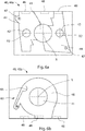
- the housing 40 can be made in one piece or from a plurality of housing halves 40a, 40b as a hybrid component, with a first housing half 40a in the Figure 6A is shown and the second housing half 40b in FIG Figure 6B . Both housing halves 40a, 40b have in common that they have a through opening 41 and each have at least one recess 44, 46 on an inner side.
- Both housing halves 40a, 40b have in common that they have a through opening 41 and each have at least one recess 44, 46 on an inner side.
- the first housing half 40a according to FIG Figure 6a are arranged on diametrical sides around the axis of rotation X2 bearing pin receptacles 42, which are adapted to the size of the bearing pin 24 of the pawls 20.
- the first recess 44 is formed around the journal receptacle 42, the first recess 44 being configured to receive the pawls 20.
- the recess 44 can be dimensioned such that the guide nose 25 of the respective pawl 20 protrudes.
- the shape and size of the first recess 44 take into account that the pawl 20 can be pivoted about the pivot axis X2 formed by the bearing pin receptacle 42 and the bearing pin 24.
- spring receptacles 47 can be provided, to each of which a return spring 27 can be attached.
- the second housing half 40b according to Figure 6b has the second recess 46, which is formed approximately coaxially to the through opening 41 and is adapted to the annular section of the coupling element 30.
- the annular section of the coupling element 30 can be mounted coaxially to the axis of rotation X, as a result of which the coupling element 30 is held so as to be rotatable about the axis of rotation X in the housing 40.
- the housing 40 can have one or more sensor pockets 48 on one side, which can accommodate a sensor 70.
- the sensor pockets 48 can be arranged both in the first housing half 40a and / or in the second housing half 40b and are shown with dotted lines in the Figures 6a and 6b indicated.
- the position securing device 60 which comprises a spring-loaded locking bracket 65 which is set up to engage in the recess 33 of the coupling element 30 in the first position A and / or in the second position B and to lock it.
- the adjusting device 50 can be any drive by means of which the coupling element 30 can be adjusted about the axis of rotation X from a first position A to a second position B.
- the actuating device 50 comprises a lifting magnet with two stable end positions, which is characterized in that a plunger 52 of the actuating device 50 is in a first end position, shown in FIG Figure 3 , to a second end position, shown in Figure 2 , can be held permanently magnetically.
- the plunger 52 has connecting means 54, by means of which an advancing movement can be transmitted to the coupling element 30.
- the actuating device 50 When the actuating device 50 is energized, the permanent magnetic holding force is released in the respective end position and the plunger is moved into the respective other end position.
- the lifting magnet enables a particularly rapid infeed of the actuating device 50.
- the adjusting device 50 via the connecting means 34, 54 can rotate the coupling element 30 from a first position A into a second position B about the axis of rotation X and vice versa.
- the respective guide nose 25 of the pawl 20 engages in the link guide 35 of the coupling element 30.
- the guide nose 25 of the pawl 20 is arranged in the first section 36 of the link guide 35.
- the return spring 27 biases the pawl 20 in the direction of the ratchet wheel 10.
- the guide nose 25 rests against the link guide 35 and the pawl 20 is pushed out of the ratchet wheel 10 against the bias of the restoring spring 27, which is why the ratchet teeth 26 cannot engage the ratchet wheel 10.
- the at least two pawls 20 release a rotation of the ratchet wheel 10 both in the first direction of rotation ⁇ 1 and in the second direction of rotation ⁇ 2.
- the respective guide nose 25 of the pawl 20 is arranged in the second section 37 of the link guide 35.
- the guide lug 25 is in the second section 37 of the link guide 35 in the radial direction - or around the pivot axis X2 - movable, and the respective pawl 20 can be pressed into the ratchet wheel 10 by a corresponding spring force of the return spring 27 or when rotated into the first rotation direction ⁇ 1 can be expressed by pressing on the tooth back.
- rotation is only possible in the first direction of rotation ⁇ 1, which is why in the second position B freewheeling, for example, tightening of the parking brake is possible. It is always possible to tighten the parking brake be necessary when the components involved in braking cool down after a journey and thermal expansion decreases. A release of the parking brake by turning in the second direction of rotation ⁇ 2 is blocked.
- the at least two pawls 20 are arranged in the direction of rotation around the axis of rotation X in such a way that they are alternately pressed in and out when the ratchet wheel 10 rotates in the first direction of rotation ⁇ 1.
- the pawls 20 are not arranged symmetrically to the toothing 12 with respect to the toothing 12 of the ratchet wheel 10, but are arranged offset by half a pitch angle ⁇ . This arrangement of the pawls 20 can ensure that in the second position B of the coupling element 30 one of the pawls 20 is always in engagement.
- a magnet 39 can be inserted into the pocket 38, which magnet interacts with a sensor 70, whereby it can be detected whether the coupling element 30 is in the first position A or the second position B.
- magnets 29 can be inserted into the pockets 28 of the pawls 20.
- the Figures 2 and 3 it can be seen that the magnet 29 is inserted into the pocket 28 of the pawl 20 on the left in the picture in the first end area. On the right in the picture, the magnet 29 is inserted into the pocket 28 in the second end area of the pawl. The magnets 29 of the two pawls thus point in the same spatial direction.
- the magnets 29 can interact with further sensors 70 to detect whether a pawl 20 engages the ratchet wheel 10 or not.
- the sensors 70 can, for example, Hall sensors which can detect a change in the magnetic field generated by the corresponding magnet 29, 39.
- the sensors 70 are arranged on one side of the housing. On this side of the housing, the sensors 70 can be arranged on a circuit board or the like. A controller can be provided on this printed circuit board, the controller being able to control both the actuating device 50 and the data from the sensors 70.
Landscapes
- Engineering & Computer Science (AREA)
- Mechanical Engineering (AREA)
- Transportation (AREA)
- General Engineering & Computer Science (AREA)
- Braking Arrangements (AREA)
- Braking Elements And Transmission Devices (AREA)
Priority Applications (5)
| Application Number | Priority Date | Filing Date | Title |
|---|---|---|---|
| ES20155686T ES2920828T3 (es) | 2020-02-05 | 2020-02-05 | Dispositivo de enclavamiento de un freno de estacionamiento y un freno de estacionamiento |
| EP20155686.7A EP3862235B1 (fr) | 2020-02-05 | 2020-02-05 | Dispositif de verrouillage d'un frein de stationnement et frein de stationnement |
| KR1020210011421A KR102500511B1 (ko) | 2020-02-05 | 2021-01-27 | 주차 브레이크의 잠금 장치 및 주차 브레이크 |
| CN202110143455.9A CN113291269B (zh) | 2020-02-05 | 2021-02-02 | 驻车制动器的锁定装置和驻车制动器 |
| US17/165,624 US11371607B2 (en) | 2020-02-05 | 2021-02-02 | Locking device of a parking brake and a parking brake |
Applications Claiming Priority (1)
| Application Number | Priority Date | Filing Date | Title |
|---|---|---|---|
| EP20155686.7A EP3862235B1 (fr) | 2020-02-05 | 2020-02-05 | Dispositif de verrouillage d'un frein de stationnement et frein de stationnement |
Publications (2)
| Publication Number | Publication Date |
|---|---|
| EP3862235A1 true EP3862235A1 (fr) | 2021-08-11 |
| EP3862235B1 EP3862235B1 (fr) | 2022-04-27 |
Family
ID=69500625
Family Applications (1)
| Application Number | Title | Priority Date | Filing Date |
|---|---|---|---|
| EP20155686.7A Active EP3862235B1 (fr) | 2020-02-05 | 2020-02-05 | Dispositif de verrouillage d'un frein de stationnement et frein de stationnement |
Country Status (5)
| Country | Link |
|---|---|
| US (1) | US11371607B2 (fr) |
| EP (1) | EP3862235B1 (fr) |
| KR (1) | KR102500511B1 (fr) |
| CN (1) | CN113291269B (fr) |
| ES (1) | ES2920828T3 (fr) |
Families Citing this family (5)
| Publication number | Priority date | Publication date | Assignee | Title |
|---|---|---|---|---|
| KR20220011483A (ko) * | 2020-07-21 | 2022-01-28 | 주식회사 만도 | 파킹 액츄에이터 및 이를 포함하는 전기 기계식 브레이크 |
| KR20220157750A (ko) * | 2021-05-21 | 2022-11-29 | 에이치엘만도 주식회사 | 전기 기계식 브레이크 시스템 및 그 제어방법 |
| US11506284B1 (en) * | 2021-05-24 | 2022-11-22 | Schaeffler Technologies AG & Co. KG | Multi-pawl park lock |
| TWI826958B (zh) * | 2022-03-16 | 2023-12-21 | 六和機械股份有限公司 | 車輛電子駐車裝置 |
| CN115199748B (zh) * | 2022-07-11 | 2023-09-05 | 东风汽车集团股份有限公司 | 一种液压控制驻车机构 |
Citations (2)
| Publication number | Priority date | Publication date | Assignee | Title |
|---|---|---|---|---|
| US20050258683A1 (en) * | 2004-05-19 | 2005-11-24 | Tohma Yamaguchi | Motor-driven disk brake system |
| US20100212461A1 (en) * | 2009-02-24 | 2010-08-26 | Burt William J | Open end ratchet wrench |
Family Cites Families (10)
| Publication number | Priority date | Publication date | Assignee | Title |
|---|---|---|---|---|
| US1450409A (en) * | 1921-07-19 | 1923-04-03 | Cirac Charles Paul | Reverse-movement control for driving and driven elements |
| US5605211A (en) * | 1995-10-20 | 1997-02-25 | General Motors Corporation | Park mechanism for a power transmission |
| CN201890218U (zh) * | 2010-12-03 | 2011-07-06 | 北汽福田汽车股份有限公司 | 一种驻车制动操纵装置 |
| KR101371906B1 (ko) * | 2012-12-28 | 2014-03-07 | 현대자동차주식회사 | 차량용 스크류 방식 전자 파킹 브레이크 |
| US9150214B2 (en) * | 2013-07-18 | 2015-10-06 | Fca Us Llc | Techniques for robust park lock control |
| DE102014103914A1 (de) * | 2014-03-21 | 2015-09-24 | Getrag Getriebe- Und Zahnradfabrik Hermann Hagenmeyer Gmbh & Cie Kg | Parksperrenanordnung für ein Kraftfahrzeuggetriebe |
| JP6152863B2 (ja) * | 2015-02-25 | 2017-06-28 | 株式会社アドヴィックス | 車両の電動制動装置 |
| CN105840820A (zh) * | 2016-05-24 | 2016-08-10 | 重庆海本液压机械制造有限公司 | 用于车辆变速器中的驻车锁止装置及其变速器 |
| US11149849B2 (en) * | 2017-05-10 | 2021-10-19 | Ka Group Ag | Linear actuator with safety mechanism |
| DE102018003752B4 (de) * | 2018-05-09 | 2023-04-13 | FTE automotive GmbH | Parksperrenmodul zur Betätigung einer Parksperre in einem Kraftfahrzeug |
-
2020
- 2020-02-05 ES ES20155686T patent/ES2920828T3/es active Active
- 2020-02-05 EP EP20155686.7A patent/EP3862235B1/fr active Active
-
2021
- 2021-01-27 KR KR1020210011421A patent/KR102500511B1/ko active IP Right Grant
- 2021-02-02 CN CN202110143455.9A patent/CN113291269B/zh active Active
- 2021-02-02 US US17/165,624 patent/US11371607B2/en active Active
Patent Citations (2)
| Publication number | Priority date | Publication date | Assignee | Title |
|---|---|---|---|---|
| US20050258683A1 (en) * | 2004-05-19 | 2005-11-24 | Tohma Yamaguchi | Motor-driven disk brake system |
| US20100212461A1 (en) * | 2009-02-24 | 2010-08-26 | Burt William J | Open end ratchet wrench |
Also Published As
| Publication number | Publication date |
|---|---|
| KR102500511B1 (ko) | 2023-02-16 |
| EP3862235B1 (fr) | 2022-04-27 |
| CN113291269A (zh) | 2021-08-24 |
| US20210239211A1 (en) | 2021-08-05 |
| KR20210100015A (ko) | 2021-08-13 |
| ES2920828T3 (es) | 2022-08-10 |
| CN113291269B (zh) | 2024-05-17 |
| US11371607B2 (en) | 2022-06-28 |
Similar Documents
| Publication | Publication Date | Title |
|---|---|---|
| EP3862235B1 (fr) | Dispositif de verrouillage d'un frein de stationnement et frein de stationnement | |
| DE69104464T2 (de) | Zylinderschloss. | |
| EP1110828B1 (fr) | Dispositif de verrouillage | |
| DE10320873B4 (de) | Bewegungsübertragungsvorrichtung und -verfahren | |
| DE102009017714A1 (de) | Lenkrad für ein Kraftfahrzeug mit Überlagerungslenkung | |
| EP2916045A1 (fr) | Système de frein de stationnement et boîte de vitesses de véhicule automobile | |
| EP1234733A2 (fr) | Dispositif pour le verrouillage sélectif de la colonne de direction d'un véhicule | |
| DE102010018243B4 (de) | Schließzylinderanordnung | |
| DE102015114078A1 (de) | Parksperrmechanismus | |
| DE102007059710B4 (de) | Kompakte Verriegelungsvorrichtung mit Sicherungselement | |
| DE102014108365A1 (de) | Schließvorrichtung, insbesondere Schloss | |
| DE102015207781A1 (de) | Lenkradschloss | |
| CH650054A5 (de) | Notschluesseleinrichtung an einem doppelzylinderschloss. | |
| EP2002142B1 (fr) | Frein de securite | |
| EP0721869A1 (fr) | Dispositif de verrouillage pour véhicules | |
| DE102007059712A1 (de) | Vorrichtung zur Ansteuerung eines Sperrgliedes | |
| DE102014219341B4 (de) | Parksperrenanordnung | |
| DE19921889A1 (de) | Zündschloß für ein Kraftfahrzeug | |
| DE102016015728A1 (de) | Parksperren-Aktuatoreinheit | |
| DE102014100719A1 (de) | Hinterachslenkung für Kraftfahrzeuge | |
| EP2078126B1 (fr) | Dispositif d'actionnement électromécanique pour battant ou analogue | |
| EP0943762A2 (fr) | Dispositif de verrouillage / deverrouillage avec une codage mécanique et électrique | |
| DE102021114493B4 (de) | Betätigungsaktuator für eine Parksperre | |
| EP2117887B1 (fr) | Dispositif d'asservissement d'un organe de blocage | |
| DE202016008250U1 (de) | Parksperren-Aktuatoreinheit |
Legal Events
| Date | Code | Title | Description |
|---|---|---|---|
| PUAI | Public reference made under article 153(3) epc to a published international application that has entered the european phase |
Free format text: ORIGINAL CODE: 0009012 |
|
| STAA | Information on the status of an ep patent application or granted ep patent |
Free format text: STATUS: THE APPLICATION HAS BEEN PUBLISHED |
|
| AK | Designated contracting states |
Kind code of ref document: A1 Designated state(s): AL AT BE BG CH CY CZ DE DK EE ES FI FR GB GR HR HU IE IS IT LI LT LU LV MC MK MT NL NO PL PT RO RS SE SI SK SM TR |
|
| STAA | Information on the status of an ep patent application or granted ep patent |
Free format text: STATUS: REQUEST FOR EXAMINATION WAS MADE |
|
| 17P | Request for examination filed |
Effective date: 20210927 |
|
| RBV | Designated contracting states (corrected) |
Designated state(s): AL AT BE BG CH CY CZ DE DK EE ES FI FR GB GR HR HU IE IS IT LI LT LU LV MC MK MT NL NO PL PT RO RS SE SI SK SM TR |
|
| GRAP | Despatch of communication of intention to grant a patent |
Free format text: ORIGINAL CODE: EPIDOSNIGR1 |
|
| STAA | Information on the status of an ep patent application or granted ep patent |
Free format text: STATUS: GRANT OF PATENT IS INTENDED |
|
| RIC1 | Information provided on ipc code assigned before grant |
Ipc: F16D 63/00 20060101ALI20211018BHEP Ipc: B60T 7/10 20060101ALI20211018BHEP Ipc: B60T 1/00 20060101AFI20211018BHEP |
|
| INTG | Intention to grant announced |
Effective date: 20211123 |
|
| GRAS | Grant fee paid |
Free format text: ORIGINAL CODE: EPIDOSNIGR3 |
|
| GRAA | (expected) grant |
Free format text: ORIGINAL CODE: 0009210 |
|
| STAA | Information on the status of an ep patent application or granted ep patent |
Free format text: STATUS: THE PATENT HAS BEEN GRANTED |
|
| AK | Designated contracting states |
Kind code of ref document: B1 Designated state(s): AL AT BE BG CH CY CZ DE DK EE ES FI FR GB GR HR HU IE IS IT LI LT LU LV MC MK MT NL NO PL PT RO RS SE SI SK SM TR |
|
| REG | Reference to a national code |
Ref country code: GB Ref legal event code: FG4D Free format text: NOT ENGLISH |
|
| REG | Reference to a national code |
Ref country code: CH Ref legal event code: EP |
|
| REG | Reference to a national code |
Ref country code: DE Ref legal event code: R096 Ref document number: 502020000984 Country of ref document: DE |
|
| REG | Reference to a national code |
Ref country code: AT Ref legal event code: REF Ref document number: 1486733 Country of ref document: AT Kind code of ref document: T Effective date: 20220515 |
|
| REG | Reference to a national code |
Ref country code: IE Ref legal event code: FG4D Free format text: LANGUAGE OF EP DOCUMENT: GERMAN |
|
| REG | Reference to a national code |
Ref country code: ES Ref legal event code: FG2A Ref document number: 2920828 Country of ref document: ES Kind code of ref document: T3 Effective date: 20220810 |
|
| REG | Reference to a national code |
Ref country code: LT Ref legal event code: MG9D |
|
| REG | Reference to a national code |
Ref country code: NL Ref legal event code: MP Effective date: 20220427 |
|
| PG25 | Lapsed in a contracting state [announced via postgrant information from national office to epo] |
Ref country code: NL Free format text: LAPSE BECAUSE OF FAILURE TO SUBMIT A TRANSLATION OF THE DESCRIPTION OR TO PAY THE FEE WITHIN THE PRESCRIBED TIME-LIMIT Effective date: 20220427 |
|
| PG25 | Lapsed in a contracting state [announced via postgrant information from national office to epo] |
Ref country code: SE Free format text: LAPSE BECAUSE OF FAILURE TO SUBMIT A TRANSLATION OF THE DESCRIPTION OR TO PAY THE FEE WITHIN THE PRESCRIBED TIME-LIMIT Effective date: 20220427 Ref country code: PT Free format text: LAPSE BECAUSE OF FAILURE TO SUBMIT A TRANSLATION OF THE DESCRIPTION OR TO PAY THE FEE WITHIN THE PRESCRIBED TIME-LIMIT Effective date: 20220829 Ref country code: NO Free format text: LAPSE BECAUSE OF FAILURE TO SUBMIT A TRANSLATION OF THE DESCRIPTION OR TO PAY THE FEE WITHIN THE PRESCRIBED TIME-LIMIT Effective date: 20220727 Ref country code: LT Free format text: LAPSE BECAUSE OF FAILURE TO SUBMIT A TRANSLATION OF THE DESCRIPTION OR TO PAY THE FEE WITHIN THE PRESCRIBED TIME-LIMIT Effective date: 20220427 Ref country code: HR Free format text: LAPSE BECAUSE OF FAILURE TO SUBMIT A TRANSLATION OF THE DESCRIPTION OR TO PAY THE FEE WITHIN THE PRESCRIBED TIME-LIMIT Effective date: 20220427 Ref country code: GR Free format text: LAPSE BECAUSE OF FAILURE TO SUBMIT A TRANSLATION OF THE DESCRIPTION OR TO PAY THE FEE WITHIN THE PRESCRIBED TIME-LIMIT Effective date: 20220728 Ref country code: FI Free format text: LAPSE BECAUSE OF FAILURE TO SUBMIT A TRANSLATION OF THE DESCRIPTION OR TO PAY THE FEE WITHIN THE PRESCRIBED TIME-LIMIT Effective date: 20220427 Ref country code: BG Free format text: LAPSE BECAUSE OF FAILURE TO SUBMIT A TRANSLATION OF THE DESCRIPTION OR TO PAY THE FEE WITHIN THE PRESCRIBED TIME-LIMIT Effective date: 20220727 |
|
| PG25 | Lapsed in a contracting state [announced via postgrant information from national office to epo] |
Ref country code: RS Free format text: LAPSE BECAUSE OF FAILURE TO SUBMIT A TRANSLATION OF THE DESCRIPTION OR TO PAY THE FEE WITHIN THE PRESCRIBED TIME-LIMIT Effective date: 20220427 Ref country code: PL Free format text: LAPSE BECAUSE OF FAILURE TO SUBMIT A TRANSLATION OF THE DESCRIPTION OR TO PAY THE FEE WITHIN THE PRESCRIBED TIME-LIMIT Effective date: 20220427 Ref country code: LV Free format text: LAPSE BECAUSE OF FAILURE TO SUBMIT A TRANSLATION OF THE DESCRIPTION OR TO PAY THE FEE WITHIN THE PRESCRIBED TIME-LIMIT Effective date: 20220427 Ref country code: IS Free format text: LAPSE BECAUSE OF FAILURE TO SUBMIT A TRANSLATION OF THE DESCRIPTION OR TO PAY THE FEE WITHIN THE PRESCRIBED TIME-LIMIT Effective date: 20220827 |
|
| REG | Reference to a national code |
Ref country code: DE Ref legal event code: R097 Ref document number: 502020000984 Country of ref document: DE |
|
| PG25 | Lapsed in a contracting state [announced via postgrant information from national office to epo] |
Ref country code: SM Free format text: LAPSE BECAUSE OF FAILURE TO SUBMIT A TRANSLATION OF THE DESCRIPTION OR TO PAY THE FEE WITHIN THE PRESCRIBED TIME-LIMIT Effective date: 20220427 Ref country code: SK Free format text: LAPSE BECAUSE OF FAILURE TO SUBMIT A TRANSLATION OF THE DESCRIPTION OR TO PAY THE FEE WITHIN THE PRESCRIBED TIME-LIMIT Effective date: 20220427 Ref country code: RO Free format text: LAPSE BECAUSE OF FAILURE TO SUBMIT A TRANSLATION OF THE DESCRIPTION OR TO PAY THE FEE WITHIN THE PRESCRIBED TIME-LIMIT Effective date: 20220427 Ref country code: EE Free format text: LAPSE BECAUSE OF FAILURE TO SUBMIT A TRANSLATION OF THE DESCRIPTION OR TO PAY THE FEE WITHIN THE PRESCRIBED TIME-LIMIT Effective date: 20220427 Ref country code: DK Free format text: LAPSE BECAUSE OF FAILURE TO SUBMIT A TRANSLATION OF THE DESCRIPTION OR TO PAY THE FEE WITHIN THE PRESCRIBED TIME-LIMIT Effective date: 20220427 Ref country code: CZ Free format text: LAPSE BECAUSE OF FAILURE TO SUBMIT A TRANSLATION OF THE DESCRIPTION OR TO PAY THE FEE WITHIN THE PRESCRIBED TIME-LIMIT Effective date: 20220427 |
|
| PLBE | No opposition filed within time limit |
Free format text: ORIGINAL CODE: 0009261 |
|
| STAA | Information on the status of an ep patent application or granted ep patent |
Free format text: STATUS: NO OPPOSITION FILED WITHIN TIME LIMIT |
|
| PG25 | Lapsed in a contracting state [announced via postgrant information from national office to epo] |
Ref country code: AL Free format text: LAPSE BECAUSE OF FAILURE TO SUBMIT A TRANSLATION OF THE DESCRIPTION OR TO PAY THE FEE WITHIN THE PRESCRIBED TIME-LIMIT Effective date: 20220427 |
|
| 26N | No opposition filed |
Effective date: 20230130 |
|
| P01 | Opt-out of the competence of the unified patent court (upc) registered |
Effective date: 20230323 |
|
| PG25 | Lapsed in a contracting state [announced via postgrant information from national office to epo] |
Ref country code: MC Free format text: LAPSE BECAUSE OF FAILURE TO SUBMIT A TRANSLATION OF THE DESCRIPTION OR TO PAY THE FEE WITHIN THE PRESCRIBED TIME-LIMIT Effective date: 20220427 |
|
| REG | Reference to a national code |
Ref country code: CH Ref legal event code: PL |
|
| REG | Reference to a national code |
Ref country code: BE Ref legal event code: MM Effective date: 20230228 |
|
| PG25 | Lapsed in a contracting state [announced via postgrant information from national office to epo] |
Ref country code: LU Free format text: LAPSE BECAUSE OF NON-PAYMENT OF DUE FEES Effective date: 20230205 Ref country code: LI Free format text: LAPSE BECAUSE OF NON-PAYMENT OF DUE FEES Effective date: 20230228 Ref country code: CH Free format text: LAPSE BECAUSE OF NON-PAYMENT OF DUE FEES Effective date: 20230228 |
|
| REG | Reference to a national code |
Ref country code: IE Ref legal event code: MM4A |
|
| PG25 | Lapsed in a contracting state [announced via postgrant information from national office to epo] |
Ref country code: IE Free format text: LAPSE BECAUSE OF NON-PAYMENT OF DUE FEES Effective date: 20230205 |
|
| PG25 | Lapsed in a contracting state [announced via postgrant information from national office to epo] |
Ref country code: BE Free format text: LAPSE BECAUSE OF NON-PAYMENT OF DUE FEES Effective date: 20230228 |
|
| PGFP | Annual fee paid to national office [announced via postgrant information from national office to epo] |
Ref country code: ES Payment date: 20240319 Year of fee payment: 5 |
|
| PGFP | Annual fee paid to national office [announced via postgrant information from national office to epo] |
Ref country code: DE Payment date: 20240319 Year of fee payment: 5 |
|
| PGFP | Annual fee paid to national office [announced via postgrant information from national office to epo] |
Ref country code: IT Payment date: 20240222 Year of fee payment: 5 Ref country code: FR Payment date: 20240220 Year of fee payment: 5 |