EP3859246B1 - Kühlsystem - Google Patents
Kühlsystem Download PDFInfo
- Publication number
- EP3859246B1 EP3859246B1 EP20275023.8A EP20275023A EP3859246B1 EP 3859246 B1 EP3859246 B1 EP 3859246B1 EP 20275023 A EP20275023 A EP 20275023A EP 3859246 B1 EP3859246 B1 EP 3859246B1
- Authority
- EP
- European Patent Office
- Prior art keywords
- pressure
- heat exchanger
- refrigeration system
- measured
- controller
- Prior art date
- Legal status (The legal status is an assumption and is not a legal conclusion. Google has not performed a legal analysis and makes no representation as to the accuracy of the status listed.)
- Active
Links
- 238000005057 refrigeration Methods 0.000 title claims description 54
- 239000003507 refrigerant Substances 0.000 claims description 21
- 239000012530 fluid Substances 0.000 claims description 14
- 238000000034 method Methods 0.000 claims description 13
- 230000006835 compression Effects 0.000 claims description 8
- 238000007906 compression Methods 0.000 claims description 8
- 238000001816 cooling Methods 0.000 description 4
- 238000009530 blood pressure measurement Methods 0.000 description 3
- 238000010586 diagram Methods 0.000 description 3
- 238000010438 heat treatment Methods 0.000 description 3
- 239000007788 liquid Substances 0.000 description 3
- 238000005406 washing Methods 0.000 description 3
- 230000000694 effects Effects 0.000 description 2
- 239000000203 mixture Substances 0.000 description 2
- 238000004364 calculation method Methods 0.000 description 1
- 238000011109 contamination Methods 0.000 description 1
- 230000001419 dependent effect Effects 0.000 description 1
- 230000000368 destabilizing effect Effects 0.000 description 1
- 238000001704 evaporation Methods 0.000 description 1
- 238000011010 flushing procedure Methods 0.000 description 1
- 229920006395 saturated elastomer Polymers 0.000 description 1
- 238000009491 slugging Methods 0.000 description 1
Images

Classifications
-
- F—MECHANICAL ENGINEERING; LIGHTING; HEATING; WEAPONS; BLASTING
- F25—REFRIGERATION OR COOLING; COMBINED HEATING AND REFRIGERATION SYSTEMS; HEAT PUMP SYSTEMS; MANUFACTURE OR STORAGE OF ICE; LIQUEFACTION SOLIDIFICATION OF GASES
- F25B—REFRIGERATION MACHINES, PLANTS OR SYSTEMS; COMBINED HEATING AND REFRIGERATION SYSTEMS; HEAT PUMP SYSTEMS
- F25B49/00—Arrangement or mounting of control or safety devices
- F25B49/005—Arrangement or mounting of control or safety devices of safety devices
-
- F—MECHANICAL ENGINEERING; LIGHTING; HEATING; WEAPONS; BLASTING
- F25—REFRIGERATION OR COOLING; COMBINED HEATING AND REFRIGERATION SYSTEMS; HEAT PUMP SYSTEMS; MANUFACTURE OR STORAGE OF ICE; LIQUEFACTION SOLIDIFICATION OF GASES
- F25B—REFRIGERATION MACHINES, PLANTS OR SYSTEMS; COMBINED HEATING AND REFRIGERATION SYSTEMS; HEAT PUMP SYSTEMS
- F25B1/00—Compression machines, plants or systems with non-reversible cycle
-
- F—MECHANICAL ENGINEERING; LIGHTING; HEATING; WEAPONS; BLASTING
- F24—HEATING; RANGES; VENTILATING
- F24F—AIR-CONDITIONING; AIR-HUMIDIFICATION; VENTILATION; USE OF AIR CURRENTS FOR SCREENING
- F24F11/00—Control or safety arrangements
- F24F11/30—Control or safety arrangements for purposes related to the operation of the system, e.g. for safety or monitoring
- F24F11/49—Control or safety arrangements for purposes related to the operation of the system, e.g. for safety or monitoring ensuring correct operation, e.g. by trial operation or configuration checks
-
- F—MECHANICAL ENGINEERING; LIGHTING; HEATING; WEAPONS; BLASTING
- F24—HEATING; RANGES; VENTILATING
- F24F—AIR-CONDITIONING; AIR-HUMIDIFICATION; VENTILATION; USE OF AIR CURRENTS FOR SCREENING
- F24F11/00—Control or safety arrangements
- F24F11/62—Control or safety arrangements characterised by the type of control or by internal processing, e.g. using fuzzy logic, adaptive control or estimation of values
- F24F11/63—Electronic processing
- F24F11/64—Electronic processing using pre-stored data
-
- F—MECHANICAL ENGINEERING; LIGHTING; HEATING; WEAPONS; BLASTING
- F24—HEATING; RANGES; VENTILATING
- F24F—AIR-CONDITIONING; AIR-HUMIDIFICATION; VENTILATION; USE OF AIR CURRENTS FOR SCREENING
- F24F11/00—Control or safety arrangements
- F24F11/62—Control or safety arrangements characterised by the type of control or by internal processing, e.g. using fuzzy logic, adaptive control or estimation of values
- F24F11/63—Electronic processing
- F24F11/65—Electronic processing for selecting an operating mode
-
- F—MECHANICAL ENGINEERING; LIGHTING; HEATING; WEAPONS; BLASTING
- F25—REFRIGERATION OR COOLING; COMBINED HEATING AND REFRIGERATION SYSTEMS; HEAT PUMP SYSTEMS; MANUFACTURE OR STORAGE OF ICE; LIQUEFACTION SOLIDIFICATION OF GASES
- F25B—REFRIGERATION MACHINES, PLANTS OR SYSTEMS; COMBINED HEATING AND REFRIGERATION SYSTEMS; HEAT PUMP SYSTEMS
- F25B41/00—Fluid-circulation arrangements
- F25B41/30—Expansion means; Dispositions thereof
- F25B41/31—Expansion valves
- F25B41/33—Expansion valves with the valve member being actuated by the fluid pressure, e.g. by the pressure of the refrigerant
-
- F—MECHANICAL ENGINEERING; LIGHTING; HEATING; WEAPONS; BLASTING
- F25—REFRIGERATION OR COOLING; COMBINED HEATING AND REFRIGERATION SYSTEMS; HEAT PUMP SYSTEMS; MANUFACTURE OR STORAGE OF ICE; LIQUEFACTION SOLIDIFICATION OF GASES
- F25B—REFRIGERATION MACHINES, PLANTS OR SYSTEMS; COMBINED HEATING AND REFRIGERATION SYSTEMS; HEAT PUMP SYSTEMS
- F25B49/00—Arrangement or mounting of control or safety devices
- F25B49/02—Arrangement or mounting of control or safety devices for compression type machines, plants or systems
-
- G—PHYSICS
- G05—CONTROLLING; REGULATING
- G05B—CONTROL OR REGULATING SYSTEMS IN GENERAL; FUNCTIONAL ELEMENTS OF SUCH SYSTEMS; MONITORING OR TESTING ARRANGEMENTS FOR SUCH SYSTEMS OR ELEMENTS
- G05B13/00—Adaptive control systems, i.e. systems automatically adjusting themselves to have a performance which is optimum according to some preassigned criterion
- G05B13/02—Adaptive control systems, i.e. systems automatically adjusting themselves to have a performance which is optimum according to some preassigned criterion electric
- G05B13/0205—Adaptive control systems, i.e. systems automatically adjusting themselves to have a performance which is optimum according to some preassigned criterion electric not using a model or a simulator of the controlled system
- G05B13/026—Adaptive control systems, i.e. systems automatically adjusting themselves to have a performance which is optimum according to some preassigned criterion electric not using a model or a simulator of the controlled system using a predictor
-
- F—MECHANICAL ENGINEERING; LIGHTING; HEATING; WEAPONS; BLASTING
- F24—HEATING; RANGES; VENTILATING
- F24F—AIR-CONDITIONING; AIR-HUMIDIFICATION; VENTILATION; USE OF AIR CURRENTS FOR SCREENING
- F24F2110/00—Control inputs relating to air properties
- F24F2110/10—Temperature
-
- F—MECHANICAL ENGINEERING; LIGHTING; HEATING; WEAPONS; BLASTING
- F24—HEATING; RANGES; VENTILATING
- F24F—AIR-CONDITIONING; AIR-HUMIDIFICATION; VENTILATION; USE OF AIR CURRENTS FOR SCREENING
- F24F2110/00—Control inputs relating to air properties
- F24F2110/10—Temperature
- F24F2110/12—Temperature of the outside air
-
- F—MECHANICAL ENGINEERING; LIGHTING; HEATING; WEAPONS; BLASTING
- F25—REFRIGERATION OR COOLING; COMBINED HEATING AND REFRIGERATION SYSTEMS; HEAT PUMP SYSTEMS; MANUFACTURE OR STORAGE OF ICE; LIQUEFACTION SOLIDIFICATION OF GASES
- F25B—REFRIGERATION MACHINES, PLANTS OR SYSTEMS; COMBINED HEATING AND REFRIGERATION SYSTEMS; HEAT PUMP SYSTEMS
- F25B2341/00—Details of ejectors not being used as compression device; Details of flow restrictors or expansion valves
- F25B2341/06—Details of flow restrictors or expansion valves
- F25B2341/063—Feed forward expansion valves
-
- F—MECHANICAL ENGINEERING; LIGHTING; HEATING; WEAPONS; BLASTING
- F25—REFRIGERATION OR COOLING; COMBINED HEATING AND REFRIGERATION SYSTEMS; HEAT PUMP SYSTEMS; MANUFACTURE OR STORAGE OF ICE; LIQUEFACTION SOLIDIFICATION OF GASES
- F25B—REFRIGERATION MACHINES, PLANTS OR SYSTEMS; COMBINED HEATING AND REFRIGERATION SYSTEMS; HEAT PUMP SYSTEMS
- F25B2500/00—Problems to be solved
- F25B2500/07—Exceeding a certain pressure value in a refrigeration component or cycle
-
- F—MECHANICAL ENGINEERING; LIGHTING; HEATING; WEAPONS; BLASTING
- F25—REFRIGERATION OR COOLING; COMBINED HEATING AND REFRIGERATION SYSTEMS; HEAT PUMP SYSTEMS; MANUFACTURE OR STORAGE OF ICE; LIQUEFACTION SOLIDIFICATION OF GASES
- F25B—REFRIGERATION MACHINES, PLANTS OR SYSTEMS; COMBINED HEATING AND REFRIGERATION SYSTEMS; HEAT PUMP SYSTEMS
- F25B2600/00—Control issues
- F25B2600/25—Control of valves
- F25B2600/2513—Expansion valves
-
- F—MECHANICAL ENGINEERING; LIGHTING; HEATING; WEAPONS; BLASTING
- F25—REFRIGERATION OR COOLING; COMBINED HEATING AND REFRIGERATION SYSTEMS; HEAT PUMP SYSTEMS; MANUFACTURE OR STORAGE OF ICE; LIQUEFACTION SOLIDIFICATION OF GASES
- F25B—REFRIGERATION MACHINES, PLANTS OR SYSTEMS; COMBINED HEATING AND REFRIGERATION SYSTEMS; HEAT PUMP SYSTEMS
- F25B2700/00—Sensing or detecting of parameters; Sensors therefor
- F25B2700/19—Pressures
- F25B2700/193—Pressures of the compressor
- F25B2700/1931—Discharge pressures
-
- F—MECHANICAL ENGINEERING; LIGHTING; HEATING; WEAPONS; BLASTING
- F25—REFRIGERATION OR COOLING; COMBINED HEATING AND REFRIGERATION SYSTEMS; HEAT PUMP SYSTEMS; MANUFACTURE OR STORAGE OF ICE; LIQUEFACTION SOLIDIFICATION OF GASES
- F25B—REFRIGERATION MACHINES, PLANTS OR SYSTEMS; COMBINED HEATING AND REFRIGERATION SYSTEMS; HEAT PUMP SYSTEMS
- F25B2700/00—Sensing or detecting of parameters; Sensors therefor
- F25B2700/19—Pressures
- F25B2700/195—Pressures of the condenser
-
- Y—GENERAL TAGGING OF NEW TECHNOLOGICAL DEVELOPMENTS; GENERAL TAGGING OF CROSS-SECTIONAL TECHNOLOGIES SPANNING OVER SEVERAL SECTIONS OF THE IPC; TECHNICAL SUBJECTS COVERED BY FORMER USPC CROSS-REFERENCE ART COLLECTIONS [XRACs] AND DIGESTS
- Y02—TECHNOLOGIES OR APPLICATIONS FOR MITIGATION OR ADAPTATION AGAINST CLIMATE CHANGE
- Y02B—CLIMATE CHANGE MITIGATION TECHNOLOGIES RELATED TO BUILDINGS, e.g. HOUSING, HOUSE APPLIANCES OR RELATED END-USER APPLICATIONS
- Y02B30/00—Energy efficient heating, ventilation or air conditioning [HVAC]
- Y02B30/70—Efficient control or regulation technologies, e.g. for control of refrigerant flow, motor or heating
Definitions
- the present invention relates to a refrigeration system and a method of operating a refrigeration system.
- Refrigeration or heating can be provided by a refrigeration system making use of the refrigeration cycle, in which a refrigerant fluid is compressed, cooled, expanded and then heated.
- the cooling of the refrigerant fluid may be done via a heat rejecting heat exchanger rejecting heat to the atmosphere
- the heating of the refrigerant fluid may be done via a heat absorbing heat exchanger absorbing heat from an object to be cooled, such as a refrigerated space for low temperature storage, or an interior of a building.
- the refrigeration system can transfer heat from within the refrigerated space or building to outside of the refrigerated space or building, even when the interior is cooler than the atmosphere.
- a refrigeration system can be used as a heat pump to satisfy a heat demand.
- the heat absorbing heat exchanger may be used to absorb heat from a low temperature source, with the refrigeration circuit then rejecting heat to a higher temperature object that is to be heated.
- this may be, for example, the interior of a building.
- US 10107533B2 discloses a refrigerant system according to the preamble of claim 1 and a method according to the preamble of claim 7; wherein a controller of said refrigeration system is configured to perform method steps for a pressure spike reduction.
- the present invention provides a refrigeration system according to claim 1; and a method according to claim 7. Further preferred embodiments of the invention are defined in the dependent claims.
- a refrigeration system includes a compression device 12, a heat rejecting heat exchanger 14, an expansion device 18 and a heat absorbing heat exchanger 16 that together form a refrigeration circuit.
- the refrigeration circuit contains a refrigerant fluid and circulation of the refrigerant fluid via the compression device 12 enables the refrigeration system to utilise a refrigeration cycle (or heat pump cycle) to satisfy a cooling (or heating) load.
- the compression device 12 is a compressor 12 for compression of gaseous refrigerant fluid
- the heat rejecting heat exchanger 14 is a condenser for at least partially condensing the refrigerant fluid
- the expansion device 18 is an expansion valve for expanding the refrigerant fluid
- the heat absorbing heat exchanger 16 is an evaporator for at least partially evaporating the refrigerant fluid.
- the refrigeration system may be arranged so that the fluid is fully condensed at the condenser 14, and fully evaporated at the evaporator 16.
- the system also includes a controller 20 which may receive various inputs from the refrigeration system, and which may be configured to control various parts of the refrigeration system.
- the controller may comprise suitable control circuitry that is configured to cause the refrigeration system to operate in the manner of the various embodiments described herein.
- the controller may comprise suitable processing circuitry configured to perform any one or more or all of the necessary processing operations in respect of the various embodiments described herein.
- the controller may comprise a suitable computing device (computer), a microprocessor system, a programmable FPGA (field programmable gate array), and the like.
- the controller 20 receives as an input a pressure measurement from a pressure sensor 22 arranged at the inlet to the heat rejecting heat exchanger 14.
- the controller is configured to receive other inputs from the refrigeration system (not shown in Figure 1 ), as will be described further below.
- the controller is also configured to control the expansion device 18 by controlling a degree of opening of the expansion valve.
- the controller may be configured to control other elements of the refrigeration system (not shown in Figure 1 ).
- the heat rejecting heat exchanger 14 may comprise a micro-channel heat exchanger (MCHE). Typically these heat exchangers have been operated with R410A or R134a refrigerant.
- MCHE micro-channel heat exchanger
- a liquid slug (or "slug flow") phenomenon of refrigerant fluid within the heat rejecting heat exchanger 14 can be responsible for destabilizing the refrigeration system, thereby reducing the conditions under which the system can reliably operate, and reducing its efficiency. This is thought to be due to the new refrigerant/oil mixture having a lower refrigerant density, but a higher oil viscosity.
- a similar phenomenon may also occur when other high pressure refrigerants (such as R32, R410A, R454B etc.) are used in together with a micro-channel heat exchanger (MCHE).
- MCHE micro-channel heat exchanger
- Figure 2 is a graph showing pressure measured by the sensor 22 as a function of time in a refrigeration system not according to the invention operated without controlling the expansion device 18 on the basis of the comparison in the manner of various embodiments.
- Figure 2 also shows the degree of opening of the expansion valve 18 as a function of time.
- the system is initially operated in a "normal" state, whereby the expansion valve 18 is operated with a desired degree of opening, in this example of around 7%.
- slug flow has occurred within the heat rejecting heat exchanger 14, and so the pressure measured by the sensor 22 rises with time until a maximum permitted operating pressure is reached.
- the controller 20 causes the refrigeration system to shut down by closing the expansion device 18 completely.
- the disadvantageously causes disruption to the user, as the system ceases to operate due to the controller 20 shutting down the system when the system is operating at a dangerously high pressure.
- the controller 20 is provided with additional logic in order to eliminate or reduce problems associated with slug flow.
- the controller 20 is configured to calculate a maximum pressure value that is expected to be measured by the sensor 22 absent the slug flow phenomenon. This calculation is done using operating parameters of the refrigeration system (other than the measured pressure) that can be readily measured and/or determined. A measured pressure reaching or exceeding this predicted pressure can be indicative of the presence of slug flow (or similar instabilities).
- suitable predicted maximum pressure value can be determined based on the outdoor air temperature, evaporator temperature, compressor tonnage, heat exchanger area, pressure ratio and fan rotation speed.
- the "Tons per coil” may be the number of compressors switched on divided by the number of coils of the circuit;
- OAT may be the outdoor air temperature (which may be measured by a temperature sensor);
- SST may be the saturated suction temperature of the circuit (which may be measured by a pressure sensor, for example on the suction pipe);
- P discharge /P suction may be the ratio of the discharge pressure and suction pressure of the circuit (which may be measured by pressure sensors, e.g. on the discharge and suction pipe);
- “Rpm fan” may be the fan frequency of the circuit (which may be determined from software). It should be noted that all of these parameters can be measured or determined using sensors that may already be present within the refrigeration system, so that no additional sensors may be needed.
- the various coefficients a, b, c, d and e may be set as desired for the particular refrigeration system in question, e.g. depending on a calibration and/or changing operating conditions. For example, they may be set so as to take into account contamination of the coil(s), etc.
- the controller 20 is configured to compare the pressure measured by the sensor 22 to the calculated predicted pressure value.
- the controller 20 may control the expansion valve 18 so as to increase its degree of opening, so as to momentarily increase the mass flow rate of refrigerant through the refrigeration circuit, thereby reducing the pressure within the heat rejecting heat exchanger 14 and stopping or reducing slug flow within the heat rejecting heat exchanger 14.
- the controller 20 may control the expansion valve 18 so as to increase its degree of opening for a sufficiently short period of time and at a sufficiently low degree of opening such that the effect of the pressure wave is insignificant on the operation of the refrigeration system, meaning it is not detectable by the user.
- Figure 3 is a flow diagram illustrating the controller's 20 programmed logic for controlling the expansion valve 18.
- the controller receives information indicative of the pressure ("discharge pressure") measured by the sensor 22.
- the pressure measurement is compared to a maximum system pressure, which is calculated using the equation described above.
- the controller 20 may be configured to receive readings from the sensor 22 continuously or periodically, to calculate the maximum system pressure continuously or periodically, and to compare the measured value to the maximum system pressure continuously or periodically.
- the controller 20 activates its "washing coils logic" by opening the expansion valve 18 for a specific amount of time and at a specific degree of opening, thereby eliminating any slug flow from the system.
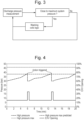
- Figure 4 is a graph showing the pressure measured by the sensor 22 as a function of time in a refrigeration system operated when controlling the expansion device 18 on the basis of the comparison in the manner of various embodiments.
- the system is initially operated in a "normal" state, whereby the expansion valve 18 is operated with a desired degree of opening, in this example of around 7%.
- slug flow has occurred within the heat rejecting heat exchanger 14, and so the pressure measured by the sensor 22 rises with time.
- the system continuously calculates a maximum pressure in the manner described above. Once the measured pressure reaches or exceeds the calculated maximum pressure, the degree of opening of the expansion valve 18 is increased for a short amount of time (a few seconds or tens of seconds) and at a specific opening percentage (in this example around 18 %), thereby reducing the pressure of the refrigerant fluid within the heat rejecting heat exchanger 14, and eliminating and/or removing any slug flow.
- This process is repeated continuously during the operation of the refrigeration system, so that the pressure does not ever reach the maximum permitted operating pressure.
- a low proportion of liquid slugging can provide a higher efficiency by producing additional sub-cooling.
- Efficiency gains at low load condition are estimated at up to 5%.
- various embodiments provide an algorithm that can detect a slug flow phenomenon and can act to ensure stable operation at various possible operating conditions.
- the pressure of the heat exchanger 14 is continuously monitored, and a theoretical coil pressure is continuously evaluated.
- the washing coil logic involves opening the expansion device 18 for a specific time duration and opening position in order to wash the coils of the heat exchanger 14 by flushing the liquid mixture for a few seconds, thereby significantly increasing the refrigerant flow.
- Various embodiments advantageously provide more stable operation of the system without any visible effects on the refrigeration provided, broaden the operating envelop of the system, and improve its efficiency.
Landscapes
- Engineering & Computer Science (AREA)
- Physics & Mathematics (AREA)
- Mechanical Engineering (AREA)
- General Engineering & Computer Science (AREA)
- Thermal Sciences (AREA)
- Signal Processing (AREA)
- Chemical & Material Sciences (AREA)
- Combustion & Propulsion (AREA)
- Fuzzy Systems (AREA)
- Mathematical Physics (AREA)
- Health & Medical Sciences (AREA)
- Artificial Intelligence (AREA)
- Computer Vision & Pattern Recognition (AREA)
- Evolutionary Computation (AREA)
- Medical Informatics (AREA)
- Software Systems (AREA)
- General Physics & Mathematics (AREA)
- Automation & Control Theory (AREA)
- Fluid Mechanics (AREA)
- Air Conditioning Control Device (AREA)
- Devices That Are Associated With Refrigeration Equipment (AREA)
- Compression-Type Refrigeration Machines With Reversible Cycles (AREA)
Claims (11)
- Kühlsystem, umfassend:einen Kühlkreis, der eine Kompressionsvorrichtung (12), einen wärmeabführenden Wärmetauscher (14), eine Expansionsvorrichtung (18) und einen wärmeabsorbierenden Wärmetauscher (16) umfasst;einen oder mehrere Sensoren (22), die konfiguriert sind, um einen Druck zu messen, der dem wärmeabführenden Wärmetauscher (14) zugeordnet ist; undeine Steuereinheit (20), die konfiguriert ist, um den von dem einen oder den mehreren Sensoren (22) gemessenen Druck mit einem vorhergesagten Druck zu vergleichen und die Expansionsvorrichtung (18) auf der Grundlage des Vergleichs zu steuern; dadurch gekennzeichnet, dass:die Steuereinheit (20) konfiguriert ist, um den vorhergesagten Druck unter Verwendung von einem oder mehreren gemessenen Parametern kontinuierlich und/oder regelmäßig zu berechnen;wobei der eine oder die mehreren gemessenen Parametern Folgendes umfassen: (i) eine Außenlufttemperatur; (ii) eine Temperatur, die dem wärmeabsorbierenden Wärmetauscher zugeordnet ist; (iii) eine Kapazität der Kompressionsvorrichtung; (iv) eine Fläche, die dem wärmeabführenden Wärmetauscher zugeordnet ist; (v) ein Druckverhältnis, das dem Kühlkreis zugeordnet ist; und/oder (vi) eine Gebläsegeschwindigkeit, die dem Kühlkreis zugeordnet ist; undwobei der vorhergesagte Druck ein maximaler vorhergesagter Druck einer Kältemittelflüssigkeit bei nicht vorliegendem Schallströmungsphänomen ist.
- Kühlsystem nach Anspruch 1, wobei die Steuereinheit (20) konfiguriert ist, um den gemessenen Druck kontinuierlich und/oder regelmäßig mit dem vorhergesagten Druck zu vergleichen.
- Kühlsystem nach Anspruch 1 oder 2, wobei die Expansionsvorrichtung (18) ein Entspannungsventil umfasst, und wobei die Steuereinheit (20) konfiguriert ist, um einen Öffnungsgrad des Entspannungsventils auf der Grundlage des Vergleichs zu steuern.
- Kühlsystem nach Anspruch 3, wobei die Steuereinheit (20) konfiguriert ist, um die Expansionsvorrichtung (18) auf der Grundlage des Vergleichs durch vorübergehendes Erhöhen des Öffnungsgrads des Entspannungsventils zu steuern, wenn der gemessene Druck größer als oder gleich groß wie der vorhergesagte Druck ist.
- Kühlsystem nach Anspruch 4, wobei die Steuereinheit (20) konfiguriert ist, um den Öffnungsgrad des Entspannungsventils um einen Faktor von etwa (i) ≥ 1,5; (ii) ≥ 2; (iii) > 2,5; (iv) > 3; (v) > 3,5; oder (vi) > 4 vorübergehend zu erhöhen.
- Kühlsystem nach Anspruch 4 oder 5, wobei die Steuereinheit (20) konfiguriert ist, um den Öffnungsgrad des Entspannungsventils für eine Zeitdauer von etwa (i) 1 - 10 s; (ii) 10 - 20 s; (iii) 20 - 30 s; (iv) 30 - 40 s; (v) 40 - 50 s; (vi) 50 - 60 s; oder (vii) > 60 s vorübergehend zu erhöhen.
- Verfahren zum Betreiben eines Kühlsystems, das einen Kühlkreis umfasst, der eine Kompressionsvorrichtung (12), einen wärmeabführenden Wärmetauscher (14), eine Expansionsvorrichtung (18) und einen wärmeabsorbierenden Wärmetauscher (16) umfasst, wobei das Verfahren Folgendes umfasst:Messen eines Drucks, der dem wärmeabführenden Wärmetauscher (14) zugeordnet ist;Vergleichen des gemessenen Drucks mit einem vorhergesagten Druck; undSteuern der Expansionsvorrichtung (18) auf der Grundlage des Vergleichs; wobei das Verfahren gekennzeichnet ist durch:kontinuierliches und/oder regelmäßiges Messen von einem oder mehreren Parametern;kontinuierliches und/oder regelmäßiges Berechnen des vorhergesagten Drucks basierend auf dem einen oder den mehreren Parametern;wobei der eine oder die mehreren gemessenen Parametern Folgendes umfassen: (i) eine Außenlufttemperatur; (ii) eine Temperatur, die dem wärmeabsorbierenden Wärmetauscher zugeordnet ist; (iii) eine Kapazität der Kompressionsvorrichtung; (iv) eine Fläche, die dem wärmeabführenden Wärmetauscher zugeordnet ist; (v) ein Druckverhältnis, das dem Kühlkreis zugeordnet ist; und/oder (vi) eine Gebläsegeschwindigkeit, die dem Kühlkreis zugeordnet ist; undwobei der vorhergesagte Druck ein maximaler vorhergesagter Druck einer Kältemittelflüssigkeit bei nicht vorliegendem Schallströmungsphänomen ist.
- Verfahren nach Anspruch 7, umfassend kontinuierliches und/oder regelmäßiges Messen des Drucks und kontinuierliches und/oder regelmäßiges Vergleichen des gemessenen Drucks mit dem vorhergesagten Druck.
- Verfahren nach Anspruch 7 oder 8, wobei die Expansionsvorrichtung (18) ein Entspannungsventil umfasst, und wobei Steuern der Expansionsvorrichtung (18) auf der Grundlage des Vergleichs vorübergehendes Erhöhen eines Öffnungsgrads des Entspannungsventils umfasst, wenn der gemessene Druck größer als oder gleich groß wie der vorhergesagte Druck ist.
- Verfahren nach Anspruch 9, wobei Steuern der Expansionsvorrichtung (18) auf der Grundlage des Vergleichs vorübergehendes Erhöhen des Öffnungsgrad des Entspannungsventils von einem ersten Wert auf einen zweiten Wert umfasst, wenn der gemessene Druck größer als oder gleich groß wie der vorhergesagte Druck ist, wobei das Verhältnis des zweiten Werts zum ersten Wert etwa (i) ≥ 1,5; (ii) ≥ 2; (iii) ≥ 2,5; (iv) ≥ 3; (v) ≥ 3,5; oder (vi) ≥ 4 ist.
- Verfahren nach Anspruch 9 oder 10, wobei Steuern der Expansionsvorrichtung (18) auf der Grundlage des Vergleichs vorübergehendes Erhöhen des Öffnungsgrads des Entspannungsventils für eine Zeitdauer von etwa (i) 1 - 10 s; (ii) 10 - 20 s; (iii) 20 - 30 s; (iv) 30 - 40 s; (v) 40 - 50 s; (vi) 50 - 60 s; oder (vii) > 60 s umfasst.
Priority Applications (4)
| Application Number | Priority Date | Filing Date | Title |
|---|---|---|---|
| EP20275023.8A EP3859246B1 (de) | 2020-01-31 | 2020-01-31 | Kühlsystem |
| ES20275023T ES2946066T3 (es) | 2020-01-31 | 2020-01-31 | Sistema de refrigeración |
| US17/125,079 US20210239346A1 (en) | 2020-01-31 | 2020-12-17 | Refrigeration system |
| CN202011501025.1A CN113203214A (zh) | 2020-01-31 | 2020-12-18 | 制冷系统 |
Applications Claiming Priority (1)
| Application Number | Priority Date | Filing Date | Title |
|---|---|---|---|
| EP20275023.8A EP3859246B1 (de) | 2020-01-31 | 2020-01-31 | Kühlsystem |
Publications (2)
| Publication Number | Publication Date |
|---|---|
| EP3859246A1 EP3859246A1 (de) | 2021-08-04 |
| EP3859246B1 true EP3859246B1 (de) | 2023-05-10 |
Family
ID=69500692
Family Applications (1)
| Application Number | Title | Priority Date | Filing Date |
|---|---|---|---|
| EP20275023.8A Active EP3859246B1 (de) | 2020-01-31 | 2020-01-31 | Kühlsystem |
Country Status (4)
| Country | Link |
|---|---|
| US (1) | US20210239346A1 (de) |
| EP (1) | EP3859246B1 (de) |
| CN (1) | CN113203214A (de) |
| ES (1) | ES2946066T3 (de) |
Family Cites Families (10)
| Publication number | Priority date | Publication date | Assignee | Title |
|---|---|---|---|---|
| JP2000234811A (ja) * | 1999-02-17 | 2000-08-29 | Matsushita Electric Ind Co Ltd | 冷凍サイクル装置 |
| US9657978B2 (en) * | 2009-07-31 | 2017-05-23 | Johnson Controls Technology Company | Refrigerant control system for a flash tank |
| US10107535B2 (en) * | 2009-11-03 | 2018-10-23 | Carrier Corporation | Pressure spike reduction for refrigerant systems incorporating a microchannel heat exchanger |
| EP2589899B1 (de) * | 2011-11-03 | 2019-10-23 | Siemens Schweiz AG | Verfahren zur Erhöhung der Ventilkapazität einer Kältemaschine |
| US10690386B2 (en) * | 2012-07-20 | 2020-06-23 | Lennox Industries Inc. | Controlling metering devices |
| US10132542B2 (en) * | 2012-11-29 | 2018-11-20 | Johnson Controls Technology Company | Pressure control for refrigerant system |
| EP3246635B1 (de) * | 2015-01-13 | 2022-03-16 | Mitsubishi Electric Corporation | Kältekreislaufvorrichtung |
| US20170102174A1 (en) * | 2015-10-08 | 2017-04-13 | Lennox Industries Inc. | Methods to Eliminate High Pressure Surges in HVAC Systems |
| US10578328B2 (en) * | 2016-02-11 | 2020-03-03 | Vertiv Corporation | Systems and methods for detecting degradation of a component in an air conditioning system |
| US10684052B2 (en) * | 2017-12-01 | 2020-06-16 | Johnson Controls Technology Company | Diagnostic mode of operation to detect refrigerant leaks in a refrigeration circuit |
-
2020
- 2020-01-31 EP EP20275023.8A patent/EP3859246B1/de active Active
- 2020-01-31 ES ES20275023T patent/ES2946066T3/es active Active
- 2020-12-17 US US17/125,079 patent/US20210239346A1/en active Pending
- 2020-12-18 CN CN202011501025.1A patent/CN113203214A/zh active Pending
Also Published As
| Publication number | Publication date |
|---|---|
| US20210239346A1 (en) | 2021-08-05 |
| EP3859246A1 (de) | 2021-08-04 |
| ES2946066T3 (es) | 2023-07-12 |
| CN113203214A (zh) | 2021-08-03 |
Similar Documents
| Publication | Publication Date | Title |
|---|---|---|
| EP3683524B1 (de) | Kühlvorrichtung | |
| US7690211B2 (en) | Refrigerating apparatus | |
| CN105157266B (zh) | 制冷剂蒸气压缩系统的运行 | |
| JP5334909B2 (ja) | 冷凍空調装置並びに冷凍空調システム | |
| KR101488390B1 (ko) | 공기조화장치의 냉매량 판단 방법 | |
| CN102884382B (zh) | 热源侧热交换器用风扇的控制方法及空调装置 | |
| JP3178103B2 (ja) | 冷凍サイクル | |
| EP3023712A1 (de) | Verfahren zur Steuerung eines Dampfkompressionssystems mit einem Empfänger | |
| CN101842646A (zh) | 基于排放时制冷剂状况的吸入过热控制 | |
| WO2018062485A1 (ja) | 冷媒量の決定方法および冷媒量の決定装置 | |
| WO2003019085A1 (en) | A vapour-compression-cycle device | |
| CN106765903A (zh) | 一种用于空调系统的外风机的控制方法 | |
| EP2257749A2 (de) | Kühlsystem und betriebsverfahren dafür | |
| WO2009103469A2 (en) | Refrigerating system and method for operating the same | |
| JP2010101552A (ja) | ガスインジェクション冷凍システム | |
| EP3862649A1 (de) | Kältekreislaufvorrichtung | |
| JP2002147905A (ja) | 冷凍装置 | |
| EP3859246B1 (de) | Kühlsystem | |
| KR101329752B1 (ko) | 공기조화 시스템 | |
| JPH1068555A (ja) | 冷凍サイクルの循環冷媒組成検出方法並びにその検出方法を用いた冷凍装置 | |
| US20230288149A1 (en) | Refrigeration cycle apparatus and air conditioner (as amended) | |
| KR101769821B1 (ko) | 공기조화기 및 그 제어방법 | |
| US20230288113A1 (en) | Refrigeration cycle apparatus, air conditioner including refrigeration cycle apparatus, and method of controlling refrigeration cycle apparatus | |
| Kang et al. | Effects of liquid refrigerant injection on the performance of a refrigeration system with an accumulator heat exchanger | |
| JPH08136068A (ja) | 空気調和機 |
Legal Events
| Date | Code | Title | Description |
|---|---|---|---|
| PUAI | Public reference made under article 153(3) epc to a published international application that has entered the european phase |
Free format text: ORIGINAL CODE: 0009012 |
|
| STAA | Information on the status of an ep patent application or granted ep patent |
Free format text: STATUS: THE APPLICATION HAS BEEN PUBLISHED |
|
| AK | Designated contracting states |
Kind code of ref document: A1 Designated state(s): AL AT BE BG CH CY CZ DE DK EE ES FI FR GB GR HR HU IE IS IT LI LT LU LV MC MK MT NL NO PL PT RO RS SE SI SK SM TR |
|
| STAA | Information on the status of an ep patent application or granted ep patent |
Free format text: STATUS: REQUEST FOR EXAMINATION WAS MADE |
|
| 17P | Request for examination filed |
Effective date: 20220131 |
|
| RBV | Designated contracting states (corrected) |
Designated state(s): AL AT BE BG CH CY CZ DE DK EE ES FI FR GB GR HR HU IE IS IT LI LT LU LV MC MK MT NL NO PL PT RO RS SE SI SK SM TR |
|
| GRAP | Despatch of communication of intention to grant a patent |
Free format text: ORIGINAL CODE: EPIDOSNIGR1 |
|
| STAA | Information on the status of an ep patent application or granted ep patent |
Free format text: STATUS: GRANT OF PATENT IS INTENDED |
|
| RIC1 | Information provided on ipc code assigned before grant |
Ipc: F25B 49/00 20060101AFI20230206BHEP |
|
| GRAS | Grant fee paid |
Free format text: ORIGINAL CODE: EPIDOSNIGR3 |
|
| INTG | Intention to grant announced |
Effective date: 20230309 |
|
| GRAA | (expected) grant |
Free format text: ORIGINAL CODE: 0009210 |
|
| STAA | Information on the status of an ep patent application or granted ep patent |
Free format text: STATUS: THE PATENT HAS BEEN GRANTED |
|
| AK | Designated contracting states |
Kind code of ref document: B1 Designated state(s): AL AT BE BG CH CY CZ DE DK EE ES FI FR GB GR HR HU IE IS IT LI LT LU LV MC MK MT NL NO PL PT RO RS SE SI SK SM TR |
|
| REG | Reference to a national code |
Ref country code: GB Ref legal event code: FG4D |
|
| REG | Reference to a national code |
Ref country code: AT Ref legal event code: REF Ref document number: 1567023 Country of ref document: AT Kind code of ref document: T Effective date: 20230515 Ref country code: CH Ref legal event code: EP |
|
| REG | Reference to a national code |
Ref country code: DE Ref legal event code: R096 Ref document number: 602020010726 Country of ref document: DE |
|
| REG | Reference to a national code |
Ref country code: IE Ref legal event code: FG4D |
|
| REG | Reference to a national code |
Ref country code: ES Ref legal event code: FG2A Ref document number: 2946066 Country of ref document: ES Kind code of ref document: T3 Effective date: 20230712 |
|
| REG | Reference to a national code |
Ref country code: LT Ref legal event code: MG9D |
|
| REG | Reference to a national code |
Ref country code: NL Ref legal event code: MP Effective date: 20230510 |
|
| REG | Reference to a national code |
Ref country code: AT Ref legal event code: MK05 Ref document number: 1567023 Country of ref document: AT Kind code of ref document: T Effective date: 20230510 |
|
| PG25 | Lapsed in a contracting state [announced via postgrant information from national office to epo] |
Ref country code: SE Free format text: LAPSE BECAUSE OF FAILURE TO SUBMIT A TRANSLATION OF THE DESCRIPTION OR TO PAY THE FEE WITHIN THE PRESCRIBED TIME-LIMIT Effective date: 20230510 Ref country code: PT Free format text: LAPSE BECAUSE OF FAILURE TO SUBMIT A TRANSLATION OF THE DESCRIPTION OR TO PAY THE FEE WITHIN THE PRESCRIBED TIME-LIMIT Effective date: 20230911 Ref country code: NO Free format text: LAPSE BECAUSE OF FAILURE TO SUBMIT A TRANSLATION OF THE DESCRIPTION OR TO PAY THE FEE WITHIN THE PRESCRIBED TIME-LIMIT Effective date: 20230810 Ref country code: NL Free format text: LAPSE BECAUSE OF FAILURE TO SUBMIT A TRANSLATION OF THE DESCRIPTION OR TO PAY THE FEE WITHIN THE PRESCRIBED TIME-LIMIT Effective date: 20230510 Ref country code: AT Free format text: LAPSE BECAUSE OF FAILURE TO SUBMIT A TRANSLATION OF THE DESCRIPTION OR TO PAY THE FEE WITHIN THE PRESCRIBED TIME-LIMIT Effective date: 20230510 |
|
| PG25 | Lapsed in a contracting state [announced via postgrant information from national office to epo] |
Ref country code: RS Free format text: LAPSE BECAUSE OF FAILURE TO SUBMIT A TRANSLATION OF THE DESCRIPTION OR TO PAY THE FEE WITHIN THE PRESCRIBED TIME-LIMIT Effective date: 20230510 Ref country code: PL Free format text: LAPSE BECAUSE OF FAILURE TO SUBMIT A TRANSLATION OF THE DESCRIPTION OR TO PAY THE FEE WITHIN THE PRESCRIBED TIME-LIMIT Effective date: 20230510 Ref country code: LV Free format text: LAPSE BECAUSE OF FAILURE TO SUBMIT A TRANSLATION OF THE DESCRIPTION OR TO PAY THE FEE WITHIN THE PRESCRIBED TIME-LIMIT Effective date: 20230510 Ref country code: LT Free format text: LAPSE BECAUSE OF FAILURE TO SUBMIT A TRANSLATION OF THE DESCRIPTION OR TO PAY THE FEE WITHIN THE PRESCRIBED TIME-LIMIT Effective date: 20230510 Ref country code: IS Free format text: LAPSE BECAUSE OF FAILURE TO SUBMIT A TRANSLATION OF THE DESCRIPTION OR TO PAY THE FEE WITHIN THE PRESCRIBED TIME-LIMIT Effective date: 20230910 Ref country code: HR Free format text: LAPSE BECAUSE OF FAILURE TO SUBMIT A TRANSLATION OF THE DESCRIPTION OR TO PAY THE FEE WITHIN THE PRESCRIBED TIME-LIMIT Effective date: 20230510 Ref country code: GR Free format text: LAPSE BECAUSE OF FAILURE TO SUBMIT A TRANSLATION OF THE DESCRIPTION OR TO PAY THE FEE WITHIN THE PRESCRIBED TIME-LIMIT Effective date: 20230811 |
|
| PG25 | Lapsed in a contracting state [announced via postgrant information from national office to epo] |
Ref country code: FI Free format text: LAPSE BECAUSE OF FAILURE TO SUBMIT A TRANSLATION OF THE DESCRIPTION OR TO PAY THE FEE WITHIN THE PRESCRIBED TIME-LIMIT Effective date: 20230510 |
|
| PG25 | Lapsed in a contracting state [announced via postgrant information from national office to epo] |
Ref country code: SK Free format text: LAPSE BECAUSE OF FAILURE TO SUBMIT A TRANSLATION OF THE DESCRIPTION OR TO PAY THE FEE WITHIN THE PRESCRIBED TIME-LIMIT Effective date: 20230510 |
|
| PG25 | Lapsed in a contracting state [announced via postgrant information from national office to epo] |
Ref country code: SM Free format text: LAPSE BECAUSE OF FAILURE TO SUBMIT A TRANSLATION OF THE DESCRIPTION OR TO PAY THE FEE WITHIN THE PRESCRIBED TIME-LIMIT Effective date: 20230510 Ref country code: SK Free format text: LAPSE BECAUSE OF FAILURE TO SUBMIT A TRANSLATION OF THE DESCRIPTION OR TO PAY THE FEE WITHIN THE PRESCRIBED TIME-LIMIT Effective date: 20230510 Ref country code: RO Free format text: LAPSE BECAUSE OF FAILURE TO SUBMIT A TRANSLATION OF THE DESCRIPTION OR TO PAY THE FEE WITHIN THE PRESCRIBED TIME-LIMIT Effective date: 20230510 Ref country code: EE Free format text: LAPSE BECAUSE OF FAILURE TO SUBMIT A TRANSLATION OF THE DESCRIPTION OR TO PAY THE FEE WITHIN THE PRESCRIBED TIME-LIMIT Effective date: 20230510 Ref country code: DK Free format text: LAPSE BECAUSE OF FAILURE TO SUBMIT A TRANSLATION OF THE DESCRIPTION OR TO PAY THE FEE WITHIN THE PRESCRIBED TIME-LIMIT Effective date: 20230510 Ref country code: CZ Free format text: LAPSE BECAUSE OF FAILURE TO SUBMIT A TRANSLATION OF THE DESCRIPTION OR TO PAY THE FEE WITHIN THE PRESCRIBED TIME-LIMIT Effective date: 20230510 |
|
| PGFP | Annual fee paid to national office [announced via postgrant information from national office to epo] |
Ref country code: FR Payment date: 20231219 Year of fee payment: 5 |
|
| REG | Reference to a national code |
Ref country code: DE Ref legal event code: R097 Ref document number: 602020010726 Country of ref document: DE |
|
| P01 | Opt-out of the competence of the unified patent court (upc) registered |
Effective date: 20240119 |
|
| PLBE | No opposition filed within time limit |
Free format text: ORIGINAL CODE: 0009261 |
|
| STAA | Information on the status of an ep patent application or granted ep patent |
Free format text: STATUS: NO OPPOSITION FILED WITHIN TIME LIMIT |
|
| PGFP | Annual fee paid to national office [announced via postgrant information from national office to epo] |
Ref country code: ES Payment date: 20240202 Year of fee payment: 5 |
|
| 26N | No opposition filed |
Effective date: 20240213 |
|
| PGFP | Annual fee paid to national office [announced via postgrant information from national office to epo] |
Ref country code: DE Payment date: 20231219 Year of fee payment: 5 |
|
| PG25 | Lapsed in a contracting state [announced via postgrant information from national office to epo] |
Ref country code: SI Free format text: LAPSE BECAUSE OF FAILURE TO SUBMIT A TRANSLATION OF THE DESCRIPTION OR TO PAY THE FEE WITHIN THE PRESCRIBED TIME-LIMIT Effective date: 20230510 |
|
| PG25 | Lapsed in a contracting state [announced via postgrant information from national office to epo] |
Ref country code: SI Free format text: LAPSE BECAUSE OF FAILURE TO SUBMIT A TRANSLATION OF THE DESCRIPTION OR TO PAY THE FEE WITHIN THE PRESCRIBED TIME-LIMIT Effective date: 20230510 |
|
| PGFP | Annual fee paid to national office [announced via postgrant information from national office to epo] |
Ref country code: IT Payment date: 20240102 Year of fee payment: 5 |