EP3858664A1 - Industrial vehicle armrest - Google Patents
Industrial vehicle armrest Download PDFInfo
- Publication number
- EP3858664A1 EP3858664A1 EP21158301.8A EP21158301A EP3858664A1 EP 3858664 A1 EP3858664 A1 EP 3858664A1 EP 21158301 A EP21158301 A EP 21158301A EP 3858664 A1 EP3858664 A1 EP 3858664A1
- Authority
- EP
- European Patent Office
- Prior art keywords
- armrest
- axis
- markers
- marking
- along
- Prior art date
- Legal status (The legal status is an assumption and is not a legal conclusion. Google has not performed a legal analysis and makes no representation as to the accuracy of the status listed.)
- Pending
Links
Images





Classifications
-
- B—PERFORMING OPERATIONS; TRANSPORTING
- B60—VEHICLES IN GENERAL
- B60N—SEATS SPECIALLY ADAPTED FOR VEHICLES; VEHICLE PASSENGER ACCOMMODATION NOT OTHERWISE PROVIDED FOR
- B60N2/00—Seats specially adapted for vehicles; Arrangement or mounting of seats in vehicles
- B60N2/56—Heating or ventilating devices
- B60N2/5607—Heating or ventilating devices characterised by convection
- B60N2/5621—Heating or ventilating devices characterised by convection by air
- B60N2/5664—Heating or ventilating devices characterised by convection by air with unforced air circulation, i.e. not using a fan or the like
-
- B—PERFORMING OPERATIONS; TRANSPORTING
- B60—VEHICLES IN GENERAL
- B60N—SEATS SPECIALLY ADAPTED FOR VEHICLES; VEHICLE PASSENGER ACCOMMODATION NOT OTHERWISE PROVIDED FOR
- B60N2/00—Seats specially adapted for vehicles; Arrangement or mounting of seats in vehicles
- B60N2/75—Arm-rests
- B60N2/763—Arm-rests adjustable
- B60N2/77—Height adjustment
-
- B—PERFORMING OPERATIONS; TRANSPORTING
- B60—VEHICLES IN GENERAL
- B60H—ARRANGEMENTS OF HEATING, COOLING, VENTILATING OR OTHER AIR-TREATING DEVICES SPECIALLY ADAPTED FOR PASSENGER OR GOODS SPACES OF VEHICLES
- B60H1/00—Heating, cooling or ventilating devices
- B60H1/00271—HVAC devices specially adapted for particular vehicle parts or components and being connected to the vehicle HVAC unit
- B60H1/00285—HVAC devices specially adapted for particular vehicle parts or components and being connected to the vehicle HVAC unit for vehicle seats
-
- B—PERFORMING OPERATIONS; TRANSPORTING
- B60—VEHICLES IN GENERAL
- B60N—SEATS SPECIALLY ADAPTED FOR VEHICLES; VEHICLE PASSENGER ACCOMMODATION NOT OTHERWISE PROVIDED FOR
- B60N2/00—Seats specially adapted for vehicles; Arrangement or mounting of seats in vehicles
- B60N2/56—Heating or ventilating devices
- B60N2/5607—Heating or ventilating devices characterised by convection
- B60N2/5621—Heating or ventilating devices characterised by convection by air
- B60N2/5642—Heating or ventilating devices characterised by convection by air with circulation of air through a layer inside the seat
-
- B—PERFORMING OPERATIONS; TRANSPORTING
- B60—VEHICLES IN GENERAL
- B60N—SEATS SPECIALLY ADAPTED FOR VEHICLES; VEHICLE PASSENGER ACCOMMODATION NOT OTHERWISE PROVIDED FOR
- B60N2/00—Seats specially adapted for vehicles; Arrangement or mounting of seats in vehicles
- B60N2/75—Arm-rests
- B60N2/763—Arm-rests adjustable
-
- B—PERFORMING OPERATIONS; TRANSPORTING
- B60—VEHICLES IN GENERAL
- B60N—SEATS SPECIALLY ADAPTED FOR VEHICLES; VEHICLE PASSENGER ACCOMMODATION NOT OTHERWISE PROVIDED FOR
- B60N2/00—Seats specially adapted for vehicles; Arrangement or mounting of seats in vehicles
- B60N2/75—Arm-rests
- B60N2/763—Arm-rests adjustable
- B60N2/773—Longitudinal adjustment
-
- B—PERFORMING OPERATIONS; TRANSPORTING
- B60—VEHICLES IN GENERAL
- B60N—SEATS SPECIALLY ADAPTED FOR VEHICLES; VEHICLE PASSENGER ACCOMMODATION NOT OTHERWISE PROVIDED FOR
- B60N2/00—Seats specially adapted for vehicles; Arrangement or mounting of seats in vehicles
- B60N2/75—Arm-rests
- B60N2/79—Adaptations for additional use of the arm-rests
-
- B—PERFORMING OPERATIONS; TRANSPORTING
- B60—VEHICLES IN GENERAL
- B60N—SEATS SPECIALLY ADAPTED FOR VEHICLES; VEHICLE PASSENGER ACCOMMODATION NOT OTHERWISE PROVIDED FOR
- B60N2/00—Seats specially adapted for vehicles; Arrangement or mounting of seats in vehicles
- B60N2/75—Arm-rests
- B60N2/79—Adaptations for additional use of the arm-rests
- B60N2/797—Adaptations for additional use of the arm-rests for use as electrical control means, e.g. switches
-
- G—PHYSICS
- G05—CONTROLLING; REGULATING
- G05G—CONTROL DEVICES OR SYSTEMS INSOFAR AS CHARACTERISED BY MECHANICAL FEATURES ONLY
- G05G1/00—Controlling members, e.g. knobs or handles; Assemblies or arrangements thereof; Indicating position of controlling members
- G05G1/01—Arrangements of two or more controlling members with respect to one another
-
- G—PHYSICS
- G05—CONTROLLING; REGULATING
- G05G—CONTROL DEVICES OR SYSTEMS INSOFAR AS CHARACTERISED BY MECHANICAL FEATURES ONLY
- G05G1/00—Controlling members, e.g. knobs or handles; Assemblies or arrangements thereof; Indicating position of controlling members
- G05G1/58—Rests or guides for relevant parts of the operator's body
- G05G1/62—Arm rests
-
- B—PERFORMING OPERATIONS; TRANSPORTING
- B60—VEHICLES IN GENERAL
- B60Y—INDEXING SCHEME RELATING TO ASPECTS CROSS-CUTTING VEHICLE TECHNOLOGY
- B60Y2200/00—Type of vehicle
- B60Y2200/10—Road Vehicles
- B60Y2200/15—Fork lift trucks, Industrial trucks
Definitions
- the present invention relates to an armrest for an industrial vehicle, and an industrial vehicle having an armrest.
- an armrest comprises an upper support section having one or more ventilation and drainage apertures that couple an upper surface of the upper support section to a lower portion of the armrest to facilitate airflow and drainage between the upper surface of the upper support section and the lower portion of the armrest.
- the armrest further comprises one or more control implements and an arm pad removably coupled to the upper support section, the arm pad comprising one or more pad apertures formed therein that communicate with the ventilation and drainage apertures to allow ventilation and drainage between an upper surface of the arm pad and the lower portion of the armrest.
- the upper support section may further comprise one or more drainage channels, the one or more drainage channels being substantially parallel to each other and aligned with the one or more pad apertures to atmospherically couple areas above and below the upper surface of the arm pad, and one or more vent apertures that are atmospherically coupled to one or more of the one or more pad apertures.
- the arm pad may further comprise one or more vent apertures extending between the upper surface and a lower surface of the arm pad, and one or more drainage channels, each drainage channel positioned about parallel to each other on the lower surface of the arm pad.
- Each drainage channel may be substantially parallel with an armrest axis, and each vent aperture may be substantially orthogonal to an armrest axis.
- the armrest may further comprise a handle coupled to the upper support section, wherein the one or more control implements comprise armrest control implements coupled to the upper support section that selectably release or restrain the armrest between ergonomic positions.
- an armrest comprises an upper support section, one or more control implements, and an arm pad removably coupled to the upper support section, the arm pad comprising an upper surface with one or more pad apertures formed therein that atmospherically couple areas above and below the upper surface of the arm pad.
- At least one of the upper support section or the arm pad comprises one or more drainage channels, the one or more drainage channels being substantially parallel to each other and aligned with the one or more pad apertures to atmospherically couple areas above and below the upper surface of the arm pad.
- Each drainage channel may be substantially parallel with an armrest axis, and each pad aperture may be substantially orthogonal to the armrest axis.
- the upper support section may further comprise one or more vent apertures that are atmospherically coupled to one or more of the one or more pad apertures.
- the armrest may further comprise a handle coupled to the upper support section, wherein the one or more control implements comprise armrest control implements coupled to the upper support section that selectably release or restrain the armrest between ergonomic positions.
- an industrial vehicle comprises an operator chair including an armrest, the armrest comprising an upper support section having one or more ventilation and drainage apertures that couple an upper surface of the upper support section to a lower portion of the armrest to facilitate airflow and drainage between the upper surface of the upper support section and the lower portion of the armrest.
- the armrest further comprises one or more control implements and an arm pad removably coupled to the upper support section, the arm pad comprising one or more pad apertures formed therein that communicate with the ventilation and drainage apertures to allow ventilation and drainage between an upper surface of the arm pad and the lower portion of the armrest.
- the one or more control implements may comprise vehicle control implements in the form of one or more joysticks arranged on or about an orthogonal axis to an armrest axis.
- the one or more control implements may comprise vehicle control implements in the form of a plurality of mini-levers arranged on or about a shallow arc centered off the armrest.
- the one or more control implements may comprise vehicle control implements in the form of a plurality of fingertip control levers having at least two degrees of freedom to actuate a vehicle function.
- the upper support section may further comprise one or more drainage channels, the one or more drainage channels being substantially parallel to each other and aligned with the one or more pad apertures to atmospherically couple areas above and below the upper surface of the arm pad.
- the arm pad may further comprise one or more vent apertures extending between upper and lower surfaces of the arm pad, and one or more drainage channels, each drainage channel positioned about parallel to each other on the lower surface of the arm pad.
- Each drainage channel may be substantially parallel with an armrest axis, and each vent aperture may be substantially orthogonal to the armrest axis.
- the armrest may further comprise a handle coupled to the upper support section, wherein the one or more control implements comprise armrest control implements coupled to the upper support section that selectably release or restrain the armrest between ergonomic positions.
- Industrial vehicle armrests may become saturated with an unclean mixture of dirt, grease, rain water, sweat, and body oil that is hard to clean and renders operator contact with the armrest unpleasant.
- the overall cleanliness of the armrest is improved by reducing the accumulation of the unclean mixture thereby increasing operator comfort and productivity.
- a removable arm pad will further the goals of operator comfort and productivity by allowing the upper surface of the armrest to be replaced when the unclean mixture becomes difficult or impossible to remove.
- the addition of armrest position markers and maintenance alignment markings further increase productivity of the operator by increasing the speed at which an armrest is positioned for operator use and comfort in regards to the position markers and quickly positioning the armrest for service of the industrial vehicle in regards to the maintenance markers.
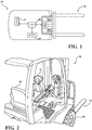
- FIG. 1 illustrates an industrial vehicle 10 in the form of a lift truck comprising conventional industrial vehicle hardware, such as a steering mechanism 15, storage and retrieval hardware 20, and a vehicle drive mechanism 25, the details of which are beyond the scope of the present disclosure and may be gleaned from conventional and yet to be developed teachings in the industrial vehicle literature - examples of which include US Pat. Nos. 6,135,694 , RE37215 , 7,017,689 , 7,681,963 , 8,131,422 , and 8,718,860 , each of which is assigned to Crown Equipment Corporation. It should be understood that although several embodiments of the industrial vehicle 10 are shown and described, any type of forklift, tractor (A.K.A.
- Trigger or automated guided vehicle is contemplated; to include those powered industrial trucks identified by the United States Department of Labor, Occupational Safety & Health Administration (OSHA) in Class I - Electric Motor Rider Trucks, Class II - Electric Motor Narrow Aisle Trucks, Class III - Electric Motor Hand Trucks or Hand/Rider Trucks, Class IV - Internal Combustion Engine Trucks (Solid/Cushion Tires), Class V - Internal Combustion Engine Trucks (Pneumatic Tires), Class VI - Electric and Internal Combustion Engine Tractors, and Class VII - Rough Terrain Forklift Trucks.
- a vehicle controller 40 controls operational functions of the industrial vehicle 10 such as the functions of the storage and retrieval hardware 20, vehicle drive mechanism 25, and/or the steering mechanism 15.
- the industrial vehicle 10 may comprise one or more user interfaces.
- the user interfaces may comprise a storage and retrieval hardware control device 23, a vehicle speed control device 24, a steering control device 14, or combinations thereof.
- the storage and retrieval hardware control device 23 may be a lever, knob, joystick, touch screen hardware control interface, or the like and configured to control the storage and retrieval hardware 20. Further discussion of the storage and retrieval hardware control device 23 is hereafter in regards to FIGS. 12-15 .
- the storage and retrieval hardware 20 may include, but is not limited to, a set of fork tines, a container handler, a turret with forks, a pantrograph, a telescopic handler, and the like.
- the vehicle speed control device 24 may be a lever, a pedal, touch screen hardware control interface, or the like and used to control the vehicle drive mechanism 25.
- the steering control device 14 may be a wheel, a knob, a lever, or the like and used to control the steering mechanism 15 which is coupled to one or more wheels 30.
- FIG. 2 illustrates one location embodiment of the storage and retrieval hardware control device 23 as coupled to an armrest 50.
- the armrest 50 is coupled to an operator chair 49. It is also contemplated, in one location embodiment, the armrest 50 is coupled to the industrial vehicle 10 for situations where the operator is required to stand or partially stand/lean to operate the industrial vehicle 10.
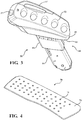
- FIG. 3 illustrates one embodiment of the armrest 50.
- the armrest 50 comprises an upper support section 55, a base section 60, and one or more ventilation and drainage apertures 53.
- the upper support section 55 may comprise at least one of a handle 57 and one or more operator input devices 27 (e.g., horn).
- the base section 60 may comprise an upper mount 63 and a lower mount 64. It is contemplated that the one or more ventilation and drainage apertures 53 atmospherically couple the atmosphere above an upper surface 51 of the armrest 50 to a lower portion of the armrest 50. Specifically, the one or more ventilation and drainage apertures 53 couple the atmosphere above the armrest 50 to the atmosphere below the upper surface 51 which is defined as the lower portion of the armrest 50.
- the lower portion of the armrest 50 is any part of the armrest 50 below the upper surface 51.
- the one or more ventilation and drainage apertures 53 serve to provide drainage of any object whether a solid, liquid, or gas, from above the upper surface 51 to lower portion of the armrest 50 and provide ventilation from the lower portion of the armrest 50 to above the upper surface 51.
- the upper surface 51 defines a plane, either flat, curved, or some combination there between which separates the armrest 50 into an area above the upper surface 51, or where an operator rests their arm, and an area below the upper surface 51.
- the ventilation and drainage apertures 53 and any associated apertures, channels, or other structure coupled to them is designed to allow, for example, water, sweat, etc., to cross the upper surface 51 from above to below and to, for example, allow air to move from below to above the upper surface 51.
- the one or more ventilation and drainage apertures 53 may take on many sizes and shapes to accomplish its function of drainage and ventilation through the upper surface 51 of the armrest 50.
- the one or more ventilation and drainage apertures 53 may be one large aperture that encompasses much of the upper surface 51, many smaller apertures sized such as pinholes, or any size or combination in between.
- an arm pad 70 may be used in conjunction with the armrest 50 shown in FIG. 3 .
- the arm pad 70 comprises a resilient material 73 and one or more pad apertures 75.
- the resilient material 73 may be, but not limited to, rubber, foam, plastic, wood, cloth and the like.
- the resilient material 73 is a hydrophobic material that is resistant to oils, detergents, chemicals, and solvents.
- the one or more pad apertures 75 may align with the one or more ventilation and drainage apertures 53 shown in FIG. 3 to allow ventilation and drainage between the upper surface 51 and below the upper surface 51. Therefore, the arm pad 70 may rest on the upper surface 51 and provide the necessary apertures to allow drainage and ventilation through the upper surface 51.
- the armrest 50 comprises the arm pad 70, the lower support section 65, and a control pod 80.
- the control pod 80, one or more position markers 66, and one or more sight windows 67 are discussed in greater detail herein below after the discussion of the ventilation and drainage features of the armrest 50.
- the arm pad 50 comprises one or more attachment mechanisms 77 in addition to the one or more pad apertures 75 and resilient material 73. It is contemplated that the one or more attachment mechanisms 77 may be push through fasteners as shown in FIG.
- reclosable fasteners such as 3MTM Dual LockTM Reclosable Fasteners, tape, adhesive, glue, cement, screws, nails, bolts and nuts, and the like fasteners used to removably couple two items together.
- the upper surface 51 is defined by the upper surface of the arm pad 70.
- the upper support section 55 may comprise one or more channels 78.
- the one or more pad apertures 75 may align with the one or more channels 78 to atmospherically couple the area above and below the upper surface 51.
- water or sweat that accumulates on the upper surface 51 may drain away from the upper surface through the one or more pad apertures 75, along the one or more channels 78, and drain from the rear portion 79 of the armrest 50.
- This embodiment illustrates only drainage of the upper surface 51. In one embodiment, it may be advantageous to ventilate the upper surface 51 as well.
- the upper support section 55 may comprise one or more vent apertures 76 to allow airflow from below the upper surface 51.
- the one or more pad apertures 75 are atmospherically coupled to the one or more vent apertures 76 such that only the one or more vent apertures 76 are present.
- both the one or more vent apertures 76 and the one or more channels 78 are present.
- the size, position, inclusion, exclusion, and arrangement of at least one of the one or more pad apertures 75, one or more channels 78, and the one or more vent apertures 76 may be changed or modified to accommodate different forms of the armrest 50.
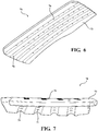
- FIGS. 6 and 7 illustrate another embodiment of the arm pad 70.
- the arm pad 70 comprises one or more vent apertures 76, resilient material 73, and one or more channels 78.
- the arm pad 70 defines the upper surface 51.
- the arm pad 70 of FIGS. 6 and 7 resides in a recess 85 in the upper support section 55 of the arm rest 50.
- FIG. 9 illustrates the arm pad 70 placed within the recess 85 of the armrest 50. It is contemplated that the arm pad 70 is removably coupled to the recess 85 as described herein before.
- the armrest 50 may comprise one or more control implements to position the armrest 50 for use by an operator.
- a first armrest control implement 88 and a second armrest control implement 89 selectably release the armrest 50 from a restrained position to allow an operator to reposition the armrest 50 for use. It is contemplated that one of the two armrest control implements selectably releases the armrest 50 from the restrained position along a fore/aft axis 83 ( FIG. 10 ) and the other control implement selectably releases the armrest 50 from the restrained position along a raised/lowered axis 84 ( FIG. 10 ).
- the fore/aft axis 83 is offset from the raised/lowered axis 84 by angle ⁇ . It is contemplated that the angle ⁇ may be modified to suit the specific industrial vehicle 10 ( FIG. 2 ) that the armrest 50 is coupled to and to account for a seated versus standing/leaning position of the operator operating the industrial vehicle 10. It should be noted that although it appears the raised/lowered axis 84 is about parallel with a maintenance axis 90, this disclosure is not limited to about parallel. The maintenance axis 90 is discussed further hereinafter in relation to FIG. 10 .
- the armrest 50 comprises a handle aperture 87 to accommodate an operator who will place their hand in the handle aperture 87 to actuate at least one of the first armrest control implement 88 and the second armrest control implement 89 and grasp the armrest 50 to reposition using only one hand.
- the armrest 50 may comprise maintenance alignment markings, exemplarily illustrated as three markings 95', 95", and 95"'. It is contemplated that the armrest 50 may have a maintenance positon along the fore/aft axis 83 and the raised/lowered axis 84 in which the armrest 50 is ideally positioned to allow the armrest 50 to be moved out of the way to allow access to a battery, engine, or other items requiring maintenance.
- the armrest 50 may be positioned in the maintenance position such that any structure the armrest 50 is coupled to can be moved, along with the armrest 50 such that the armrest 50 will avoid contact with, or receiving damage from, other parts of the industrial vehicle 50 ( FIG. 2 ).
- At least one of the first armrest control implement 88 and the second armrest control implement 89 are actuated to release the armrest 50 from the restrained position such that an operator can align the maintenance alignment markings 95', 95", 95"' along a maintenance axis 90.
- FIG. 1 in FIG.
- the armrest 50 should be moved along the fore/aft axis 83 such that marking 95'" resides along the maintenance axis 90 and moved along the raised/lowered axis 84 such that marking 95" resides over marking 95'.
- the position and alignment of the maintenance axis 90 may differ depending on the industrial vehicle 10 the armrest 50 is coupled to. It should be understood that the one or more maintenance alignment markings 95', 95", 95'" may be located anywhere on the armrest 50 and are not limited to the locations shown in the drawings.
- FIG. 11 depicts an embodiment of the armrest 50 comprising one or more position markers 66.
- a fore/aft position marker 98 and a raised lowered position marker 99 may be used by an operator to identify the current restrained position of the armrest 50 and enable repeatable positioning of the armrest 50 during subsequent uses of the industrial vehicle 10 ( FIG. 2 ) or another industrial vehicle with an armrest 50.
- the armrest 50 may comprise one or more sight windows 67 to specifically highlight the position of the armrest 50 in relation to the one or more position markers 66.
- the maintenance alignment markings may be bold or boxed 96 or the like to indicate the ideal positon of the armrest 50 to access maintenance items below the operator chair 49 ( FIG. 2 ) thereby negating the need for the maintenance alignment markings 95 shown in FIG. 10 .
- the one or more position markers 66 may be located anywhere on the armrest 50 and are not limited to the locations shown in the drawings.
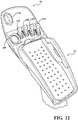
- FIGS. 12 and 13 illustrate one embodiment of the control pod 80 comprising one or more fingertip control levers 100, a direction control switch 105, and one or more status indicators 110.
- the fingertip control levers 100 and the direction control switch 105 are positioned to fit a hand 115 ( FIG. 13 ) of a typical operator. Specifically, it is contemplated that a thumb 117 of the hand 115 will rest on the direction control switch 105, and each finger 118 will rest on a fingertip control levers 100.
- each fingertip control lever 100 in relation to each other and the direction control switch 105 is not uniform and serves to mimic the unique hand 115 shape such that the hand 115 does not need to move or rotate and actuation of each fingertip control lever 100 and the direction control switch 105 is done by the fingertips and thumb tip respectively following a "finger-four" design rubric.
- the one or more status indicators provide indication of vehicle parameters.
- the one or more fingertip control levers 100, a direction control switch 105, and one or more status indicators 110 are communicatively coupled to the vehicle controller 40 ( FIG. 1 ) and serve as the storage and retrieval hardware control device 23 ( FIG. 2 ).
- FIG. 14 illustrates another embodiment of the control pod 80 comprising one or more joysticks 120 and a direction control switch 105.
- the one or more joysticks 120 and the direction controls switch 105 are communicatively coupled to the vehicle controller 40 ( FIG. 1 ) and serve as the storage and retrieval hardware control device 23 ( FIG. 2 ).
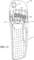
- FIG. 15 illustrates another embodiment of the control pod 80 comprising one or more mini-levers 125 and direction control device 105.
- the one or more mini-levers 125 and direction control device 105 are shown and described in co-pending US Provisional Application No. 62/291,968 filed February 5, 2016 and US Non-Provisional Application with attorney docket number CRN 859 PA and claiming priority to the above noted provisional application, both of which are herein incorporated by reference in their entirety.
Landscapes
- Engineering & Computer Science (AREA)
- Mechanical Engineering (AREA)
- Aviation & Aerospace Engineering (AREA)
- Transportation (AREA)
- Physics & Mathematics (AREA)
- General Physics & Mathematics (AREA)
- Automation & Control Theory (AREA)
- Power Engineering (AREA)
- Thermal Sciences (AREA)
- Forklifts And Lifting Vehicles (AREA)
- Seats For Vehicles (AREA)
Abstract
Description
- The present invention relates to an armrest for an industrial vehicle, and an industrial vehicle having an armrest.
- In accordance with a first aspect of the present invention, an armrest comprises an upper support section having one or more ventilation and drainage apertures that couple an upper surface of the upper support section to a lower portion of the armrest to facilitate airflow and drainage between the upper surface of the upper support section and the lower portion of the armrest. The armrest further comprises one or more control implements and an arm pad removably coupled to the upper support section, the arm pad comprising one or more pad apertures formed therein that communicate with the ventilation and drainage apertures to allow ventilation and drainage between an upper surface of the arm pad and the lower portion of the armrest.
- The upper support section may further comprise one or more drainage channels, the one or more drainage channels being substantially parallel to each other and aligned with the one or more pad apertures to atmospherically couple areas above and below the upper surface of the arm pad, and one or more vent apertures that are atmospherically coupled to one or more of the one or more pad apertures.
- The arm pad may further comprise one or more vent apertures extending between the upper surface and a lower surface of the arm pad, and one or more drainage channels, each drainage channel positioned about parallel to each other on the lower surface of the arm pad.
- Each drainage channel may be substantially parallel with an armrest axis, and each vent aperture may be substantially orthogonal to an armrest axis.
- The armrest may further comprise a handle coupled to the upper support section, wherein the one or more control implements comprise armrest control implements coupled to the upper support section that selectably release or restrain the armrest between ergonomic positions.
- In accordance with a second aspect of the present invention, an armrest comprises an upper support section, one or more control implements, and an arm pad removably coupled to the upper support section, the arm pad comprising an upper surface with one or more pad apertures formed therein that atmospherically couple areas above and below the upper surface of the arm pad. At least one of the upper support section or the arm pad comprises one or more drainage channels, the one or more drainage channels being substantially parallel to each other and aligned with the one or more pad apertures to atmospherically couple areas above and below the upper surface of the arm pad.
- Each drainage channel may be substantially parallel with an armrest axis, and each pad aperture may be substantially orthogonal to the armrest axis.
- The upper support section may further comprise one or more vent apertures that are atmospherically coupled to one or more of the one or more pad apertures.
- The armrest may further comprise a handle coupled to the upper support section, wherein the one or more control implements comprise armrest control implements coupled to the upper support section that selectably release or restrain the armrest between ergonomic positions.
- In accordance with a third aspect of the present invention, an industrial vehicle comprises an operator chair including an armrest, the armrest comprising an upper support section having one or more ventilation and drainage apertures that couple an upper surface of the upper support section to a lower portion of the armrest to facilitate airflow and drainage between the upper surface of the upper support section and the lower portion of the armrest. The armrest further comprises one or more control implements and an arm pad removably coupled to the upper support section, the arm pad comprising one or more pad apertures formed therein that communicate with the ventilation and drainage apertures to allow ventilation and drainage between an upper surface of the arm pad and the lower portion of the armrest.
- The one or more control implements may comprise vehicle control implements in the form of one or more joysticks arranged on or about an orthogonal axis to an armrest axis.
- The one or more control implements may comprise vehicle control implements in the form of a plurality of mini-levers arranged on or about a shallow arc centered off the armrest.
- The one or more control implements may comprise vehicle control implements in the form of a plurality of fingertip control levers having at least two degrees of freedom to actuate a vehicle function.
- The upper support section may further comprise one or more drainage channels, the one or more drainage channels being substantially parallel to each other and aligned with the one or more pad apertures to atmospherically couple areas above and below the upper surface of the arm pad.
- The arm pad may further comprise one or more vent apertures extending between upper and lower surfaces of the arm pad, and one or more drainage channels, each drainage channel positioned about parallel to each other on the lower surface of the arm pad.
- Each drainage channel may be substantially parallel with an armrest axis, and each vent aperture may be substantially orthogonal to the armrest axis.
- The armrest may further comprise a handle coupled to the upper support section, wherein the one or more control implements comprise armrest control implements coupled to the upper support section that selectably release or restrain the armrest between ergonomic positions.
- The embodiments set forth in the drawings are illustrative and not intended to limit the subject matter defined by the claims. The following detailed description of the illustrative embodiments can be understood when read in conjunction with the following drawings, where like structure is indicated with like reference numerals and in which:
-
FIG. 1 depicts a top view of an industrial vehicle according to one or more embodiments shown and described herein; -
FIG. 2 depicts a perspective view of the industrial vehicle according to one or more embodiments shown and described herein; -
FIG. 3 depicts a perspective view of an armrest according to one or more embodiments shown and described herein; -
FIG. 4 depicts a perspective view of an arm pad according to one or more embodiments shown and described herein; -
FIG. 5 depicts a perspective view of the armrest according to one or more embodiments shown and described herein; -
FIG. 6 depicts a perspective view of the arm pad according to one or more embodiments shown and described herein; -
FIG. 7 depicts a front view of the arm pad according to one or more embodiments shown and described herein; -
FIG. 8 depicts a perspective view of the armrest according to one or more embodiments shown and described herein; -
FIG. 9 depicts a perspective view of the armrest according to one or more embodiments shown and described herein; -
FIG. 10 depicts a left side view of the armrest according to one or more embodiments shown and described herein; -
FIG. 11 depicts a right side view of the armrest according to one or more embodiments shown and described herein; -
FIG. 12 depicts a perspective view of a control pod according to one or more embodiments shown and described herein; -
FIG. 13 depicts a top view of the control pod according to one or more embodiments shown and described herein; -
FIG. 14 depicts a perspective view of the control pod according to one or more embodiments shown and described herein; and -
FIG. 15 depicts a perspective view of the control pod according to one or more embodiments shown and described herein. - Industrial vehicle armrests may become saturated with an unclean mixture of dirt, grease, rain water, sweat, and body oil that is hard to clean and renders operator contact with the armrest unpleasant. By allowing ventilation and drainage of the upper surface of the armrest, the overall cleanliness of the armrest is improved by reducing the accumulation of the unclean mixture thereby increasing operator comfort and productivity. Further, it is contemplated that a removable arm pad will further the goals of operator comfort and productivity by allowing the upper surface of the armrest to be replaced when the unclean mixture becomes difficult or impossible to remove. The addition of armrest position markers and maintenance alignment markings further increase productivity of the operator by increasing the speed at which an armrest is positioned for operator use and comfort in regards to the position markers and quickly positioning the armrest for service of the industrial vehicle in regards to the maintenance markers.
-
FIG. 1 illustrates anindustrial vehicle 10 in the form of a lift truck comprising conventional industrial vehicle hardware, such as asteering mechanism 15, storage andretrieval hardware 20, and avehicle drive mechanism 25, the details of which are beyond the scope of the present disclosure and may be gleaned from conventional and yet to be developed teachings in the industrial vehicle literature - examples of which includeUS Pat. Nos. 6,135,694 ,RE37215 ,7,017,689 ,7,681,963 ,8,131,422 , and8,718,860 , each of which is assigned to Crown Equipment Corporation. It should be understood that although several embodiments of theindustrial vehicle 10 are shown and described, any type of forklift, tractor (A.K.A. "tugger"), or automated guided vehicle is contemplated; to include those powered industrial trucks identified by the United States Department of Labor, Occupational Safety & Health Administration (OSHA) in Class I - Electric Motor Rider Trucks, Class II - Electric Motor Narrow Aisle Trucks, Class III - Electric Motor Hand Trucks or Hand/Rider Trucks, Class IV - Internal Combustion Engine Trucks (Solid/Cushion Tires), Class V - Internal Combustion Engine Trucks (Pneumatic Tires), Class VI - Electric and Internal Combustion Engine Tractors, and Class VII - Rough Terrain Forklift Trucks. Avehicle controller 40 controls operational functions of theindustrial vehicle 10 such as the functions of the storage and retrievalhardware 20,vehicle drive mechanism 25, and/or thesteering mechanism 15. - Referring to
FIG. 2 , theindustrial vehicle 10 may comprise one or more user interfaces. For example, and not by way of limitation, the user interfaces may comprise a storage and retrievalhardware control device 23, a vehiclespeed control device 24, asteering control device 14, or combinations thereof. It should be understood by those skilled in the art that the storage and retrievalhardware control device 23 may be a lever, knob, joystick, touch screen hardware control interface, or the like and configured to control the storage and retrievalhardware 20. Further discussion of the storage and retrievalhardware control device 23 is hereafter in regards toFIGS. 12-15 . The storage andretrieval hardware 20 may include, but is not limited to, a set of fork tines, a container handler, a turret with forks, a pantrograph, a telescopic handler, and the like. The vehiclespeed control device 24 may be a lever, a pedal, touch screen hardware control interface, or the like and used to control thevehicle drive mechanism 25. Thesteering control device 14 may be a wheel, a knob, a lever, or the like and used to control thesteering mechanism 15 which is coupled to one ormore wheels 30. -
FIG. 2 illustrates one location embodiment of the storage and retrievalhardware control device 23 as coupled to anarmrest 50. In one location embodiment, thearmrest 50 is coupled to anoperator chair 49. It is also contemplated, in one location embodiment, thearmrest 50 is coupled to theindustrial vehicle 10 for situations where the operator is required to stand or partially stand/lean to operate theindustrial vehicle 10. -
FIG. 3 illustrates one embodiment of thearmrest 50. Thearmrest 50 comprises anupper support section 55, a base section 60, and one or more ventilation anddrainage apertures 53. Theupper support section 55 may comprise at least one of ahandle 57 and one or more operator input devices 27 (e.g., horn). The base section 60 may comprise anupper mount 63 and alower mount 64. It is contemplated that the one or more ventilation anddrainage apertures 53 atmospherically couple the atmosphere above anupper surface 51 of the armrest 50 to a lower portion of thearmrest 50. Specifically, the one or more ventilation anddrainage apertures 53 couple the atmosphere above the armrest 50 to the atmosphere below theupper surface 51 which is defined as the lower portion of thearmrest 50. In other words, the lower portion of thearmrest 50 is any part of thearmrest 50 below theupper surface 51. The one or more ventilation anddrainage apertures 53 serve to provide drainage of any object whether a solid, liquid, or gas, from above theupper surface 51 to lower portion of thearmrest 50 and provide ventilation from the lower portion of the armrest 50 to above theupper surface 51. In other words, it is contemplated that theupper surface 51 defines a plane, either flat, curved, or some combination there between which separates the armrest 50 into an area above theupper surface 51, or where an operator rests their arm, and an area below theupper surface 51. It is an atmospheric coupling of these two areas in which the ventilation anddrainage apertures 53 and any associated apertures, channels, or other structure coupled to them is designed to allow, for example, water, sweat, etc., to cross theupper surface 51 from above to below and to, for example, allow air to move from below to above theupper surface 51. As explained in greater detail hereinafter, the one or more ventilation anddrainage apertures 53 may take on many sizes and shapes to accomplish its function of drainage and ventilation through theupper surface 51 of thearmrest 50. For example, and not by way of limitation, it is contemplated that the one or more ventilation anddrainage apertures 53 may be one large aperture that encompasses much of theupper surface 51, many smaller apertures sized such as pinholes, or any size or combination in between. - Referring now to
FIG. 4 , anarm pad 70 may be used in conjunction with the armrest 50 shown inFIG. 3 . Thearm pad 70 comprises aresilient material 73 and one ormore pad apertures 75. Theresilient material 73 may be, but not limited to, rubber, foam, plastic, wood, cloth and the like. In one embodiment, theresilient material 73 is a hydrophobic material that is resistant to oils, detergents, chemicals, and solvents. In one embodiment, the one ormore pad apertures 75 may align with the one or more ventilation anddrainage apertures 53 shown inFIG. 3 to allow ventilation and drainage between theupper surface 51 and below theupper surface 51. Therefore, thearm pad 70 may rest on theupper surface 51 and provide the necessary apertures to allow drainage and ventilation through theupper surface 51. - Referring now to
FIG. 5 , one embodiment of thearmrest 50 is shown. In this embodiment, thearmrest 50 comprises thearm pad 70, thelower support section 65, and acontrol pod 80. Thecontrol pod 80, one ormore position markers 66, and one ormore sight windows 67 are discussed in greater detail herein below after the discussion of the ventilation and drainage features of thearmrest 50. Still referring toFIG. 5 , thearm pad 50 comprises one ormore attachment mechanisms 77 in addition to the one ormore pad apertures 75 andresilient material 73. It is contemplated that the one ormore attachment mechanisms 77 may be push through fasteners as shown inFIG. 5 or they may be snap buttons, hook and loop fasteners, reclosable fasteners such as 3M™ Dual Lock™ Reclosable Fasteners, tape, adhesive, glue, cement, screws, nails, bolts and nuts, and the like fasteners used to removably couple two items together. - In the embodiment shown in
FIG. 5 , theupper surface 51 is defined by the upper surface of thearm pad 70. Theupper support section 55 may comprise one ormore channels 78. The one ormore pad apertures 75 may align with the one ormore channels 78 to atmospherically couple the area above and below theupper surface 51. For example, and not by way of limitation, water or sweat that accumulates on theupper surface 51 may drain away from the upper surface through the one ormore pad apertures 75, along the one ormore channels 78, and drain from therear portion 79 of thearmrest 50. This embodiment illustrates only drainage of theupper surface 51. In one embodiment, it may be advantageous to ventilate theupper surface 51 as well. Theupper support section 55 may comprise one ormore vent apertures 76 to allow airflow from below theupper surface 51. In this embodiment, the one ormore pad apertures 75 are atmospherically coupled to the one ormore vent apertures 76 such that only the one ormore vent apertures 76 are present. In yet another embodiment, both the one ormore vent apertures 76 and the one ormore channels 78 are present. In other words, it is contemplated that the size, position, inclusion, exclusion, and arrangement of at least one of the one ormore pad apertures 75, one ormore channels 78, and the one ormore vent apertures 76 may be changed or modified to accommodate different forms of thearmrest 50. -
FIGS. 6 and 7 illustrate another embodiment of thearm pad 70. In this embodiment, thearm pad 70 comprises one ormore vent apertures 76,resilient material 73, and one ormore channels 78. In this embodiment, thearm pad 70 defines theupper surface 51. Referring toFIG. 8 , thearm pad 70 ofFIGS. 6 and 7 resides in arecess 85 in theupper support section 55 of thearm rest 50.FIG. 9 illustrates thearm pad 70 placed within therecess 85 of thearmrest 50. It is contemplated that thearm pad 70 is removably coupled to therecess 85 as described herein before. - In one embodiment, the
armrest 50 may comprise one or more control implements to position thearmrest 50 for use by an operator. Referring now toFIGS. 8 and9 , a first armrest control implement 88 and a second armrest control implement 89 selectably release the armrest 50 from a restrained position to allow an operator to reposition thearmrest 50 for use. It is contemplated that one of the two armrest control implements selectably releases the armrest 50 from the restrained position along a fore/aft axis 83 (FIG. 10 ) and the other control implement selectably releases the armrest 50 from the restrained position along a raised/lowered axis 84 (FIG. 10 ). The fore/aft axis 83 is offset from the raised/loweredaxis 84 by angle Ø. It is contemplated that the angle Ø may be modified to suit the specific industrial vehicle 10 (FIG. 2 ) that thearmrest 50 is coupled to and to account for a seated versus standing/leaning position of the operator operating theindustrial vehicle 10. It should be noted that although it appears the raised/loweredaxis 84 is about parallel with a maintenance axis 90, this disclosure is not limited to about parallel. The maintenance axis 90 is discussed further hereinafter in relation toFIG. 10 . - Still referring to
FIGS. 8 and9 , thearmrest 50 comprises ahandle aperture 87 to accommodate an operator who will place their hand in thehandle aperture 87 to actuate at least one of the first armrest control implement 88 and the second armrest control implement 89 and grasp the armrest 50 to reposition using only one hand. - Referring now to
FIG. 10 , in one embodiment, thearmrest 50 may comprise maintenance alignment markings, exemplarily illustrated as threemarkings 95', 95", and 95"'. It is contemplated that the armrest 50 may have a maintenance positon along the fore/aft axis 83 and the raised/loweredaxis 84 in which thearmrest 50 is ideally positioned to allow the armrest 50 to be moved out of the way to allow access to a battery, engine, or other items requiring maintenance. For example, and not by way of limitation, thearmrest 50 may be positioned in the maintenance position such that any structure thearmrest 50 is coupled to can be moved, along with the armrest 50 such that the armrest 50 will avoid contact with, or receiving damage from, other parts of the industrial vehicle 50 (FIG. 2 ). At least one of the first armrest control implement 88 and the second armrest control implement 89 are actuated to release the armrest 50 from the restrained position such that an operator can align themaintenance alignment markings 95', 95", 95"' along a maintenance axis 90. For example, and not by way of limitation, inFIG. 10 , the armrest 50 should be moved along the fore/aft axis 83 such that marking 95'" resides along the maintenance axis 90 and moved along the raised/loweredaxis 84 such that marking 95" resides over marking 95'. The position and alignment of the maintenance axis 90 may differ depending on theindustrial vehicle 10 thearmrest 50 is coupled to. It should be understood that the one or moremaintenance alignment markings 95', 95", 95'" may be located anywhere on thearmrest 50 and are not limited to the locations shown in the drawings. -
FIG. 11 depicts an embodiment of the armrest 50 comprising one ormore position markers 66. A fore/aft position marker 98 and a raised lowered position marker 99 may be used by an operator to identify the current restrained position of thearmrest 50 and enable repeatable positioning of the armrest 50 during subsequent uses of the industrial vehicle 10 (FIG. 2 ) or another industrial vehicle with anarmrest 50. Referring toFIG. 5 , in one embodiment, thearmrest 50 may comprise one ormore sight windows 67 to specifically highlight the position of the armrest 50 in relation to the one ormore position markers 66. It is further contemplated that the maintenance alignment markings may be bold or boxed 96 or the like to indicate the ideal positon of the armrest 50 to access maintenance items below the operator chair 49 (FIG. 2 ) thereby negating the need for themaintenance alignment markings 95 shown inFIG. 10 . It should be understood that the one ormore position markers 66 may be located anywhere on thearmrest 50 and are not limited to the locations shown in the drawings. -
FIGS. 12 and13 illustrate one embodiment of thecontrol pod 80 comprising one or more fingertip control levers 100, adirection control switch 105, and one ormore status indicators 110. The fingertip control levers 100 and thedirection control switch 105 are positioned to fit a hand 115 (FIG. 13 ) of a typical operator. Specifically, it is contemplated that athumb 117 of thehand 115 will rest on thedirection control switch 105, and eachfinger 118 will rest on a fingertip control levers 100. Therefore, the spacing and orientation of eachfingertip control lever 100 in relation to each other and thedirection control switch 105 is not uniform and serves to mimic theunique hand 115 shape such that thehand 115 does not need to move or rotate and actuation of eachfingertip control lever 100 and thedirection control switch 105 is done by the fingertips and thumb tip respectively following a "finger-four" design rubric. The one or more status indicators provide indication of vehicle parameters. The one or more fingertip control levers 100, adirection control switch 105, and one ormore status indicators 110 are communicatively coupled to the vehicle controller 40 (FIG. 1 ) and serve as the storage and retrieval hardware control device 23 (FIG. 2 ). -
FIG. 14 illustrates another embodiment of thecontrol pod 80 comprising one ormore joysticks 120 and adirection control switch 105. The one ormore joysticks 120 and the direction controls switch 105 are communicatively coupled to the vehicle controller 40 (FIG. 1 ) and serve as the storage and retrieval hardware control device 23 (FIG. 2 ). -
FIG. 15 illustrates another embodiment of thecontrol pod 80 comprising one or more mini-levers 125 anddirection control device 105. The one or more mini-levers 125 and direction control device 105 (bothFIGS. 14 and15 ) are shown and described in co-pendingUS Provisional Application No. 62/291,968 filed February 5, 2016 - The text of this disclosure sets forth a broad description of numerous different embodiments. The description is to be construed as exemplary only and does not describe every possible embodiment since describing every possible embodiment would be impractical, if not impossible, and it will be understood that any feature, characteristic, component, composition, ingredient, product, step, or methodology described herein can be deleted, combined with or substituted for, in whole or part, any other feature, characteristic, component, composition, ingredient, product, step or methodology described herein. It should be understood that multiple combinations of the embodiments described and shown are contemplated and that a particular focus on one embodiment does not preclude its inclusion in a combination of other described embodiments. Numerous alternative embodiments could also be implemented, using either current technology or technology developed after the filing date of this patent, which would still fall within the scope of the claims. All publications and patents cited herein are incorporated herein by reference in their entirety.
- Unless otherwise defined, all technical and scientific terms used herein have the same meaning as commonly understood by one of ordinary skill in the art to which the claimed subject matter belongs. The terminology used in the description herein is for describing particular embodiments only and is not intended to be limiting. As used in the specification and appended claims, the singular forms "a," "an," and "the" are intended to include the plural forms as well, unless the context clearly indicates otherwise.
- It is noted that the terms "substantially" and "about" may be utilized herein to represent the inherent degree of uncertainty that may be attributed to any quantitative comparison, value, measurement, or other representation. These terms are also utilized herein to represent the degree by which a quantitative representation may vary from a stated reference without resulting in a change in the basic function of the subject matter at issue.
- Certain terminology is used in the disclosure for convenience only and is not limiting. The words "left", "right", "front", "back", "upper", and "lower" designate directions in the drawings to which reference is made. The terminology includes the words noted above as well as derivatives thereof and words of similar import.
- While particular embodiments have been illustrated and described herein, it should be understood that various other changes and modifications may be made without departing from the spirit and scope of the claimed subject matter. Moreover, although various aspects of the claimed subject matter have been described herein, such aspects need not be utilized in combination. It is therefore intended that the appended claims cover all such changes and modifications that are within the scope of the claimed subject matter.
- Alternative expressions of the inventive concept are set out in the following numbered clauses:
- 1. An armrest comprising:
- an upper support section having one or more ventilation and drainage apertures that couple an upper surface of the upper support section to a lower portion of the armrest to facilitate airflow and drainage between the upper surface of the upper support section and the lower portion of the armrest;
- one or more control implements; and
- an arm pad removably coupled to the upper support section, the arm pad comprising one or more pad apertures formed therein that communicate with the ventilation and drainage apertures to allow ventilation and drainage between an upper surface of the arm pad and the lower portion of the armrest.
- 2. The armrest of clause 1, wherein the upper support section further comprises one or more drainage channels, the one or more drainage channels being substantially parallel to each other and aligned with the one or more pad apertures to atmospherically couple areas above and below the upper surface of the arm pad.
- 3. The armrest of clause 2, wherein the upper support section further comprises one or more vent apertures that are atmospherically coupled to one or more of the one or more pad apertures.
- 4. The armrest of clause 1, wherein the arm pad further comprises:
- one or more vent apertures extending between the upper surface and a lower surface of the arm pad; and
- one or more drainage channels, each drainage channel positioned about parallel to each other on the lower surface of the arm pad.
- 5. The armrest of clause 4, wherein each drainage channel is substantially parallel with an armrest axis.
- 6. The armrest of clause 4, wherein each vent aperture is substantially orthogonal to an armrest axis.
- 7. The armrest of clause 1, further comprising a handle coupled to the upper support section, wherein the one or more control implements comprise armrest control implements coupled to the upper support section that selectably release or restrain the armrest between ergonomic positions.
- 8. An armrest comprising:
- an upper support section;
- one or more control implements; and
- an arm pad removably coupled to the upper support section, the arm pad comprising an upper surface with one or more pad apertures formed therein that atmospherically couple areas above and below the upper surface of the arm pad;
- wherein at least one of the upper support section or the arm pad comprises one or more drainage channels, the one or more drainage channels being substantially parallel to each other and aligned with the one or more pad apertures to atmospherically couple areas above and below the upper surface of the arm pad.
- 9. The armrest of clause 8, wherein each drainage channel is substantially parallel with an armrest axis.
- 10. The armrest of clause 9, wherein each pad aperture is substantially orthogonal to the armrest axis.
- 11. The armrest of clause 8, wherein the upper support section further comprises one or more vent apertures that are atmospherically coupled to one or more of the one or more pad apertures.
- 12. The armrest of clause 8, further comprising a handle coupled to the upper support section, wherein the one or more control implements comprise armrest control implements coupled to the upper support section that selectably release or restrain the armrest between ergonomic positions.
- 13. An industrial vehicle comprising:
an operator chair including an armrest, the armrest comprising:- an upper support section having one or more ventilation and drainage apertures that couple an upper surface of the upper support section to a lower portion of the armrest to facilitate airflow and drainage between the upper surface of the upper support section and the lower portion of the armrest;
- one or more control implements; and
- an arm pad removably coupled to the upper support section, the arm pad comprising one or more pad apertures formed therein that communicate with the ventilation and drainage apertures to allow ventilation and drainage between an upper surface of the arm pad and the lower portion of the armrest.
- 14. The industrial truck of clause 13, wherein the one or more control implements comprise vehicle control implements in the form of one or more joysticks arranged on or about an orthogonal axis to an armrest axis.
- 15. The industrial truck of clause 13, wherein the one or more control implements comprise vehicle control implements in the form of a plurality of mini-levers arranged on or about a shallow arc centered off the armrest.
- 16. The industrial truck of clause 13, wherein the one or more control implements comprise vehicle control implements in the form of a plurality of fingertip control levers having at least two degrees of freedom to actuate a vehicle function.
- 17. The industrial truck of clause 13, wherein the upper support section further comprises one or more drainage channels, the one or more drainage channels being substantially parallel to each other and aligned with the one or more pad apertures to atmospherically couple areas above and below the upper surface of the arm pad.
- 18. The industrial truck of clause 13, wherein the arm pad further comprises:
- one or more vent apertures extending between upper and lower surfaces of the arm pad; and
- one or more drainage channels, each drainage channel positioned about parallel to each other on the lower surface of the arm pad.
- 19. The industrial truck of clause 18, wherein each drainage channel is substantially parallel with an armrest axis.
- 20. The industrial truck of clause 19, wherein each vent aperture is substantially orthogonal to the armrest axis.
- 21. The industrial truck of clause 13, wherein the armrest further comprises a handle coupled to the upper support section, wherein the one or more control implements comprise armrest control implements coupled to the upper support section that selectably release or restrain the armrest between ergonomic positions.
Claims (15)
- An armrest comprising:an upper support section;a base section; andone or more markers or markings used by an operator to identify the current position of the armrest, wherein the one or more markers or markings are located on one or both of the upper support section and the base section.
- The armrest of claim 1, wherein the one or more markers or markings include at least one marking along a fore/aft axis of the armrest.
- The armrest of claim 1 or claim 2, wherein the one or more markers or markings include at least one marking along a raised/lowered axis of the armrest.
- The armrest of any preceding claim, wherein the armrest defines a maintenance axis which aligns with the one or more markers or markings when the armrest resides in an ideal maintenance position, wherein when the armrest is in the ideal maintenance position, the armrest is positioned to allow the armrest to be moved out of the way to allow access to a battery or engine during maintenance of a vehicle in which the armrest is used.
- The armrest of claim 4, wherein the one or more markers or markings include at least one marking along a fore/aft axis of the armrest, and wherein the armrest is in the ideal maintenance position when the at least one marking along the fore/aft axis resides along the maintenance axis.
- The armrest of claim 4 or claim 5, wherein the one or more markers or markings include a first marking and a second marking along a raised/lowered axis of the armrest, and wherein the armrest is in the ideal maintenance position when the second marking resides over the first marking.
- The armrest of claim 4, wherein:the one or more markers or markings include at least one marking along a fore/aft axis of the armrest;the one or more markers or markings include a first marking and a second marking along a raised/lowered axis of the armrest; andwherein the armrest is in the ideal maintenance position when the at least one marking along the fore/aft axis resides along the maintenance axis and when the second marking along the raised/lowered axis resides over the first marking along the raised/lowered axis.
- The armrest of any preceding claim, wherein the one or more markers or markings include a plurality of markers along a fore/aft axis of the armrest.
- The armrest of any preceding claim, wherein the one or more markers or markings include a plurality of markers along a raised/lowered axis of the armrest.
- The armrest of any preceding claim, wherein the armrest comprises one or more sight windows to highlight the position of the armrest in relation to one or more markers.
- The armrest of any preceding claim, wherein at least one marker or marking is boxed to indicate the ideal maintenance position for the armrest; or wherein the at least one maintenance alignment marking is bolded to indicate the ideal maintenance position for the armrest.
- The armrest of any preceding claim, wherein the armrest further comprises one or more ventilation and drainage apertures.
- The armrest of Claim 12, wherein the armrest further comprises an upper surface wherein the one or more ventilation and drainage apertures atmospherically couple the atmosphere above the upper surface to the atmosphere below the upper surface.
- The armrest of any preceding claim, wherein the one or more markers or markings comprises a first maintenance alignment marking along a fore/aft axis of the armrest that corresponds to an ideal maintenance position for the armrest along the fore/aft axis, and a second maintenance alignment marking along a raised/lowered axis of the armrest that corresponds to an ideal maintenance position for the armrest along the raised/lowered axis; and
wherein when the armrest is in the ideal maintenance position, the armrest is able to be moved out of the way to allow access to maintenance items below an operator's chair positioned adjacent to the armrest. - The armrest of claim 14, wherein the first and second maintenance alignment markings are boxed to indicate the ideal maintenance position for the armrest; or wherein the first and second maintenance alignment markings are bolded to indicate the ideal maintenance position for the armrest.
Applications Claiming Priority (3)
| Application Number | Priority Date | Filing Date | Title |
|---|---|---|---|
| US201762445789P | 2017-01-13 | 2017-01-13 | |
| EP18702038.3A EP3568318B1 (en) | 2017-01-13 | 2018-01-12 | Industrial vehicle armrest |
| PCT/US2018/013485 WO2018132654A1 (en) | 2017-01-13 | 2018-01-12 | Industrial vehicle armrest |
Related Parent Applications (1)
| Application Number | Title | Priority Date | Filing Date |
|---|---|---|---|
| EP18702038.3A Division EP3568318B1 (en) | 2017-01-13 | 2018-01-12 | Industrial vehicle armrest |
Publications (1)
| Publication Number | Publication Date |
|---|---|
| EP3858664A1 true EP3858664A1 (en) | 2021-08-04 |
Family
ID=61074619
Family Applications (2)
| Application Number | Title | Priority Date | Filing Date |
|---|---|---|---|
| EP18702038.3A Active EP3568318B1 (en) | 2017-01-13 | 2018-01-12 | Industrial vehicle armrest |
| EP21158301.8A Pending EP3858664A1 (en) | 2017-01-13 | 2018-01-12 | Industrial vehicle armrest |
Family Applications Before (1)
| Application Number | Title | Priority Date | Filing Date |
|---|---|---|---|
| EP18702038.3A Active EP3568318B1 (en) | 2017-01-13 | 2018-01-12 | Industrial vehicle armrest |
Country Status (8)
| Country | Link |
|---|---|
| US (1) | US10358063B2 (en) |
| EP (2) | EP3568318B1 (en) |
| KR (1) | KR102404298B1 (en) |
| CN (1) | CN110062717B (en) |
| AU (1) | AU2018207133B2 (en) |
| CA (1) | CA3047345C (en) |
| MX (1) | MX395236B (en) |
| WO (1) | WO2018132654A1 (en) |
Families Citing this family (10)
| Publication number | Priority date | Publication date | Assignee | Title |
|---|---|---|---|---|
| JP6437992B2 (en) * | 2016-12-20 | 2018-12-12 | トヨタ自動車九州株式会社 | Vehicle control unit structure |
| JP6686930B2 (en) * | 2017-02-21 | 2020-04-22 | トヨタ自動車株式会社 | Driving support device |
| WO2019080957A1 (en) * | 2017-10-27 | 2019-05-02 | Gentherm Gmbh | SURFACE tempering |
| KR102552518B1 (en) * | 2018-12-11 | 2023-07-05 | 두산산업차량 주식회사 | Armrest apparatus |
| US10941540B2 (en) | 2019-01-30 | 2021-03-09 | Caterpillar Inc. | Adjustable operator console for machine control |
| JP7211204B2 (en) * | 2019-03-27 | 2023-01-24 | 豊田合成株式会社 | Proximity air conditioning unit for vehicle |
| JP7275007B2 (en) * | 2019-11-08 | 2023-05-17 | 株式会社クボタ | work vehicle |
| US11299079B1 (en) * | 2021-03-10 | 2022-04-12 | Ford Global Technologies, Llc | Armrest with cushioned component having an integrated air channeling system |
| US20250222841A1 (en) * | 2021-10-28 | 2025-07-10 | Charles J Cauchy | Weather resistant air flow distribution system for seats |
| EP4173889A1 (en) * | 2021-10-29 | 2023-05-03 | AMI Industries, Inc. | Air conditioning system for a seat |
Citations (8)
| Publication number | Priority date | Publication date | Assignee | Title |
|---|---|---|---|---|
| DE8420100U1 (en) * | 1984-07-05 | 1984-09-27 | Drabert Söhne Minden (Westf.), 4950 Minden | SEAT FURNITURE WITH ARMREST |
| US6135694A (en) | 1997-09-30 | 2000-10-24 | Crown Equipment Corporation | Travel and fork lowering speed control based on fork load weight/tilt cylinder operation |
| USRE37215E1 (en) | 1995-05-12 | 2001-06-12 | Crown Equipment Corporation | Fork level indicator for lift trucks |
| US7017689B2 (en) | 2004-05-06 | 2006-03-28 | Crown Equipment Corporation | Electrical steering assist for material handling vehicles |
| US7681963B2 (en) | 2005-03-07 | 2010-03-23 | Crown Equipment Corporation | Braking system for a lift truck |
| US8131422B2 (en) | 2008-05-05 | 2012-03-06 | Crown Equipment Corporation | Slip control for a materials handling vehicle |
| US8718860B2 (en) | 2011-08-29 | 2014-05-06 | Crown Equipment Corporation | Vehicle control limits |
| KR200479799Y1 (en) * | 2015-10-23 | 2016-03-08 | 엄기현 | seat arm rest for excavator |
Family Cites Families (63)
| Publication number | Priority date | Publication date | Assignee | Title |
|---|---|---|---|---|
| FR1527047A (en) | 1967-04-13 | 1968-05-31 | Renault | Seats for heavy vehicles |
| DE3722814A1 (en) | 1987-07-10 | 1989-01-19 | Grammer Sitzsysteme Gmbh | Foam-backed article and process for the production thereof |
| JPH0357415A (en) | 1989-07-26 | 1991-03-12 | Matsushita Electric Ind Co Ltd | Air conditioner |
| JP3257109B2 (en) | 1993-01-19 | 2002-02-18 | 株式会社デンソー | Vehicle refrigeration cycle control device |
| JPH08286782A (en) | 1995-04-11 | 1996-11-01 | Masatoshi Sakagami | Arm rest |
| JP2000185674A (en) | 1998-12-22 | 2000-07-04 | Honda Motor Co Ltd | Freight vehicle |
| US6347771B1 (en) | 1999-06-11 | 2002-02-19 | Pierre Lauzon | Portable arm and mouse support for use with personal computers |
| JP3305685B2 (en) | 1999-07-30 | 2002-07-24 | 株式会社タチエス | Armrest manufacturing method |
| JP3460190B2 (en) | 1999-08-31 | 2003-10-27 | 株式会社タチエス | Armrest structure |
| AU783829B2 (en) | 2000-09-28 | 2005-12-08 | Formway Furniture Limited | A reclinable chair |
| JP2003292298A (en) | 2002-04-03 | 2003-10-15 | Toyota Industries Corp | Industrial vehicle |
| DE10225292A1 (en) | 2002-06-07 | 2003-12-18 | Pre Prototyping | Motor vehicle door has electrical heater or heating tube for adjusting temperature of protruding component of internal paneling that constitutes armrest |
| DE20214711U1 (en) | 2002-09-23 | 2004-02-19 | Seeber Ag & Co. Kg | Lid supported on a support |
| JP2004130998A (en) | 2002-10-11 | 2004-04-30 | Denso Corp | Air conditioner for vehicles |
| JP2004203336A (en) | 2002-12-26 | 2004-07-22 | Denso Corp | Vehicle air conditioner |
| JP2004352160A (en) | 2003-05-30 | 2004-12-16 | Denso Corp | Vehicle air purifier |
| US6871721B2 (en) | 2003-06-03 | 2005-03-29 | The Raymond Corporation | Ergonomic operator compartment for operators of differing heights |
| DE10349410A1 (en) | 2003-10-21 | 2004-05-13 | W.E.T. Automotive Systems Ag | Air conditioning device for vehicle interior components has ventilation device in support feeding cooled air into or heated air out of interior, coating transmissive to air, distancing arrangement |
| JP2005255000A (en) * | 2004-03-11 | 2005-09-22 | Denso Corp | Air conditioner for vehicles |
| DE102004019397B4 (en) | 2004-04-19 | 2012-01-26 | Ab Skf | Armrest and seat with the armrest |
| JP2006076503A (en) | 2004-09-10 | 2006-03-23 | Denso Corp | Air conditioner for vehicles |
| US7121608B2 (en) * | 2004-09-23 | 2006-10-17 | Crown Equipment Corporation | Rotating and/or swiveling seat |
| JP4491314B2 (en) | 2004-10-05 | 2010-06-30 | 株式会社岡村製作所 | Chair armrest equipment |
| KR20060031402A (en) | 2004-10-08 | 2006-04-12 | 현대자동차주식회사 | Multifunctional Armrest Vehicle |
| JP2006218902A (en) | 2005-02-08 | 2006-08-24 | Shin Caterpillar Mitsubishi Ltd | Air conditioner for working machine |
| DE202005003158U1 (en) | 2005-02-24 | 2005-05-12 | ALFADATA COMPUTER CORP., Chung-Ho | Sweat draining device for an external operating unit, e.g. for a games console, has capillary tubes linked to drainage tubules to quickly remove hand sweat from the surface of the unit |
| JP2006264550A (en) | 2005-03-24 | 2006-10-05 | Toyota Motor Corp | Palm rest structure |
| DE102005035382A1 (en) | 2005-07-28 | 2007-02-01 | Still Gmbh | Operating arrangement for an industrial truck |
| US20090162596A1 (en) | 2005-08-02 | 2009-06-25 | World Properties, Inc. | Silicone compositions, methods of manufacture, and articles formed therefrom |
| US20100183814A1 (en) | 2005-08-02 | 2010-07-22 | Victor Rios | Silicone compositions, methods of manufacture, and articles formed therefrom |
| WO2007016617A2 (en) | 2005-08-02 | 2007-02-08 | World Properties, Inc. | Silicone compositions, methods of manufacture, and articles formed therefrom |
| US7614703B2 (en) * | 2006-05-16 | 2009-11-10 | Caddy Products, Inc. | Armrest cupholder |
| EP1878611B1 (en) * | 2006-07-11 | 2009-03-11 | C.R.F. Società Consortile per Azioni | Seat, in particular a vehicle seat, with means for deviating a ventilation flow based on Coanda effect |
| US20090058120A1 (en) | 2007-08-29 | 2009-03-05 | Mazda Motor Corporation | Center console structure of vehicle |
| US7828388B2 (en) | 2007-12-07 | 2010-11-09 | Gm Global Technology Operations, Inc. | Crushable armrest assembly |
| US7775584B2 (en) | 2008-04-14 | 2010-08-17 | Honda Motor Co., Ltd. | Impact absorbing armrest for a motor vehicle |
| US8414082B2 (en) | 2008-07-25 | 2013-04-09 | Kubota Corporation | Work vehicle |
| KR100993999B1 (en) | 2008-11-28 | 2010-11-11 | 기아자동차주식회사 | Vehicle Rear Cooling Box |
| DE202009017046U1 (en) | 2008-12-21 | 2010-05-12 | W.E.T. Automotive Systems Ag | aerator |
| CN201385590Y (en) * | 2009-04-08 | 2010-01-20 | 麦文聪 | Novel automobile seat |
| US20120096886A1 (en) | 2010-04-26 | 2012-04-26 | Parker-Hannifin Corporation | Vehicle personal cooling system and method |
| US8403416B2 (en) | 2010-10-21 | 2013-03-26 | Toyota Motor Engineering & Manufacturing North America, Inc. | Adjustable armrest with push button |
| IT1402714B1 (en) | 2010-10-28 | 2013-09-18 | Delphi Italia Automotive Systems S R L | AIR-CONDITIONED SEAT FOR A CAB OF A VEHICLE |
| US20120146381A1 (en) * | 2010-12-13 | 2012-06-14 | American Seating Company | Armrest with interchangeable arm cap |
| US8668258B2 (en) | 2011-01-26 | 2014-03-11 | Honda Motor Co., Ltd. | Arm rest |
| DE102011019000B4 (en) | 2011-04-28 | 2015-10-29 | Grammer Aktiengesellschaft | Vehicle seat and method for manufacturing a vehicle seat cushion part |
| US20130113251A1 (en) | 2011-09-19 | 2013-05-09 | Marylee First | Home Office Chair Cover |
| JP2013119344A (en) | 2011-12-08 | 2013-06-17 | Toyota Boshoku Corp | Vehicle seat |
| CN102960971A (en) | 2012-03-02 | 2013-03-13 | 大连理工大学 | Personalized air supply device embedded in seat armrests |
| US8608220B2 (en) | 2012-03-30 | 2013-12-17 | Toyota Motor Engineering & Manufacturing North America, Inc. | Vehicle separating panel assembly with access to trunk release |
| CN102704522A (en) | 2012-06-26 | 2012-10-03 | 上海三一重机有限公司 | Armrest box and excavator |
| KR101428300B1 (en) | 2012-12-21 | 2014-08-07 | 현대자동차주식회사 | Armrest for vehicle |
| KR101371757B1 (en) | 2012-12-21 | 2014-03-07 | 현대자동차(주) | Armrest for vehicle |
| KR101371758B1 (en) | 2012-12-21 | 2014-03-10 | 갑을오토텍(주) | Armrest for vehicle |
| JP2014141131A (en) | 2013-01-22 | 2014-08-07 | Toyota Motor Corp | Vehicle air conditioner |
| US9463723B2 (en) * | 2014-04-07 | 2016-10-11 | Ford Global Technologies, Llc | Armrest substrate having detachable elongated support bands |
| US20170217284A1 (en) | 2014-04-29 | 2017-08-03 | Daechang Co., Ltd. | Air cleaner for vehicles |
| KR101592708B1 (en) | 2014-06-13 | 2016-02-15 | 현대자동차주식회사 | Cooling and heating cup holder |
| DE102014119057A1 (en) | 2014-12-18 | 2016-06-23 | Lisa Dräxlmaier GmbH | Door interior paneling with an armrest |
| EP3366637B1 (en) * | 2015-01-29 | 2019-11-13 | Crown Equipment Corporation | Palm rest for a materials handling vehicle |
| CN205113075U (en) * | 2015-11-12 | 2016-03-30 | 西安航空学院 | Multi -functional ventilation car seat |
| CN205239345U (en) * | 2015-11-16 | 2016-05-18 | 北京汽车研究总院有限公司 | Handrail case armrest structure and car |
| US9994137B2 (en) | 2016-02-16 | 2018-06-12 | Ford Global Technologies, Llc | Deformable armrest having a patterned array of channels |
-
2018
- 2018-01-12 US US15/869,643 patent/US10358063B2/en active Active
- 2018-01-12 CA CA3047345A patent/CA3047345C/en active Active
- 2018-01-12 CN CN201880004961.6A patent/CN110062717B/en active Active
- 2018-01-12 EP EP18702038.3A patent/EP3568318B1/en active Active
- 2018-01-12 KR KR1020197023055A patent/KR102404298B1/en active Active
- 2018-01-12 EP EP21158301.8A patent/EP3858664A1/en active Pending
- 2018-01-12 AU AU2018207133A patent/AU2018207133B2/en active Active
- 2018-01-12 WO PCT/US2018/013485 patent/WO2018132654A1/en not_active Ceased
- 2018-01-12 MX MX2019008408A patent/MX395236B/en unknown
Patent Citations (8)
| Publication number | Priority date | Publication date | Assignee | Title |
|---|---|---|---|---|
| DE8420100U1 (en) * | 1984-07-05 | 1984-09-27 | Drabert Söhne Minden (Westf.), 4950 Minden | SEAT FURNITURE WITH ARMREST |
| USRE37215E1 (en) | 1995-05-12 | 2001-06-12 | Crown Equipment Corporation | Fork level indicator for lift trucks |
| US6135694A (en) | 1997-09-30 | 2000-10-24 | Crown Equipment Corporation | Travel and fork lowering speed control based on fork load weight/tilt cylinder operation |
| US7017689B2 (en) | 2004-05-06 | 2006-03-28 | Crown Equipment Corporation | Electrical steering assist for material handling vehicles |
| US7681963B2 (en) | 2005-03-07 | 2010-03-23 | Crown Equipment Corporation | Braking system for a lift truck |
| US8131422B2 (en) | 2008-05-05 | 2012-03-06 | Crown Equipment Corporation | Slip control for a materials handling vehicle |
| US8718860B2 (en) | 2011-08-29 | 2014-05-06 | Crown Equipment Corporation | Vehicle control limits |
| KR200479799Y1 (en) * | 2015-10-23 | 2016-03-08 | 엄기현 | seat arm rest for excavator |
Non-Patent Citations (1)
| Title |
|---|
| "KR200479799Y", 8 March 2016, article ULM: "KR200479799Y", XP055462430 * |
Also Published As
| Publication number | Publication date |
|---|---|
| US20180201165A1 (en) | 2018-07-19 |
| EP3568318A1 (en) | 2019-11-20 |
| MX2019008408A (en) | 2019-09-16 |
| US10358063B2 (en) | 2019-07-23 |
| CN110062717B (en) | 2021-09-21 |
| AU2018207133B2 (en) | 2022-09-15 |
| CA3047345A1 (en) | 2018-07-19 |
| AU2018207133A1 (en) | 2019-05-30 |
| CN110062717A (en) | 2019-07-26 |
| WO2018132654A1 (en) | 2018-07-19 |
| EP3568318B1 (en) | 2021-03-03 |
| KR20190107689A (en) | 2019-09-20 |
| KR102404298B1 (en) | 2022-06-07 |
| MX395236B (en) | 2025-03-25 |
| CA3047345C (en) | 2024-04-09 |
Similar Documents
| Publication | Publication Date | Title |
|---|---|---|
| EP3568318B1 (en) | Industrial vehicle armrest | |
| US10053346B2 (en) | Control module and palm rest for a materials handling vehicle | |
| EP1824358B1 (en) | Systems and methods for seat repositioning | |
| US20150033899A1 (en) | Control Element for an Industrial Truck | |
| US20060262000A1 (en) | Portable controller for operating a device from a remote location | |
| US7389845B2 (en) | Machine control apparatus and method | |
| US7641021B2 (en) | Hand-actuated operating device for an operator's control station of an industrial truck | |
| US7511236B2 (en) | Manual control unit for a vehicle | |
| US20180129240A1 (en) | Switching Device for an Agricultural Vehicle | |
| JP4390072B2 (en) | Combine | |
| US10815643B2 (en) | Adjustable user input device assembly | |
| US11609594B2 (en) | Steering device for vehicles | |
| EP3464781B1 (en) | Control center for an aerial device with control lever | |
| CN115892182B (en) | Vehicle device for performing steering movements | |
| EP1210287B1 (en) | Operating device for working vehicle | |
| US10975962B2 (en) | Method and arrangement for controlling driving states of a utility vehicle | |
| JP4400627B2 (en) | Combine | |
| JP7240976B2 (en) | Operating device for drilling machine | |
| JP5873908B1 (en) | forklift | |
| JPH0725052U (en) | Construction machine control lever device | |
| USH1908H (en) | Lever bank for heavy vehicle | |
| JPH0549559U (en) | Cargo handling equipment |
Legal Events
| Date | Code | Title | Description |
|---|---|---|---|
| PUAI | Public reference made under article 153(3) epc to a published international application that has entered the european phase |
Free format text: ORIGINAL CODE: 0009012 |
|
| STAA | Information on the status of an ep patent application or granted ep patent |
Free format text: STATUS: THE APPLICATION HAS BEEN PUBLISHED |
|
| AC | Divisional application: reference to earlier application |
Ref document number: 3568318 Country of ref document: EP Kind code of ref document: P |
|
| AK | Designated contracting states |
Kind code of ref document: A1 Designated state(s): AL AT BE BG CH CY CZ DE DK EE ES FI FR GB GR HR HU IE IS IT LI LT LU LV MC MK MT NL NO PL PT RO RS SE SI SK SM TR |
|
| STAA | Information on the status of an ep patent application or granted ep patent |
Free format text: STATUS: REQUEST FOR EXAMINATION WAS MADE |
|
| 17P | Request for examination filed |
Effective date: 20220204 |
|
| RBV | Designated contracting states (corrected) |
Designated state(s): AL AT BE BG CH CY CZ DE DK EE ES FI FR GB GR HR HU IE IS IT LI LT LU LV MC MK MT NL NO PL PT RO RS SE SI SK SM TR |
|
| P01 | Opt-out of the competence of the unified patent court (upc) registered |
Effective date: 20230529 |
|
| STAA | Information on the status of an ep patent application or granted ep patent |
Free format text: STATUS: EXAMINATION IS IN PROGRESS |
|
| 17Q | First examination report despatched |
Effective date: 20231214 |