EP4173889A1 - Air conditioning system for a seat - Google Patents
Air conditioning system for a seat Download PDFInfo
- Publication number
- EP4173889A1 EP4173889A1 EP21461611.2A EP21461611A EP4173889A1 EP 4173889 A1 EP4173889 A1 EP 4173889A1 EP 21461611 A EP21461611 A EP 21461611A EP 4173889 A1 EP4173889 A1 EP 4173889A1
- Authority
- EP
- European Patent Office
- Prior art keywords
- seat
- air
- conditioning system
- air conditioning
- nozzles
- Prior art date
- Legal status (The legal status is an assumption and is not a legal conclusion. Google has not performed a legal analysis and makes no representation as to the accuracy of the status listed.)
- Pending
Links
- 238000004378 air conditioning Methods 0.000 title claims abstract description 25
- 230000001143 conditioned effect Effects 0.000 claims abstract description 27
- 230000000284 resting effect Effects 0.000 claims description 2
- 239000012530 fluid Substances 0.000 claims 1
- 239000000446 fuel Substances 0.000 description 6
- 238000001816 cooling Methods 0.000 description 5
- 210000000689 upper leg Anatomy 0.000 description 5
- 210000003127 knee Anatomy 0.000 description 3
- 238000010792 warming Methods 0.000 description 3
- 210000000617 arm Anatomy 0.000 description 2
- 230000000694 effects Effects 0.000 description 2
- 239000000463 material Substances 0.000 description 2
- 238000009423 ventilation Methods 0.000 description 2
- 230000000712 assembly Effects 0.000 description 1
- 238000000429 assembly Methods 0.000 description 1
- 230000015572 biosynthetic process Effects 0.000 description 1
- 210000000038 chest Anatomy 0.000 description 1
- 230000003750 conditioning effect Effects 0.000 description 1
- 230000000875 corresponding effect Effects 0.000 description 1
- 238000001537 electron coincidence spectroscopy Methods 0.000 description 1
- 230000007613 environmental effect Effects 0.000 description 1
- 239000011796 hollow space material Substances 0.000 description 1
- 239000002184 metal Substances 0.000 description 1
- 238000000034 method Methods 0.000 description 1
- 230000001681 protective effect Effects 0.000 description 1
- 230000001105 regulatory effect Effects 0.000 description 1
- 239000002023 wood Substances 0.000 description 1
Images


Classifications
-
- B—PERFORMING OPERATIONS; TRANSPORTING
- B64—AIRCRAFT; AVIATION; COSMONAUTICS
- B64D—EQUIPMENT FOR FITTING IN OR TO AIRCRAFT; FLIGHT SUITS; PARACHUTES; ARRANGEMENTS OR MOUNTING OF POWER PLANTS OR PROPULSION TRANSMISSIONS IN AIRCRAFT
- B64D11/00—Passenger or crew accommodation; Flight-deck installations not otherwise provided for
- B64D11/06—Arrangements of seats, or adaptations or details specially adapted for aircraft seats
- B64D11/0626—Arrangements of seats, or adaptations or details specially adapted for aircraft seats with individual temperature or ventilation control
-
- B—PERFORMING OPERATIONS; TRANSPORTING
- B60—VEHICLES IN GENERAL
- B60N—SEATS SPECIALLY ADAPTED FOR VEHICLES; VEHICLE PASSENGER ACCOMMODATION NOT OTHERWISE PROVIDED FOR
- B60N2/00—Seats specially adapted for vehicles; Arrangement or mounting of seats in vehicles
- B60N2/56—Heating or ventilating devices
- B60N2/5607—Heating or ventilating devices characterised by convection
- B60N2/5621—Heating or ventilating devices characterised by convection by air
-
- B—PERFORMING OPERATIONS; TRANSPORTING
- B60—VEHICLES IN GENERAL
- B60H—ARRANGEMENTS OF HEATING, COOLING, VENTILATING OR OTHER AIR-TREATING DEVICES SPECIALLY ADAPTED FOR PASSENGER OR GOODS SPACES OF VEHICLES
- B60H1/00—Heating, cooling or ventilating [HVAC] devices
- B60H1/00271—HVAC devices specially adapted for particular vehicle parts or components and being connected to the vehicle HVAC unit
- B60H1/00285—HVAC devices specially adapted for particular vehicle parts or components and being connected to the vehicle HVAC unit for vehicle seats
-
- B—PERFORMING OPERATIONS; TRANSPORTING
- B60—VEHICLES IN GENERAL
- B60N—SEATS SPECIALLY ADAPTED FOR VEHICLES; VEHICLE PASSENGER ACCOMMODATION NOT OTHERWISE PROVIDED FOR
- B60N2/00—Seats specially adapted for vehicles; Arrangement or mounting of seats in vehicles
- B60N2/56—Heating or ventilating devices
- B60N2/5607—Heating or ventilating devices characterised by convection
- B60N2/5621—Heating or ventilating devices characterised by convection by air
- B60N2/5657—Heating or ventilating devices characterised by convection by air blown towards the seat surface
-
- B—PERFORMING OPERATIONS; TRANSPORTING
- B60—VEHICLES IN GENERAL
- B60N—SEATS SPECIALLY ADAPTED FOR VEHICLES; VEHICLE PASSENGER ACCOMMODATION NOT OTHERWISE PROVIDED FOR
- B60N2/00—Seats specially adapted for vehicles; Arrangement or mounting of seats in vehicles
- B60N2/75—Arm-rests
- B60N2/753—Arm-rests movable to an inoperative position
-
- B—PERFORMING OPERATIONS; TRANSPORTING
- B60—VEHICLES IN GENERAL
- B60N—SEATS SPECIALLY ADAPTED FOR VEHICLES; VEHICLE PASSENGER ACCOMMODATION NOT OTHERWISE PROVIDED FOR
- B60N2/00—Seats specially adapted for vehicles; Arrangement or mounting of seats in vehicles
- B60N2/75—Arm-rests
- B60N2/79—Adaptations for additional use of the arm-rests
-
- B—PERFORMING OPERATIONS; TRANSPORTING
- B64—AIRCRAFT; AVIATION; COSMONAUTICS
- B64D—EQUIPMENT FOR FITTING IN OR TO AIRCRAFT; FLIGHT SUITS; PARACHUTES; ARRANGEMENTS OR MOUNTING OF POWER PLANTS OR PROPULSION TRANSMISSIONS IN AIRCRAFT
- B64D13/00—Arrangements or adaptations of air-treatment apparatus for aircraft crew or passengers, or freight space, or structural parts of the aircraft
- B64D13/06—Arrangements or adaptations of air-treatment apparatus for aircraft crew or passengers, or freight space, or structural parts of the aircraft the air being conditioned
- B64D2013/0603—Environmental Control Systems
- B64D2013/0655—Environmental Control Systems with zone or personal climate controls
-
- Y—GENERAL TAGGING OF NEW TECHNOLOGICAL DEVELOPMENTS; GENERAL TAGGING OF CROSS-SECTIONAL TECHNOLOGIES SPANNING OVER SEVERAL SECTIONS OF THE IPC; TECHNICAL SUBJECTS COVERED BY FORMER USPC CROSS-REFERENCE ART COLLECTIONS [XRACs] AND DIGESTS
- Y02—TECHNOLOGIES OR APPLICATIONS FOR MITIGATION OR ADAPTATION AGAINST CLIMATE CHANGE
- Y02T—CLIMATE CHANGE MITIGATION TECHNOLOGIES RELATED TO TRANSPORTATION
- Y02T50/00—Aeronautics or air transport
- Y02T50/50—On board measures aiming to increase energy efficiency
Definitions
- the present disclosure is concerned with providing conditioned air to a space around a seated person in e.g. but not exclusively, a vehicle or an aircraft or in another area where the person is seated in a seat and requires cooled and/or warmed air for health and/or comfort.
- Air conditioning systems are known in many fields to provide clean and comfortable air to people in enclosed spaces such as in rooms or vehicles.
- Aircraft cabins generally have their air temperature regulated for the safety and comfort of passengers by an environmental conditioning system (ECS) that is controlled to ensure that the cabin air is clean and fresh and at the required temperature.
- ECS environmental conditioning system
- passengers have air vents or blowers in the panel above their heads to provide additional cooling to the individual passenger as required.
- Passengers in business class or first class seats may also have individual heaters/coolers positioned under their seats. These passengers are able to adjust the temperature of the environment around their seat individually.
- Design consideration is currently being given to increasing the efficiency of aircraft systems including reducing the fuel consumed in operating the ECS.
- Various ECS systems have been developed that e.g. use recirculated cabin air or other methods to reduce fuel consumption.
- Another way of reducing fuel consumption of the ECS that is currently being considered is to allow the cabin temperature to actually be higher than has conventionally been selected, thus requiring less fuel in cooling the cabin temperature.
- passengers in areas of the cabin where the passenger has a relatively large seat space may have their own individual air conditioning devices.
- These are usually in the form of a heat exchanger unit for example as described above, mounted in a manifold and located under the passenger's seat.
- the manifold usually has a number of outlets for the cooled or warned air to exit to the seating area of the passenger.
- the manifold generally houses the heat exchanger components and has a flow channel for the air that has undergone heat exchange.
- the flow channel starts at an inlet which collects air from the heat exchanger, the channel then follows a circular path around the blower and has one or more outlets circumferentially offset with respect to the circular path from the inlet.
- the circular flow path may extend more than 360 degrees forming concentric circles around the blower.
- the overall width of the manifold is defined by the dimensions of the flow channel and the number for turns the channel makes around the blower - the more turns, the greater the width.
- More compact heat exchanger systems are being developed that can be incorporated in other seat spaces.
- systems are being developed in which cooled (or warmed) air is channelled from the heat exchanger outlet through or behind the seat cushion forming the seat pad and/or back rest of the seat.
- Such systems can improve passenger comfort by providing comfortable temperatures where different parts of the person's body are located while the person is seated. This avoids one part of the person's body being cool and another part being warm.
- an air conditioning system for a seat comprising an arm rest of the seat, the arm rest having a top side, and inner wall and an outer wall, a front end and a back end defining a hollow interior between them, means for providing air conditioned to a desired temperature, from a source to the hollow interior of the arm rest, and a plurality of nozzles formed through the inner wall, defined between a nozzle inlet on an inner surface of the inner wall facing into the hollow interior and a nozzle outlet on an outer surface of the inner wall facing towards a seating area of a person when sitting in the seat, the nozzles providing a path through which air flows from the hollow interior, into the nozzle inlet and out of the nozzle outlet.
- a conduit may direct air from a source of conditioned air into the hollow interior of the arm rest.
- the nozzles may be shaped e.g. to form a straight flow path from their nozzle inlet to their nozzle outlet. Other shapes are also possible, e.g. the nozzle inlets may be offset with respect to the nozzle outlets to define a directed flow path.
- One or more nozzles may also be formed through the top side and/or the front end of the arm rest.
- the nozzles may have various locations e.g. they may be arranged in a plurality of rows along the inner side wall.
- a seat comprising a seat pad, a seat back and one or two arm rests defining between then a seating area for a person, and an air conditioning system as defined above for providing conditioned air to front parts of the body of a person sitting on the seat pad and resting against the back rest, via the plurality of nozzles.
- the air source may, for example, be located beneath the seat pad
- the air conditioning system makes use of the arm rest(s) of a seat to direct conditioned air inwards across the seat pad area such that the air is directed to the front of the body of a person sitting in the seat.
- the arm rest(s) of a seat are generally hollow and use can be made of the hollow space to incorporating one or more channels for the flow of conditioned air, the conditioned air is provided to the one or more channels in the arm rest(s) and outlet nozzles are provided in the side of the arm rest facing inwards towards the seating area of the seat where the seated person is located, the nozzles being shaped to eject conditioned air from the channel(s) in the arm rest(s) towards front parts of the person's body when seated e.g.
- Additional air nozzles may also be provided on other parts of the arm rest such as a top surface, where the user can rest their arm, and/or on the front end of the arm rest facing away from the seat back.
- Figure 1 shows an example of a seat 1 having a seat pad 2 and a back rest 3 attached together such that the person sits on the seat pad 2 and their back rests against the back rest 3.
- the seat pad and the back rest can be adjustable relative to each other to allow for different seating positions to increasing the comfort of the person in the seat.
- the seat pad 2 and back rest 3 are generally provided with cushioning to improving comfort but the concepts of this disclosure may also be used in a seat without any cushioning.
- the seat 1 is further provided with an arm rest 4a, 4b on either side of the seat pad 2 to allow the person seated in the seat to rest their arms in a comfortable position while seated.
- an arm rest 4a, 4b on either side of the seat pad 2 to allow the person seated in the seat to rest their arms in a comfortable position while seated.
- a seat may also be provided with only a single arm rest and/or may share an arm rest with an adjacent seat.
- the position of the arm rests 4a, 4b may be fixed or may be adjustable relative to the seat pad 2.
- the arm rest may be pivotable to an open positioned, in which it is pivoted up towards the back rest 3 e.g. to allow the person to easily get out of the seat.
- the height of the arm rest 4a, 4b may be adjustable relative to the seat pad 2 to allow a comfortable rest position for persons of different side.
- Various shapes and sizes of arm rest are known. Arm rests can be contoured or shaped to be ergonomically advantageous or can be simply shaped where, for example, cost is a more important factor. Arm rests are commonly made of plastic material but other materials e.g. wood, metal etc. are also possible. Arm rests may be provided with a cushioned top surface to increase user comfort.
- the seat is provided with an air conditioning system as described further below.
- Conditioned air A from a source of conditioned air (not shown) is provided to the interior of the arm rest(s) 4a, 4b.
- the source of conditioned air may be a heat exchanger positioned beneath or behind or above or adjacent the seat 1, but other sources are also feasible.
- the conditioned air may be conveyed from the source to the interior 10 of the arm rest 4a, 4b in any known way e.g. via channels or conduits.
- conditioned air may also be provided to other parts of the seat, from the heat source, e.g.
- the conditioned air is warm or cool will depend on the requirements of the person at any time, and on the environment, and will be determined by the conditioned air source or control, e.g. by the heat exchanger. If warming or cooling is also provided to the back of the person via the seat pad 2 and/or the back rest 3, it may be desired to provide a corresponding effect, at the same or closely similar temperature to the front of the person.
- the conditioned air A either fills a hollow cavity or flows through one or more channels 5 in the interior 10 of the arm rest and exits the arm rest via a plurality of openings or nozzles 20 formed through a side wall 41 of the arm rest that faces inwardly towards the seat area in which the person will be seated.
- the nozzles are shaped, located and directed in the side wall 41 so that the conditioned air can pass across the person's arms, knees, thighs and/or chest area when seated.
- the nozzles extend through the side wall 41 and are defined between a nozzle inlet 21 on the inner surface of the side wall 41, facing into the interior of the arm rest, and a nozzle outlet 22 defined in the outer surface of the side wall 41, facing into the seating area defined by the seat pad 2.
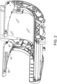
- Fig. 2 shows the basic structure of a seat having two arm rests with ventilation nozzles 20 according to the disclosure and Fig. 3 shows the seat from the opposite side. It is also within the scope of the disclosure that even for a seat with two arm rests, as shown, only one of the arm rests is provided with ventilation nozzles.
- the formation of the nozzles 20 in the side wall 41 of the arm rest 4a, 4b is shown in more detail in Fig. 4 .
- the arm rest 4a, 4b has a top surface 40 on which the person's arm may rest, in use. Additional cushioning 400 or a protective cover may be provided over the top surface to provide additional comfort or to provide a removable and replaceable surface that can be easily removed and replaced in the event of damage or the like.
- Side walls 41, 42 extend down from the top surface 40 to form an inner side wall 41 facing towards the seated person, and an outer side wall 42 facing away from the seated person.
- the cut away view of Fig. 4 shows the holler interior 10 of the arm rest defined by the top and side walls.
- the arms will also have a front facing end 43 and a rear end 44 attached to the structure of the seat 1.
- the conditioned air A from the air source (not shown - various sources are possible) is provided to the interior 10 of the arm rest e.g. via pipes or conduits (not shown).
- the way in which the air is provided to the arm rest is not important to this invention and various manners are conceivable.
- the nozzles 20 are formed extending through the inner side wall 41 such that the air in the interior 10 of the arm rest exits the nozzles through their outlets 22 to the area where the person is seated.
- the nozzles 20 should be formed at locations in the side wall where the exiting air will flow across the person's thighs and/or chest. The actual location will depend on the design and position of the armrest. Additional nozzles (not shown) may be formed in the top surface and/or the front end of the arm rest.
- the nozzles 20 may be circular such that the air exits in a straight path through the nozzle from its inlet 21 to its outlet 22.
- the path through the nozzles 20 can be formed with some directionality e.g. so that the air is directed more towards the back of the seat, or more towards the person's chest or neck area, for example, by the nozzles being shaped so that the inlets and the outlets are slightly offset.
- the nozzles 20 are formed in several rows across the side wall of the arm rest.
- the actual pattern, number and size of nozzles can be varied as required for any given situation.
- the system provided by this disclosure allows a more personal and comprehensive air conditioning to be achieved using standard seat components and already available space in arm rests in a simple, inexpensive manner.
Abstract
Description
- The present disclosure is concerned with providing conditioned air to a space around a seated person in e.g. but not exclusively, a vehicle or an aircraft or in another area where the person is seated in a seat and requires cooled and/or warmed air for health and/or comfort.
- Air conditioning systems are known in many fields to provide clean and comfortable air to people in enclosed spaces such as in rooms or vehicles.
- Aircraft cabins, for example, generally have their air temperature regulated for the safety and comfort of passengers by an environmental conditioning system (ECS) that is controlled to ensure that the cabin air is clean and fresh and at the required temperature. In addition, passengers have air vents or blowers in the panel above their heads to provide additional cooling to the individual passenger as required. Passengers in business class or first class seats may also have individual heaters/coolers positioned under their seats. These passengers are able to adjust the temperature of the environment around their seat individually.
- Whilst, as mentioned above, in aircraft the ECS operates to keep the cabin air comfortable, the fuel cost to cool the cabin air with conventional ECS systems is high. Where an aircraft is, for example, not full or where some passengers do not actually want or need the air temperature to be cooled to a given temperature, this is a wasted expense.
- Design consideration is currently being given to increasing the efficiency of aircraft systems including reducing the fuel consumed in operating the ECS. Various ECS systems have been developed that e.g. use recirculated cabin air or other methods to reduce fuel consumption. Another way of reducing fuel consumption of the ECS that is currently being considered is to allow the cabin temperature to actually be higher than has conventionally been selected, thus requiring less fuel in cooling the cabin temperature.
- A problem with this approach is that the higher cabin temperature might not be comfortable or optimal for every passenger.
- As mentioned above, in some aircraft, passengers in areas of the cabin where the passenger has a relatively large seat space e.g. in business or first class may have their own individual air conditioning devices. These are usually in the form of a heat exchanger unit for example as described above, mounted in a manifold and located under the passenger's seat. The manifold usually has a number of outlets for the cooled or warned air to exit to the seating area of the passenger. The manifold generally houses the heat exchanger components and has a flow channel for the air that has undergone heat exchange. The flow channel starts at an inlet which collects air from the heat exchanger, the channel then follows a circular path around the blower and has one or more outlets circumferentially offset with respect to the circular path from the inlet. The circular flow path may extend more than 360 degrees forming concentric circles around the blower. The overall width of the manifold is defined by the dimensions of the flow channel and the number for turns the channel makes around the blower - the more turns, the greater the width.
- In business class and first class or similar parts of the aircraft cabin, there is generally enough space under the seat for a manifold of large enough surface area to provide sufficient temperature control to the passenger. In other parts of the cabin, such as economy class, for example, the seats are less wide and there is not sufficient area under the seats for the sorts of units currently used in the higher/more expensive class seat areas. This means that it is not feasible to have such individual environment control units under every passenger seat and so it has not been feasible to introduce fuel saving ECSs in aircraft that result in a higher overall cabin air temperature.
- More compact heat exchanger systems are being developed that can be incorporated in other seat spaces. In addition, systems are being developed in which cooled (or warmed) air is channelled from the heat exchanger outlet through or behind the seat cushion forming the seat pad and/or back rest of the seat. Such systems can improve passenger comfort by providing comfortable temperatures where different parts of the person's body are located while the person is seated. This avoids one part of the person's body being cool and another part being warm.
- Even with such temperature controlled seats, however, if the general temperature of the aircraft cabin (or other space where the person is seated) is relatively high (or cold), those parts of the person's body not in direct contact with the seat - e.g. the person's knees, thighs, chest, etc. may experience a temperature substantially warner (or colder) than the rest of their body, which can cause discomfort.
- There is, therefore, a need for an improved air conditioning assembly that can provide warmed or cooled air from a heat exchanger outlet to parts of the person's body that are not in direct contact with the seat pad and back rest.
- According to one aspect, there is provided an air conditioning system for a seat, comprising an arm rest of the seat, the arm rest having a top side, and inner wall and an outer wall, a front end and a back end defining a hollow interior between them, means for providing air conditioned to a desired temperature, from a source to the hollow interior of the arm rest, and a plurality of nozzles formed through the inner wall, defined between a nozzle inlet on an inner surface of the inner wall facing into the hollow interior and a nozzle outlet on an outer surface of the inner wall facing towards a seating area of a person when sitting in the seat, the nozzles providing a path through which air flows from the hollow interior, into the nozzle inlet and out of the nozzle outlet.
- A conduit may direct air from a source of conditioned air into the hollow interior of the arm rest.
- The nozzles may be shaped e.g. to form a straight flow path from their nozzle inlet to their nozzle outlet. Other shapes are also possible, e.g. the nozzle inlets may be offset with respect to the nozzle outlets to define a directed flow path.
- One or more nozzles may also be formed through the top side and/or the front end of the arm rest.
- The nozzles may have various locations e.g. they may be arranged in a plurality of rows along the inner side wall.
- According to another aspect, there is provided a seat comprising a seat pad, a seat back and one or two arm rests defining between then a seating area for a person, and an air conditioning system as defined above for providing conditioned air to front parts of the body of a person sitting on the seat pad and resting against the back rest, via the plurality of nozzles. The air source may, for example, be located beneath the seat pad
- Non-limiting examples of assemblies according to the disclosure will now be described with reference to the drawings. It should be noted that variations are possible within the scope of the claims.
- The examples are described as used in an aircraft passenger seat, but the same principles can be used in seats in other settings or locations and the disclosure is not limited to aircraft seats.
-
Fig. 1 shows a seat incorporating an air conditioning system according to an example of the disclosure. -
Fig. 2 is a perspective partial view of a seat incorporating an air conditioning system according to an example of the disclosure. -
Fig. 3 shows the seat ofFig. 2 viewed from a different perspective. -
Fig. 4 shows a cut-away detailed view of seat armrests according to the disclosure. - The air conditioning system according to this disclosure makes use of the arm rest(s) of a seat to direct conditioned air inwards across the seat pad area such that the air is directed to the front of the body of a person sitting in the seat. The arm rest(s) of a seat are generally hollow and use can be made of the hollow space to incorporating one or more channels for the flow of conditioned air, the conditioned air is provided to the one or more channels in the arm rest(s) and outlet nozzles are provided in the side of the arm rest facing inwards towards the seating area of the seat where the seated person is located, the nozzles being shaped to eject conditioned air from the channel(s) in the arm rest(s) towards front parts of the person's body when seated e.g. the person's arms, knees, thighs and/or chest. Additional air nozzles may also be provided on other parts of the arm rest such as a top surface, where the user can rest their arm, and/or on the front end of the arm rest facing away from the seat back.
- Examples of the system of the disclosure will now be described in more detail with reference to
Figs. 1 to 4 . -
Figure 1 shows an example of aseat 1 having aseat pad 2 and aback rest 3 attached together such that the person sits on theseat pad 2 and their back rests against theback rest 3. The seat pad and the back rest can be adjustable relative to each other to allow for different seating positions to increasing the comfort of the person in the seat. Theseat pad 2 andback rest 3 are generally provided with cushioning to improving comfort but the concepts of this disclosure may also be used in a seat without any cushioning. - The
seat 1 is further provided with anarm rest seat pad 2 to allow the person seated in the seat to rest their arms in a comfortable position while seated. Although two arm rests 4a, 4b are shown, a seat may also be provided with only a single arm rest and/or may share an arm rest with an adjacent seat. - The position of the
arm rests seat pad 2. For example, the arm rest may be pivotable to an open positioned, in which it is pivoted up towards theback rest 3 e.g. to allow the person to easily get out of the seat. In addition, or alternatively, the height of thearm rest seat pad 2 to allow a comfortable rest position for persons of different side. Various shapes and sizes of arm rest are known. Arm rests can be contoured or shaped to be ergonomically advantageous or can be simply shaped where, for example, cost is a more important factor. Arm rests are commonly made of plastic material but other materials e.g. wood, metal etc. are also possible. Arm rests may be provided with a cushioned top surface to increase user comfort. - The seat is provided with an air conditioning system as described further below.
- Conditioned air A, from a source of conditioned air (not shown) is provided to the interior of the arm rest(s) 4a, 4b. The source of conditioned air may be a heat exchanger positioned beneath or behind or above or adjacent the
seat 1, but other sources are also feasible. The conditioned air may be conveyed from the source to the interior 10 of thearm rest seat pad 2 and/or into the back rest to provide a warming or cooling effect to the person's back in contact with theback rest 3. Whether the conditioned air is warm or cool will depend on the requirements of the person at any time, and on the environment, and will be determined by the conditioned air source or control, e.g. by the heat exchanger. If warming or cooling is also provided to the back of the person via theseat pad 2 and/or theback rest 3, it may be desired to provide a corresponding effect, at the same or closely similar temperature to the front of the person. - The conditioned air A either fills a hollow cavity or flows through one or more channels 5 in the
interior 10 of the arm rest and exits the arm rest via a plurality of openings ornozzles 20 formed through aside wall 41 of the arm rest that faces inwardly towards the seat area in which the person will be seated. The nozzles are shaped, located and directed in theside wall 41 so that the conditioned air can pass across the person's arms, knees, thighs and/or chest area when seated. The nozzles extend through theside wall 41 and are defined between anozzle inlet 21 on the inner surface of theside wall 41, facing into the interior of the arm rest, and anozzle outlet 22 defined in the outer surface of theside wall 41, facing into the seating area defined by theseat pad 2. -
Fig. 2 shows the basic structure of a seat having two arm rests withventilation nozzles 20 according to the disclosure andFig. 3 shows the seat from the opposite side. It is also within the scope of the disclosure that even for a seat with two arm rests, as shown, only one of the arm rests is provided with ventilation nozzles. - The formation of the
nozzles 20 in theside wall 41 of thearm rest Fig. 4 . Thearm rest top surface 40 on which the person's arm may rest, in use.Additional cushioning 400 or a protective cover may be provided over the top surface to provide additional comfort or to provide a removable and replaceable surface that can be easily removed and replaced in the event of damage or the like.Side walls top surface 40 to form aninner side wall 41 facing towards the seated person, and anouter side wall 42 facing away from the seated person. The cut away view ofFig. 4 shows theholler interior 10 of the arm rest defined by the top and side walls. - The arms will also have a front facing
end 43 and arear end 44 attached to the structure of theseat 1. - The conditioned air A from the air source (not shown - various sources are possible) is provided to the interior 10 of the arm rest e.g. via pipes or conduits (not shown). The way in which the air is provided to the arm rest is not important to this invention and various manners are conceivable.
- The
nozzles 20 are formed extending through theinner side wall 41 such that the air in theinterior 10 of the arm rest exits the nozzles through theiroutlets 22 to the area where the person is seated. Thenozzles 20 should be formed at locations in the side wall where the exiting air will flow across the person's thighs and/or chest. The actual location will depend on the design and position of the armrest. Additional nozzles (not shown) may be formed in the top surface and/or the front end of the arm rest. - The
nozzles 20 may be circular such that the air exits in a straight path through the nozzle from itsinlet 21 to itsoutlet 22. Alternatively, the path through thenozzles 20 can be formed with some directionality e.g. so that the air is directed more towards the back of the seat, or more towards the person's chest or neck area, for example, by the nozzles being shaped so that the inlets and the outlets are slightly offset. - In the example, the
nozzles 20 are formed in several rows across the side wall of the arm rest. The actual pattern, number and size of nozzles can be varied as required for any given situation. - The system provided by this disclosure allows a more personal and comprehensive air conditioning to be achieved using standard seat components and already available space in arm rests in a simple, inexpensive manner.
Claims (14)
- An air conditioning system for a seat, comprising an arm rest (4a, 4b) of the seat (1), the arm rest having a top side (40), and inner wall (41) and an outer wall (42), a front end (43) and a back end(44) defining a hollow interior (10) between them, means for providing air conditioned to a desired temperature, from a source to the hollow interior of the arm rest, and a plurality of nozzles (20) formed through the inner wall, defined between a nozzle inlet (21) on an inner surface of the inner wall facing into the hollow interior and a nozzle outlet (22) on an outer surface of the inner wall facing towards a seating area of a person when sitting in the seat, the nozzles providing a path through which air flows from the hollow interior, into the nozzle inlet and out of the nozzle outlet.
- The air conditioning system of claim 1, comprising a conduit to direct air from a source of conditioned air into the hollow interior of the arm rest.
- The air conditioning system of claim 1 or 2, wherein the nozzles are shaped to form a straight flow path from their nozzle inlet to their nozzle outlet.
- The air conditioning system of claim 1 or 2, wherein the nozzle inlets are offset with respect to the nozzle outlets to define a directed flow path.
- The air conditioning system of any preceding claim, further comprising one or more nozzles formed through the top side (40) of the arm rest.
- The air conditioning system of any preceding claim, further comprising one or more nozzles formed through the front end (43) of the arm rest.
- The air conditioning system of any preceding claim, further comprising a conditioned air source in fluid flow connection with the hollow interior of the arm rest.
- The air conditioning system of claim 7, wherein the conditioned air source comprises a heat exchanger.
- The air conditioning system of any proceeding claim, further comprising two arm rests (4a, 4b) on either side of the seating area, each arm rest having a top side, and inner wall and an outer wall, a front end and a back end defining a closed hollow interior between them, means for providing air conditioned to a desired temperature to the hollow interior of the arm rest, and a plurality of nozzles formed through the inner wall, defined between a nozzle inlet on an inner surface of the inner wall facing into the hollow interior and a nozzle outlet on an outer surface of the inner wall facing towards a seating area of a person when sitting in the seat, the nozzles providing a path through which airflows from the hollow interior, into the nozzle inlet and out of the nozzle outlet.
- The air conditioning system of any preceding claim, further comprising means for directing conditioned air from the source to a seat pad in the seating area.
- The air conditioning system of any preceding claim, further comprising means for directing conditioned air from the source to a seat back in the seating area.
- The air conditioning system of any preceding claim, wherein the nozzles are arranged in a plurality of rows along the inner side wall.
- A seat comprising a seat pad (2), a seat back (3) and one or two arm rests (4a, 4b) defining between then a seating area for a person, and an air conditioning system as claimed in any preceding claim for providing conditioned air to front parts of the body of a person sitting on the seat pad and resting against the back rest, via the plurality of nozzles.
- The seat of claim 13, wherein the air source is located beneath the seat pad.
Priority Applications (2)
| Application Number | Priority Date | Filing Date | Title |
|---|---|---|---|
| EP21461611.2A EP4173889A1 (en) | 2021-10-29 | 2021-10-29 | Air conditioning system for a seat |
| US17/964,665 US20230140582A1 (en) | 2021-10-29 | 2022-10-12 | Air conditioning system |
Applications Claiming Priority (1)
| Application Number | Priority Date | Filing Date | Title |
|---|---|---|---|
| EP21461611.2A EP4173889A1 (en) | 2021-10-29 | 2021-10-29 | Air conditioning system for a seat |
Publications (1)
| Publication Number | Publication Date |
|---|---|
| EP4173889A1 true EP4173889A1 (en) | 2023-05-03 |
Family
ID=78500574
Family Applications (1)
| Application Number | Title | Priority Date | Filing Date |
|---|---|---|---|
| EP21461611.2A Pending EP4173889A1 (en) | 2021-10-29 | 2021-10-29 | Air conditioning system for a seat |
Country Status (2)
| Country | Link |
|---|---|
| US (1) | US20230140582A1 (en) |
| EP (1) | EP4173889A1 (en) |
Citations (7)
| Publication number | Priority date | Publication date | Assignee | Title |
|---|---|---|---|---|
| JPH0357415A (en) * | 1989-07-26 | 1991-03-12 | Matsushita Electric Ind Co Ltd | Air conditioner |
| DE10241571A1 (en) * | 2002-09-07 | 2004-03-18 | Faurecia Autositze Gmbh & Co. Kg | Motor vehicle seat has air blowing nozzles installed on edge sections of seat section surface facing occupant and parallel and adjacent to side edges, with all nozzles orientated so that air jacket is formed round seat's occupant |
| JP2005255000A (en) * | 2004-03-11 | 2005-09-22 | Denso Corp | Air conditioner for vehicle |
| JP2006218902A (en) * | 2005-02-08 | 2006-08-24 | Shin Caterpillar Mitsubishi Ltd | Air conditioner for working machine |
| US20130299128A1 (en) * | 2010-10-28 | 2013-11-14 | Dimitri Bergamini | Air-conditioned seat for a cabin of a vehicle |
| US20180162243A1 (en) * | 2016-12-12 | 2018-06-14 | Toyota Boshoku Kabushiki Kaisha | Air conditioning seat |
| US20180361891A1 (en) * | 2017-06-19 | 2018-12-20 | Toyota Boshoku Kabushiki Kaisha | Vehicle air conditioning structure |
-
2021
- 2021-10-29 EP EP21461611.2A patent/EP4173889A1/en active Pending
-
2022
- 2022-10-12 US US17/964,665 patent/US20230140582A1/en active Pending
Patent Citations (7)
| Publication number | Priority date | Publication date | Assignee | Title |
|---|---|---|---|---|
| JPH0357415A (en) * | 1989-07-26 | 1991-03-12 | Matsushita Electric Ind Co Ltd | Air conditioner |
| DE10241571A1 (en) * | 2002-09-07 | 2004-03-18 | Faurecia Autositze Gmbh & Co. Kg | Motor vehicle seat has air blowing nozzles installed on edge sections of seat section surface facing occupant and parallel and adjacent to side edges, with all nozzles orientated so that air jacket is formed round seat's occupant |
| JP2005255000A (en) * | 2004-03-11 | 2005-09-22 | Denso Corp | Air conditioner for vehicle |
| JP2006218902A (en) * | 2005-02-08 | 2006-08-24 | Shin Caterpillar Mitsubishi Ltd | Air conditioner for working machine |
| US20130299128A1 (en) * | 2010-10-28 | 2013-11-14 | Dimitri Bergamini | Air-conditioned seat for a cabin of a vehicle |
| US20180162243A1 (en) * | 2016-12-12 | 2018-06-14 | Toyota Boshoku Kabushiki Kaisha | Air conditioning seat |
| US20180361891A1 (en) * | 2017-06-19 | 2018-12-20 | Toyota Boshoku Kabushiki Kaisha | Vehicle air conditioning structure |
Also Published As
| Publication number | Publication date |
|---|---|
| US20230140582A1 (en) | 2023-05-04 |
Similar Documents
| Publication | Publication Date | Title |
|---|---|---|
| JP7011678B2 (en) | Environmental control assembly | |
| US10252650B2 (en) | Vehicle seat with thermal comfort system | |
| US8539624B2 (en) | Structure based fluid distribution system | |
| US20120080911A1 (en) | Fluid distribution features for climate controlled seating assemblies | |
| US7708338B2 (en) | Ventilation system for seat | |
| EP2329988B1 (en) | Climate controlled seat assembly | |
| US10543761B2 (en) | Air supply component for use with a seat | |
| US20070001489A1 (en) | Vehicle seat with thermal elements | |
| CZ296176B6 (en) | Air-conditioning equipment of motor vehicles | |
| JP2007126047A (en) | Seat air conditioning device for vehicle | |
| US20220332227A1 (en) | Seat air-conditioner | |
| US20190283636A1 (en) | Vehicle air conditioning system | |
| EP4173889A1 (en) | Air conditioning system for a seat | |
| US20090042501A1 (en) | Localized Air Distribution System | |
| EP3892541B1 (en) | Personal heating ventilation and air conditioning system in aircraft seat | |
| JP2023008875A (en) | Ventilation assembly in aircraft | |
| CN215705838U (en) | Vehicle seat and vehicle | |
| JP2002127795A (en) | Child seat with air-conditioning function | |
| CN212373110U (en) | Vehicle air supply structure and car | |
| KR20200031351A (en) | Blower system for vechicle | |
| US11529843B2 (en) | Rear seat climate control | |
| KR20230059613A (en) | Individual vehicle air conditioning system using car seat structure | |
| KR20230032423A (en) | Ventilation apparatus installed in the seat of vehicles | |
| US10647231B2 (en) | Ventilated airline seating component | |
| KR20160139837A (en) | Seat for car with function of cold wind and warm wind |
Legal Events
| Date | Code | Title | Description |
|---|---|---|---|
| PUAI | Public reference made under article 153(3) epc to a published international application that has entered the european phase |
Free format text: ORIGINAL CODE: 0009012 |
|
| STAA | Information on the status of an ep patent application or granted ep patent |
Free format text: STATUS: THE APPLICATION HAS BEEN PUBLISHED |
|
| AK | Designated contracting states |
Kind code of ref document: A1 Designated state(s): AL AT BE BG CH CY CZ DE DK EE ES FI FR GB GR HR HU IE IS IT LI LT LU LV MC MK MT NL NO PL PT RO RS SE SI SK SM TR |
|
| P01 | Opt-out of the competence of the unified patent court (upc) registered |
Effective date: 20230922 |
|
| STAA | Information on the status of an ep patent application or granted ep patent |
Free format text: STATUS: REQUEST FOR EXAMINATION WAS MADE |
|
| 17P | Request for examination filed |
Effective date: 20231103 |
|
| RBV | Designated contracting states (corrected) |
Designated state(s): AL AT BE BG CH CY CZ DE DK EE ES FI FR GB GR HR HU IE IS IT LI LT LU LV MC MK MT NL NO PL PT RO RS SE SI SK SM TR |