EP3858409B1 - Vorrichtung zur messung der atemfrequenz - Google Patents
Vorrichtung zur messung der atemfrequenz Download PDFInfo
- Publication number
- EP3858409B1 EP3858409B1 EP19867937.5A EP19867937A EP3858409B1 EP 3858409 B1 EP3858409 B1 EP 3858409B1 EP 19867937 A EP19867937 A EP 19867937A EP 3858409 B1 EP3858409 B1 EP 3858409B1
- Authority
- EP
- European Patent Office
- Prior art keywords
- respiratory
- data
- pressure
- patient
- respiratory rate
- Prior art date
- Legal status (The legal status is an assumption and is not a legal conclusion. Google has not performed a legal analysis and makes no representation as to the accuracy of the status listed.)
- Active
Links
Images




Classifications
-
- A—HUMAN NECESSITIES
- A61—MEDICAL OR VETERINARY SCIENCE; HYGIENE
- A61M—DEVICES FOR INTRODUCING MEDIA INTO, OR ONTO, THE BODY; DEVICES FOR TRANSDUCING BODY MEDIA OR FOR TAKING MEDIA FROM THE BODY; DEVICES FOR PRODUCING OR ENDING SLEEP OR STUPOR
- A61M16/00—Devices for influencing the respiratory system of patients by gas treatment, e.g. ventilators; Tracheal tubes
- A61M16/021—Devices for influencing the respiratory system of patients by gas treatment, e.g. ventilators; Tracheal tubes operated by electrical means
- A61M16/022—Control means therefor
- A61M16/024—Control means therefor including calculation means, e.g. using a processor
- A61M16/026—Control means therefor including calculation means, e.g. using a processor specially adapted for predicting, e.g. for determining an information representative of a flow limitation during a ventilation cycle by using a root square technique or a regression analysis
-
- A—HUMAN NECESSITIES
- A61—MEDICAL OR VETERINARY SCIENCE; HYGIENE
- A61B—DIAGNOSIS; SURGERY; IDENTIFICATION
- A61B5/00—Measuring for diagnostic purposes; Identification of persons
- A61B5/08—Measuring devices for evaluating the respiratory organs
- A61B5/087—Measuring breath flow
-
- A—HUMAN NECESSITIES
- A61—MEDICAL OR VETERINARY SCIENCE; HYGIENE
- A61M—DEVICES FOR INTRODUCING MEDIA INTO, OR ONTO, THE BODY; DEVICES FOR TRANSDUCING BODY MEDIA OR FOR TAKING MEDIA FROM THE BODY; DEVICES FOR PRODUCING OR ENDING SLEEP OR STUPOR
- A61M16/00—Devices for influencing the respiratory system of patients by gas treatment, e.g. ventilators; Tracheal tubes
- A61M16/10—Preparation of respiratory gases or vapours
- A61M16/1005—Preparation of respiratory gases or vapours with O2 features or with parameter measurement
- A61M16/101—Preparation of respiratory gases or vapours with O2 features or with parameter measurement using an oxygen concentrator
-
- A—HUMAN NECESSITIES
- A61—MEDICAL OR VETERINARY SCIENCE; HYGIENE
- A61B—DIAGNOSIS; SURGERY; IDENTIFICATION
- A61B5/00—Measuring for diagnostic purposes; Identification of persons
- A61B5/08—Measuring devices for evaluating the respiratory organs
- A61B5/0816—Measuring devices for examining respiratory frequency
-
- A—HUMAN NECESSITIES
- A61—MEDICAL OR VETERINARY SCIENCE; HYGIENE
- A61B—DIAGNOSIS; SURGERY; IDENTIFICATION
- A61B5/00—Measuring for diagnostic purposes; Identification of persons
- A61B5/72—Signal processing specially adapted for physiological signals or for diagnostic purposes
- A61B5/7235—Details of waveform analysis
- A61B5/7246—Details of waveform analysis using correlation, e.g. template matching or determination of similarity
-
- A—HUMAN NECESSITIES
- A61—MEDICAL OR VETERINARY SCIENCE; HYGIENE
- A61M—DEVICES FOR INTRODUCING MEDIA INTO, OR ONTO, THE BODY; DEVICES FOR TRANSDUCING BODY MEDIA OR FOR TAKING MEDIA FROM THE BODY; DEVICES FOR PRODUCING OR ENDING SLEEP OR STUPOR
- A61M16/00—Devices for influencing the respiratory system of patients by gas treatment, e.g. ventilators; Tracheal tubes
- A61M16/0003—Accessories therefor, e.g. sensors, vibrators, negative pressure
-
- A—HUMAN NECESSITIES
- A61—MEDICAL OR VETERINARY SCIENCE; HYGIENE
- A61M—DEVICES FOR INTRODUCING MEDIA INTO, OR ONTO, THE BODY; DEVICES FOR TRANSDUCING BODY MEDIA OR FOR TAKING MEDIA FROM THE BODY; DEVICES FOR PRODUCING OR ENDING SLEEP OR STUPOR
- A61M16/00—Devices for influencing the respiratory system of patients by gas treatment, e.g. ventilators; Tracheal tubes
- A61M16/021—Devices for influencing the respiratory system of patients by gas treatment, e.g. ventilators; Tracheal tubes operated by electrical means
- A61M16/022—Control means therefor
- A61M16/024—Control means therefor including calculation means, e.g. using a processor
-
- B—PERFORMING OPERATIONS; TRANSPORTING
- B01—PHYSICAL OR CHEMICAL PROCESSES OR APPARATUS IN GENERAL
- B01D—SEPARATION
- B01D53/00—Separation of gases or vapours; Recovering vapours of volatile solvents from gases; Chemical or biological purification of waste gases, e.g. engine exhaust gases, smoke, fumes, flue gases, aerosols
- B01D53/02—Separation of gases or vapours; Recovering vapours of volatile solvents from gases; Chemical or biological purification of waste gases, e.g. engine exhaust gases, smoke, fumes, flue gases, aerosols by adsorption, e.g. preparative gas chromatography
- B01D53/04—Separation of gases or vapours; Recovering vapours of volatile solvents from gases; Chemical or biological purification of waste gases, e.g. engine exhaust gases, smoke, fumes, flue gases, aerosols by adsorption, e.g. preparative gas chromatography with stationary adsorbents
- B01D53/047—Pressure swing adsorption
-
- A—HUMAN NECESSITIES
- A61—MEDICAL OR VETERINARY SCIENCE; HYGIENE
- A61B—DIAGNOSIS; SURGERY; IDENTIFICATION
- A61B2505/00—Evaluating, monitoring or diagnosing in the context of a particular type of medical care
- A61B2505/07—Home care
-
- A—HUMAN NECESSITIES
- A61—MEDICAL OR VETERINARY SCIENCE; HYGIENE
- A61M—DEVICES FOR INTRODUCING MEDIA INTO, OR ONTO, THE BODY; DEVICES FOR TRANSDUCING BODY MEDIA OR FOR TAKING MEDIA FROM THE BODY; DEVICES FOR PRODUCING OR ENDING SLEEP OR STUPOR
- A61M16/00—Devices for influencing the respiratory system of patients by gas treatment, e.g. ventilators; Tracheal tubes
- A61M16/0057—Pumps therefor
- A61M16/0063—Compressors
-
- A—HUMAN NECESSITIES
- A61—MEDICAL OR VETERINARY SCIENCE; HYGIENE
- A61M—DEVICES FOR INTRODUCING MEDIA INTO, OR ONTO, THE BODY; DEVICES FOR TRANSDUCING BODY MEDIA OR FOR TAKING MEDIA FROM THE BODY; DEVICES FOR PRODUCING OR ENDING SLEEP OR STUPOR
- A61M16/00—Devices for influencing the respiratory system of patients by gas treatment, e.g. ventilators; Tracheal tubes
- A61M16/06—Respiratory or anaesthetic masks
- A61M16/0666—Nasal cannulas or tubing
- A61M16/0672—Nasal cannula assemblies for oxygen therapy
-
- A—HUMAN NECESSITIES
- A61—MEDICAL OR VETERINARY SCIENCE; HYGIENE
- A61M—DEVICES FOR INTRODUCING MEDIA INTO, OR ONTO, THE BODY; DEVICES FOR TRANSDUCING BODY MEDIA OR FOR TAKING MEDIA FROM THE BODY; DEVICES FOR PRODUCING OR ENDING SLEEP OR STUPOR
- A61M16/00—Devices for influencing the respiratory system of patients by gas treatment, e.g. ventilators; Tracheal tubes
- A61M16/10—Preparation of respiratory gases or vapours
- A61M16/14—Preparation of respiratory gases or vapours by mixing different fluids, one of them being in a liquid phase
- A61M16/16—Devices to humidify the respiration air
-
- A—HUMAN NECESSITIES
- A61—MEDICAL OR VETERINARY SCIENCE; HYGIENE
- A61M—DEVICES FOR INTRODUCING MEDIA INTO, OR ONTO, THE BODY; DEVICES FOR TRANSDUCING BODY MEDIA OR FOR TAKING MEDIA FROM THE BODY; DEVICES FOR PRODUCING OR ENDING SLEEP OR STUPOR
- A61M16/00—Devices for influencing the respiratory system of patients by gas treatment, e.g. ventilators; Tracheal tubes
- A61M16/20—Valves specially adapted to medical respiratory devices
- A61M16/201—Controlled valves
- A61M16/202—Controlled valves electrically actuated
-
- A—HUMAN NECESSITIES
- A61—MEDICAL OR VETERINARY SCIENCE; HYGIENE
- A61M—DEVICES FOR INTRODUCING MEDIA INTO, OR ONTO, THE BODY; DEVICES FOR TRANSDUCING BODY MEDIA OR FOR TAKING MEDIA FROM THE BODY; DEVICES FOR PRODUCING OR ENDING SLEEP OR STUPOR
- A61M16/00—Devices for influencing the respiratory system of patients by gas treatment, e.g. ventilators; Tracheal tubes
- A61M16/0003—Accessories therefor, e.g. sensors, vibrators, negative pressure
- A61M2016/0015—Accessories therefor, e.g. sensors, vibrators, negative pressure inhalation detectors
- A61M2016/0018—Accessories therefor, e.g. sensors, vibrators, negative pressure inhalation detectors electrical
- A61M2016/0021—Accessories therefor, e.g. sensors, vibrators, negative pressure inhalation detectors electrical with a proportional output signal, e.g. from a thermistor
-
- A—HUMAN NECESSITIES
- A61—MEDICAL OR VETERINARY SCIENCE; HYGIENE
- A61M—DEVICES FOR INTRODUCING MEDIA INTO, OR ONTO, THE BODY; DEVICES FOR TRANSDUCING BODY MEDIA OR FOR TAKING MEDIA FROM THE BODY; DEVICES FOR PRODUCING OR ENDING SLEEP OR STUPOR
- A61M16/00—Devices for influencing the respiratory system of patients by gas treatment, e.g. ventilators; Tracheal tubes
- A61M16/0003—Accessories therefor, e.g. sensors, vibrators, negative pressure
- A61M2016/0027—Accessories therefor, e.g. sensors, vibrators, negative pressure pressure meter
-
- A—HUMAN NECESSITIES
- A61—MEDICAL OR VETERINARY SCIENCE; HYGIENE
- A61M—DEVICES FOR INTRODUCING MEDIA INTO, OR ONTO, THE BODY; DEVICES FOR TRANSDUCING BODY MEDIA OR FOR TAKING MEDIA FROM THE BODY; DEVICES FOR PRODUCING OR ENDING SLEEP OR STUPOR
- A61M16/00—Devices for influencing the respiratory system of patients by gas treatment, e.g. ventilators; Tracheal tubes
- A61M16/0003—Accessories therefor, e.g. sensors, vibrators, negative pressure
- A61M2016/003—Accessories therefor, e.g. sensors, vibrators, negative pressure with a flowmeter
-
- A—HUMAN NECESSITIES
- A61—MEDICAL OR VETERINARY SCIENCE; HYGIENE
- A61M—DEVICES FOR INTRODUCING MEDIA INTO, OR ONTO, THE BODY; DEVICES FOR TRANSDUCING BODY MEDIA OR FOR TAKING MEDIA FROM THE BODY; DEVICES FOR PRODUCING OR ENDING SLEEP OR STUPOR
- A61M16/00—Devices for influencing the respiratory system of patients by gas treatment, e.g. ventilators; Tracheal tubes
- A61M16/0003—Accessories therefor, e.g. sensors, vibrators, negative pressure
- A61M2016/003—Accessories therefor, e.g. sensors, vibrators, negative pressure with a flowmeter
- A61M2016/0033—Accessories therefor, e.g. sensors, vibrators, negative pressure with a flowmeter electrical
- A61M2016/0039—Accessories therefor, e.g. sensors, vibrators, negative pressure with a flowmeter electrical in the inspiratory circuit
-
- A—HUMAN NECESSITIES
- A61—MEDICAL OR VETERINARY SCIENCE; HYGIENE
- A61M—DEVICES FOR INTRODUCING MEDIA INTO, OR ONTO, THE BODY; DEVICES FOR TRANSDUCING BODY MEDIA OR FOR TAKING MEDIA FROM THE BODY; DEVICES FOR PRODUCING OR ENDING SLEEP OR STUPOR
- A61M2202/00—Special media to be introduced, removed or treated
- A61M2202/02—Gases
- A61M2202/0208—Oxygen
-
- A—HUMAN NECESSITIES
- A61—MEDICAL OR VETERINARY SCIENCE; HYGIENE
- A61M—DEVICES FOR INTRODUCING MEDIA INTO, OR ONTO, THE BODY; DEVICES FOR TRANSDUCING BODY MEDIA OR FOR TAKING MEDIA FROM THE BODY; DEVICES FOR PRODUCING OR ENDING SLEEP OR STUPOR
- A61M2205/00—General characteristics of the apparatus
- A61M2205/33—Controlling, regulating or measuring
- A61M2205/3331—Pressure; Flow
-
- A—HUMAN NECESSITIES
- A61—MEDICAL OR VETERINARY SCIENCE; HYGIENE
- A61M—DEVICES FOR INTRODUCING MEDIA INTO, OR ONTO, THE BODY; DEVICES FOR TRANSDUCING BODY MEDIA OR FOR TAKING MEDIA FROM THE BODY; DEVICES FOR PRODUCING OR ENDING SLEEP OR STUPOR
- A61M2205/00—General characteristics of the apparatus
- A61M2205/50—General characteristics of the apparatus with microprocessors or computers
- A61M2205/502—User interfaces, e.g. screens or keyboards
-
- A—HUMAN NECESSITIES
- A61—MEDICAL OR VETERINARY SCIENCE; HYGIENE
- A61M—DEVICES FOR INTRODUCING MEDIA INTO, OR ONTO, THE BODY; DEVICES FOR TRANSDUCING BODY MEDIA OR FOR TAKING MEDIA FROM THE BODY; DEVICES FOR PRODUCING OR ENDING SLEEP OR STUPOR
- A61M2205/00—General characteristics of the apparatus
- A61M2205/50—General characteristics of the apparatus with microprocessors or computers
- A61M2205/52—General characteristics of the apparatus with microprocessors or computers with memories providing a history of measured variating parameters of apparatus or patient
-
- A—HUMAN NECESSITIES
- A61—MEDICAL OR VETERINARY SCIENCE; HYGIENE
- A61M—DEVICES FOR INTRODUCING MEDIA INTO, OR ONTO, THE BODY; DEVICES FOR TRANSDUCING BODY MEDIA OR FOR TAKING MEDIA FROM THE BODY; DEVICES FOR PRODUCING OR ENDING SLEEP OR STUPOR
- A61M2230/00—Measuring parameters of the user
- A61M2230/40—Respiratory characteristics
- A61M2230/42—Rate
-
- B—PERFORMING OPERATIONS; TRANSPORTING
- B01—PHYSICAL OR CHEMICAL PROCESSES OR APPARATUS IN GENERAL
- B01D—SEPARATION
- B01D2256/00—Main component in the product gas stream after treatment
- B01D2256/12—Oxygen
-
- B—PERFORMING OPERATIONS; TRANSPORTING
- B01—PHYSICAL OR CHEMICAL PROCESSES OR APPARATUS IN GENERAL
- B01D—SEPARATION
- B01D2259/00—Type of treatment
- B01D2259/40—Further details for adsorption processes and devices
- B01D2259/40007—Controlling pressure or temperature swing adsorption
-
- B—PERFORMING OPERATIONS; TRANSPORTING
- B01—PHYSICAL OR CHEMICAL PROCESSES OR APPARATUS IN GENERAL
- B01D—SEPARATION
- B01D2259/00—Type of treatment
- B01D2259/40—Further details for adsorption processes and devices
- B01D2259/40007—Controlling pressure or temperature swing adsorption
- B01D2259/40009—Controlling pressure or temperature swing adsorption using sensors or gas analysers
-
- B—PERFORMING OPERATIONS; TRANSPORTING
- B01—PHYSICAL OR CHEMICAL PROCESSES OR APPARATUS IN GENERAL
- B01D—SEPARATION
- B01D2259/00—Type of treatment
- B01D2259/45—Gas separation or purification devices adapted for specific applications
- B01D2259/4533—Gas separation or purification devices adapted for specific applications for medical purposes
Definitions
- the present disclosure relates to a respiratory rate measurement device used for a pressure swing adsorption oxygen concentration device.
- Oxygen therapy has been conventionally conducted as one medical treatment for patients suffering from respiratory diseases such as asthma and chronic obstructive pulmonary disease.
- respiratory diseases such as asthma and chronic obstructive pulmonary disease.
- the patients inhale oxygen gas or concentrated oxygen gas.
- HOT Home Oxygen Therapy
- the patients inhale oxygen e.g., at home or in facilities, aiming to improve the patients' QOL (Quality of Life)
- QOL Quality of Life
- the oxygen concentration device means a device that concentrates and delivers oxygen existing at about 21% in the air.
- Most oxygen concentration devices are generally of the pressure swing adsorption type (to be referred to as the PSA type hereinafter).
- the PSA oxygen concentration device repeatedly performs an adsorption process of introducing air into an adsorption column filled with an adsorbent for selectively adsorbing nitrogen gas, and pressurizing the adsorption column to adsorb the nitrogen gas to the adsorbent, and a desorption process of depressurizing the adsorption column to exhaust the adsorbed nitrogen gas out of the system. Repeating the adsorption and desorption processes generates concentrated oxygen gas to allow the oxygen concentration device to continuously provide highly concentrated oxygen gas to the patient.
- PSA A method for depressurizing the adsorption column to atmospheric pressure or less in the desorption process is sometimes called not PSA but, e.g., VPSA or VSA, but the basic principle of VPSA or VSA is the same as that of PSA, and these methods will therefore be collectively referred to as PSA hereinafter.
- COPD chronic obstructive pulmonary disease
- COPD COPD
- the respiratory rate can be measured even using, e.g., a stomach belt, but to know a long-term change in pathological condition of the patient, the patient is forced to bear a burden as, e.g., he or she may preferably wear the stomach belt at all times, or periodically with its wear always in mind. Generally, patients who receive home oxygen therapy are expected to periodically use the stomach belt for at least several hours each day. As long as a respiratory rate measurement device is built into or attached to an oxygen concentration device, a change in pathological condition during the use of the oxygen concentration device can be checked by the respiratory rate measurement device reliably, and without forcing the patient to bear an additional burden. The respiratory rate measurement device is very useful.
- a method for obtaining the respiratory rate of a patient which can be implemented in an oxygen concentration device
- a method is available for mounting a micro-differential pressure sensor for respiratory measurement between the oxygen concentration device and a cannula fitted to the patient to measure a patient respiratory pressure during oxygen inhalation, and recording the patient respiratory pressure on a recording medium or transmitting it as communication data, as disclosed in PTL 1.
- PTLs 2 and 4 disclose the fact that the respiratory rate and the like can be calculated from a respiratory pattern, but they describe no specific methods.
- PTL 3 discloses a method for storing the timings at which the pressure waveform changes from a fall to a rise and counting the respiratory rate, based on the interval between these timings, and a method for multiplying the amplitude of the pressure by a predetermined detection level ratio and determining that breathing is present only when a threshold corresponding to the calculated product is exceeded.
- PTL 5 discloses a method for calculating the respiratory rate by FFT (Fast Fourier Transform) processing or TDS processing.
- FFT Fast Fourier Transform
- PTL 6 discloses a method for measuring and storing pressure variations of an oxygen concentration device itself in advance, and subtracting the pressure variations from a detected pressure waveform.
- PTL 7 discloses an oxygen concentrator taking advantage of pressure swing adsorption.
- a flow rate sensor is used to determine the flow rate of gas flowing through the outlet system to the user.
- a pressure sensor is used to monitor the pressure of the gas passing through conduit to the user.
- a controller collects and stores the number of breaths. Based on the number of breaths, or the average time between breaths, over the period of time a breathing rate may be calculated.
- PTL 8 discloses analysing a photoplethysmograph (PPG) signal using autocorrelation sequence. e.
- the time between peaks of the combined autocorrelation sequence that are representative of the respiration information may be equivalent to the period of the respiration, which may be utilized to determine respiration rate (e.g., the frequency of respiration).
- the method for directly sending the calculated respiratory data has a drawback of, when an irregularity occurs in the respiratory waveform due to, e.g., noise or body movement, detecting a peak value or the like generated by the irregularity as breathing.
- the respiratory waveform considerably changes depending on the pathological condition of a patient who uses the respiratory rate measurement device, or the state of the patient, such as an active state or a sleep state, and even greatly varies in each individual patient. It is difficult to set a threshold as a criterion for breathing under a uniform rule, and determine whether breathing is present.
- the TDS processing poses a problem related to the influence of noise or body movement, a change in breathing that depends on the state of the patient, and differences in respiratory state for each individual patient.
- a respiratory rate measurement device has been invented to solve the above-described problems, and has as its exemplary object to make it possible to improve the measurement accuracy of the respiratory rate, with a PSA oxygen concentration device being used in combination.
- the respiratory rate measurement device can improve the measurement accuracy of the respiratory rate, without forcing the patient to bear an additional burden, with a PSA oxygen concentration device being used in combination.
- PSA oxygen concentration device implemented as an exemplary pressure swing adsorption oxygen concentration device, used in combination with a respiratory rate measurement device according to one aspect of an embodiment will be described below.
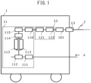
- Fig. 1 is a diagram illustrating an exemplary schematic configuration of a PSA oxygen concentration device.
- a PSA oxygen concentration device 1 includes an oxygen generation unit 11 that generates concentrated oxygen gas by introducing air A from the exterior of the PSA oxygen concentration device 1.
- the air A introduced from the exterior of the PSA oxygen device into the oxygen generation unit 11 is compressed by a compressor 111 and fed into an adsorption column 113 via a first switching valve 112.
- the first switching valve 112 connects the compressor 111 to one of adsorption columns 113 to feed the compressed air into the connected adsorption column 113, and opens the remaining adsorption columns to the atmosphere.
- the adsorption columns 113 are filled with adsorbents for selectively adsorbing nitrogen gas.
- the compressed air having passed through the adsorption column 113 reduces in nitrogen gas concentration and thus turns into concentrated oxygen gas.
- the concentrated oxygen gas is stored in a concentrated oxygen buffer tank 115 via a second switching valve 114.
- the second switching valve 114 connects or disconnects one of the adsorption columns 113 to or from the concentrated oxygen buffer tank 115.
- the oxygen generation unit 11 uses the first switching valve 112 to connect the compressor 111 to one of the adsorption columns 113, and uses the second switching valve 114 to connect the adsorption column 113 connected to the compressor 111 to the concentrated oxygen buffer tank 115. Therefore, the compressor 111, one of the adsorption columns 113, and the concentrated oxygen buffer tank 115 are connected to each other, and generated concentrated oxygen gas is supplied to the concentrated oxygen buffer tank 115.
- the adsorption columns 113 that are not connected to the compressor 111 are opened to the atmosphere via the first switching valve 112, as they are disconnected from the concentrated oxygen buffer tank 115 by the second switching valve 114. With this operation, the adsorption columns 113 are depressurized to exhaust the nitrogen gas adsorbed to the adsorbents out of the PSA oxygen concentration device 1.
- Opening and closing of the first switching valve 112 and the second switching valve 114 are controlled by, e.g., a microcomputer unit in a respiratory rate measurement device (not illustrated).
- the microcomputer unit can acquire a timing to switch between pressurization and depressurization in the adsorption columns 113.
- the respiratory rate measurement device may be placed in the oxygen concentration device 1, or may be placed outside the oxygen concentration device 1 separately from the oxygen concentration device 1.
- the oxygen concentration device 1 may include an oxygen concentration control unit that controls oxygen concentration processing including processing of opening and closing the first and second switching valves.
- the microcomputer unit can acquire a timing to switch between pressurization and depressurization in the adsorption columns 113 from the oxygen concentration control unit.
- the PSA oxygen concentration device 1 may connect two or more adsorption columns of the adsorption columns 113, in addition to the above-mentioned basic configuration.
- the PSA oxygen concentration device 1 may include an additional process such as a pressure equalization process of equalizing the pressures in the respective adsorption columns, or a purge process of refluxing part of the generated concentrated oxygen gas to one of the adsorption columns 113.
- the adsorption column 113 is opened to the atmosphere as it is disconnected from the compressor 111 by the first switching valve 112.
- any adsorption column 113 opened to the atmosphere is connected to the compressor 111 by the first switching valve 112, and shifts to the process of oxygen compression.
- the use of the first switching valve 112 to allow the adsorption columns 113 to alternately repeat compression and opening to the atmosphere makes it possible to continuously supply concentrated oxygen gas.
- the concentrated oxygen gas stored in the concentrated oxygen buffer tank 115 is regulated to attenuate the pressure variations by a pressure regulating valve 116.
- the concentrated oxygen gas having its pressure regulated by the oxygen generation unit 11 has its oxygen flow rate controlled by an oxygen flow control unit 12 formed by a control valve 121 and a flowmeter 122, and is supplied to the exterior of the oxygen concentration device by an oxygen supply port 13 via a humidifier 101.
- an oxygen flow control unit 12 formed by a control valve 121 and a flowmeter 122, and is supplied to the exterior of the oxygen concentration device by an oxygen supply port 13 via a humidifier 101.
- either the control valve 121 or the flowmeter 122 may be provided upstream in the flow path, and the oxygen flow control unit 12 may include other configurations or arrangements.
- the PSA oxygen concentration device 1 may include a switching fixed orifice for switching the flow rate, in place of the flowmeter 122 and the control valve 121.
- the PSA oxygen concentration device 1 may also use a scheme of manually controlling the flow rate using a visually-observable flowmeter such as a rotor meter as the flowmeter 122, and a manual flow control valve in place of the control valve 121, or may use other flow control schemes.
- the PSA oxygen concentration device 1 can even have a configuration equipped with no humidifier 101.
- Fig. 2 is a diagram illustrating an exemplary schematic configuration of a respiratory rate measurement device.
- Oxygen generated by the PSA oxygen concentration device 1 is supplied to the nasal cavity of a patient via a tube 2 connected to the PSA oxygen concentration device 1, and a nasal cannula 3 connected to the tube 2.
- the patient constantly breathes even during oxygen inhalation, and a pressure change occurring upon the breathing of the patient propagates toward the nasal cannula 3, the tube 2, and the PSA oxygen concentration device 1.
- a respiratory rate measurement device 4 is connected to the tube 2 serving as an oxygen supply path.
- the tube refers to one including the entire tube provided between the humidifier 101 (the oxygen flow control unit 12 when the PSA oxygen concentration device 1 is equipped with no humidifier 101) and the nasal cannula 3, and the respiratory rate measurement device 4 may be connected anywhere in the tube.
- a part or the whole of the respiratory rate measurement device 4 may be placed either inside or outside the PSA oxygen concentration device 1.
- pressure variations applied to the respiratory rate measurement device 4 include those occurring upon pressurization and depressurization during concentrated oxygen gas generation. Since the amplitude of the pressure variations occurring upon concentrated oxygen gas generation is larger than that of the respiratory pressure, and the amplitude of the respiratory pressure also reduces due to a pressure loss produced upon passage through the oxygen flow path, it is difficult to directly measure the respiratory pressure waveform of the patient from the pressure measured by the respiratory rate measurement device 4.
- the respiratory rate measurement device 4 includes a microcomputer unit 7 including an arithmetic operation unit and an estimation unit and connected to a pressure sensor 6.
- the pressure sensor 6 is preferably implemented as a micro-differential pressure sensor.
- the respiratory rate measurement device 4 preferably includes a display unit 8, such as a liquid crystal display, that displays the measured respiratory rate.
- the display unit 8 is connected to the microcomputer unit 7 and controlled by the microcomputer unit 7.
- the respiratory rate measurement device 4 includes, e.g., a pressure sensor 6, and preferably a micro-differential pressure sensor 6, as a detection unit that detects and outputs the pressure in the tube, and a microcomputer unit 7 electrically connected to the detection unit.
- the respiratory rate measurement device 4 may further include a positive-displacement unit connected to the micro-differential pressure sensor 6, and a pressure smoothing unit formed by an orifice 5 connecting the tube and the positive-displacement unit to each other.
- the reason why the pressure smoothing unit is provided is as follows.
- a sensor having the range of about ⁇ 100 Pa is preferably used as the micro-differential pressure sensor 6 to obtain the respiratory pressure by the respiratory rate measurement device 4.
- a supply pressure is constantly generated upon oxygen supply, and the supply pressure generated upon oxygen supply exists at, e.g., about 300 Pa even for 1 LPM (litter per minute: l/min).
- l/min peak per minute
- a pressure that falls within the measurement range of the micro-differential pressure sensor 6 may be preferably applied to the other end of the micro-differential pressure sensor 6, and a method for this operation is not limited to the example in this embodiment. As long as the measurement range of the micro-differential pressure sensor 6 is higher than the supply pressure generated upon oxygen supply, and a resolution high enough to allow detection of pressure variations occurring upon breathing of the patient can be ensured, the other end of the micro-differential pressure sensor 6 may even be opened to the atmosphere.
- a pressure sensor that measures a gauge pressure or an absolute pressure may be substituted for the micro-differential pressure sensor 6.
- the respiratory rate measurement device 4 may use a flow sensor in place of the pressure sensor 6.
- the respiratory rate measurement device 4 may even include both the pressure sensor 6 and the flow sensor.
- the pressure sensor 6 and/or the flow sensor serves as a detection unit that detects an in-tube pressure and/or an in-tube gas flow rate in the tube 2 including respiratory information of the patient, and outputs pressure data and/or in-tube gas flow rate data.
- Fig. 3 is a diagram illustrating an exemplary configuration block of the microcomputer unit 7.
- the microcomputer unit 7 including an arithmetic operation unit 722 and an estimation unit 723 is connected to the pressure sensor 6, and preferably the micro-differential pressure sensor 6.
- the arithmetic operation unit 722 and the estimation unit 723 obtain respiratory information of the patient by receiving the in-tube pressure data and or the in-tube gas flow rate data in the tube including the respiratory information of the patient, detected by the micro-differential pressure sensor 6 serving as the detection unit, and performing processing involved (to be described later).
- the microcomputer unit 7 may be implemented as the same microcomputer as in a processing unit that processes, e.g., an oxygen generation function and a display and user interface function for the oxygen concentration device, or may be separate from the processing unit.
- the microcomputer unit 7 acquires a timing to switch a PSA period T from a microcomputer that processes the oxygen generation function, and uses the acquired timing for arithmetic operation.
- the microcomputer unit 7 includes a storage unit 71 and a processing unit 72.
- the storage unit 71 is implemented as one or more semiconductor memories.
- the storage unit 71 includes at least one of nonvolatile memories such as a RAM, a flash memory, an EPROM, and an EEPROM.
- the storage unit 71 stores, e.g., a driver program, an operating system program, an application program, and data used for processing by the processing unit 72.
- the storage unit 71 stores, as the driver program, e.g., a device driver program for controlling, e.g., the micro-differential pressure sensor 6 serving as the detection unit.
- a computer program may be installed in the storage unit 71 using, e.g., a known setup program from a computer-readable portable recording medium such as a CD-ROM or a DVD-ROM.
- the computer program may even be downloaded from, e.g., a program server and installed.
- the storage unit 71 may further temporarily store temporary data associated with predetermined processing.
- the storage unit 71 stores, e.g., a threshold 711 and a variation value data file 712 for use in estimation of the respiratory rate.
- the processing unit 72 includes one or more processors and their peripheral circuits.
- the processing unit 72 systematically controls the overall operation of the respiratory rate measurement device 4, and is implemented as, e.g., an MCU (Micro Control Unit).
- MCU Micro Control Unit
- the processing unit 72 performs processing based on the programs (e.g., the operating system program, the driver program, and the application program) stored in the storage unit 71.
- the processing unit 72 may execute several programs (e.g., the application program) in parallel.
- the processing unit 72 includes, e.g., a detected data acquisition unit 721, the arithmetic operation unit 722, the estimation unit 723, and a respiratory rate output unit 724.
- Each of these units constituting the processing unit 72 may be implemented in the microcomputer unit 7 as an independent integrated circuit, circuit module, microprocessor, or firmware.
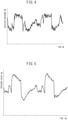
- Figs. 4, 5 , and 6 illustrate a group of data obtained when continuous flow is set at 5 LPM, and a 20-m extension tube is connected on the downstream side of the respiratory rate measurement device 4.
- the continuous flow means one concentrated oxygen gas supply scheme, in which concentrated oxygen gas is continuously supplied at a constant flow rate.
- Fig. 4 is a chart representing pressure data including respiratory information of the patient and PSA pressure data of the PSA oxygen concentration device 1, when continuous flow is set at 5 LPM, and a 20-m extension tube is connected.
- Fig. 5 is a chart representing PSA pressure data of the PSA oxygen concentration device 1 if the patient is not breathing or after respiratory components are removed, when continuous flow is set at 5 LPM, and a 20-m extension tube is connected.
- the PSA pressure obtained by the PSA oxygen concentration device means a periodical pressure change related to the adsorption column period of the PSA oxygen concentration device 1 and occurring when oxygen is generated by the PSA oxygen concentration device 1, as described above.
- the period of the waveform of the PSA pressure coincides with the adsorption column switching period of the PSA oxygen concentration device 1.
- Fig. 6 is a chart representing the result of subtraction processing of components illustrated in Fig. 5 from components illustrated in Fig. 4 by software.
- the subtraction processing means processing of computing the difference between two pieces of data at an arbitrary time instant.
- the respiratory rate measurement device 4 can remove PSA pressure components and detect a respiratory pressure in a patient respiratory model.
- the respiratory rate measurement device 4 can obtain respiratory information of the patient even in the state in which oxygen is continuously inhaled at 5 LPM from the PSA oxygen concentration device 1 via the nasal cannula and the 20-m extension tube.
- the method for measuring and storing pressure variations of an oxygen concentration device itself in advance, and subtracting the pressure variations from a detected pressure waveform may be used, or a method for subtracting pressure variations of an oxygen concentration device itself measured in real time from a detected pressure waveform may be used.
- the arithmetic operation unit 722 extracts respiratory information by calculating, as the pressure at a certain time t, the difference between a flow rate value Y(t) and a value X(t) obtained by averaging Y(t) and Y(t - T), Y(t - 2T),..., Y(t - nT) (n is a preset arbitrary integer). An original respiratory waveform having the PSA pressure components removed can thus be accurately reproduced.
- Fig. 7 is a conceptual diagram depicting arithmetic processing according to this embodiment.
- (I) illustrates a respiratory waveform
- (II) illustrates a model waveform for the PSA waveform.
- T denotes the period of the PSA waveform, which coincides with the switching period of the adsorption columns.
- (III) illustrates the sum of the waveforms illustrated in (I) and (II), and corresponds to the pressure measured in the tube portion.
- IV illustrates the result of dividing the waveform of (III) for each period T and superimposing the divided waveforms on each other. Unless the respiratory period and the PSA period completely coincide with each other, respiratory waveforms randomly appear in the waveforms divided by the periods T.
- V illustrates the result of averaging the waveforms superimposed on each other in (IV).
- variation value data X(t) representing a periodical pressure change and/or flow rate change of concentrated oxygen gas generated by the operation of the PSA oxygen concentration device is estimated by superimposition and averaging (V).
- (VI) illustrates a waveform obtained by subtracting the waveform of (V) from the portion corresponding to the last period T of the waveform of (III). This reveals that the original respiratory waveform (I) can be accurately reproduced.
- T the time from the start of the state in which one of the adsorption columns is connected to the compressor until a shift is made to the state in which another adsorption column is connected to the compressor may be selected.
- T the time from the start of the state in which one adsorption column is connected to the compressor, and then through the state in which the remaining adsorption columns are connected to the compressor, until a shift is made to the state in which the first adsorption column is connected to the compressor again may be selected.
- a multiple of each switching time may be selected as T.
- a moving average of five periods is used, but another method may be used for averaging.
- X(t) is the value after averaging processing at time t
- Y(t) is the actual measured value of the pressure at time t
- a i is a weighting coefficient in weighted averaging, which can be obtained by selecting an arbitrary real number
- n e -bi (b is an arbitrary positive real number)
- n ⁇
- n and a i also allows averaging processing that achieves more rapid convergence, such as an FIR (Finite Impulse Response) filter.
- Equation (1) is apparently seen as an equation for simply obtaining the time average of Y(t) by numerical computation.
- T a value sufficiently smaller than the variation period of Y(t)
- it is important to select, as T a value based on the adsorption and desorption period of a PSA process.
- a method for measuring the pressure has been exemplified as the respiratory rate measurement unit, but since the rate of flow through the tube also changes in response to the pressure variations in practice, a method for measuring the flow rate in place of the pressure can also be used.
- a method for measuring a pressure value and a flow rate value in combination or selectively, in accordance with the device operation conditions or environmental conditions, can even be used.
- the respiratory information obtained by arithmetic processing is so-called raw data, which represents real-time information of breathing such as the pressure or the flow rate in the form of a waveform.
- This data may be directly recorded or transmitted, but in this case, the amount of data is enormous, and it takes a long time for analysis. It is, therefore, desired to automatically calculate respiratory rate data in the respiratory rate measurement device 4, and then record and/or transmit it.
- a detectable respiratory waveform contains a large number of noise components generated upon, e.g., airflow-related pressure variations or cannula oscillation.
- the respiratory period and the respiratory rate may not be appropriately calculated either by peak detection for calculating the timings at which the pressure changes from a decrease to an increase, or by a method for detecting the timings at which a value equal to or larger than a threshold has been reached.
- respiratory waveforms to be counted appear as peaks indicated by a1, a2, and a3 in Fig. 6 and valleys appearing immediately after these peaks, and the remaining portions correspond to the noise components. Even when one attempts to detect these peaks as the timings at which the pressure changes from an increase to a decrease, it is highly probable that a portion indicated by b in Fig. 6 will be detected.
- the inventors of the present invention conducted a close examination, and found that the respiratory rate can be detected with high detection performance not by the above-mentioned method, but by calculating an autocorrelation coefficient between an original waveform and a waveform shifted from the original waveform by a time ⁇ t, and calculating ⁇ t, in which the autocorrelation coefficient takes a peak, while changing ⁇ t.
- These inventors also found a respiratory rate estimation method for estimating the respiratory rate per predetermined time from patient respiratory information.
- ⁇ t is the amount of shift in time
- t 0 is the data acquisition interval
- n is the number of data used for one computation operation of the autocorrelation coefficient
- f(t) is the value of patient respiratory information data at time t, which is acquired n times at the interval t 0 in computation
- ⁇ and ⁇ are the average and the standard deviation of f(t), but in actual computation, the average and the standard deviation of the n obtained values of f(t) may be used.
- the method for calculating the autocorrelation coefficient in this embodiment is merely an example, and other methods for calculating the autocorrelation coefficient may be used.
- the autocorrelation coefficient R calculated in this embodiment is multiplied by a normalization coefficient expressed as: 1 n ⁇ ⁇ t ⁇ 2 to define its value in the range of -1.0 to +1.0.
- Fig. 8 is a graph generated by plotting, with respect to ⁇ t, the computation result of the autocorrelation coefficient between the calculated waveform illustrated in Fig. 6 and the waveform obtained by shifting the original waveform along the time axis by the time ⁇ t, using the above-mentioned equation multiplied by the normalization coefficient.
- the autocorrelation coefficient is 1 because it represents the correlation between the original waveforms.
- points P1 and P2 are obtained as points having a high correlation.
- Fig. 8 reveals that even for a waveform that can hardly be used to determine the respiratory period either based on a threshold or by peak detection in raw patient respiratory information data, the respiratory period can easily be calculated by calculating the autocorrelation coefficient.
- the data interval of f(t) used to compute the autocorrelation coefficient is determined from the range of the respiratory period to be calculated.
- the inventors of the present invention conducted a close examination, and discovered that the data interval of f(t) may be preferably set twice or more a minimum respiratory period to be calculated.
- the respiratory rate of an average adult is about 12 to 20 breaths per minute, which corresponds to a respiratory period of about 3 to 5 seconds.
- the threshold of the autocorrelation coefficient for determining a peak of the autocorrelation coefficient may be preferably set to at least 0.3, and more preferably set in the range of 0.3 to 0.7. It was also found that setting the threshold below 0.3 increases the probability that an accidental rise in autocorrelation value due to, e.g., noise or baseline instability will be erroneously determined as a peak, and setting the threshold above 0.7 raises the probability that a rise in autocorrelation value corresponding to the respiratory period will be missed.
- the respiratory rate is calculated as the reciprocal of the respiratory interval that is the value of ⁇ t when the autocorrelation coefficient takes a certain value or more and a peak value. ⁇ t at the point P1 that is the first peak in Fig. 8 is determined as the respiratory interval, and dividing one minute by the respiratory interval yields a respiratory rate per minute.
- a plurality of points may be present as peaks having values equal to or larger than a certain value, as illustrated in Fig. 8 , but the right peak P2 is a peak corresponding to a multiple period appearing when ⁇ t is shifted by several breaths.
- the peak P1 located leftmost i.e., having the smallest value of ⁇ t, which is estimated to correspond to the basic period of breathing, may be preferably used.
- the computation described in this embodiment makes it possible to automatically accurately calculate respiratory rate information from the respiratory waveform obtained by the respiratory rate measurement unit connected to the concentrator.
- the estimation unit 723 can achieve a higher accuracy by calculating no respiratory rate when no wave having a magnitude high enough to determine that breathing is expected to be included is available.
- the determination of the presence or absence of breathing is not limited to determination based on the variance of the patient respiratory information data f(t), and may be performed using other determination methods.
- the threshold for variance evaluation in the use of the PSA oxygen concentration device is set as follows:
- Fig. 9 is a flowchart illustrating exemplary processing of extracting patient respiratory information data.
- the processing of extracting patient respiratory information data illustrated in Fig. 9 is performed by the microcomputer unit 7 in accordance with the computer program stored in the storage unit 71 in advance.
- the detected data acquisition unit 721 acquires pressure data Y(t) from the pressure sensor 6 serving as the detection unit (ST101).
- the arithmetic operation unit 722 calculates an average X(t) of Y(t) corresponding to n periods (ST102).
- the arithmetic operation unit 722 extracts patient respiratory information data f(t) by calculating the difference between Y(t) and X(t) (ST103).
- the arithmetic operation unit 722 does not perform the process of ST102, and extracts patient respiratory information data f(t) by calculating the difference between Y(t) and the PSA pressure variations measured and stored in advance, as ST103, after the process of ST101.
- processing of estimating the respiratory rate is repeatedly performed, so that patient respiratory information data f(t) is extracted and updated every time, for example, n pieces of measurement data of the pressures Y(t) are acquired at the interval t 0 .
- the patient respiratory information data f(t) may even be extracted at a predetermined interval and be updated.
- Fig. 10 is a flowchart illustrating exemplary processing of estimating the respiratory rate, based on the patient respiratory information data.
- the processing of estimating the respiratory rate illustrated in Fig. 10 is performed by the microcomputer unit 7 in accordance with the computer program stored in the storage unit 71 in advance.
- the estimation unit 723 calculates an average ⁇ and a standard deviation ⁇ of the patient respiratory information data f(t) (ST201).
- the estimation unit 723 determines whether the variance ⁇ 2 that is the square of the standard deviation ⁇ is equal to or higher than a predetermined threshold TH D (ST202).
- the respiratory rate output unit 724 outputs information indicating that computation has been impossible (ST213), and ends the process.
- the estimation unit 723 sets the time ⁇ t to zero (0) as the amount of shift in time (ST203).
- the estimation unit 723 increments the time ⁇ t by the data acquisition interval t 0 (ST204).
- the estimation unit 723 calculates an autocorrelation coefficient R( ⁇ t) of the patient respiratory information data f(t) for the time ⁇ t (ST205).
- the estimation unit 723 writes the calculated autocorrelation coefficient R( ⁇ t) into the storage unit 71 (ST206).
- the estimation unit 723 determines whether the time ⁇ t has reached nt 0 (ST207). When the time ⁇ t has not reached nt 0 , the process returns to ST203, in which estimation unit 723 repeats a series of processes (NO in ST207).
- the estimation unit 723 reads the autocorrelation coefficients R( ⁇ t) stored in the storage unit 71 (ST208). The estimation unit 723 compares the read autocorrelation coefficients R( ⁇ t) with each other to determine whether a maximum autocorrelation coefficient Max(R( ⁇ t)), i.e., a peak autocorrelation coefficient R( ⁇ t) is present (ST209). More specifically, the estimation unit 723 determines whether Max(R( ⁇ t)) is equal to or higher than a predetermined threshold THc.
- the estimation unit 723 sets the time ⁇ t for the maximum autocorrelation coefficient Max(R( ⁇ t)) as a respiratory interval (ST210).
- the estimation unit 723 estimates the respiratory rate from the respiratory interval ⁇ t (ST211).
- the respiratory rate output unit 724 outputs a respiratory rate signal (ST212), and ends the process.
- the display unit 8 upon receiving the respiratory rate signal, displays the respiratory rate.
- the respiratory rate output unit 724 When the maximum autocorrelation coefficient Max(R( ⁇ t)) is lower than the predetermined threshold THe (NO in ST209), the respiratory rate output unit 724 outputs information indicating that computation has been impossible (ST213), and ends the process.
- processing of estimating the respiratory rate is repeatedly performed, so that the respiratory rate measurement device 4 can update the respiratory rate and display it on the display unit 8.
- the display on the display unit 8 may be performed at a predetermined interval.
Landscapes
- Health & Medical Sciences (AREA)
- Life Sciences & Earth Sciences (AREA)
- Engineering & Computer Science (AREA)
- Pulmonology (AREA)
- Heart & Thoracic Surgery (AREA)
- Biomedical Technology (AREA)
- Animal Behavior & Ethology (AREA)
- General Health & Medical Sciences (AREA)
- Public Health (AREA)
- Veterinary Medicine (AREA)
- Emergency Medicine (AREA)
- Anesthesiology (AREA)
- Hematology (AREA)
- Physics & Mathematics (AREA)
- Physiology (AREA)
- Biophysics (AREA)
- Pathology (AREA)
- Medical Informatics (AREA)
- Molecular Biology (AREA)
- Surgery (AREA)
- Computer Vision & Pattern Recognition (AREA)
- Artificial Intelligence (AREA)
- Chemical & Material Sciences (AREA)
- Psychiatry (AREA)
- Signal Processing (AREA)
- Analytical Chemistry (AREA)
- General Chemical & Material Sciences (AREA)
- Oil, Petroleum & Natural Gas (AREA)
- Chemical Kinetics & Catalysis (AREA)
- Measurement Of The Respiration, Hearing Ability, Form, And Blood Characteristics Of Living Organisms (AREA)
Claims (6)
- Atemfrequenzmessvorrichtung (4), umfassend:eine Detektionseinheit (6), die dazu ausgelegt ist, einen Druck im Schlauch und/oder eine Gasdurchflussrate im Schlauch in einem Schlauch (2) zu erfassen, der einem Patienten konzentriertes Sauerstoffgas von einer Druckwechseladsorptions-Sauerstoffkonzentrationsvorrichtung (1) zuführt, die mit dem Patienten verbunden ist und Sauerstoff in der Luft durch periodische Wiederholung der Druckbeaufschlagung und Druckentlastung, und der Ausgabe von Druckdaten und/oder Gasdurchflussratendaten auszugeben;eine arithmetische Betriebseinheit (722), die dazu ausgelegt ist, Patienten-Atmungsinformationsdaten basierend auf den Druckdaten und/oder den Gasdurchflussratendaten zu extrahieren; undeine Schätzeinheit (723), die dazu ausgelegt ist, eine Atemfrequenz pro vorbestimmter Zeit basierend auf den Patienten-Atmungsinformationsdaten zu schätzen,dadurch gekennzeichnet, dass die arithmetische Betriebseinheit (722) dazu ausgelegt ist, Variationswertdaten zu schätzen, die eine periodische Druckänderung und/oder Durchflussratenänderung des konzentrierten Sauerstoffgases darstellen, die bei einem Betrieb einer Sauerstoffkonzentrationsvorrichtung auftreten, basierend auf den Druckdaten und/oder den Gasdurchflussratendaten, und die Patienten-Atmungsinformationsdaten zu extrahieren, indem die Variationswertdaten aus den Druckdaten und/oder den Gasdurchflussratendaten entfernt werden, und dassdie Schätzeinheit (723) ist dazu ausgelegt, einen Autokorrelationskoeffizienten zwischen den Patienten-Atmungsinformationsdaten und Daten, die von den Patienten-Ateminformationsdaten um eine Zeit Δt verschoben sind, zu berechnen, während die Zeit Δt geändert wird, und die Atemfrequenz zu schätzen, indem als Atemintervall eine Zeit Δt verwendet wird, in der der Autokorrelationskoeffizient einen Spitzenwert annimmt.
- Atemfrequenzmessvorrichtung (4) nach Anspruch 1, wobei die Schätzeinheit (723) dazu ausgelegt ist, die Atemfrequenz unter Verwendung einer Wellenform zu schätzen, die die Patienten-Ateminformationsdaten von mindestens 10 Sekunden anzeigt.
- Atemfrequenzmessvorrichtung nach Anspruch 1 oder 2, wobei die Schätzeinheit (723) dazu ausgelegt ist, einen Peak des Autokorrelationskoeffizienten, der einen vorbestimmten Schwellenwert überschreitet, zur Schätzung der Atemfrequenz zu verwenden.
- Atemfrequenzmessvorrichtung nach Anspruch 3, wobei der Schwellenwert einen Wert von 0,3 bis 0,7 annimmt.
- Atemfrequenzmessvorrichtung (4) nach Anspruch 3 oder 4, wobei Information, die anzeigt, dass eine Berechnung unmöglich war, ausgegeben wird, wenn ein Peak des Autokorrelationskoeffizienten, der den vorbestimmten Schwellenwert überschreitet, nicht erreicht wird.
- Atemfrequenzmessvorrichtung (4) nach einem der Ansprüche 1 bis 5, ferner umfassend eine Speichereinheit (71), die dazu ausgelegt ist, die im Voraus gemessenen Variationswertdaten zu speichern,
wobei die arithmetische Betriebseinheit (722) dazu ausgelegt ist, die Atmungsdaten des Patienten zu extrahieren, indem die Variationswertdaten aus den Druckdaten und/oder den Gasdurchflussratendaten entfernt werden.
Applications Claiming Priority (2)
| Application Number | Priority Date | Filing Date | Title |
|---|---|---|---|
| JP2018185785 | 2018-09-28 | ||
| PCT/JP2019/038359 WO2020067505A1 (ja) | 2018-09-28 | 2019-09-27 | 呼吸数計測装置 |
Publications (3)
| Publication Number | Publication Date |
|---|---|
| EP3858409A1 EP3858409A1 (de) | 2021-08-04 |
| EP3858409A4 EP3858409A4 (de) | 2022-06-29 |
| EP3858409B1 true EP3858409B1 (de) | 2024-05-08 |
Family
ID=69953176
Family Applications (1)
| Application Number | Title | Priority Date | Filing Date |
|---|---|---|---|
| EP19867937.5A Active EP3858409B1 (de) | 2018-09-28 | 2019-09-27 | Vorrichtung zur messung der atemfrequenz |
Country Status (7)
| Country | Link |
|---|---|
| US (1) | US20220031986A1 (de) |
| EP (1) | EP3858409B1 (de) |
| JP (1) | JP7055217B2 (de) |
| KR (1) | KR102526829B1 (de) |
| CN (1) | CN112739403B (de) |
| ES (1) | ES2980627T3 (de) |
| WO (1) | WO2020067505A1 (de) |
Families Citing this family (2)
| Publication number | Priority date | Publication date | Assignee | Title |
|---|---|---|---|---|
| CN115779209B (zh) * | 2022-11-21 | 2025-07-22 | 四川千里倍益康医疗科技股份有限公司 | 自适应海拔的脉冲式制氧机控制方法及脉冲式制氧机 |
| WO2025009542A1 (ja) * | 2023-07-04 | 2025-01-09 | 帝人ファーマ株式会社 | 呼吸数計測装置 |
Family Cites Families (21)
| Publication number | Priority date | Publication date | Assignee | Title |
|---|---|---|---|---|
| JP2994185B2 (ja) | 1992-10-13 | 1999-12-27 | 帝人株式会社 | 呼吸測定器、呼吸用気体供給装置及び呼吸モニタリングシステム |
| JP2994187B2 (ja) | 1993-09-30 | 1999-12-27 | 帝人株式会社 | 呼吸数測定装置、呼吸用気体供給装置及び呼吸モニタリングシステム |
| JP4416251B2 (ja) | 2000-02-14 | 2010-02-17 | 株式会社フクダ産業 | 医療用の濃縮酸素ガス供給装置 |
| JP2001266205A (ja) | 2000-03-22 | 2001-09-28 | Toshiba Corp | 磁気情報検出装置 |
| JP2002102187A (ja) | 2000-09-29 | 2002-04-09 | Matsushita Electric Ind Co Ltd | 生体検出装置 |
| JP2002336207A (ja) | 2001-05-14 | 2002-11-26 | Matsushita Electric Ind Co Ltd | 在床異常モニタ装置 |
| WO2005018789A2 (ja) * | 2003-08-26 | 2005-03-03 | Teijin Pharma Limited | 酸素濃縮装置 |
| US7011693B2 (en) * | 2003-11-12 | 2006-03-14 | General Motors Corporation | Control of a hydrogen purifying pressure swing adsorption unit in fuel processor module for hydrogen generation |
| FR2930165B1 (fr) | 2008-04-21 | 2010-08-20 | Air Liquide | Dispositif de detection de l'observance par un patient d'un traitement d'oxygenotherapie |
| MY165523A (en) * | 2009-08-13 | 2018-04-02 | Asanoi Hidetsugu | Device for calculating respiratory waveform information and medical instrument using respiratory waveform information |
| US10255647B2 (en) * | 2009-09-28 | 2019-04-09 | Caire Inc. | Controlling and communicating with respiratory care devices |
| JP5779186B2 (ja) * | 2009-11-16 | 2015-09-16 | レスメド・リミテッドResMedLimited | 睡眠時呼吸障害の適応性のある圧力治療のための方法及び装置 |
| JP5937476B2 (ja) | 2012-09-28 | 2016-06-22 | 帝人ファーマ株式会社 | 酸素供給装置 |
| US9440036B2 (en) * | 2012-10-12 | 2016-09-13 | InovaLabs, LLC | Method and systems for the delivery of oxygen enriched gas |
| JP6432970B2 (ja) | 2013-09-27 | 2018-12-05 | 公立大学法人奈良県立医科大学 | 呼吸監視装置及び呼吸監視方法 |
| GB2519964A (en) * | 2013-11-01 | 2015-05-13 | Linde Aktiengesellshcaft | Apparatus and method for detecting health deterioration |
| CA2932826A1 (en) * | 2014-02-20 | 2015-08-27 | Covidien Lp | Systems and methods for filtering autocorrelation peaks and detecting harmonics |
| US11071841B2 (en) * | 2015-06-22 | 2021-07-27 | Caire Inc. | Wearable oxygen generator and docking station enabling higher oxygen flow capacity |
| US11213643B2 (en) * | 2016-05-17 | 2022-01-04 | Fisher & Paykel Healthcare Limited | Flow path sensing for flow therapy apparatus |
| WO2018180392A1 (ja) | 2017-03-31 | 2018-10-04 | 帝人ファーマ株式会社 | 呼吸情報取得装置および呼吸情報取得方法 |
| JP2018180392A (ja) | 2017-04-18 | 2018-11-15 | 株式会社東芝 | 画像形成装置 |
-
2019
- 2019-09-27 ES ES19867937T patent/ES2980627T3/es active Active
- 2019-09-27 EP EP19867937.5A patent/EP3858409B1/de active Active
- 2019-09-27 US US17/279,215 patent/US20220031986A1/en not_active Abandoned
- 2019-09-27 CN CN201980063693.XA patent/CN112739403B/zh active Active
- 2019-09-27 WO PCT/JP2019/038359 patent/WO2020067505A1/ja not_active Ceased
- 2019-09-27 KR KR1020217009195A patent/KR102526829B1/ko active Active
- 2019-09-27 JP JP2020549479A patent/JP7055217B2/ja active Active
Also Published As
| Publication number | Publication date |
|---|---|
| EP3858409A4 (de) | 2022-06-29 |
| KR102526829B1 (ko) | 2023-04-27 |
| JP7055217B2 (ja) | 2022-04-15 |
| JPWO2020067505A1 (ja) | 2021-05-20 |
| ES2980627T3 (es) | 2024-10-02 |
| WO2020067505A1 (ja) | 2020-04-02 |
| EP3858409A1 (de) | 2021-08-04 |
| KR20210047936A (ko) | 2021-04-30 |
| US20220031986A1 (en) | 2022-02-03 |
| CN112739403A (zh) | 2021-04-30 |
| CN112739403B (zh) | 2024-04-30 |
Similar Documents
| Publication | Publication Date | Title |
|---|---|---|
| US11154256B2 (en) | Detecting mouth-breathing in early phase expiration | |
| EP2473106B1 (de) | System und verfahren zur quantifizierung der lungendehnbarkeit eines selbstatmenden patienten | |
| US20190192796A1 (en) | Ventilator with error detection for flow sensors | |
| EP3858407A1 (de) | Atemüberwachungsvorrichtung | |
| EP3858409A1 (de) | Vorrichtung zur messung der atemfrequenz | |
| EP3603712B1 (de) | Ateminformationserfassungsvorrichtung und ateminformationserfassungsverfahren | |
| JP6432970B2 (ja) | 呼吸監視装置及び呼吸監視方法 | |
| EP3858408B1 (de) | Vorrichtung zur erfassung von atmungsinformation | |
| US9649051B2 (en) | Method and system for analyzing a patients respiratory activity and corresponding uses |
Legal Events
| Date | Code | Title | Description |
|---|---|---|---|
| STAA | Information on the status of an ep patent application or granted ep patent |
Free format text: STATUS: THE INTERNATIONAL PUBLICATION HAS BEEN MADE |
|
| PUAI | Public reference made under article 153(3) epc to a published international application that has entered the european phase |
Free format text: ORIGINAL CODE: 0009012 |
|
| STAA | Information on the status of an ep patent application or granted ep patent |
Free format text: STATUS: REQUEST FOR EXAMINATION WAS MADE |
|
| 17P | Request for examination filed |
Effective date: 20210325 |
|
| AK | Designated contracting states |
Kind code of ref document: A1 Designated state(s): AL AT BE BG CH CY CZ DE DK EE ES FI FR GB GR HR HU IE IS IT LI LT LU LV MC MK MT NL NO PL PT RO RS SE SI SK SM TR |
|
| DAV | Request for validation of the european patent (deleted) | ||
| DAX | Request for extension of the european patent (deleted) | ||
| A4 | Supplementary search report drawn up and despatched |
Effective date: 20220527 |
|
| RIC1 | Information provided on ipc code assigned before grant |
Ipc: B01D 53/047 20060101ALI20220520BHEP Ipc: A61M 16/16 20060101ALI20220520BHEP Ipc: A61B 5/08 20060101ALI20220520BHEP Ipc: A61B 5/00 20060101ALI20220520BHEP Ipc: A61M 16/10 20060101ALI20220520BHEP Ipc: A61B 5/087 20060101ALI20220520BHEP Ipc: A61M 16/00 20060101AFI20220520BHEP |
|
| GRAP | Despatch of communication of intention to grant a patent |
Free format text: ORIGINAL CODE: EPIDOSNIGR1 |
|
| STAA | Information on the status of an ep patent application or granted ep patent |
Free format text: STATUS: GRANT OF PATENT IS INTENDED |
|
| RIC1 | Information provided on ipc code assigned before grant |
Ipc: B01D 53/047 20060101ALI20231116BHEP Ipc: A61M 16/16 20060101ALI20231116BHEP Ipc: A61B 5/08 20060101ALI20231116BHEP Ipc: A61B 5/00 20060101ALI20231116BHEP Ipc: A61M 16/10 20060101ALI20231116BHEP Ipc: A61B 5/087 20060101ALI20231116BHEP Ipc: A61M 16/00 20060101AFI20231116BHEP |
|
| INTG | Intention to grant announced |
Effective date: 20231211 |
|
| GRAS | Grant fee paid |
Free format text: ORIGINAL CODE: EPIDOSNIGR3 |
|
| GRAA | (expected) grant |
Free format text: ORIGINAL CODE: 0009210 |
|
| STAA | Information on the status of an ep patent application or granted ep patent |
Free format text: STATUS: THE PATENT HAS BEEN GRANTED |
|
| AK | Designated contracting states |
Kind code of ref document: B1 Designated state(s): AL AT BE BG CH CY CZ DE DK EE ES FI FR GB GR HR HU IE IS IT LI LT LU LV MC MK MT NL NO PL PT RO RS SE SI SK SM TR |
|
| REG | Reference to a national code |
Ref country code: GB Ref legal event code: FG4D |
|
| REG | Reference to a national code |
Ref country code: CH Ref legal event code: EP |
|
| REG | Reference to a national code |
Ref country code: DE Ref legal event code: R096 Ref document number: 602019052077 Country of ref document: DE |
|
| REG | Reference to a national code |
Ref country code: IE Ref legal event code: FG4D |
|
| REG | Reference to a national code |
Ref country code: LT Ref legal event code: MG9D |
|
| REG | Reference to a national code |
Ref country code: NL Ref legal event code: MP Effective date: 20240508 |
|
| REG | Reference to a national code |
Ref country code: ES Ref legal event code: FG2A Ref document number: 2980627 Country of ref document: ES Kind code of ref document: T3 Effective date: 20241002 |
|
| PG25 | Lapsed in a contracting state [announced via postgrant information from national office to epo] |
Ref country code: IS Free format text: LAPSE BECAUSE OF FAILURE TO SUBMIT A TRANSLATION OF THE DESCRIPTION OR TO PAY THE FEE WITHIN THE PRESCRIBED TIME-LIMIT Effective date: 20240908 |
|
| PG25 | Lapsed in a contracting state [announced via postgrant information from national office to epo] |
Ref country code: BG Free format text: LAPSE BECAUSE OF FAILURE TO SUBMIT A TRANSLATION OF THE DESCRIPTION OR TO PAY THE FEE WITHIN THE PRESCRIBED TIME-LIMIT Effective date: 20240508 |
|
| PG25 | Lapsed in a contracting state [announced via postgrant information from national office to epo] |
Ref country code: HR Free format text: LAPSE BECAUSE OF FAILURE TO SUBMIT A TRANSLATION OF THE DESCRIPTION OR TO PAY THE FEE WITHIN THE PRESCRIBED TIME-LIMIT Effective date: 20240508 Ref country code: FI Free format text: LAPSE BECAUSE OF FAILURE TO SUBMIT A TRANSLATION OF THE DESCRIPTION OR TO PAY THE FEE WITHIN THE PRESCRIBED TIME-LIMIT Effective date: 20240508 |
|
| PG25 | Lapsed in a contracting state [announced via postgrant information from national office to epo] |
Ref country code: GR Free format text: LAPSE BECAUSE OF FAILURE TO SUBMIT A TRANSLATION OF THE DESCRIPTION OR TO PAY THE FEE WITHIN THE PRESCRIBED TIME-LIMIT Effective date: 20240809 |
|
| PG25 | Lapsed in a contracting state [announced via postgrant information from national office to epo] |
Ref country code: PT Free format text: LAPSE BECAUSE OF FAILURE TO SUBMIT A TRANSLATION OF THE DESCRIPTION OR TO PAY THE FEE WITHIN THE PRESCRIBED TIME-LIMIT Effective date: 20240909 |
|
| REG | Reference to a national code |
Ref country code: AT Ref legal event code: MK05 Ref document number: 1684495 Country of ref document: AT Kind code of ref document: T Effective date: 20240508 |
|
| PG25 | Lapsed in a contracting state [announced via postgrant information from national office to epo] |
Ref country code: NL Free format text: LAPSE BECAUSE OF FAILURE TO SUBMIT A TRANSLATION OF THE DESCRIPTION OR TO PAY THE FEE WITHIN THE PRESCRIBED TIME-LIMIT Effective date: 20240508 |
|
| PG25 | Lapsed in a contracting state [announced via postgrant information from national office to epo] |
Ref country code: AT Free format text: LAPSE BECAUSE OF FAILURE TO SUBMIT A TRANSLATION OF THE DESCRIPTION OR TO PAY THE FEE WITHIN THE PRESCRIBED TIME-LIMIT Effective date: 20240508 |
|
| PG25 | Lapsed in a contracting state [announced via postgrant information from national office to epo] |
Ref country code: PL Free format text: LAPSE BECAUSE OF FAILURE TO SUBMIT A TRANSLATION OF THE DESCRIPTION OR TO PAY THE FEE WITHIN THE PRESCRIBED TIME-LIMIT Effective date: 20240508 |
|
| PG25 | Lapsed in a contracting state [announced via postgrant information from national office to epo] |
Ref country code: LV Free format text: LAPSE BECAUSE OF FAILURE TO SUBMIT A TRANSLATION OF THE DESCRIPTION OR TO PAY THE FEE WITHIN THE PRESCRIBED TIME-LIMIT Effective date: 20240508 |
|
| PG25 | Lapsed in a contracting state [announced via postgrant information from national office to epo] |
Ref country code: PT Free format text: LAPSE BECAUSE OF FAILURE TO SUBMIT A TRANSLATION OF THE DESCRIPTION OR TO PAY THE FEE WITHIN THE PRESCRIBED TIME-LIMIT Effective date: 20240909 Ref country code: PL Free format text: LAPSE BECAUSE OF FAILURE TO SUBMIT A TRANSLATION OF THE DESCRIPTION OR TO PAY THE FEE WITHIN THE PRESCRIBED TIME-LIMIT Effective date: 20240508 Ref country code: NO Free format text: LAPSE BECAUSE OF FAILURE TO SUBMIT A TRANSLATION OF THE DESCRIPTION OR TO PAY THE FEE WITHIN THE PRESCRIBED TIME-LIMIT Effective date: 20240808 Ref country code: NL Free format text: LAPSE BECAUSE OF FAILURE TO SUBMIT A TRANSLATION OF THE DESCRIPTION OR TO PAY THE FEE WITHIN THE PRESCRIBED TIME-LIMIT Effective date: 20240508 Ref country code: LV Free format text: LAPSE BECAUSE OF FAILURE TO SUBMIT A TRANSLATION OF THE DESCRIPTION OR TO PAY THE FEE WITHIN THE PRESCRIBED TIME-LIMIT Effective date: 20240508 Ref country code: IS Free format text: LAPSE BECAUSE OF FAILURE TO SUBMIT A TRANSLATION OF THE DESCRIPTION OR TO PAY THE FEE WITHIN THE PRESCRIBED TIME-LIMIT Effective date: 20240908 Ref country code: HR Free format text: LAPSE BECAUSE OF FAILURE TO SUBMIT A TRANSLATION OF THE DESCRIPTION OR TO PAY THE FEE WITHIN THE PRESCRIBED TIME-LIMIT Effective date: 20240508 Ref country code: GR Free format text: LAPSE BECAUSE OF FAILURE TO SUBMIT A TRANSLATION OF THE DESCRIPTION OR TO PAY THE FEE WITHIN THE PRESCRIBED TIME-LIMIT Effective date: 20240809 Ref country code: FI Free format text: LAPSE BECAUSE OF FAILURE TO SUBMIT A TRANSLATION OF THE DESCRIPTION OR TO PAY THE FEE WITHIN THE PRESCRIBED TIME-LIMIT Effective date: 20240508 Ref country code: BG Free format text: LAPSE BECAUSE OF FAILURE TO SUBMIT A TRANSLATION OF THE DESCRIPTION OR TO PAY THE FEE WITHIN THE PRESCRIBED TIME-LIMIT Effective date: 20240508 Ref country code: AT Free format text: LAPSE BECAUSE OF FAILURE TO SUBMIT A TRANSLATION OF THE DESCRIPTION OR TO PAY THE FEE WITHIN THE PRESCRIBED TIME-LIMIT Effective date: 20240508 Ref country code: RS Free format text: LAPSE BECAUSE OF FAILURE TO SUBMIT A TRANSLATION OF THE DESCRIPTION OR TO PAY THE FEE WITHIN THE PRESCRIBED TIME-LIMIT Effective date: 20240808 |
|
| PG25 | Lapsed in a contracting state [announced via postgrant information from national office to epo] |
Ref country code: DK Free format text: LAPSE BECAUSE OF FAILURE TO SUBMIT A TRANSLATION OF THE DESCRIPTION OR TO PAY THE FEE WITHIN THE PRESCRIBED TIME-LIMIT Effective date: 20240508 |
|
| PG25 | Lapsed in a contracting state [announced via postgrant information from national office to epo] |
Ref country code: EE Free format text: LAPSE BECAUSE OF FAILURE TO SUBMIT A TRANSLATION OF THE DESCRIPTION OR TO PAY THE FEE WITHIN THE PRESCRIBED TIME-LIMIT Effective date: 20240508 |
|
| PG25 | Lapsed in a contracting state [announced via postgrant information from national office to epo] |
Ref country code: CZ Free format text: LAPSE BECAUSE OF FAILURE TO SUBMIT A TRANSLATION OF THE DESCRIPTION OR TO PAY THE FEE WITHIN THE PRESCRIBED TIME-LIMIT Effective date: 20240508 |
|
| PG25 | Lapsed in a contracting state [announced via postgrant information from national office to epo] |
Ref country code: SK Free format text: LAPSE BECAUSE OF FAILURE TO SUBMIT A TRANSLATION OF THE DESCRIPTION OR TO PAY THE FEE WITHIN THE PRESCRIBED TIME-LIMIT Effective date: 20240508 Ref country code: RO Free format text: LAPSE BECAUSE OF FAILURE TO SUBMIT A TRANSLATION OF THE DESCRIPTION OR TO PAY THE FEE WITHIN THE PRESCRIBED TIME-LIMIT Effective date: 20240508 |
|
| PG25 | Lapsed in a contracting state [announced via postgrant information from national office to epo] |
Ref country code: SM Free format text: LAPSE BECAUSE OF FAILURE TO SUBMIT A TRANSLATION OF THE DESCRIPTION OR TO PAY THE FEE WITHIN THE PRESCRIBED TIME-LIMIT Effective date: 20240508 |
|
| PG25 | Lapsed in a contracting state [announced via postgrant information from national office to epo] |
Ref country code: SM Free format text: LAPSE BECAUSE OF FAILURE TO SUBMIT A TRANSLATION OF THE DESCRIPTION OR TO PAY THE FEE WITHIN THE PRESCRIBED TIME-LIMIT Effective date: 20240508 Ref country code: SK Free format text: LAPSE BECAUSE OF FAILURE TO SUBMIT A TRANSLATION OF THE DESCRIPTION OR TO PAY THE FEE WITHIN THE PRESCRIBED TIME-LIMIT Effective date: 20240508 Ref country code: RO Free format text: LAPSE BECAUSE OF FAILURE TO SUBMIT A TRANSLATION OF THE DESCRIPTION OR TO PAY THE FEE WITHIN THE PRESCRIBED TIME-LIMIT Effective date: 20240508 Ref country code: EE Free format text: LAPSE BECAUSE OF FAILURE TO SUBMIT A TRANSLATION OF THE DESCRIPTION OR TO PAY THE FEE WITHIN THE PRESCRIBED TIME-LIMIT Effective date: 20240508 Ref country code: DK Free format text: LAPSE BECAUSE OF FAILURE TO SUBMIT A TRANSLATION OF THE DESCRIPTION OR TO PAY THE FEE WITHIN THE PRESCRIBED TIME-LIMIT Effective date: 20240508 Ref country code: CZ Free format text: LAPSE BECAUSE OF FAILURE TO SUBMIT A TRANSLATION OF THE DESCRIPTION OR TO PAY THE FEE WITHIN THE PRESCRIBED TIME-LIMIT Effective date: 20240508 |
|
| REG | Reference to a national code |
Ref country code: DE Ref legal event code: R097 Ref document number: 602019052077 Country of ref document: DE |
|
| PLBE | No opposition filed within time limit |
Free format text: ORIGINAL CODE: 0009261 |
|
| STAA | Information on the status of an ep patent application or granted ep patent |
Free format text: STATUS: NO OPPOSITION FILED WITHIN TIME LIMIT |
|
| 26N | No opposition filed |
Effective date: 20250211 |
|
| PG25 | Lapsed in a contracting state [announced via postgrant information from national office to epo] |
Ref country code: MC Free format text: LAPSE BECAUSE OF FAILURE TO SUBMIT A TRANSLATION OF THE DESCRIPTION OR TO PAY THE FEE WITHIN THE PRESCRIBED TIME-LIMIT Effective date: 20240508 Ref country code: SI Free format text: LAPSE BECAUSE OF FAILURE TO SUBMIT A TRANSLATION OF THE DESCRIPTION OR TO PAY THE FEE WITHIN THE PRESCRIBED TIME-LIMIT Effective date: 20240508 |
|
| REG | Reference to a national code |
Ref country code: CH Ref legal event code: PL |
|
| PG25 | Lapsed in a contracting state [announced via postgrant information from national office to epo] |
Ref country code: LU Free format text: LAPSE BECAUSE OF NON-PAYMENT OF DUE FEES Effective date: 20240927 |
|
| GBPC | Gb: european patent ceased through non-payment of renewal fee |
Effective date: 20240927 |
|
| PG25 | Lapsed in a contracting state [announced via postgrant information from national office to epo] |
Ref country code: GB Free format text: LAPSE BECAUSE OF NON-PAYMENT OF DUE FEES Effective date: 20240927 |
|
| REG | Reference to a national code |
Ref country code: BE Ref legal event code: MM Effective date: 20240930 |
|
| PG25 | Lapsed in a contracting state [announced via postgrant information from national office to epo] |
Ref country code: BE Free format text: LAPSE BECAUSE OF NON-PAYMENT OF DUE FEES Effective date: 20240930 |
|
| PG25 | Lapsed in a contracting state [announced via postgrant information from national office to epo] |
Ref country code: CH Free format text: LAPSE BECAUSE OF NON-PAYMENT OF DUE FEES Effective date: 20240930 |
|
| PG25 | Lapsed in a contracting state [announced via postgrant information from national office to epo] |
Ref country code: IE Free format text: LAPSE BECAUSE OF NON-PAYMENT OF DUE FEES Effective date: 20240927 |
|
| PG25 | Lapsed in a contracting state [announced via postgrant information from national office to epo] |
Ref country code: SE Free format text: LAPSE BECAUSE OF FAILURE TO SUBMIT A TRANSLATION OF THE DESCRIPTION OR TO PAY THE FEE WITHIN THE PRESCRIBED TIME-LIMIT Effective date: 20240508 |
|
| PGFP | Annual fee paid to national office [announced via postgrant information from national office to epo] |
Ref country code: DE Payment date: 20250919 Year of fee payment: 7 |
|
| PGFP | Annual fee paid to national office [announced via postgrant information from national office to epo] |
Ref country code: IT Payment date: 20250923 Year of fee payment: 7 |
|
| PGFP | Annual fee paid to national office [announced via postgrant information from national office to epo] |
Ref country code: FR Payment date: 20250922 Year of fee payment: 7 |
|
| REG | Reference to a national code |
Ref country code: DE Ref legal event code: R081 Ref document number: 602019052077 Country of ref document: DE Owner name: TEIJIN LIMITED, OSAKA-SHI, JP Free format text: FORMER OWNER: TEIJIN PHARMA LIMITED, TOKYO, JP |
|
| PG25 | Lapsed in a contracting state [announced via postgrant information from national office to epo] |
Ref country code: CY Free format text: LAPSE BECAUSE OF FAILURE TO SUBMIT A TRANSLATION OF THE DESCRIPTION OR TO PAY THE FEE WITHIN THE PRESCRIBED TIME-LIMIT; INVALID AB INITIO Effective date: 20190927 |
|
| PGFP | Annual fee paid to national office [announced via postgrant information from national office to epo] |
Ref country code: ES Payment date: 20251030 Year of fee payment: 7 |
|
| PG25 | Lapsed in a contracting state [announced via postgrant information from national office to epo] |
Ref country code: HU Free format text: LAPSE BECAUSE OF FAILURE TO SUBMIT A TRANSLATION OF THE DESCRIPTION OR TO PAY THE FEE WITHIN THE PRESCRIBED TIME-LIMIT; INVALID AB INITIO Effective date: 20190927 |