EP3858142B1 - Automated removal of animal carcasses - Google Patents
Automated removal of animal carcasses Download PDFInfo
- Publication number
- EP3858142B1 EP3858142B1 EP20155022.5A EP20155022A EP3858142B1 EP 3858142 B1 EP3858142 B1 EP 3858142B1 EP 20155022 A EP20155022 A EP 20155022A EP 3858142 B1 EP3858142 B1 EP 3858142B1
- Authority
- EP
- European Patent Office
- Prior art keywords
- manipulator
- animal
- dead animal
- dead
- actuator
- Prior art date
- Legal status (The legal status is an assumption and is not a legal conclusion. Google has not performed a legal analysis and makes no representation as to the accuracy of the status listed.)
- Active
Links
- 239000010868 animal carcass Substances 0.000 title claims description 17
- 241001465754 Metazoa Species 0.000 claims description 297
- 238000000034 method Methods 0.000 claims description 59
- 230000033001 locomotion Effects 0.000 claims description 37
- 230000007246 mechanism Effects 0.000 claims description 26
- 238000012544 monitoring process Methods 0.000 claims description 25
- 238000000151 deposition Methods 0.000 claims description 17
- 238000003384 imaging method Methods 0.000 claims description 17
- 238000004891 communication Methods 0.000 claims description 16
- 238000013519 translation Methods 0.000 claims description 15
- 238000006073 displacement reaction Methods 0.000 claims description 14
- 238000004590 computer program Methods 0.000 claims description 9
- 238000010408 sweeping Methods 0.000 claims description 8
- 230000036541 health Effects 0.000 claims description 7
- 244000144992 flock Species 0.000 claims description 6
- 238000007599 discharging Methods 0.000 claims description 5
- 244000144977 poultry Species 0.000 description 26
- 235000013594 poultry meat Nutrition 0.000 description 26
- 230000003287 optical effect Effects 0.000 description 17
- 238000012545 processing Methods 0.000 description 15
- 230000008901 benefit Effects 0.000 description 13
- 241000287828 Gallus gallus Species 0.000 description 9
- 235000013330 chicken meat Nutrition 0.000 description 8
- 241000272517 Anseriformes Species 0.000 description 6
- 238000013459 approach Methods 0.000 description 6
- 238000009313 farming Methods 0.000 description 6
- 230000006870 function Effects 0.000 description 6
- 244000144972 livestock Species 0.000 description 6
- 241000271566 Aves Species 0.000 description 5
- 235000013372 meat Nutrition 0.000 description 5
- 208000037265 diseases, disorders, signs and symptoms Diseases 0.000 description 4
- 230000000694 effects Effects 0.000 description 4
- VNWKTOKETHGBQD-UHFFFAOYSA-N methane Chemical compound C VNWKTOKETHGBQD-UHFFFAOYSA-N 0.000 description 4
- 230000008569 process Effects 0.000 description 4
- 241000282412 Homo Species 0.000 description 3
- 241000286209 Phasianidae Species 0.000 description 3
- 230000001419 dependent effect Effects 0.000 description 3
- 238000001514 detection method Methods 0.000 description 3
- 201000010099 disease Diseases 0.000 description 3
- 239000012636 effector Substances 0.000 description 3
- 210000003608 fece Anatomy 0.000 description 3
- 235000013305 food Nutrition 0.000 description 3
- 238000003892 spreading Methods 0.000 description 3
- 230000007480 spreading Effects 0.000 description 3
- 230000035882 stress Effects 0.000 description 3
- XLYOFNOQVPJJNP-UHFFFAOYSA-N water Substances O XLYOFNOQVPJJNP-UHFFFAOYSA-N 0.000 description 3
- QGZKDVFQNNGYKY-UHFFFAOYSA-N Ammonia Chemical compound N QGZKDVFQNNGYKY-UHFFFAOYSA-N 0.000 description 2
- 208000003508 Botulism Diseases 0.000 description 2
- 241000589876 Campylobacter Species 0.000 description 2
- 241000607142 Salmonella Species 0.000 description 2
- 230000006378 damage Effects 0.000 description 2
- 238000009826 distribution Methods 0.000 description 2
- 239000000428 dust Substances 0.000 description 2
- 235000013601 eggs Nutrition 0.000 description 2
- 210000004124 hock Anatomy 0.000 description 2
- 208000015181 infectious disease Diseases 0.000 description 2
- 238000004519 manufacturing process Methods 0.000 description 2
- 206010003445 Ascites Diseases 0.000 description 1
- 241000894006 Bacteria Species 0.000 description 1
- 241000186781 Listeria Species 0.000 description 1
- 208000027418 Wounds and injury Diseases 0.000 description 1
- 230000002159 abnormal effect Effects 0.000 description 1
- 229910021529 ammonia Inorganic materials 0.000 description 1
- 239000000969 carrier Substances 0.000 description 1
- 238000004140 cleaning Methods 0.000 description 1
- 238000007796 conventional method Methods 0.000 description 1
- 230000007797 corrosion Effects 0.000 description 1
- 238000005260 corrosion Methods 0.000 description 1
- 238000013461 design Methods 0.000 description 1
- 238000011161 development Methods 0.000 description 1
- 238000009472 formulation Methods 0.000 description 1
- 230000005802 health problem Effects 0.000 description 1
- 230000008642 heat stress Effects 0.000 description 1
- 244000144980 herd Species 0.000 description 1
- 208000014674 injury Diseases 0.000 description 1
- 238000009318 large scale farming Methods 0.000 description 1
- 239000000463 material Substances 0.000 description 1
- 230000003340 mental effect Effects 0.000 description 1
- 239000000203 mixture Substances 0.000 description 1
- 244000052769 pathogen Species 0.000 description 1
- 230000010399 physical interaction Effects 0.000 description 1
- 238000009374 poultry farming Methods 0.000 description 1
- 208000002815 pulmonary hypertension Diseases 0.000 description 1
- 238000007670 refining Methods 0.000 description 1
- 239000007787 solid Substances 0.000 description 1
- 238000011895 specific detection Methods 0.000 description 1
- 238000003860 storage Methods 0.000 description 1
- 208000011580 syndromic disease Diseases 0.000 description 1
- 210000004916 vomit Anatomy 0.000 description 1
- 230000008673 vomiting Effects 0.000 description 1
- 238000005303 weighing Methods 0.000 description 1
- 230000004580 weight loss Effects 0.000 description 1
Images

Classifications
-
- A—HUMAN NECESSITIES
- A01—AGRICULTURE; FORESTRY; ANIMAL HUSBANDRY; HUNTING; TRAPPING; FISHING
- A01K—ANIMAL HUSBANDRY; AVICULTURE; APICULTURE; PISCICULTURE; FISHING; REARING OR BREEDING ANIMALS, NOT OTHERWISE PROVIDED FOR; NEW BREEDS OF ANIMALS
- A01K45/00—Other aviculture appliances, e.g. devices for determining whether a bird is about to lay
-
- B—PERFORMING OPERATIONS; TRANSPORTING
- B25—HAND TOOLS; PORTABLE POWER-DRIVEN TOOLS; MANIPULATORS
- B25J—MANIPULATORS; CHAMBERS PROVIDED WITH MANIPULATION DEVICES
- B25J9/00—Programme-controlled manipulators
- B25J9/16—Programme controls
- B25J9/1679—Programme controls characterised by the tasks executed
-
- A—HUMAN NECESSITIES
- A01—AGRICULTURE; FORESTRY; ANIMAL HUSBANDRY; HUNTING; TRAPPING; FISHING
- A01K—ANIMAL HUSBANDRY; AVICULTURE; APICULTURE; PISCICULTURE; FISHING; REARING OR BREEDING ANIMALS, NOT OTHERWISE PROVIDED FOR; NEW BREEDS OF ANIMALS
- A01K29/00—Other apparatus for animal husbandry
- A01K29/005—Monitoring or measuring activity, e.g. detecting heat or mating
-
- B—PERFORMING OPERATIONS; TRANSPORTING
- B25—HAND TOOLS; PORTABLE POWER-DRIVEN TOOLS; MANIPULATORS
- B25J—MANIPULATORS; CHAMBERS PROVIDED WITH MANIPULATION DEVICES
- B25J11/00—Manipulators not otherwise provided for
-
- B—PERFORMING OPERATIONS; TRANSPORTING
- B25—HAND TOOLS; PORTABLE POWER-DRIVEN TOOLS; MANIPULATORS
- B25J—MANIPULATORS; CHAMBERS PROVIDED WITH MANIPULATION DEVICES
- B25J9/00—Programme-controlled manipulators
- B25J9/16—Programme controls
- B25J9/1694—Programme controls characterised by use of sensors other than normal servo-feedback from position, speed or acceleration sensors, perception control, multi-sensor controlled systems, sensor fusion
- B25J9/1697—Vision controlled systems
Definitions
- the present invention relates to the field of raising animals, and particularly to large-scale farming of animals, e.g. poultry.
- the present invention specifically relates to a device and a method for removing animal carcasses from an animal housing facility, such as a barn or a coop.
- Factory farms are typically used to raise large quantities of animals, and particularly poultry, such as turkeys, ducks, geese and chickens, for food production, either for meat or for eggs.
- An evolution from traditional -scale farming to large-scale and highly specialized facilities is, at least in part, driven by the high demand for meat.
- this scaling up introduces new challenges and aggravates pre-existing problems and difficulties.
- the conventional methods and equipment used in animal farming are still commonly used in a factory farming setting without radical changes.
- Raising animals such as poultry, requires constant care of the animals and their needs. However, it is likely unavoidable that animals die in the animal housing facility. In the first week, there can be slow growers, weak birds, lame chickens and infection by ascites diseases, but usually, after a peak period of three days, in the next three weeks problems are low. Birds can die under abnormal conditions such by heat stress during heat waves. Young broilers can develop pulmonary hypertension syndrome, and mortality is greatest after 5 weeks of age. It is important that the carcasses are removed swiftly to avoid the spreading of diseases. Finding, fetching and disposing of animal carcasses is a labor-intensive process.
- suspended feed lines and/or water lines may form obstructions.
- other essential processes such as the distribution of food and water, the removal of animal excreta and the cleaning the facility, the removal of dead animals is a relatively complex task that is difficult to automate.
- the United States patent US 4,020,793 discloses an approach to automate the collection and disposal of dead poultry.
- a horizontally extending endless conveyor serves as floor for supporting the poultry. This conveyor is advanced at a slow speed that is substantially imperceptible to the poultry standing thereon. Droppings and dead or infirm poultry are removed via a chute at the downstream end of the conveyor, while the live and healthy poultry will move slowly along the slowly moving conveyor, on average, to retain their positions within the enclosure.
- the United States patent 6,939,218 discloses another approach for removing carcasses of dead poultry randomly scattered throughout a poultry house, in an attempt to reduce the amount of time and labor required to remove dead poultry.
- a number of unobstructed parallel lanes are formed in the poultry house along which a worker can traverse the facility to collect dead poultry.
- a basket suspended by an overhead rail is used to collect the carcasses, in which the rail is configured such that the basket can easily reach positions on the floor where the carcasses are stacked during the traversal of each of the parallel lanes.
- WO2018/015519 discloses embodiments in line with the pre-characterising portion of claim 1.
- An object of the present invention to provide efficient and/or effective means and methods to remove animal carcasses, such as poultry carcasses, from an animal raising facility.
- An advantage of embodiments of the present invention is to provide methods and means to remove animal carcasses automatically or at least partially automatically.
- animal cadavers can be easily, quickly and/or with little labor involvement removed from a factory farm.
- carcasses can be detected and quickly removed, e.g. to avoid the spreading of diseases, e.g. to avoid the spreading of bacteria such as botulism, salmonella and campylobacter.
- dead animal removal can be (at least partially) automated such as to reduce the labor requirements, and/or to avoid or reduce the mental and physical burden to workers that would typically perform such task.
- animal stress levels may be kept low, e.g. when compared to at least one prior-art approach of removing dead animals.
- the present invention relates to a device configured for removing animal carcasses from an animal housing facility, the device comprising:
- the actions of the secondary actuator may be carried out in an automatic way, e.g. when controlled by the controller or on-board controller.
- Embodiments of the present invention provide a partially or preferably completely automated method or system without intervention by humans.
- the detection of a dead animal and/or the detection of the approximate location of the dead animal can be made with a device such as described in WO2018/015519 herewith in its entirety.
- a device according to embodiments of the present invention can receive the location information preferably automatically and can pick dead animal and optionally weighing them individually, whereby the measured weight of the dead animal can be compared to a standard weight or an average weight.
- This method or parts of this method are preferably carried out automatically.
- To achieve this requires a number of mechanical devices such as a manipulator and an actuator, one or more controllers to control the operation of the mechanical devices, a number of sensors such as cameras and means to direct signals from these sensors to the one or more controllers.
- the device for removing animal carcasses is preferably adapted to perform one, some or all of the following steps, e.g. by being controlled by a controller or an on-board controller, preferably in an automatic way:
- a device in accordance with embodiments of the present invention may comprise a communication unit and/or a monitoring system for monitoring the welfare of animals in the animal housing facility and for identifying and locating dead animals in the animal housing facility, in which the processor may be adapted for determining said target position by taking instructions and/or coordinates received via the communication unit and/or by taking the position of a dead animal as identified and located by the monitoring system into account. All these actions are preferably carried out in an automatic way.
- the monitoring system may be a system for monitoring the welfare of animals as disclosed in WO2018/015519 .
- the camera may be located in or on the manipulator, and the controller or on-board controller using, for example, a processor which may be adapted for identifying and locating the dead animal by performing a sweeping motion, in which the actuator moves the camera over an imaging sweep range until said dead animal is recognized by the processor in an image acquired by the camera (preferably in an automatic way).
- a processor which may be adapted for identifying and locating the dead animal by performing a sweeping motion, in which the actuator moves the camera over an imaging sweep range until said dead animal is recognized by the processor in an image acquired by the camera (preferably in an automatic way).
- the controller or on-board controller may use a processor which may be adapted for selecting the imaging sweep range from a plurality of possible imaging sweep ranges, e.g. a selection from a discrete or continuous number of possible sweep ranges, taking the target position into account, such as to limit the range of the scanning motion to a range where the dead animal is likely to be found (preferably in an automatic way).
- a processor which may be adapted for selecting the imaging sweep range from a plurality of possible imaging sweep ranges, e.g. a selection from a discrete or continuous number of possible sweep ranges, taking the target position into account, such as to limit the range of the scanning motion to a range where the dead animal is likely to be found (preferably in an automatic way).
- the controller or on-board controller may use a processor which may be adapted for steering the actuator to the precise position of the dead animal by iteratively determining a next movement to perform by the actuator in a next iteration step taking sensor data and/or a camera image acquired in a present iteration step into account (preferably in an automatic way), thus iteratively updating the position of the manipulator until the manipulator reaches the predetermined relative position with respect to the dead animal (preferably in an automatic way).
- a device in accordance with embodiments of the present invention may comprise a receptacle, and the controller or on-board controller may make use of a processor which may be may be adapted for controlling the actuator and the manipulator so as to deposit the dead animal, collected by the manipulator, into the receptacle (preferably in an automatic way).
- a processor which may be may be adapted for controlling the actuator and the manipulator so as to deposit the dead animal, collected by the manipulator, into the receptacle (preferably in an automatic way).
- the controller or more on-board controller may make use of a processor which may be adapted to control the actuator such as to position the manipulator above an open end at an upper side of the receptacle (preferably in an automatic way) and to control the manipulator such as to release the collected dead animal when positioned above the open upper side of the receptacle (preferably in an automatic way).
- a processor which may be adapted to control the actuator such as to position the manipulator above an open end at an upper side of the receptacle (preferably in an automatic way) and to control the manipulator such as to release the collected dead animal when positioned above the open upper side of the receptacle (preferably in an automatic way).
- the receptacle may comprise an emptying mechanism for discharging the contents of the receptacle (preferably in an automatic way), and the controller or on-board controller may use a processor which may be adapted for depositing the dead animal or dead animals, contained in the receptacle, at the disposal location by controlling the emptying mechanism (preferably in an automatic way).
- a device in accordance with embodiments of the present invention may comprise a contents sensor to determine a quantity indicative of the contents of the receptacle, wherein the controller or on-board controller uses a processor which may be adapted to determine when the receptacle is full or substantially full based on a signal received from the contents sensor, and for controlling the actuator to move the actuator to the predetermined disposal location when the receptacle is determined to be full or substantially full (preferably in an automatic way).
- the actuator may comprise a primary actuator for mounting on a rail system and for moving the device along a track or rail of the rail system, and a secondary actuator for moving the manipulator with respect to the primary actuator.
- the primary actuator may be referred to as the first actuator
- the secondary actuator may be referred to as the second actuator.
- the controller or on-board controller may use a processor which may be adapted for controlling the primary actuator to move the actuator to the target position, being an approximative position due to at least the limitations imposed by the movement constraints of movement along the track or rail, and thereafter, steering the secondary actuator to the more precise position of the dead animal as determined by the processor using said camera, preferably in an automatic way.
- the manipulator may comprise a support surface for receiving the dead animal i.e. onto which the dead animal can be placed and a displacement mechanism for pushing the dead animal onto the support surface when controlled by the processor which may be part of the controller or on-board controller so as to collect the dead animal (preferably in an automatic way).
- the camera may comprise an optical camera and a thermal camera
- the one or more on-board controllers may use a processor which may be adapted for identifying and locating the dead animal by detecting the presence of an animal shape in an optical image acquired by said optical camera and, at a corresponding position, the absence of a heat signature of the animal in a thermal image acquired by the thermal camera (all preferably being carried out automatically).
- the animals may be poultry.
- the present invention relates to a method for removing, with the device described above, animal carcasses, such as poultry carcasses, from an animal housing facility (preferably carried out automatically).
- the method comprises moving a manipulator inside the animal housing facility, e.g. under the control of a processor which may be part of one or more controllers or on-board controllers, to a target position indicative of a rough position of a dead animal in the animal housing facility, preferably in an automatic way.
- the method can comprise identifying and locating the dead animal preferably in an automatic way e.g. using a camera, e.g. when the target position is reached, e.g. by processing images acquired by the camera on the processor which may be part of one or more controllers or on-board controllers.
- the method can comprise steering the manipulator to a precise position of the dead animal as located by using the camera, e.g. steering the manipulator using the processor which may be part of the controller or the on-board controller, such that the manipulator is brought into a predetermined relative position with respect to the dead animal, preferably in an automatic way.
- the method comprises collecting the dead animal with the manipulator, preferably in an automatic way, e.g. under the control of the processor which may be part of the controller or the on-board controller, when the manipulator is in the predetermined relative position, e.g. (straight) above the dead animal.
- the method comprises moving, e.g.
- the manipulator under control of the processor which may be part of the controller or the on-board controller, the manipulator to a predetermined disposal location and depositing, e.g. under control of the processor which may be part of the controller or the on-board controller, the dead animal at the disposal location preferably in an automatic way.
- aspects of the dead animal can be measured such as those which can give an indication of the health of the flock.
- the method is a computer-implemented method, i.e. is performed by a processor which may be part of the controller or the on-board controller, for example instead of a human being.
- a processor which may be part of the controller or the on-board controller, for example instead of a human being.
- the term "computer-implemented" and "processor” are not to be construed narrowly.
- the method may be encoded in software for execution by a general-purpose computer, or by a microprocessor or controller or microcontroller such as the controller or the on-board controller, which may be specifically designed for the intended task.
- the method may be encoded in a hardwire configuration scheme, e.g. in a configuration of a field-programmable gate array device.
- the method may be embodied in the specific design of an application specific integrated circuit.
- a method in accordance with embodiments of the present invention may comprise determining, e.g. using a processor which may be part of the controller or the on-board controller, a target position for collecting a dead animal, in which this target position is determined by taking or receiving instructions and/or coordinates received via a communication unit and/or by taking a position of a dead animal as identified and located by a monitoring system into account preferably in an automatic way.
- identifying and locating the dead animal may comprise performing a sweeping motion (e.g. under control of the processor which may be part of the controller or the on-board controller) to move the camera over an imaging sweep range until the dead animal is recognized preferably in an automatic way, e.g. by the processor which may be part of the controller or the on-board controller, in an image acquired by the camera.
- a sweeping motion e.g. under control of the processor which may be part of the controller or the on-board controller
- identifying and locating the dead animal preferably in an automatic way may comprise detecting the presence of an animal shape in an optical image, e.g. an RGB image, e.g. acquired by an optical camera, and, at a corresponding position, detecting the absence of a heat signature of the animal in a thermal image, e.g. acquired by a thermal camera preferably in an automatic way.
- an optical image e.g. an RGB image, e.g. acquired by an optical camera
- performing the sweeping (scanning; tracking) motion may comprise selecting the imaging sweep range preferably in an automatic way, e.g. by the processor which may be part of the controller or the on-board controller, from a plurality of possible imaging sweep ranges taking the target position into account, such as to limit the range of the scanning motion to a range where the dead animal is likely to be found.
- the steering of the manipulator preferably in an automatic way may comprise iteratively determining a next movement in a next iteration step taking sensor data and/or a camera image acquired in a present iteration step into account, thus iteratively updating the position of the manipulator until the manipulator reaches the predetermined relative position with respect to the dead animal. preferably in an automatic way.
- collecting the dead animal preferably in an automatic way may comprise lowering the manipulator in an open position from above the dead animal, such that the dead animal is positioned in between a support surface and a displacement mechanism, and then closing the manipulator such that the support surface and the displacement mechanism are moved toward each other, thereby pushing the dead animal onto the support surface preferably in an automatic way.
- a method in accordance with embodiments of the present invention may comprise depositing the dead animal collected by the manipulator into a receptacle preferably in an automatic way.
- a method in accordance with embodiments of the present invention may comprise determining, e.g. by the processor which may be part of the controller or the on-board controller, when the receptacle is full or substantially full preferably in an automatic way.
- this determining may comprise determining a quantity indicative of the contents of the receptacle, e.g. using a contents sensor preferably in an automatic way.
- This quantity may comprise a weight, a mass, a volume, a distance from a reference point to a nearest point occupied by contents of the receptacle along a sensing path, an interruption of a line of sight along an optical gate path in the receptacle, and the like. Determining when the receptacle is full or substantially full, may thus be based on a signal received from the contents sensor preferably in an automatic way.
- moving the manipulator to the predetermined disposal location preferably in an automatic way may comprise moving the receptacle to the predetermined disposal location when the receptacle is determined to be full or substantially full.
- depositing the dead animal preferably in an automatic way may comprise discharging the contents of the receptacle at the disposal location, e.g. under the control of the processor which may be part of the controller or the on-board controller, and using an emptying mechanism of the receptacle preferably in an automatic way.
- the present invention relates to a computer program product for, when executed by a processor which may be part of the controller or the on-board controller, performing a method in accordance with embodiments of the second aspect of the present invention preferably in an automatic way.
- a controller such as an on-board controller is provided with all means to process data digitally, to receive images and/or data, to receive commands and to act upon them, e.g. by providing an output signal, to generate signals that control movements and actions of actuators, manipulators, grippers, motors, etc.
- the controller does not need to be on-board a robot but in preferred embodiments it is.
- the controller may be placed in a position from which it can communicate with actuators, manipulators, drives etc., e.g. wirelessly. This could allow computer processing power to be placed outside any areas which may be subject to methane or other materials which could cause corrosion or other damage to electronic equipment.
- a controller such as an on-board controller can have several ports with associated input and/or output ports and communication interfaces such as:
- substantially means within plus or minus 10% or 5% of the respective value. If the value is a direction then “substantially” means through an angle of 10° or up to 20°. Hence, for example with respect to filling substantially full means 5% or 10% below completely full.
- the present invention relates to a device for removing animal carcasses from an animal housing facility, such as a barn or a coop preferably in an automatic way.
- the animals may refer to animals that typically weigh less than 20 kg, e.g. less than 17.5 kg, e.g. less than 15 kg, e.g. less than 10 kg, e.g. less than 5 kg.
- the animals may refer to animals that typically have a volume that is less than 20 dm 3 , e.g. less than 17.5 dm 3 , e.g. less than 15 dm 3 , e.g. less than 10 dm 3 , e.g. less than 5 dm 3 .
- the animals may be poultry.
- the animals may refer to turkeys, ducks, geese and/or chickens.
- the animal housing facility may be a barn, a coop, a poultry house, e.g. a chicken house, or an industrial animal farming building.
- the animal housing facility may be adapted for housing and/or raising the animals.
- the animals may be farmed for fur, meat or egg production.
- the animal housing facility (further also referred to as "shed") may be, for example, suitable for housing (simultaneously) at least 1,000 of the animals, for example at least 10,000 of the animals.
- the device 1 may be a robot, e.g. an autonomous robot or a semiautonomous robot, e.g. a robot that can act independently upon receiving instructions and/or coordinates from a control system.
- the control system may include one or more on-board controllers which control movements of the device.
- the device is adapted for picking up dead animals, e.g. dead poultry, e.g. dead chickens preferably in an automatic way.
- the device may also be adapted for identifying and/or locating a dead animal preferably in an automatic way.
- the device may be adapted for determining relevant data regarding the dead animal preferably in an automatic way, e.g. body statistics and/or indicator(s) for determining a likely cause of death.
- the device is adapted for depositing the dead animal at a disposal location preferably in an automatic way.
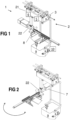
- the device 1 comprises an actuator 2, i.e. a locomotion system, for moving the device inside the animal housing facility, e.g. for moving the device along at least one spatial dimension preferably in an automatic way.
- the actuator 2 may adapted for slidably being mounted onto a rail system 3, such as an overhead rail, e.g. a ceiling-mounted rail.
- the actuator 2 may comprise a motor for propelling the movement of the device along the rail preferably in an automatic way.
- the actuator 2 comprises at least one wheel that, in use, is supported by the rail system 3 and a motor, e.g. in a motion box, to drive a rotation of at least one of the wheels, in a controlled manner, e.g.
- the device is not limited to devices that move along a ceiling-mounted track or rail, e.g. the device may be a track vehicle that moves along a ground-mounted track, a wall-mounted track, or an arbitrarily supported track or combination of tracks.
- Ground based devices are less preferred compared to hanging the device from a rail system. Ground based devices may optionally not be part of the present invention.
- the range of motion is not necessarily limited to a linear one-dimensional motion or a curvilinear path.
- the actuator may comprise means for switching tracks at track intersections or rail switches, preferably in an automatic way.
- the device may comprise a communication module 5 for receiving instructions and/or target (spatial) coordinates from a control system or a system for monitoring the welfare of livestock in a shed.
- the communication module can be part of an on-board controller.
- the control system may be adapted for receiving the inputs provided by one or more of the systems for monitoring the welfare of livestock, and may be adapted for providing outputs, such as (at least approximative) spatial coordinates of detected dead animals, to one or more of the devices 1 in accordance with embodiments of the present invention preferably automatically.
- the system for monitoring the welfare of the livestock may comprise a plurality of sensors for measuring ambient conditions in the shed and may comprise at least one camera. This system can be adapted for identifying and/or locating dead animals, e.g.
- the device may comprise, e.g. instead of or in addition to the communication module, a system for monitoring the welfare of livestock in a shed (further also referred to as "the monitoring system"), e.g. as described in the reference hereinabove, that is adapted for identifying and locating dead animals in the animal housing facility.
- the robot adapted to move through the shed and comprising at least two cameras, described in said document may be co-integrated in the device in accordance with embodiments of the present invention, or this robot may be separate entity (yet at least connected by means of a communication path), i.e. not moving through the shed using the same actuator 2 as referred to hereinabove.
- said robot and said actuator 2 may travel along the same system of rails through the animal housing facility.
- the robot and the actuator 2 may be modular and each may be mounted or mountable on a basic frame.
- the device comprises a processor 6 which can be part of one or more controllers or on-board controllers.
- the processor 6 is not necessarily limited to a general purpose processor (e.g. adapted for executing a program code), such as a central processing unit, a graphics processing unit, a cell processor, and the like, but may equally refer to an application-specific integrated circuit or configurable hardware, such as a field-programmable gate array.
- the processor 6 which can be part of one or more controllers or on-board controllers can be adapted for controlling (e.g. and operably connected to) the actuator 2, to move the actuator to a target position preferably automatically, e.g. to move a primary actuator 21 to an approximative position of the dead animal, e.g. as constrained by the degree(s) of freedom of the primary actuator, e.g. to a closest position to the dead animal on a track along which the primary actuator can move preferably automatically.
- the processor 6 which can be part of one or more controllers or on-board controllers, may be adapted for determining the target position by receiving and taking instructions and/or coordinates received by the communication unit 5 into account, and/or by taking a position of a dead animal as identified and located by the system monitoring the welfare of the livestock into account preferably automatically.
- the monitoring system may identify a dead animal and communicate the position of this dead animal to the processor 6 which can be part of one or more controllers or on-board controllers, in use of the device.
- the position may be determined by the monitoring system by taking at least its own position (e.g. position of said robot) into account when the dead animal is detected.
- the monitoring system merely comprises a robot that travels through the shed and identifies dead animals, e.g. using camera images.
- the processor 6 which can be part of the one or more controllers or one or more on-board controllers, may be alerted of the position of the robot when the dead animal was detected preferably automatically.
- the robot is adapted for refining the position of the dead animal by taking its own coordinates into account when detecting the dead animal as well as, for example, the camera images (e.g. stereovision images) and/or other sensor readings (such a range-finding laser, radar, lidar, and the like) into account preferably automatically.
- the processor 6 which can be part of one or more controllers or on-board controllers may receive a more precise position of the dead animal to act upon.
- the "more precise position” may define whether the dead chicken was detected on the left or on the right side of a track position where the robot is located (i.e. "more precise” may refer, in this example, to one bit of additional information, even though a plurality of additional bits of information may be even more preferred).
- the device (e.g. at least that part of the device that is mechanically connected to and/or integrated with the actuator 2) may be adapted for assuming a compact configuration when the processor 6 which can be part of one or more controllers or on-board controllers is waiting for a target position to be determined and/or while the actuator 2 is travelling through the shed toward a target position.
- the actuator 2 may comprise a primary actuator 21 for travelling through the shed to the target position, and at least one secondary actuator 22, such as an arm mechanism, for moving a manipulator 8, e.g. an end effector, e.g. a gripper, sufficiently close to the dead animal, once the target position is reached.
- the secondary actuator may be configured such that (e.g. retracted such that) the device assumes a small or minimal volume in space during a waiting phase and/or a travelling phase.
- FIG 1 may show an example of such a compact configuration.
- the device 1 comprises a camera 7 to assist in the identification and locating of the dead animal once the target position has been reached.
- the camera may be positioned on the manipulator of the secondary actuator 22, e.g. on the end effector of the arm mechanism.
- the secondary actuator 22 may be adapted for performing a scanning motion while the camera acquires images to identify and locate the dead animal preferably automatically.
- the scanning motion may comprise a rotation of the camera to capture images over an imaging arc.
- the processor which can be part of one or more controllers or on-board controllers may also have received, in operation, additional positional information of the dead animal, such as to limit the range of the scanning motion to a range where the dead animal is likely to be found. For example, based on an indication whether the dead animal is located on the left side or the right side with respect to a track position, the camera may be scanned over a first arc or a second arc, corresponding to respectively the left side or the right side of the track. This can be done automatically. Thus, a scanning sequence may be started to re-identify and locate the dead animal preferably automatically.
- the camera may perform a sweep, e.g. in the aforementioned example either right or left of the track along which the device moves through the shed, to locate the dead animal. This is preferably done automatically.
- the secondary actuator 22 e.g. the arm, may perform steps until the dead animal comes into view of the camera, at which time a more exact position of the dead animal can be determined (or is implicitly determined by the position at which the secondary actuator interrupts the scanning sweep). This preferably done automatically.
- the camera 7 may be the or a camera of the monitoring system, e.g. particularly (not necessarily exclusively) when the monitoring system is cointegrated (i.e. housed in or on an part actuated by the actuator) with the actuator 2.
- the camera may comprise at least two different cameras.
- a dead animal may be detected by a detected presence of an animal shape in an optical image (e.g. red-green-blue, RGB, image, or an equivalent and the absence of a heat signature of the animal in a thermal image (without necessarily being limited to this specific detection technique).
- the processor 6 which can be part of one or more controllers or on-board controllers can be adapted for controlling (e.g. and operably connected to) the actuator 2, to move the actuator to the target position preferably automatically.
- the processor which can be part of one or more controllers or on-board controllers can be adapted for, after moving to an approximative position of the dead animal, e.g. by controlling the primary actuator 21, steering the actuator 2, e.g. the secondary actuator 22, to a more precise position of the dead animal as located by the camera 7, e.g. by taking the more exact position of the dead animal as determined (e.g. by the processor) on the basis of the camera sweep into account. This is preferably done automatically.
- a manipulator 8 e.g.
- an end effector e.g. a gripper
- the position of the actuator e.g. of the secondary actuator 22
- the movement, performed in each iteration may comprise a translation in one or more dimensions and/or a rotation in one or more dimensions.
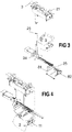
- the secondary actuator 22 comprises a telescopic arm 23 for vertically displacing the manipulator 8, e.g.
- the secondary actuator 22 comprises a rotation stage 24, e.g. at a free end of the telescopic arm and adapted for rotating a translation stage 25 in a horizontal plane.
- the translation stage is adapted for translating the manipulator 8 radially inward and outward preferably automatically, i.e. where 'radially' refers to the circular motion driven by the rotation stage 24.
- the position of the manipulator may be iteratively updated until it reaches a predetermined relative position with respect to the dead animal, e.g. a position above the dead animal.
- Control of this process may be provided by one or more controllers or on-board controllers.
- the one or more controllers or on-board controllers may perform the aforementioned comparison of optical images and thermal images which may be used to determine the relative position of the dead animal with respect to the manipulator in each iteration step, and to control the steering the manipulator closer, e.g. to the predetermined relative position preferably automatically.
- embodiments are not specifically limited to this approach for detecting the relative position of the dead animal.
- the processor 6 which may be part of one or more controllers or on-board controllers can be adapted to control the manipulator 8 such as to collect the dead animal with the manipulator preferably automatically. Aspects of the dead animal can be measured such as those which can give an indication of the health of the flock,
- the illustrative manipulator 8 shown in the drawings comprises a support surface 81 (support structure), e.g. generally shaped as a dustpan, onto which the dead animal can be placed.
- the support surface 81 can have e.g. a horizontal or substantially horizontal support surface.
- a displacement mechanism 82 can be provided such as a striking or shoving element for pushing the dead animal onto the support surface.
- the displacement mechanism may comprise a brush, a shovel, a rake or a similar structure.
- the manipulator 8 may be adapted for moving the displacement mechanism toward the support surface (or, equivalently, vice versa, or both elements toward each other) such that the dead animal, when positioned in between the displacement mechanism and the support surface can be shoved/moved onto the support surface by the movement of the displacement mechanism preferably automatically.
- a device in accordance with embodiments of the present invention may comprise different types of manipulator to collect the dead animal, such as a gripper, a tweezer, a hook, a robotic hand, a crotch to latch onto the neck, hocks or legs of the dead animal, a suction cup, or any other prior-art solution for grabbing, holding and/or supporting the dead animal.
- the device may comprise a receptacle 9, e.g. a basket, and the processor 6 which can be part of one or more controllers or on-board controllers may be adapted for depositing the dead animal into the receptacle, after the dead animal is collected by the manipulator 8 preferably automatically.
- the secondary actuator may be controlled to return to a default position e.g. a predetermined configuration. This default position may correspond to the compact configuration of the device as referred to hereinabove. In this default position, the manipulator may be positioned above the receptacle, see e.g. FIG 1 .
- the processor 6 which can be part of one or more controllers or on-board controllers may be adapted to open the manipulator 8 such as to release the dead animal into the receptacle, when the dead animal is collected by the manipulator and the default position has been reached preferably in an automatic manner.
- the receptacle may have an open end at the upper side, e.g. such that the dead animal can easily be dropped into the receptacle from above.
- the receptacle may be, at least roughly, shaped as a bucket, basket or hopper.
- the receptacle may comprise a container having an open upper side and is configured to be able to discharge its contents at the bottom, e.g. using an emptying mechanism. The container may taper downward.
- the receptacle preferably, is dimensioned such that it can store a plurality of dead animals, and the manipulator can be freed to collect a further dead animal while the basket already contains one or more dead animals.
- the device 1 may comprise a contents sensor 10, e.g. a load cell, to determine the weight, mass, volume or other quantity indicative of the dead animal(s) contained in the receptacle.
- a contents sensor does not necessarily measure the weight or volume of the contents of the receptacle directly, but may determine a weight or volume of the entire receptacle, a part of the device, or the entire device, assuming the mass or volume of the components of the device to be constant or substantially constant.
- a load cell way be integrated in the primary actuator to determine the total weight, from which the weight of the dead animals stored in the receptacle 9 can be determined in a straightforward manner.
- contents sensors may include a camera and suitable image analyzer to determine the contents of the receptacle 9, a radar or sonar apparatus or a laser rangefinder to determine the distance of an upper level of the contents in the receptacle to, for example, the upper rim of the receptacle, or an optical gate to determine when a reference level in the receptacle is obstructed by an item in the receptacle, without being limited by these examples.
- the processor 6 which can be part of one or more controllers or on-board controllers may be adapted to determine when the receptacle is full or substantially full preferably automatically, e.g. within a predetermined margin to avoid that a dead animal is added and falls out of the receptacle due to exceeding its capacity, based on a signal received from the contents sensor.
- the receptacle may be considered substantially full when a predetermined weight threshold, volume threshold, distance threshold and/or level indicator threshold is exceeded.
- the processor 6 which can be part of one or more controllers or on-board controllers may be adapted for determining relevant data regarding the (e.g. each) dead animal, e.g. body statistics and/or indicator(s) for determining a likely cause of death.
- the camera may be operated by the processor which can be part of one or more controllers or on-board controllers such as to obtain a (close-up) image of the dead animal when picked up by the manipulator 8.
- the processor which can be part of one or more controllers or onboard controllers may determine a weight of each dead animal, e.g. using the contents sensor 10, e.g. by difference of the total weight of the receptacle after and prior to adding a specific dead animal.
- the device may comprise one or more sensors to determine one or more properties of the dead animal when picked up by the manipulator.
- the processor 6 which can be part of one or more controllers or on-board controllers may be adapted to store in a memory or transmit using the communication unit the body statistics and/or indicator(s) for each collected dead animal.
- the processor 6 which can be part of one or more controllers or on-board controllers may be adapted for controlling the actuator 2, to move the actuator to a predetermined disposal location, e.g. to move the primary actuator 21 to a predetermined disposal location, when the receptacle is determined to be full or substantially full. While the device is traveling to the disposal location, the device (e.g. at least that part of the device that is mechanically connected to and/or integrated with the actuator 2) may be adapted for assuming the compact configuration.
- the processor 6 which can be part of one or more controllers or onboard controllers may be adapted to control an emptying mechanism 11 of the receptacle 9 preferably automatically, such as to empty the receptacle when the disposal location has been reached, e.g. when the device is at the disposal location.
- the emptying mechanism 11 may comprise a piston to move two parts, e.g. halves, of the receptacle forming a hopper structure.
- the present invention relates to a method for removing animal carcasses, such as poultry carcasses, from an animal housing facility.
- FIG 5 an illustrative method 100 in accordance with embodiments of the second aspect of the present invention is shown.
- the method 100 may comprise determining in step 111, e.g. using a processor 6 which can be part of one or more controllers or on-board controllers, a target position for collecting a dead animal, in which this target position is determined by taking or receiving instructions and/or coordinates received via a communication unit 5 and/or by taking a position of a dead animal as identified and located by a monitoring system into account.
- the monitoring system may be a system for monitoring the welfare of animals in the animal housing facility and for identifying and locating dead animals in the animal housing facility.
- the method 100 comprises moving in step 101 a manipulator 8 inside the animal housing facility, e.g. under the control of the processor 6, which can be part of one or more controllers or on-board controllers to a target position indicative of a rough position of a dead animal in the animal housing facility.
- a manipulator 8 inside the animal housing facility, e.g. under the control of the processor 6, which can be part of one or more controllers or on-board controllers to a target position indicative of a rough position of a dead animal in the animal housing facility.
- the method can comprise identifying and locating in step 102 the dead animal using a camera 7, when the target position is reached, e.g. by processing images acquired by the camera using the processor which can be part of one or more controllers or on-board controllers.
- the camera 7 may be attached to the manipulator 8, e.g. in a fixed arrangement with respect to an actuatable end of the manipulator.
- the identifying and locating the dead animal in step 102 may comprise performing a sweeping motion in step 112 (e.g. under control of the processor which can be part of one or more controllers or on-board controllers) to move the camera over an imaging sweep range until the dead animal is recognized, e.g. by the processor which can be part of one or more controllers or on-board controllers, in an image acquired by the camera.
- an optical image e.g. an RGB image
- a thermal image e.g. acquired by the thermal camera.
- Performing the sweeping (scanning; tracking) motion in step 112 may comprise selecting the imaging sweep range, e.g. by the processor which can be part of one or more controllers or on-board controllers, from a plurality of possible imaging sweep ranges taking the target position into account, such as to limit the range of the scanning motion to a range where the dead animal is likely to be found.
- the target position as determined in step 111 may comprise more information, e.g. be more accurate, than can be accounted for in the step 111 of moving the manipulator, and this additional information may be used to select a imaging sweep range, e.g. volume of interest, where the camera searches for the dead animal.
- the step of moving 101 may be constrained by physical limitations, such as the freedom of movement allowed by traveling along a rail or track system 3.
- the method can comprise steering in step 103 the manipulator 8 to a precise position of the dead animal as located by using the camera 7, e.g. steering the manipulator by the processor which can be part of one or more controllers or on-board controllers, such that the manipulator 8 is brought into a predetermined relative position with respect to the dead animal.
- the processor which can be part of one or more controllers or on-board controllers, such that the manipulator 8 is brought into a predetermined relative position with respect to the dead animal.
- the steering in step 103 of the manipulator may comprise iteratively determining a next movement in a next iteration step taking sensor data and/or a camera image acquired in a present iteration step into account, thus iteratively updating in step 113 the position of the manipulator until the manipulator reaches the predetermined relative position with respect to the dead animal.
- the manipulator 8 may be mounted on a secondary actuator 22, which is controlled in the step 103 of steering the manipulator.
- This secondary actuator 22 may be mounted on a primary actuator 21 for moving 101,105 the assembly in the animal housing facility.
- the primary actuator may provide mobility of the assembly over a relatively long distance, e.g. a range of at least 5m, e.g. a range of at least 10m, e.g. a range of at least 50m, e.g. a range of at least 100m.
- the primary actuator 21 may be mounted in a rail system 3, and, thus, the steps of moving 101,105 may comprise moving a track or rail of the rail system 3.
- the secondary actuator 22 may provide (more) precise control on the position of the manipulator, e.g.
- the secondary actuator may provide more degrees of freedom, e.g. at least two independent components of translation and/or rotation, e.g. at least three independent components of translation and/or rotation, e.g. at least four independent components of translation and/or rotation.
- steering 103 the manipulator 8 may comprise steering the secondary actuator 22 to the more precise position of the dead animal as determined by the processor which can be part of one or more controllers or on-board controllers, using the camera.
- the secondary actuator 22 may comprise a telescopic arm 23 for vertically displacing the manipulator 8, a rotation stage 24 on the telescopic arm, and a translation stage 25 on the rotation stage.
- the rotation stage is adapted for rotating the translation stage in a horizontal plane and the translation stage is adapted for translating the manipulator 8 radially inward and outward.
- the method comprises collecting in step 104 the dead animal with the manipulator 8, e.g. under the control of the processor 6 which can be part of one or more controllers or onboard controllers, when the manipulator is in the predetermined relative position, e.g. (straight) above the dead animal. Aspects of the dead animal can be measured such as those which can give an indication of the health of the flock.
- the manipulator 8 may comprise a support surface 81 onto which the dead animal can be placed, and a displacement mechanism 82 for pushing the dead animal onto the support surface when controlled by the processor 6 which can be part of one or more controllers or on-board controllers, so as to collect the dead animal.
- collecting the dead animal in step 104 may comprise lowering the manipulator in an open position from above the dead animal, such that the dead animal is positioned in between a support surface and a displacement mechanism, and then closing the manipulator such that the support surface and the displacement mechanism are moved toward each other, thereby pushing the dead animal onto the support surface.
- the method may comprise depositing in step 114 the dead animal collected by the manipulator 8 into a receptacle 9.
- the receptacle may be attached to a frame such that it moves along with the manipulator in the step 101 of moving the manipulator 8 inside the animal housing facility and in the step 105 of moving the manipulator to the predetermined disposal location.
- the manipulator 8 may be adapted for moving (e.g. substantially) independently of the receptacle 9 in the steps 103 of steering the manipulator 8 to the precise position of the dead animal and collecting in step 104 the dead animal with the manipulator 8. Aspects of the dead animal can be measured such as those which can give an indication of the health of the flock,
- the step 114 of depositing may comprise controlling, by the processor which can be part of one or more controllers or on-board controllers, the manipulator so as to deposit the dead animal into the receptacle 9.
- step 114 of depositing the dead animal may comprise positioning the manipulator 8 above an open end at an upper side of the receptacle 9 and controlling the manipulator 8 such as to release the collected dead animal when positioned above the open upper side of the receptacle.
- the method may comprise determining in step 115, e.g. by the processor 6 which can be part of one or more controllers or on-board controllers, when said receptacle is full or substantially full.
- this determining step 115 may comprise determining a quantity indicative of the contents of the receptacle, e.g. using a contents sensor 10. This quantity may comprise a weight, a mass, a volume, a distance from a reference point to a nearest point occupied by contents of the receptacle along a sensing path, an interruption of a line of sight along an optical gate path in the receptacle, and the like.
- step 115 when determining when the receptacle is full or substantially full may thus be based on a signal received from the contents sensor.
- the method comprises moving in step 105, e.g. under control of the processor, the manipulator to a predetermined disposal location and depositing step 106, e.g. under control of the processor which can be part of one or more controllers or on-board controllers, the dead animal at the disposal location.
- step 105 for moving the manipulator to the predetermined disposal location, may comprise moving step 116 for moving the receptacle (which, as mentioned hereinabove, may move along with the manipulator in the step of moving step 105 the manipulator) to the predetermined disposal location when the receptacle is determined to be full or substantially full.
- moving step 116 for moving the receptacle (which, as mentioned hereinabove, may move along with the manipulator in the step of moving step 105 the manipulator) to the predetermined disposal location when the receptacle is determined to be full or substantially full.
- the method may comprise repeating in step 118 the steps 101, 102, 103, 104, 114 and 115, and optionally also the steps 111 and/or 112 and/or 113, when the receptacle is determined to be not (yet) full or substantially full.
- Depositing the dead animal in step 106 may comprise discharging in step 117 the contents of the receptacle at the disposal location, e.g. under the control of the processor 6 which can be part of one or more controllers or on-board controllers and using an emptying mechanism of the receptacle.
- the processor 6 which can be part of one or more controllers or on-board controllers and using an emptying mechanism of the receptacle.
- the present invention relates to a computer program product for, when executed by a processor, performing a method in accordance with embodiments of the second aspect of the present invention.
- software may be implemented as a computer program product which has been compiled for a processing engine like processor 6 to carry out any of the methods of the present invention or is compiled to execute in an interpretative virtual machine such as the Java TM Virtual Machine running on processor 6.
- a number or all of software components can be stored in the memory and are executable by the processor 6, e.g. the processor 6 can a component in a controller such as an on-board controller.
- executable means a program file that is in a form that can ultimately be run by the processor 6.
- executable programs may be, for example, a compiled program that can be translated into machine code in a format that can be loaded into a random access memory and run by the processor 6, or source code that may be expressed in proper format such as object code that is capable of being loaded into a random access memory and executed by the processor 6, or source code that may be interpreted by another executable program to generate instructions in a random access memory to be executed by the processor 6, etc.
- a device according to embodiments of the present invention may comprise logic encoded in media for performing any step, or steps of the methods according to embodiments of the present invention.
- Logic may comprise software encoded in a disk or other computer-readable medium and/or instructions encoded in an application specific integrated circuit (ASIC), field programmable gate array (FPGA), or other processor or hardware.
- a device will also include a CPU and/a GPU and memory, the CPU and/or GPU having a processing engine able to execute software of the present invention.
- the software can be embodied in a computer program product adapted to carry out the following functions when the software is loaded onto the respective device or devices and executed on one or more processing engines such as microprocessors, ASICs, FPGAs etc.:
- the software can be embodied in a computer program product adapted to carry out the following functions when the software is loaded onto the respective device or devices and executed on one or more processing engines such as microprocessors, ASICs, FPGAs etc.:
- the software can be embodied in a computer program product adapted to carry out the following functions when the software is loaded onto the respective device or devices and executed on one or more processing engines such as microprocessors, ASICs, FPGAs etc.:
- the software can be embodied in a computer program product adapted to carry out the following functions when the software is loaded onto the respective device or devices and executed on one or more processing engines such as microprocessors, ASICs, FPGAs etc.:
- the software e.g. in the form of a computer product mentioned above can be stored on a non-transitory signal storage medium, such as an optical disk (CD-ROM or DVD-ROM); a magnetic tape, a magnetic disk, a ROM, or a solid state memory such as a USB flash memory or similar.
- a non-transitory signal storage medium such as an optical disk (CD-ROM or DVD-ROM); a magnetic tape, a magnetic disk, a ROM, or a solid state memory such as a USB flash memory or similar.
Landscapes
- Engineering & Computer Science (AREA)
- Life Sciences & Earth Sciences (AREA)
- Environmental Sciences (AREA)
- Robotics (AREA)
- Mechanical Engineering (AREA)
- Biodiversity & Conservation Biology (AREA)
- Animal Husbandry (AREA)
- Biophysics (AREA)
- Birds (AREA)
- Catching Or Destruction (AREA)
- Cleaning In General (AREA)
- Manipulator (AREA)
- Housing For Livestock And Birds (AREA)
Priority Applications (11)
| Application Number | Priority Date | Filing Date | Title |
|---|---|---|---|
| DK20155022.5T DK3858142T3 (da) | 2020-01-31 | 2020-01-31 | Automatiseret fjernelse af døde dyrekroppe |
| ES20155022T ES2942158T3 (es) | 2020-01-31 | 2020-01-31 | Eliminación automática de cadáveres de animales |
| PL20155022.5T PL3858142T3 (pl) | 2020-01-31 | 2020-01-31 | Zautomatyzowane usuwanie zwłok zwierzęcych |
| EP20155022.5A EP3858142B1 (en) | 2020-01-31 | 2020-01-31 | Automated removal of animal carcasses |
| US17/759,548 US20230052580A1 (en) | 2020-01-31 | 2021-01-25 | Automated removal of animal carcasses |
| MX2022009271A MX2022009271A (es) | 2020-01-31 | 2021-01-25 | Remoción automatizada de canales de animales. |
| PCT/EP2021/051612 WO2021151834A1 (en) | 2020-01-31 | 2021-01-25 | Automated removal of animal carcasses |
| BR112022014847A BR112022014847A2 (pt) | 2020-01-31 | 2021-01-25 | Remoção automatizada de carcaças de animais |
| EP21705434.5A EP4096410A1 (en) | 2020-01-31 | 2021-01-25 | Automated removal of animal carcasses |
| CN202180019730.4A CN115379761B (zh) | 2020-01-31 | 2021-01-25 | 动物尸体的自动化移除 |
| CA3168698A CA3168698A1 (en) | 2020-01-31 | 2021-01-25 | Automated removal of animal carcasses |
Applications Claiming Priority (1)
| Application Number | Priority Date | Filing Date | Title |
|---|---|---|---|
| EP20155022.5A EP3858142B1 (en) | 2020-01-31 | 2020-01-31 | Automated removal of animal carcasses |
Publications (2)
| Publication Number | Publication Date |
|---|---|
| EP3858142A1 EP3858142A1 (en) | 2021-08-04 |
| EP3858142B1 true EP3858142B1 (en) | 2023-03-29 |
Family
ID=69467334
Family Applications (2)
| Application Number | Title | Priority Date | Filing Date |
|---|---|---|---|
| EP20155022.5A Active EP3858142B1 (en) | 2020-01-31 | 2020-01-31 | Automated removal of animal carcasses |
| EP21705434.5A Withdrawn EP4096410A1 (en) | 2020-01-31 | 2021-01-25 | Automated removal of animal carcasses |
Family Applications After (1)
| Application Number | Title | Priority Date | Filing Date |
|---|---|---|---|
| EP21705434.5A Withdrawn EP4096410A1 (en) | 2020-01-31 | 2021-01-25 | Automated removal of animal carcasses |
Country Status (10)
| Country | Link |
|---|---|
| US (1) | US20230052580A1 (es) |
| EP (2) | EP3858142B1 (es) |
| CN (1) | CN115379761B (es) |
| BR (1) | BR112022014847A2 (es) |
| CA (1) | CA3168698A1 (es) |
| DK (1) | DK3858142T3 (es) |
| ES (1) | ES2942158T3 (es) |
| MX (1) | MX2022009271A (es) |
| PL (1) | PL3858142T3 (es) |
| WO (1) | WO2021151834A1 (es) |
Families Citing this family (6)
| Publication number | Priority date | Publication date | Assignee | Title |
|---|---|---|---|---|
| CN113854197A (zh) * | 2021-11-04 | 2021-12-31 | 河北农业大学 | 一种鸡舍底层笼内死鸡捡拾夹持器 |
| CN113907030B (zh) * | 2021-11-05 | 2022-11-08 | 朱志国 | 一种水产养殖用投食装置 |
| CN114407051A (zh) * | 2022-03-07 | 2022-04-29 | 烟台艾睿光电科技有限公司 | 畜禽养殖场巡检方法及畜禽养殖场机器人 |
| CN114800548B (zh) * | 2022-03-30 | 2023-11-14 | 中国农业大学 | 畜禽舍用抓取装置 |
| WO2024176008A1 (en) | 2023-02-23 | 2024-08-29 | Farm Robotics And Automation Sl | Aviary monitoring devices and related systems |
| WO2024176007A1 (en) | 2023-02-23 | 2024-08-29 | Farm Robotics And Automation Sl | Aviary monitoring system and related methods |
Family Cites Families (23)
| Publication number | Priority date | Publication date | Assignee | Title |
|---|---|---|---|---|
| US4020793A (en) | 1975-12-29 | 1977-05-03 | B & J Machinery Co., Inc. | Apparatus and method for raising and transporting poultry |
| US4223638A (en) | 1979-01-24 | 1980-09-23 | Sappington Marr D | Apparatus for feeding poultry |
| US4292928A (en) * | 1979-11-19 | 1981-10-06 | Kopylov Alexei A | Poultry brooding plant |
| DE3124635C2 (de) * | 1981-06-23 | 1986-08-28 | Hergeth Hollingsworth GmbH, 4408 Dülmen | Vorrichtung zum Abarbeiten von Faserballen, insbesondere Preßballen aus Baumwolle |
| NL9002465A (nl) * | 1990-11-12 | 1992-06-01 | Nedap Nv | Voersysteem voor dieren. |
| US6779486B2 (en) * | 2001-10-17 | 2004-08-24 | Feedlogic Systems Inc. | Automatic animal feeder |
| US6810832B2 (en) * | 2002-09-18 | 2004-11-02 | Kairos, L.L.C. | Automated animal house |
| US20040245073A1 (en) | 2003-06-09 | 2004-12-09 | Hawk John M. | System and method for removing dead animals |
| US6939218B1 (en) | 2004-01-27 | 2005-09-06 | William C. Holland | Method and apparatus of removing dead poultry from a poultry house |
| NL1033589C2 (nl) * | 2007-03-26 | 2008-09-29 | Maasland Nv | Samenstel van een melkrobot met een melkrobotvoerplaats, en inrichting voor het grijpen en verplaatsen van materiaal. |
| NL2008673C2 (nl) * | 2012-04-20 | 2013-10-23 | Lely Patent Nv | Inrichting voor het verplaatsen van voer. |
| US8820264B2 (en) * | 2012-06-07 | 2014-09-02 | Scott Trantina | Remotely controlled feeding station |
| KR20140102824A (ko) * | 2013-02-15 | 2014-08-25 | 김용진 | 애완견용 배변 훈련기 |
| CN104621004B (zh) * | 2014-12-22 | 2017-01-25 | 中国农业大学 | 一种生物及环境监测智能机器人 |
| US11019805B2 (en) * | 2016-07-20 | 2021-06-01 | Farm Robotics And Automation Sl | Robot assisted surveillance of livestock |
| US10820574B2 (en) * | 2016-07-29 | 2020-11-03 | International Business Machines Corporation | Specialized contextual drones for virtual fences |
| CN208191844U (zh) * | 2018-02-07 | 2018-12-07 | 徐云生 | 禽类养殖机器人以及禽类养殖场 |
| CN207984675U (zh) * | 2018-03-20 | 2018-10-19 | 湖南祥柏工业油脂有限公司 | 一种自动化病死动物尸体无害化收集车 |
| CN208744811U (zh) * | 2018-07-19 | 2019-04-16 | 天津中新智通科技有限公司 | 一种方便安装的智能分拣机械手 |
| FR3088169B1 (fr) * | 2018-11-13 | 2021-06-18 | Dussau Distrib | Ensemble de surveillance et d'intervention pour locaux d'elevage |
| CN209806804U (zh) * | 2019-03-28 | 2019-12-20 | 华中农业大学 | 一种畜禽养殖场多功能移动平台 |
| CN110612922B (zh) * | 2019-09-12 | 2022-04-12 | 徐云生 | 一种畜牧自动养殖系统 |
| EP3859289A1 (en) * | 2020-01-31 | 2021-08-04 | Farm Robotics and Automation SL | Weighing of animals |
-
2020
- 2020-01-31 EP EP20155022.5A patent/EP3858142B1/en active Active
- 2020-01-31 ES ES20155022T patent/ES2942158T3/es active Active
- 2020-01-31 DK DK20155022.5T patent/DK3858142T3/da active
- 2020-01-31 PL PL20155022.5T patent/PL3858142T3/pl unknown
-
2021
- 2021-01-25 CN CN202180019730.4A patent/CN115379761B/zh active Active
- 2021-01-25 MX MX2022009271A patent/MX2022009271A/es unknown
- 2021-01-25 US US17/759,548 patent/US20230052580A1/en active Pending
- 2021-01-25 CA CA3168698A patent/CA3168698A1/en active Pending
- 2021-01-25 WO PCT/EP2021/051612 patent/WO2021151834A1/en active Application Filing
- 2021-01-25 EP EP21705434.5A patent/EP4096410A1/en not_active Withdrawn
- 2021-01-25 BR BR112022014847A patent/BR112022014847A2/pt unknown
Also Published As
| Publication number | Publication date |
|---|---|
| BR112022014847A2 (pt) | 2022-09-27 |
| MX2022009271A (es) | 2022-10-27 |
| ES2942158T3 (es) | 2023-05-30 |
| US20230052580A1 (en) | 2023-02-16 |
| EP3858142A1 (en) | 2021-08-04 |
| CN115379761B (zh) | 2024-04-30 |
| CA3168698A1 (en) | 2021-08-05 |
| EP4096410A1 (en) | 2022-12-07 |
| DK3858142T3 (da) | 2023-06-12 |
| WO2021151834A1 (en) | 2021-08-05 |
| PL3858142T3 (pl) | 2023-07-24 |
| CN115379761A (zh) | 2022-11-22 |
Similar Documents
| Publication | Publication Date | Title |
|---|---|---|
| EP3858142B1 (en) | Automated removal of animal carcasses | |
| US11019805B2 (en) | Robot assisted surveillance of livestock | |
| US10327415B2 (en) | System and method for improved attachment of a cup to a dairy animal | |
| US9271471B2 (en) | System and method for analyzing data captured by a three-dimensional camera | |
| US9058657B2 (en) | System and method for filtering data captured by a 3D camera | |
| WO2022207766A1 (en) | Egg collection system comprising an autonomous robot for retrieving eggs and method of collecting eggs | |
| US10303939B2 (en) | System and method for filtering data captured by a 2D camera | |
| US20090164234A1 (en) | Livestock tracking system and method | |
| US9171208B2 (en) | System and method for filtering data captured by a 2D camera | |
| EP4097428B1 (en) | Weighing of animals | |
| US9681634B2 (en) | System and method to determine a teat position using edge detection in rear images of a livestock from two cameras | |
| US12016310B2 (en) | System and method for identifying and recovering expired poultry | |
| RU2780844C1 (ru) | Беспилотная самоходная система для сбора яиц при напольном содержании птицы |
Legal Events
| Date | Code | Title | Description |
|---|---|---|---|
| PUAI | Public reference made under article 153(3) epc to a published international application that has entered the european phase |
Free format text: ORIGINAL CODE: 0009012 |
|
| STAA | Information on the status of an ep patent application or granted ep patent |
Free format text: STATUS: THE APPLICATION HAS BEEN PUBLISHED |
|
| AK | Designated contracting states |
Kind code of ref document: A1 Designated state(s): AL AT BE BG CH CY CZ DE DK EE ES FI FR GB GR HR HU IE IS IT LI LT LU LV MC MK MT NL NO PL PT RO RS SE SI SK SM TR |
|
| STAA | Information on the status of an ep patent application or granted ep patent |
Free format text: STATUS: REQUEST FOR EXAMINATION WAS MADE |
|
| 17P | Request for examination filed |
Effective date: 20220204 |
|
| RBV | Designated contracting states (corrected) |
Designated state(s): AL AT BE BG CH CY CZ DE DK EE ES FI FR GB GR HR HU IE IS IT LI LT LU LV MC MK MT NL NO PL PT RO RS SE SI SK SM TR |
|
| GRAP | Despatch of communication of intention to grant a patent |
Free format text: ORIGINAL CODE: EPIDOSNIGR1 |
|
| STAA | Information on the status of an ep patent application or granted ep patent |
Free format text: STATUS: GRANT OF PATENT IS INTENDED |
|
| INTG | Intention to grant announced |
Effective date: 20221125 |
|
| GRAS | Grant fee paid |
Free format text: ORIGINAL CODE: EPIDOSNIGR3 |
|
| GRAA | (expected) grant |
Free format text: ORIGINAL CODE: 0009210 |
|
| STAA | Information on the status of an ep patent application or granted ep patent |
Free format text: STATUS: THE PATENT HAS BEEN GRANTED |
|
| AK | Designated contracting states |
Kind code of ref document: B1 Designated state(s): AL AT BE BG CH CY CZ DE DK EE ES FI FR GB GR HR HU IE IS IT LI LT LU LV MC MK MT NL NO PL PT RO RS SE SI SK SM TR |
|
| REG | Reference to a national code |
Ref country code: CH Ref legal event code: EP |
|
| REG | Reference to a national code |
Ref country code: NL Ref legal event code: FP |
|
| REG | Reference to a national code |
Ref country code: DE Ref legal event code: R096 Ref document number: 602020009123 Country of ref document: DE |
|
| REG | Reference to a national code |
Ref country code: AT Ref legal event code: REF Ref document number: 1556061 Country of ref document: AT Kind code of ref document: T Effective date: 20230415 |
|
| REG | Reference to a national code |
Ref country code: IE Ref legal event code: FG4D |
|
| REG | Reference to a national code |
Ref country code: ES Ref legal event code: FG2A Ref document number: 2942158 Country of ref document: ES Kind code of ref document: T3 Effective date: 20230530 |
|
| REG | Reference to a national code |
Ref country code: DK Ref legal event code: T3 Effective date: 20230609 |
|
| P01 | Opt-out of the competence of the unified patent court (upc) registered |
Effective date: 20230518 |
|
| REG | Reference to a national code |
Ref country code: LT Ref legal event code: MG9D |
|
| PG25 | Lapsed in a contracting state [announced via postgrant information from national office to epo] |
Ref country code: RS Free format text: LAPSE BECAUSE OF FAILURE TO SUBMIT A TRANSLATION OF THE DESCRIPTION OR TO PAY THE FEE WITHIN THE PRESCRIBED TIME-LIMIT Effective date: 20230329 Ref country code: NO Free format text: LAPSE BECAUSE OF FAILURE TO SUBMIT A TRANSLATION OF THE DESCRIPTION OR TO PAY THE FEE WITHIN THE PRESCRIBED TIME-LIMIT Effective date: 20230629 Ref country code: LV Free format text: LAPSE BECAUSE OF FAILURE TO SUBMIT A TRANSLATION OF THE DESCRIPTION OR TO PAY THE FEE WITHIN THE PRESCRIBED TIME-LIMIT Effective date: 20230329 Ref country code: LT Free format text: LAPSE BECAUSE OF FAILURE TO SUBMIT A TRANSLATION OF THE DESCRIPTION OR TO PAY THE FEE WITHIN THE PRESCRIBED TIME-LIMIT Effective date: 20230329 Ref country code: HR Free format text: LAPSE BECAUSE OF FAILURE TO SUBMIT A TRANSLATION OF THE DESCRIPTION OR TO PAY THE FEE WITHIN THE PRESCRIBED TIME-LIMIT Effective date: 20230329 |
|
| REG | Reference to a national code |
Ref country code: AT Ref legal event code: MK05 Ref document number: 1556061 Country of ref document: AT Kind code of ref document: T Effective date: 20230329 |
|
| PG25 | Lapsed in a contracting state [announced via postgrant information from national office to epo] |
Ref country code: SE Free format text: LAPSE BECAUSE OF FAILURE TO SUBMIT A TRANSLATION OF THE DESCRIPTION OR TO PAY THE FEE WITHIN THE PRESCRIBED TIME-LIMIT Effective date: 20230329 Ref country code: GR Free format text: LAPSE BECAUSE OF FAILURE TO SUBMIT A TRANSLATION OF THE DESCRIPTION OR TO PAY THE FEE WITHIN THE PRESCRIBED TIME-LIMIT Effective date: 20230630 Ref country code: FI Free format text: LAPSE BECAUSE OF FAILURE TO SUBMIT A TRANSLATION OF THE DESCRIPTION OR TO PAY THE FEE WITHIN THE PRESCRIBED TIME-LIMIT Effective date: 20230329 |
|
| PG25 | Lapsed in a contracting state [announced via postgrant information from national office to epo] |
Ref country code: SM Free format text: LAPSE BECAUSE OF FAILURE TO SUBMIT A TRANSLATION OF THE DESCRIPTION OR TO PAY THE FEE WITHIN THE PRESCRIBED TIME-LIMIT Effective date: 20230329 Ref country code: PT Free format text: LAPSE BECAUSE OF FAILURE TO SUBMIT A TRANSLATION OF THE DESCRIPTION OR TO PAY THE FEE WITHIN THE PRESCRIBED TIME-LIMIT Effective date: 20230731 Ref country code: EE Free format text: LAPSE BECAUSE OF FAILURE TO SUBMIT A TRANSLATION OF THE DESCRIPTION OR TO PAY THE FEE WITHIN THE PRESCRIBED TIME-LIMIT Effective date: 20230329 Ref country code: AT Free format text: LAPSE BECAUSE OF FAILURE TO SUBMIT A TRANSLATION OF THE DESCRIPTION OR TO PAY THE FEE WITHIN THE PRESCRIBED TIME-LIMIT Effective date: 20230329 |
|
| PG25 | Lapsed in a contracting state [announced via postgrant information from national office to epo] |
Ref country code: SK Free format text: LAPSE BECAUSE OF FAILURE TO SUBMIT A TRANSLATION OF THE DESCRIPTION OR TO PAY THE FEE WITHIN THE PRESCRIBED TIME-LIMIT Effective date: 20230329 Ref country code: IS Free format text: LAPSE BECAUSE OF FAILURE TO SUBMIT A TRANSLATION OF THE DESCRIPTION OR TO PAY THE FEE WITHIN THE PRESCRIBED TIME-LIMIT Effective date: 20230729 |
|
| REG | Reference to a national code |
Ref country code: DE Ref legal event code: R097 Ref document number: 602020009123 Country of ref document: DE |
|
| PG25 | Lapsed in a contracting state [announced via postgrant information from national office to epo] |
Ref country code: CZ Free format text: LAPSE BECAUSE OF FAILURE TO SUBMIT A TRANSLATION OF THE DESCRIPTION OR TO PAY THE FEE WITHIN THE PRESCRIBED TIME-LIMIT Effective date: 20230329 |
|
| PLBE | No opposition filed within time limit |
Free format text: ORIGINAL CODE: 0009261 |
|
| STAA | Information on the status of an ep patent application or granted ep patent |
Free format text: STATUS: NO OPPOSITION FILED WITHIN TIME LIMIT |
|
| PGFP | Annual fee paid to national office [announced via postgrant information from national office to epo] |
Ref country code: NL Payment date: 20240119 Year of fee payment: 5 |
|
| 26N | No opposition filed |
Effective date: 20240103 |
|
| PGFP | Annual fee paid to national office [announced via postgrant information from national office to epo] |
Ref country code: ES Payment date: 20240228 Year of fee payment: 5 |
|
| PGFP | Annual fee paid to national office [announced via postgrant information from national office to epo] |
Ref country code: RO Payment date: 20240123 Year of fee payment: 5 Ref country code: DE Payment date: 20240119 Year of fee payment: 5 Ref country code: GB Payment date: 20240123 Year of fee payment: 5 |
|
| PG25 | Lapsed in a contracting state [announced via postgrant information from national office to epo] |
Ref country code: SI Free format text: LAPSE BECAUSE OF FAILURE TO SUBMIT A TRANSLATION OF THE DESCRIPTION OR TO PAY THE FEE WITHIN THE PRESCRIBED TIME-LIMIT Effective date: 20230329 |
|
| PG25 | Lapsed in a contracting state [announced via postgrant information from national office to epo] |
Ref country code: SI Free format text: LAPSE BECAUSE OF FAILURE TO SUBMIT A TRANSLATION OF THE DESCRIPTION OR TO PAY THE FEE WITHIN THE PRESCRIBED TIME-LIMIT Effective date: 20230329 |
|
| PGFP | Annual fee paid to national office [announced via postgrant information from national office to epo] |
Ref country code: PL Payment date: 20240118 Year of fee payment: 5 Ref country code: IT Payment date: 20240122 Year of fee payment: 5 Ref country code: FR Payment date: 20240122 Year of fee payment: 5 Ref country code: DK Payment date: 20240124 Year of fee payment: 5 |
|
| PG25 | Lapsed in a contracting state [announced via postgrant information from national office to epo] |
Ref country code: MC Free format text: LAPSE BECAUSE OF FAILURE TO SUBMIT A TRANSLATION OF THE DESCRIPTION OR TO PAY THE FEE WITHIN THE PRESCRIBED TIME-LIMIT Effective date: 20230329 |
|
| PG25 | Lapsed in a contracting state [announced via postgrant information from national office to epo] |
Ref country code: MC Free format text: LAPSE BECAUSE OF FAILURE TO SUBMIT A TRANSLATION OF THE DESCRIPTION OR TO PAY THE FEE WITHIN THE PRESCRIBED TIME-LIMIT Effective date: 20230329 |
|
| REG | Reference to a national code |
Ref country code: CH Ref legal event code: PL |
|
| PG25 | Lapsed in a contracting state [announced via postgrant information from national office to epo] |
Ref country code: LU Free format text: LAPSE BECAUSE OF NON-PAYMENT OF DUE FEES Effective date: 20240131 |