EP3856552B1 - Gebläse für eine heizungs-, -lüftungs- und/oder -klimatisierungsvorrichtung eines kraftfahrzeugs - Google Patents
Gebläse für eine heizungs-, -lüftungs- und/oder -klimatisierungsvorrichtung eines kraftfahrzeugs Download PDFInfo
- Publication number
- EP3856552B1 EP3856552B1 EP19790637.3A EP19790637A EP3856552B1 EP 3856552 B1 EP3856552 B1 EP 3856552B1 EP 19790637 A EP19790637 A EP 19790637A EP 3856552 B1 EP3856552 B1 EP 3856552B1
- Authority
- EP
- European Patent Office
- Prior art keywords
- air
- blower
- air inlet
- turbine
- axis
- Prior art date
- Legal status (The legal status is an assumption and is not a legal conclusion. Google has not performed a legal analysis and makes no representation as to the accuracy of the status listed.)
- Active
Links
Images


Classifications
-
- B—PERFORMING OPERATIONS; TRANSPORTING
- B60—VEHICLES IN GENERAL
- B60H—ARRANGEMENTS OF HEATING, COOLING, VENTILATING OR OTHER AIR-TREATING DEVICES SPECIALLY ADAPTED FOR PASSENGER OR GOODS SPACES OF VEHICLES
- B60H1/00—Heating, cooling or ventilating devices
- B60H1/00007—Combined heating, ventilating, or cooling devices
- B60H1/00021—Air flow details of HVAC devices
-
- B—PERFORMING OPERATIONS; TRANSPORTING
- B60—VEHICLES IN GENERAL
- B60H—ARRANGEMENTS OF HEATING, COOLING, VENTILATING OR OTHER AIR-TREATING DEVICES SPECIALLY ADAPTED FOR PASSENGER OR GOODS SPACES OF VEHICLES
- B60H1/00—Heating, cooling or ventilating devices
- B60H1/00457—Ventilation unit, e.g. combined with a radiator
- B60H1/00471—The ventilator being of the radial type, i.e. with radial expulsion of the air
-
- B—PERFORMING OPERATIONS; TRANSPORTING
- B60—VEHICLES IN GENERAL
- B60H—ARRANGEMENTS OF HEATING, COOLING, VENTILATING OR OTHER AIR-TREATING DEVICES SPECIALLY ADAPTED FOR PASSENGER OR GOODS SPACES OF VEHICLES
- B60H1/00—Heating, cooling or ventilating devices
- B60H1/00642—Control systems or circuits; Control members or indication devices for heating, cooling or ventilating devices
- B60H1/00664—Construction or arrangement of damper doors
-
- F—MECHANICAL ENGINEERING; LIGHTING; HEATING; WEAPONS; BLASTING
- F04—POSITIVE - DISPLACEMENT MACHINES FOR LIQUIDS; PUMPS FOR LIQUIDS OR ELASTIC FLUIDS
- F04D—NON-POSITIVE-DISPLACEMENT PUMPS
- F04D29/00—Details, component parts, or accessories
- F04D29/26—Rotors specially for elastic fluids
- F04D29/28—Rotors specially for elastic fluids for centrifugal or helico-centrifugal pumps for radial-flow or helico-centrifugal pumps
- F04D29/281—Rotors specially for elastic fluids for centrifugal or helico-centrifugal pumps for radial-flow or helico-centrifugal pumps for fans or blowers
- F04D29/282—Rotors specially for elastic fluids for centrifugal or helico-centrifugal pumps for radial-flow or helico-centrifugal pumps for fans or blowers the leading edge of each vane being substantially parallel to the rotation axis
- F04D29/283—Rotors specially for elastic fluids for centrifugal or helico-centrifugal pumps for radial-flow or helico-centrifugal pumps for fans or blowers the leading edge of each vane being substantially parallel to the rotation axis rotors of the squirrel-cage type
-
- B—PERFORMING OPERATIONS; TRANSPORTING
- B60—VEHICLES IN GENERAL
- B60H—ARRANGEMENTS OF HEATING, COOLING, VENTILATING OR OTHER AIR-TREATING DEVICES SPECIALLY ADAPTED FOR PASSENGER OR GOODS SPACES OF VEHICLES
- B60H1/00—Heating, cooling or ventilating devices
- B60H1/00007—Combined heating, ventilating, or cooling devices
- B60H1/00021—Air flow details of HVAC devices
- B60H2001/00078—Assembling, manufacturing or layout details
- B60H2001/00085—Assembling, manufacturing or layout details of air intake
Definitions
- the present invention relates to a suction blower comprising an air inlet housing, intended for a heating, ventilation and/or air conditioning device of a motor vehicle.
- a motor vehicle has a passenger compartment into which air is discharged, typically from a heating, ventilation and/or air conditioning system.
- the heating, ventilation and/or air conditioning device also known by its English name HVAC (for Heating, Ventilation and Air-Conditioning) can be supplied either with air from outside the vehicle (also called fresh air) or with recirculated air, i.e. from the passenger compartment of the vehicle.
- a blower is used to circulate the air flow. This may be the flow of fresh or new air coming from outside the vehicle or the flow of recycled air coming from the passenger compartment of the vehicle or a mixture of the flows of outside and recycled air.
- the recirculation air since the recirculation air is already at a temperature close to the target temperature to be achieved, it is thus possible to quickly reach the temperature desired by the user.
- the recirculation air is more loaded with humidity than the air coming from outside the vehicle, so that if the recirculation air is directed close to the windscreen via air vents, located in front of the driver or front passenger, for example, or directly onto the windscreen, The moisture in the recirculated air condenses on the windshield and creates fog.
- a known solution is to thermally condition the outside air flow and send it into the passenger compartment near the windshield or directly onto it, and to thermally condition the recirculation air flow and send it into the passenger compartment away from the windshield, at the level of other air vents, such as air vent outlets located at the level of the driver's or front passenger's feet.
- This is a double layer operating mode called "double layer" in English.
- WO18112316 shows a ventilation device using a convex partition wall so as to divide the air flow into two air flows within the ventilation wheel.
- WO13182710 shows a ventilation device with coaxial air inlet flaps and in which the central flap is larger.
- Known heating, ventilation and/or air conditioning devices comprise air inlet means comprising an air inlet housing allowing the entry of one or more distinct air flows into the blower, and an air generating member such as a turbine, for example cylindrical, configured to be driven in rotation about its axis so as to pulse the air flow(s).
- air inlet means comprising an air inlet housing allowing the entry of one or more distinct air flows into the blower, and an air generating member such as a turbine, for example cylindrical, configured to be driven in rotation about its axis so as to pulse the air flow(s).
- blower is called “single-suction" because the air enters the blower from only one side of the turbine, namely the side where the housing and the air flow separation member are located.
- the blower may comprise an air flow separation member configured to delimit a first air circulation channel allowing the flow of a first air flow intended to pass through a first axial portion of the turbine and a second air circulation channel allowing the flow of a second air flow intended to pass through a second axial portion of the turbine.
- This air flow separation member defines a channel separating the air flows into a central flow circulating inside the channel forming the first air circulation channel, and a peripheral flow circulating at the periphery of the channel, the second air circulation channel extending outside the air flow separation member.
- the air flow separation member extends, for example, partly into the internal space of the turbine to a point beyond one end of the turbine. side of the air inlet housing.
- the air inlet housing covers this end of the turbine and the air flow separation member.
- These devices must also be able to guarantee accelerated heating of the air in the passenger compartment so that the vehicle's passengers can return to thermal comfort as quickly as possible. In other words, these devices must be able to guarantee that the air in the passenger compartment is at a temperature above 20° in a minimum time, for example in less than 25 minutes, despite low external temperatures, i.e. -20°C). These parameters are grouped under the English term "warm-up" of the air in the passenger compartment.
- the invention aims to at least partially overcome these problems of the prior art by proposing a variant of blower making it possible to improve the “warm-up” of the air in the passenger compartment.
- the invention has as its object the object of claim 1.
- the width here corresponds to the axis of rotation of the flaps, so that it is understood that the central flap is able to block a surface for each air inlet larger than the two side flaps.
- the central flap extends over more than half the width of the air passage section in the air inlet housing, or in other words, the central flap is configured to block more than half the surface of each air inlet.
- certain elements may be indexed, in other words, for example, a first element or a second element may be mentioned. In this case, it is a simple indexing to differentiate and name elements that are close but not identical. This indexing does not imply a priority of one element over another. Such names can easily be interchanged without departing from the scope of the present invention.
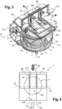
- the invention relates to a suction blower 1 comprising an air inlet housing 21 as illustrated in the Figures 1 and 2 , allowing the flow of at least two different air flows within the blower 1, for example allowing the flow of a recycling air flow FR and an outside air flow FE.
- blower 1 in particular for a heating and/or ventilation and/or air conditioning device for a motor vehicle.
- the suction blower 1 comprises in particular an air generating member such as a turbine 2, intended to be driven in rotation about an axis A, in particular by an electric motor (not visible in the figures), in order to pulse the air.
- the blower 1 generally comprises a housing, commonly called a volute 17, surrounding the turbine 2.
- the blower 1 comprises an additional housing forming an air inlet housing 21.
- the blower 1 also comprises at least one air flow separation member.
- the turbine 2 is for example of generally cylindrical shape, with axis A. In the remainder of the description, the terms axial and radial relate to axis A.
- the turbine 2 has blades 3 at its radially external periphery and internally delimits a cylindrical space.
- the turbine 2 comprises a first axial part 5 called the “upper part” and a second axial part 6 called the “lower part”.
- the first axial part 5 extends from a first end 7 of the turbine 2 to an axially middle zone.
- the second axial part 6 extends from the axially middle zone to a second end 8, opposite the first end 7, of the turbine 2.
- a hub (not shown) is generally attached to the turbine 2 and serves as a deflector for the circulating air flows.
- the hub is, for example, in the form of a part of revolution of axis A.
- a rotating drive shaft (not shown) of the electric motor is, for example, fixed at a central area of the hub. In operation, the motor rotates the hub and the turbine 2.
- top and bottom are defined herein by reference to the figures and are not intended to be limiting.
- the volute 17 surrounding the turbine 2 ensures the channeling of the pulsed air flow. More precisely, an air flow is sucked in and circulated by the turbine 2 and is then extracted from the volute 17 by an outlet 17a (partially shown in the figure 3 ), intended to be connected to an air duct of the heating, ventilation and/or air conditioning device.
- the volute 17 defines a general spiral shape.
- the spiral shape of the volute 17 therefore has a first part of winding(s).
- the shape of the volute 17 then evolves in a more linear manner, thus forming the volute outlet 17a up to an air outlet opening opening, for example, into the air duct of the heating, ventilation and/or air conditioning device.
- the outlet 17a of volute 17 therefore ends with this air outlet opening which is inscribed in a plane, which is shown vertical with reference to the arrangement on the figure 3 .
- the air outlet opening may lie in particular in a plane following the longitudinal axis of the vehicle and the vertical axis.
- the outlet 17a of volute 17 evolves along an axis B. This is an axis transverse to the plane in which the air outlet opening is inscribed.
- the axis B of extension or evolution of the volute outlet 17a is orthogonal to the axis A of rotation of the turbine 2 (as shown diagrammatically in the figure 3 ).
- volute 17 can also at least partially surround the engine (not shown).
- the volute 17 comprises two channels 18, 19 extending respectively opposite the first and second axial parts 5, 6 of the turbine 2.
- channel 18 forms a lower channel opposite the lower part 5 of the turbine 2, and channel 19 an upper channel opposite the upper part 6 of the turbine 2.
- the volute 17 may further comprise a dividing wall (not visible in the figures), for example of annular shape, making it possible to delimit the two channels 18, 19.
- the dividing wall may be arranged so as to separate the volute 17 into two halves, advantageously equal.
- the volute 17 comprises an upper opening 22 allowing the passage of at least one air flow within the blower 1. This upper opening 22 is better visible on the figure 3 .
- the air inlet housing 21 is fixed above the upper opening 22 of the volute 17.
- the air inlet housing 21 comprises an internal space.
- the internal space delimits an air passage section.
- the internal space of the air inlet housing 21 is open downwards with reference to the arrangement on the Figures 5a to 5c , that is, open on the turbine 2 side.
- the air passage section is delimited by a first dimension d1 which corresponds to the depth, a second dimension d2 which corresponds to the width, and the height along the axis A.
- the directions of the dimensions d1 and d2 are shown diagrammatically by arrows on the Figures 1 to 3 .
- the second dimension d2 here extends parallel or substantially parallel to the axis B of the volute outlet 17a.
- the first dimension d1 extends in a direction orthogonal to the axis B of extension of the volute outlet 17a.
- the air inlet housing 21 comprises at least two separate air inlets 24, 26, to allow the flow of different air flows, in particular the recycling air flow FR and the exterior air flow FE, within the blower 1.
- the air inlets 24, 26 extend consecutively in the direction of the depth d1 of the air inlet housing 21.
- Each air inlet 24, 26 extends over the entire width d2 of the air inlet housing 21 and over only a part in the direction of the depth d1.
- the air inlet 24 corresponds to an opening for the passage of the recycling air flow FR and is hereinafter referred to as the recycling air inlet 24.
- the air inlet 26 corresponds to an opening for the passage of the external air flow FE and is hereinafter referred to as the external air inlet 26.
- the air inlets 24 and 26 can be reversed.
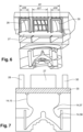
- the air inlet housing 21 further comprises air guide means or members 27, 28, 30 (see figures 2 And 3 ).
- the air guide members 27, 28, 30 can direct air flows of different types, in particular the recycling air flow and the outside air flow, for different operating modes. In particular, they make it possible to direct an air flow into a first air circulation channel, and more generally towards the first axial part 5 of the turbine 2, and/or into a second air circulation channel, and more generally towards the second axial part 6 of the turbine 2.
- the air guide members comprise at least three movable flaps 27, 28, 30.
- a butterfly shutter corresponds to a shutter comprising at least one blade or side wall and a rotation shaft located in the center of the shutter, for example in the case where there are two side walls, the rotation shaft is arranged between the two side walls.
- a flag shutter corresponds to a shutter comprising at least one blade and a rotation shaft located at one end of the shutter.
- a drum shutter corresponds to a shutter comprising two side walls inscribed in two separate planes and parallel to each other with a curved wall used to prevent the passage of the air flow connecting the two side walls and a rotation shaft used to induce the rotational movement via an actuator also connects the two side walls.
- the curved wall and the rotation shaft form a continuity of material between the two side walls.
- the air guide members here comprise three shutters (better visible on the figure 3 ) including a central flap 27, and two side flaps 28 and 30 on either side of the central flap 27. These are advantageously flaps of the same nature, such as drum flaps.
- the central flap 27 and the side flaps 28, 30 are arranged between the recycling air inlet 24 and the outside air inlet 26 so as to be able to at least partially or completely block these two air inlets 24, 26 depending on the operating mode.
- the central flap 27 and the side flaps 28, 30 are arranged so as to be driven in rotation about a pivot axis.
- the pivot axis is a common axis 33 for the three flaps 27, 28, 30.
- the three flaps 27, 28, 30 are coaxial and movable about a single pivot axis 33.
- the pivot axis 33 is parallel to the axis B, which corresponds to the extension axis of the volute outlet 17a or in other words to the flow axis of at least one air flow at the outlet of the volute 17.
- pivot axis 33 is orthogonal to the axis A of rotation of the turbine 2.
- the pivot axis 33 is orthogonal to the general direction of entry of the exterior air flows FE and recycling FR.
- the flaps 27, 28 and 30 each extend not over the entire width d2 of the air passage section, but each over a portion of the width d2 of the air passage section in the air inlet housing 21. In other words, these flaps 27, 28, 30 are arranged in three rows between the outside air inlet 26 and the recycling air inlet 24.
- the central flap 27 extends over a portion d27 of the width d2 of the air passage section in the air inlet housing 21 greater than the portion d28,d30 of the width d2 covered by the two side flaps 28,30 as illustrated in figure 6 . More specifically, the central flap 27 extends over more than half of the width d2 of the air passage section (d27> d28+d30). We can cite as an example that the central flap 27 extends over a range comprised in the interval [50% - 80%] of the width d2 of the air passage section.
- the central flap 27 extends, or covers, 105 mm of the width d2, and each side flap covers 24.5 mm of the width d2.
- Each flap 27, 28, 30 has a travel between two extreme positions, a first extreme position, in which the flap closes the outside air inlet 26, and a second extreme position, in which the flap closes the recycling air inlet 24.
- the side flaps 28, 30 come to bear against at least one stop, for example at the level of edges, support walls, such as a curved wall, a flat wall, or even a stop overmolded on a flat wall, of the air inlet housing 21.
- the side flaps 28, 30 close the recirculation air inlet 24 and the central flap 27 closes the outside air inlet 26.
- the recirculation air flow therefore represents 70% of the incoming air flow and therefore the passenger compartment is warmed up more quickly while avoiding fogging of the windshield since 30% of the incoming air flow, corresponding to the outside air flow, is directed towards the passenger compartment. This arrangement considerably improves the vehicle's "warm-up".
- the blower 1, and in particular the air guide members, further comprise kinematic means between their respective strokes so as to synchronize the movements of at least some flaps, thus limiting the number of actuators required.
- the kinematic means comprise, for example, cam tracks with several output pinions, connecting rods between the flaps, etc.
- a common actuator can in particular simultaneously control the different flaps.
- the air flow separation member(s) are arranged fixedly in the blower 1.
- the air flow separation member(s) comprise a separating partition 14 making it possible to separate the first air flow and the second air flow, this separating partition 14 being more visible on the figure 3 .
- the separating partition 14 is mounted within the blower 1 and extends at least partly into the internal space of the turbine 2.
- the separating partition 14 extends for example from a middle zone of the turbine 2 between the two axial parts 5, 6 towards the air inlet housing 21 (not visible in the figure 3 ).
- the dividing wall 14 extends from the middle zone of the turbine 2 to a point located beyond the second end 8.
- the dividing wall 14 is fixedly mounted relative to the volute 17. It may be an added part or molded with the volute 17.
- the dividing wall 14 is arranged to separate the air flows into a central flow circulating inside the dividing wall 14 and a peripheral flow circulating around the dividing wall 14.
- the central flow corresponds to the first air flow.
- the peripheral flow corresponds to the second air flow.
- the dividing partition 14 delimits an internal channel forming at least part of the first air circulation channel, the second air circulation channel extending outside the dividing partition 14.
- the separating partition 14 advantageously has a shape of revolution.
- This separating partition 14 can be coaxial with the turbine 2.
- the separating partition 14 has a shape of revolution around the axis A of rotation of the turbine 2.
- the diameter of the separating partition 14 is advantageously chosen to guarantee the distribution of the air flows when they are different, in the volute 17 and subsequently in the motor vehicle, in desired proportions, for example in a non-limiting manner of the order of 60% in the upper channel 19 and of the order of 40% in the lower channel 18.
- the separating partition 14 may have a general shape that is at least partly flared to direct the air flows towards the blades 3 of the turbine 2.
- the separating partition 14 may comprise a cylindrical or tubular upper or upstream portion 15.
- the cylindrical upper portion 15 extends between an intermediate portion 57 which will be described later and a lower portion of the air inlet housing 21.
- the separating partition 14 may also have a lower or downstream portion that widens downwards.
- the lower portion and more generally the separating partition 14, widens from upstream to downstream.
- the terms upstream and downstream are defined with reference to the direction of air flow through the blower 1.
- Such a lower portion may extend between the intermediate portion 57 and the axially median zone of the turbine 2.
- the lower portion may have a shape of revolution of axis A.
- the radial periphery of the lower portion is less than the radial periphery of the blades 3 of the turbine 2, so as not to hinder the rotation of the blades 3.
- the separating partition 14 further comprises an intermediate portion 57 arranged between the upstream portion 15 and the downstream portion 58 and connecting these two portions, the intermediate portion 57 is arranged at the second end 8 of the turbine 2.
- the intermediate portion 57 is of reduced section relative to the two upstream 14 and downstream 58 portions, in other words it corresponds to a constriction point for the flow of the air flow flowing inside the duct defined by the separating partition 14.
- the duct defined by the separating partition 14 has smaller dimensions along at least two axes, or even three axes, which are orthogonal or the perimeter of the air passage section of the intermediate portion 57 is inscribed in the perimeter of the section of the upstream 14 and downstream 58 portions.
- the air passage section is reduced downstream of the duct. upstream 14 and reduced upstream of the downstream part 58 relative to the air flow.
- the separating partition 14 has a section of the profile comprising at least two inflections, in other words, the separating partition 14 seen in profile with a section in the direction of flow of the air flow has at least two inflections, or change of direction of the separating partition 14, that is to say at least one bend or even two angles each greater than 30°. It can also be said that the separating partition 14 seen in profile with a section in the direction of flow of the air flow has an S-shaped profile.
- the separating partition 14 has an upstream end 141.
- This upstream end 141 notably terminates the upper part 15 on the side opposite the lower part 16.
- the upstream end 141 extends into the air inlet housing 21, notably into the lower part of the air inlet housing 21.
- the upstream end 141 extends over the entire first dimension or depth dl and over only part of the second dimension or width d2.
- air can flow into the lateral passages located between the outer surface of the dividing partition 14 and the inner wall of the air inlet housing 21 or the edge of the upper opening 22 of the volute 17 ( figure 3 ).
- This upstream end 141 is for example of substantially rectangular section.
- the upstream end 141 has an opening 143, in particular central, in the extension of the internal channel of the separating partition 14 forming at least part of the first air circulation channel.
- This opening 143 is delimited by two holding plates 145 allowing the separating partition 14 to be held in the blower 1.
- the upstream end 141 In the state mounted in the volute 17, the upstream end 141, in particular its holding plates 145, come to bear against the volute 17, more precisely against a wall or an upper edge of the volute 17.
- the retaining plates 145 have an extent similar to the extent of the central flap 27. In other words, the width of the retaining plates 145 is equal or substantially equal to the width of the central flap 27.
- the upstream end 141 of the separating partition 14 can be connected to the cylindrical upper part 15 by a progressive connection zone.
- the upper opening 22 of the volute 17 allows the passage of the separating partition 14, in particular the upper part 15.
- the internal space of the air inlet housing 21 allows the entry of air into the separating partition 14 and/or into the turbine 2 via the upper opening 22.
- the air flows can flow within the separating partition 14 as well as in lateral passages located between the external surface of the separating partition 14 and the edge of the upper opening 22 of the volute 17.
- the peripheral air flow circulating around the separating partition 14 feeds the upper channel 19 of the volute 17.
- the central flow coming from the inside of the separating partition 14 feeds the lower channel 18 of the volute 17.
- the air flow separation member(s) also include an additional separating partition 39, better visible in the figure 3 .
- the additional partition 39 is arranged in the air inlet housing 21 so as to at least partially surround an end region of the central flap 27 in an extreme position.
- the additional separating partition 39 has at least one stop against which the central flap 27 can end its travel, so as to allow sealed sealing of the exterior air inlet 26 or the recycling air inlet 24.
- the additional separating partition 39 has a base, and in particular a frame 391 forming a base.
- This frame 391 extends mainly in an extension direction orthogonal to the extension axis B of the volute outlet 17a.
- This frame 391 extends mainly in an extension direction orthogonal to the extension axis B of the volute outlet 17a, or in other words orthogonal to the flow axis of at least one air flow at the outlet of the volute 17.
- the frame 391 is arranged opposite the upstream end 141 of the separating partition 14.
- the frame 391 is of a shape complementary to the shape of the upstream end 141 of the separating partition.
- the frame 391 has an outline of a shape similar to the upstream end 141, in this example of substantially rectangular shape.
- the dimensions of the frame 391 are for example equal or substantially equal to the dimensions of the upstream end 141.
- the central flap 27 ends its travel against the lateral sides, in particular the small lateral sides of the frame 391.
- the frame 391 delimits an internal recess 393. This recess 393 allows the passage of air.
- the additional separating partition 39 is symmetrical with respect to the pivot axis 33.
- the additional dividing partition 39 also comprises a belt 395 which extends directly above one of the faces of the frame 391, for example from a central or substantially central region of the frame 391. This belt 395 delimits an internal recess.
- the belt 395 is configured so as to surround the central flap 27, and more precisely an end region of the central flap 27 when it is in one or other of the extreme positions.
- the shape of the belt 395 of the additional dividing partition 39 is complementary to the shape of the central flap 27, in particular of the cross section of the central flap 27.
- the additional separating partition 39 and in particular the belt 395, ensures separation from the side flaps 28, 30.
- the air inlet housing 21 may further comprise at least one filter 35 (see Figures 5a to 5c ).
- This filter 35 is intended to be crossed by the first and second air flows.
- the filter 35 is therefore arranged downstream of the air inlets 24, 26 according to the direction of air flow in the air inlet housing 21.
- the filter 35 is mounted in the air inlet housing 21, in particular in the lower part of the air inlet housing 21, occupying all or almost all of the width d2 and the depth d1 of the air passage section in the internal space of the air inlet housing 21.
- the filter 35 is arranged axially between the separating partition 14 and the air inlets 24, 26.
- the filter 35 is mounted axially between on the one hand the separating partition 14 and on the other hand the additional separating partition 39, and in particular also the coaxial flaps 27, 28, 30.
- Such a filter 35 can be easily dismantled, by opening or removing the air inlet housing 21 accessible for example from the glove compartment of the vehicle.
- the filter 35 is represented by a filter of generally rectangular shape. Of course, this shape is not limiting.
- the filter 35 can be a flat or rounded filter.
- a rectangular filter 35 In the case of a rectangular filter 35, it extends in the lengthwise direction along the second dimension d2 and in the widthwise direction along the first dimension d1.
- the upstream end 141 of the separating partition 14 then extends along the entire width of the filter 35 and over only part of the length of the filter 35.
- the filter 35 may not be arranged in the air inlet housing 21 but may be arranged elsewhere in the heating and/or ventilation and/or air conditioning device.
- the filter 35 may be placed upstream of a heat exchanger of the heating and/or ventilation and/or air conditioning device such as an evaporator.
- the filter 35 comprises air guides (not shown in the figures), comprising for example one or more partitions or separation strips, making it possible to limit or even prevent mixing between the air flows, in particular in an operation of the blower 1 in which separate air flows are sucked in.
- the air guides may be parts added to the filter 35. These air guides are positioned in the continuity of the long sides of the additional separating partition 39, so as to partition the air flows coming from the air inlets.
- several separate filters can be arranged, for example three filters.
- the additional separating partition 39 and the separating partition 14 are made in a single piece.
- FIG. 5a illustrates the first operating mode, 100% recycling, in which only the recycling air FR is drawn into the blower 1, so as to supply the heating, ventilation and/or air conditioning device with recycling air FR.
- Such an operating mode can for example be used in the case of air conditioning (for example in summer). Indeed, in such a case, the humidity present in the air in the passenger compartment tends to condense as it passes through the evaporator allowing the air to be cooled.
- This recycling air is therefore not or only slightly loaded with humidity and can be sent into the passenger compartment, in particular near the windshield.
- the coaxial flaps 27, 28, 30 are in the first extreme position of closing the outside air inlet 26, and leave the recycling air inlet 24 free.
- the recycling air flow FR corresponding to the air taken from the passenger compartment, therefore enters through the recycling air inlet 24, passes through the additional dividing wall 39, the filter 35, the dividing wall 14, the lower part 5 of the turbine 2, and enters the channel 18, the latter opening for example into the passenger compartment of the vehicle at a distance from the windshield.
- another portion of the recycling air flow FR coming from the recycling air inlet 24 passes through the filter 35 and the lateral passages located between the external surface of the dividing wall 14 and the edge of the upper opening 22 of the volute 17, the upper part 6 of the turbine 2 and enters the channel 19, the latter opening for example into the passenger compartment of the vehicle near or directly opposite the windshield.
- the FR recirculation airflow flows through both the first circulation channel and the second circulation channel before entering the passenger compartment.
- FIG. 5b illustrates the second operating mode, 100% fresh, in which only the outside air FE is drawn into the blower 1, so as to supply the heating, ventilation and/or air conditioning device with outside air.
- Such an operating mode can for example be used in the case of heating the outside air (for example in winter or mid-season) while preventing too much mist from forming on the windshield.
- the coaxial flaps 27, 28, 30 are in the second extreme position of closing the recycling air inlet 24, and leave the outside air inlet 26 free.
- the outside air flow FE entering from the outside air inlet 26, passes through the additional separating partition 39, the filter 35, the separating partition 14, the lower part 5 of the turbine 2, and enters the channel 18, the latter opening into the passenger compartment of the vehicle, for example at a distance from the windshield.
- the external air flow FE also flows, via the outside of the separating partition 14, into the upper part 6 of the turbine 2 and enters the channel 19 last opening into the passenger compartment of the vehicle, for example near or directly opposite the windshield.
- the outside air flow FE flows through both the first circulation channel and the second circulation channel before entering the passenger compartment.
- FIG. 5c illustrates the third operating mode, 50/50, in which outside air FE and recycling air FR are drawn into the blower 1, so as to supply the heating, ventilation and/or air conditioning device with outside and recycling air, the blower 1 making it possible to generate two separate air flows.
- Such an operating mode can for example be used in the event of air heating (for example in winter or mid-season) and makes it possible to reduce the time required to reach a set temperature, the temperature of the air taken from the passenger compartment being higher than the temperature of the outside air, without too much mist forming on the windshield.
- the air guide members make it possible to direct the first air flow, here the recycling air flow FR, into the first air circulation channel and the second air flow, here the outside air flow FE, into the second air circulation channel.
- the central flap 27 is in the first extreme position for closing the outside air inlet 26.
- the side flaps 28, 30 are in the second extreme position for closing the recycling air inlet 24.
- the outside air flow FE can flow within the blower 1 through the outside air inlet 26 to be guided towards the outside of the dividing wall 14, and the recycling air flow FR can also flow into the blower 1 through the central flap 27 which guides the recycling air flow FR towards the inside of the additional dividing wall 39 and then of the dividing wall 14.
- the air flows are separated into a central flow which is the recycling air flow FR and a peripheral flow which is the outside air flow FE.
- the recycling air flow FR passes through the additional dividing wall 39, the filter 35 and the dividing wall 14, the lower part 5 of the turbine 2, and enters the channel 18, the latter opening for example into the passenger compartment of the vehicle at a distance from the windshield.
- the outside air flow FE flows, via the outside of the dividing wall 14, into the lower part high 6 of turbine 2 and enters channel 19, the latter opening for example into the passenger compartment of the vehicle near or directly opposite the windshield.
- the three coaxial flaps 27, 28, 30, in particular in addition to the separating partition 14, ensure the partitioning of the air inlet housing into three distinct parts, separated by the coaxial flaps 27, 28, 30 and the additional separating partition 39.
- the coaxial flaps 27, 28, 30 make it possible to limit the number of partitions for separating the air flows.
- the upstream end 141 of the separating partition 14 is rotated by approximately 90° relative to the solutions of the prior art, so as to optimize this partitioning.
- the upstream end 141 therefore extends in the depth direction of the air inlet housing 21 which also corresponds to the width direction of the filter 35 when it is provided, and no longer in the length direction of the filter 35 as in the solutions of the prior art.
Landscapes
- Engineering & Computer Science (AREA)
- Mechanical Engineering (AREA)
- Physics & Mathematics (AREA)
- Thermal Sciences (AREA)
- General Engineering & Computer Science (AREA)
- Structures Of Non-Positive Displacement Pumps (AREA)
- Air-Conditioning For Vehicles (AREA)
Claims (8)
- Ansauggebläse (1), insbesondere für eine Heizungs-, Lüftungs- und/oder Klimatisierungsvorrichtung eines Kraftfahrzeugs, wobei das Gebläse (1) umfasst:• ein Laufrad (2), das dazu ausgestaltet ist, um eine Achse (A) drehangetrieben zu werden, und mindestens einen ersten Teil (5), "Oberteil" genannt, und einen zweiten Teil (6), "Unterteil" genannt, aufweist,• ein Spiralgehäuse (17), welches das Laufrad (2) umgibt und einen Spiralgehäuseauslass (17a) aufweist, der sich entlang einer Achse (B) erstreckt, undbeinhaltend:- ein Lufteinlassgehäuse (21),- mindestens zwei Lufteinlässe (24, 26), die verschieden sind und sich über eine Breite (d2) des Lufteinlassgehäuses 21 erstrecken, und- Luftleiteinrichtungen (27, 28, 30), die dazu ausgestaltet sind, mindestens einen Luftstrom zu lenken, der dazu bestimmt ist, in das Lufteinlassgehäuse (21) eingelassen zu werden,wobei die Luftleiteinrichtungen mindestens drei Klappen (27, 28, 30) beinhalten, darunter eine zentrale Klappe (27) und zwei seitliche Klappen (28, 30), die beidseits der zentralen Klappe (27) angeordnet sind, wobei die Klappen (27, 28, 30) zwischen den beiden verschiedenen Lufteinlässen (24, 26) des Lufteinlassgehäuses (21) auf um eine einzige Schwenkachse (33) bewegliche Weise angeordnet sind, wobei sich die zentrale Klappe (27) über einen Abschnitt (d27) der Breite (d2) des Lufteinlassgehäuses (21) erstreckt, der größer als der Abschnitt (d28,d30) der Breite (d2) ist, in dem sich die beiden seitlichen Klappen (28,30) erstrecken,wobei das Gebläse (1) ferner eine Trennwand (14) umfasst, die sich mindestens teilweise in dem Laufrad (2) erstreckt, so dass sie einen ersten Luftstrom, der dazu bestimmt ist, den ersten axialen Teil (5) des Laufrads (2) zu durchströmen, und einen zweiten Luftstrom, der dazu bestimmt ist, den zweiten axialen Teil (6) des Laufrads (2) zu durchströmen, trennt, dadurch gekennzeichnet, dass die Schwenkachse (33) der Klappen (27, 28, 30) parallel zu der Erstreckungsachse (B) des Spiralgehäuseauslasses (17a) ist und die Trennwand (14), im Profil mit einem Schnitt in der Strömungsrichtung des Luftstroms betrachtet, mindestens zwei Biegungen oder Richtungsänderungen der Trennwand (14) aufweist, d. h. zwei Winkel von jeweils mehr als 30°.
- Ansauggebläse (1) nach dem vorhergehenden Anspruch, bei dem die Klappen (27, 28, 30) jeweils zwischen einer ersten Endlage, in der die Klappe (27, 28, 30) einen ersten Lufteinlass (26) verschließt, und einer zweiten Endlage, in der die Klappe (27, 28, 30) den anderen Lufteinlass (24) verschließt, beweglich angeordnet sind.
- Ansauggebläse (1) nach einem der vorhergehenden Ansprüche, bei dem die koaxialen Klappen (27, 28, 30) trommelartig sind.
- Ansauggebläse (1) nach einem der vorhergehenden Ansprüche, bei dem sich die zentrale Klappe (27) über einen Abschnitt (d27) der Breite (d2) des Lufteinlassgehäuses (21) erstreckt, der in einem Intervall zwischen 60 % und 80 % der Breite (d2) des Lufteinlassgehäuses (21), bevorzugt 70 %, liegt.
- Ansauggebläse (1) nach einem der vorhergehenden Ansprüche, bei dem die Trennwand (14) einen mittleren Teil (57) umfasst, der zwischen einem stromaufwärtigen Teil (15) und einem stromabwärtigen Teil (58) so angeordnet ist, dass er diese beiden Teile verbindet, wobei der mittlere Teil (57) an einem Ende (8) des Laufrads (2) angeordnet ist, wobei der mittlere Teil (57) einen in Bezug auf die beiden stromaufwärtigen (14) und stromabwärtigen (58) Teile reduzierten Querschnitt aufweist.
- Ansauggebläse (1) nach dem vorhergehenden Anspruch, bei dem die Trennwand (14) ein stromaufwärtiges Ende (141) aufweist, das sich in dem Lufteinlassgehäuse (21) entlang einer Haupterstreckungsrichtung senkrecht zu der Erstreckungsachse (B) des Spiralgehäuseauslasses (17a) und zu der Drehachse (A) des Laufrads (2) erstreckt, und bei dem- das Lufteinlassgehäuse (21) einen Innenraum umfasst, der einen Luftdurchgangsquerschnitt begrenzt, der ein erstes Maß (d1) entlang einer Richtung senkrecht zu der Erstreckungsachse (B) des Spiralgehäuseauslasses (17a) und ein zweites Maß (d2) parallel zu der Erstreckungsachse (B) des Spiralgehäuseauslasses (17a) hat, und bei dem- das stromaufwärtige Ende (141) der Trennwand (14) sich über das gesamte erste Maß (d1) und über einen Teil des zweiten Maßes (d2) erstreckt.
- Ansauggebläse (1) nach einem der vorhergehenden Ansprüche, beinhaltend ferner eine zusätzliche Trennwand (39), die in dem Lufteinlassgehäuse (21) so angeordnet ist, dass sie mindestens teilweise eine Endregion der zentralen Klappe (27) in einer Endlage umgibt.
- Ansauggebläse (1) nach dem vorhergehenden Anspruch, bei dem die zusätzliche Trennwand (39) einen Rahmen (391) aufweist, der sich hauptsächlich entlang einer Erstreckungsrichtung senkrecht zu der Erstreckungsachse (B) des Spiralgehäuseauslasses (17a) erstreckt, und lotrecht zu dem sich eine Einfassung (395) so erstreckt, dass sie mindestens teilweise eine Endregion der zentralen Klappe (27) in einer Endlage umgibt.
Applications Claiming Priority (2)
| Application Number | Priority Date | Filing Date | Title |
|---|---|---|---|
| FR1858755A FR3086208B1 (fr) | 2018-09-25 | 2018-09-25 | Boitier d'entree d'air et pulseur pour dispositif de chauffage, ventilation et/ou climatisation pour vehicule automobile correspondant |
| PCT/FR2019/052070 WO2020065164A1 (fr) | 2018-09-25 | 2019-09-09 | Boitier d'entree d'air et pulseur pour dispositif de chauffage, ventilation et/ou climatisation pour vehicule automobile correspondant |
Publications (2)
| Publication Number | Publication Date |
|---|---|
| EP3856552A1 EP3856552A1 (de) | 2021-08-04 |
| EP3856552B1 true EP3856552B1 (de) | 2024-10-16 |
Family
ID=65243865
Family Applications (1)
| Application Number | Title | Priority Date | Filing Date |
|---|---|---|---|
| EP19790637.3A Active EP3856552B1 (de) | 2018-09-25 | 2019-09-09 | Gebläse für eine heizungs-, -lüftungs- und/oder -klimatisierungsvorrichtung eines kraftfahrzeugs |
Country Status (6)
| Country | Link |
|---|---|
| US (1) | US11833881B2 (de) |
| EP (1) | EP3856552B1 (de) |
| JP (1) | JP7245915B2 (de) |
| CN (1) | CN112888585B (de) |
| FR (1) | FR3086208B1 (de) |
| WO (1) | WO2020065164A1 (de) |
Families Citing this family (3)
| Publication number | Priority date | Publication date | Assignee | Title |
|---|---|---|---|---|
| JP7410896B2 (ja) * | 2021-02-01 | 2024-01-10 | 株式会社ヴァレオジャパン | 遠心送風機 |
| US12600197B2 (en) | 2022-03-29 | 2026-04-14 | Mahle International Gmbh | HVAC module |
| WO2025020137A1 (zh) * | 2023-07-26 | 2025-01-30 | 浙江极氪智能科技有限公司 | 空调进风口结构与车辆 |
Citations (1)
| Publication number | Priority date | Publication date | Assignee | Title |
|---|---|---|---|---|
| CN208118890U (zh) * | 2018-04-25 | 2018-11-20 | 南方英特空调有限公司 | 一种内外气双层流汽车空调进风箱总成 |
Family Cites Families (18)
| Publication number | Priority date | Publication date | Assignee | Title |
|---|---|---|---|---|
| KR100381751B1 (ko) * | 2001-03-12 | 2003-04-26 | 칼소닉 칸세이 가부시끼가이샤 | 차량용 공기 조화 장치 |
| KR100772487B1 (ko) * | 2001-12-21 | 2007-11-01 | 한라공조주식회사 | 차량 공조용 블로어 유닛 및 그 제조방법 |
| JP3988562B2 (ja) * | 2002-07-19 | 2007-10-10 | 株式会社デンソー | 車両用空調装置の内外気切替装置 |
| JP4539434B2 (ja) | 2005-05-17 | 2010-09-08 | 株式会社デンソー | 内外気切替装置およびその製造方法 |
| JP5556689B2 (ja) * | 2011-02-14 | 2014-07-23 | 株式会社デンソー | 送風機ユニット |
| FR2991635B1 (fr) * | 2012-06-08 | 2016-03-18 | Valeo Systemes Thermiques | Installation de conditionnement thermique d'un habitacle d'un vehicule, notamment un vehicule electrique. |
| JP5935721B2 (ja) * | 2013-03-05 | 2016-06-15 | 株式会社デンソー | 車両用空調装置 |
| FR3014029B1 (fr) * | 2013-12-04 | 2015-12-18 | Valeo Systemes Thermiques | Pulseur d'aspiration destine a un dispositif de chauffage, ventilation et/ou climatisation d'un vehicule automobile |
| DE102014221955B4 (de) * | 2014-10-28 | 2017-10-19 | Mahle International Gmbh | Klimagerät |
| US10675938B2 (en) * | 2014-12-17 | 2020-06-09 | Hanon Systems | Air conditioner for vehicle and controlling method thereof |
| JP6576891B2 (ja) | 2016-09-02 | 2019-09-18 | 株式会社ヴァレオジャパン | 車両用空調装置のための遠心送風機 |
| KR101836694B1 (ko) * | 2016-09-12 | 2018-03-08 | 현대자동차주식회사 | 내-외기 분리 유동 제어가 가능한 자동차용 공조 장치 |
| US10723196B2 (en) * | 2016-12-16 | 2020-07-28 | Air International (Us) Inc. | HVAC system inlet assembly |
| FR3069489B1 (fr) | 2017-07-28 | 2019-11-01 | Valeo Systemes Thermiques | Pulseur et dispositif de chauffage, ventilation et/ou climatisation pour vehicule automobile correspondant |
| FR3069616B1 (fr) | 2017-07-28 | 2019-12-27 | Valeo Systemes Thermiques | Boitier d’entree d’air et pulseur pour dispositif de chauffage, ventilation et/ou climatisation pour vehicule automobile correspondant |
| FR3076768B1 (fr) | 2018-01-12 | 2019-12-13 | Valeo Systemes Thermiques | Boitier d'entree d'air et pulseur pour dispositif de chauffage, ventilation et/ou climatisation pour vehicule automobile correspondant |
| FR3076767B1 (fr) | 2018-01-12 | 2019-12-13 | Valeo Systemes Thermiques | Boitier d'entree d'air et pulseur pour dispositif de chauffage, ventilation et/ou climatisation pour vehicule automobile correspondant |
| JP7003902B2 (ja) * | 2018-12-14 | 2022-02-04 | 株式会社デンソー | 遠心ファン、遠心送風機 |
-
2018
- 2018-09-25 FR FR1858755A patent/FR3086208B1/fr active Active
-
2019
- 2019-09-09 EP EP19790637.3A patent/EP3856552B1/de active Active
- 2019-09-09 JP JP2021541321A patent/JP7245915B2/ja active Active
- 2019-09-09 CN CN201980068607.4A patent/CN112888585B/zh active Active
- 2019-09-09 US US17/278,944 patent/US11833881B2/en active Active
- 2019-09-09 WO PCT/FR2019/052070 patent/WO2020065164A1/fr not_active Ceased
Patent Citations (1)
| Publication number | Priority date | Publication date | Assignee | Title |
|---|---|---|---|---|
| CN208118890U (zh) * | 2018-04-25 | 2018-11-20 | 南方英特空调有限公司 | 一种内外气双层流汽车空调进风箱总成 |
Also Published As
| Publication number | Publication date |
|---|---|
| US11833881B2 (en) | 2023-12-05 |
| JP2022501270A (ja) | 2022-01-06 |
| US20220032727A1 (en) | 2022-02-03 |
| FR3086208A1 (fr) | 2020-03-27 |
| JP7245915B2 (ja) | 2023-03-24 |
| WO2020065164A1 (fr) | 2020-04-02 |
| FR3086208B1 (fr) | 2020-12-18 |
| CN112888585A (zh) | 2021-06-01 |
| CN112888585B (zh) | 2024-10-01 |
| EP3856552A1 (de) | 2021-08-04 |
Similar Documents
| Publication | Publication Date | Title |
|---|---|---|
| EP3652006B1 (de) | Gebläse für eine kraftfahrzeugheizungs-, lüftungs- und / oder klimaanlage | |
| EP3652007B1 (de) | Gebläse und entsprechende heizungs-, lüftungs- oder klimaanlage für ein kraftfahrzeug | |
| EP3077678B1 (de) | Saugimpulsgeber für heizungs-, klima- und lüftungstechnische vorrichtung eines kraftfahrzeugs | |
| WO2017103358A1 (fr) | Pulseur d'aspiration destine a un dispositif de chauffage, ventilation et/ou climatisation d'un vehicule automobile et dispositif de chauffage, ventilation et/ou climatisation | |
| EP3856552B1 (de) | Gebläse für eine heizungs-, -lüftungs- und/oder -klimatisierungsvorrichtung eines kraftfahrzeugs | |
| FR2750461A1 (fr) | Unite a soufflante et climatiseur de vehicule l'employant | |
| FR3072054B1 (fr) | Boitier d'entree d'air, et pulseur d'aspiration et dispositif de chauffage, ventilation et/ou climatisation pour vehicule automobile correspondants | |
| EP3921193B1 (de) | Heizungs-, lüftungs- und/oder klimatisierungsvorrichtung für ein kraftfahrzeug | |
| EP2889168B1 (de) | Vorrichtung zum Heizen, Belüften und/oder Klimatisieren | |
| WO2018020105A1 (fr) | Dispositif de chauffage, ventilation et/ou climatisation pour vehicule automobile | |
| EP3737572B1 (de) | Lufteinlassgehäuse und gebläse für eine entsprechende heizungs-, lüftungs- und/oder klimatisierungsvorrichtung eines kraftfahrzeugs | |
| EP3737573B1 (de) | Lufteinlassgehäuse und gebläse für eine entsprechende heizungs-, -lüftungs- und/oder -klimatisierungsvorrichtung eines kraftfahrzeugs | |
| WO2018020106A1 (fr) | Organe de regulation d'un flux d'air pour un dispositif de chauffage, ventilation et/ou climatisation pour vehicule automobile | |
| EP3481655B1 (de) | Heizungs-, lüftungs- und/oder klimatisierungsvorrichtung für ein kraftfahrzeug | |
| FR3069491B1 (fr) | Filtre, boitier d'entree d'air, et pulseur, notamment pour dispositif de chauffage, ventilation et/ou climatisation pour vehicule automobile, correspondant | |
| FR3054488A1 (fr) | Dispositif de chauffage, ventilation et/ou climatisation pour vehicule automobile | |
| FR3066581A1 (fr) | Pulseur d'aspiration destine a un dispositif de chauffage, ventilation et/ou climatisation d'un vehicule automobile et dispositif de chauffage, ventilation et/ou climatisation | |
| EP2889169B1 (de) | Vorrichtung zum Heizen, Belüften und/oder Klimatisieren | |
| WO2020084265A1 (fr) | Dispositif de chauffage, ventilation et/ou climatisation pour vehicule automobile | |
| WO2023227554A1 (fr) | Module d'entrée d'air, dispositif de chauffage, ventilation et/ou climatisation et véhicule correspondants | |
| WO2023227555A1 (fr) | Module d'entrée d'air et dispositif de chauffage, ventilation et/ou climatisation correspondant | |
| FR3100161A1 (fr) | Dispositif de chauffage, ventilation et/ou climatisation pour véhicule automobile |
Legal Events
| Date | Code | Title | Description |
|---|---|---|---|
| STAA | Information on the status of an ep patent application or granted ep patent |
Free format text: STATUS: UNKNOWN |
|
| STAA | Information on the status of an ep patent application or granted ep patent |
Free format text: STATUS: THE INTERNATIONAL PUBLICATION HAS BEEN MADE |
|
| PUAI | Public reference made under article 153(3) epc to a published international application that has entered the european phase |
Free format text: ORIGINAL CODE: 0009012 |
|
| STAA | Information on the status of an ep patent application or granted ep patent |
Free format text: STATUS: REQUEST FOR EXAMINATION WAS MADE |
|
| 17P | Request for examination filed |
Effective date: 20210318 |
|
| AK | Designated contracting states |
Kind code of ref document: A1 Designated state(s): AL AT BE BG CH CY CZ DE DK EE ES FI FR GB GR HR HU IE IS IT LI LT LU LV MC MK MT NL NO PL PT RO RS SE SI SK SM TR |
|
| DAV | Request for validation of the european patent (deleted) | ||
| DAX | Request for extension of the european patent (deleted) | ||
| STAA | Information on the status of an ep patent application or granted ep patent |
Free format text: STATUS: EXAMINATION IS IN PROGRESS |
|
| 17Q | First examination report despatched |
Effective date: 20220429 |
|
| P01 | Opt-out of the competence of the unified patent court (upc) registered |
Effective date: 20230528 |
|
| GRAP | Despatch of communication of intention to grant a patent |
Free format text: ORIGINAL CODE: EPIDOSNIGR1 |
|
| STAA | Information on the status of an ep patent application or granted ep patent |
Free format text: STATUS: GRANT OF PATENT IS INTENDED |
|
| INTG | Intention to grant announced |
Effective date: 20240507 |
|
| GRAS | Grant fee paid |
Free format text: ORIGINAL CODE: EPIDOSNIGR3 |
|
| GRAA | (expected) grant |
Free format text: ORIGINAL CODE: 0009210 |
|
| STAA | Information on the status of an ep patent application or granted ep patent |
Free format text: STATUS: THE PATENT HAS BEEN GRANTED |
|
| AK | Designated contracting states |
Kind code of ref document: B1 Designated state(s): AL AT BE BG CH CY CZ DE DK EE ES FI FR GB GR HR HU IE IS IT LI LT LU LV MC MK MT NL NO PL PT RO RS SE SI SK SM TR |
|
| REG | Reference to a national code |
Ref country code: GB Ref legal event code: FG4D Free format text: NOT ENGLISH |
|
| REG | Reference to a national code |
Ref country code: CH Ref legal event code: EP |
|
| REG | Reference to a national code |
Ref country code: IE Ref legal event code: FG4D Free format text: LANGUAGE OF EP DOCUMENT: FRENCH |
|
| REG | Reference to a national code |
Ref country code: DE Ref legal event code: R096 Ref document number: 602019060541 Country of ref document: DE |
|
| REG | Reference to a national code |
Ref country code: LT Ref legal event code: MG9D |
|
| REG | Reference to a national code |
Ref country code: NL Ref legal event code: MP Effective date: 20241016 |
|
| REG | Reference to a national code |
Ref country code: AT Ref legal event code: MK05 Ref document number: 1732667 Country of ref document: AT Kind code of ref document: T Effective date: 20241016 |
|
| PG25 | Lapsed in a contracting state [announced via postgrant information from national office to epo] |
Ref country code: NL Free format text: LAPSE BECAUSE OF FAILURE TO SUBMIT A TRANSLATION OF THE DESCRIPTION OR TO PAY THE FEE WITHIN THE PRESCRIBED TIME-LIMIT Effective date: 20241016 |
|
| PG25 | Lapsed in a contracting state [announced via postgrant information from national office to epo] |
Ref country code: NL Free format text: LAPSE BECAUSE OF FAILURE TO SUBMIT A TRANSLATION OF THE DESCRIPTION OR TO PAY THE FEE WITHIN THE PRESCRIBED TIME-LIMIT Effective date: 20241016 |
|
| PG25 | Lapsed in a contracting state [announced via postgrant information from national office to epo] |
Ref country code: PT Free format text: LAPSE BECAUSE OF FAILURE TO SUBMIT A TRANSLATION OF THE DESCRIPTION OR TO PAY THE FEE WITHIN THE PRESCRIBED TIME-LIMIT Effective date: 20250217 Ref country code: IS Free format text: LAPSE BECAUSE OF FAILURE TO SUBMIT A TRANSLATION OF THE DESCRIPTION OR TO PAY THE FEE WITHIN THE PRESCRIBED TIME-LIMIT Effective date: 20250216 Ref country code: HR Free format text: LAPSE BECAUSE OF FAILURE TO SUBMIT A TRANSLATION OF THE DESCRIPTION OR TO PAY THE FEE WITHIN THE PRESCRIBED TIME-LIMIT Effective date: 20241016 |
|
| PG25 | Lapsed in a contracting state [announced via postgrant information from national office to epo] |
Ref country code: FI Free format text: LAPSE BECAUSE OF FAILURE TO SUBMIT A TRANSLATION OF THE DESCRIPTION OR TO PAY THE FEE WITHIN THE PRESCRIBED TIME-LIMIT Effective date: 20241016 |
|
| PG25 | Lapsed in a contracting state [announced via postgrant information from national office to epo] |
Ref country code: BG Free format text: LAPSE BECAUSE OF FAILURE TO SUBMIT A TRANSLATION OF THE DESCRIPTION OR TO PAY THE FEE WITHIN THE PRESCRIBED TIME-LIMIT Effective date: 20241016 |
|
| PG25 | Lapsed in a contracting state [announced via postgrant information from national office to epo] |
Ref country code: ES Free format text: LAPSE BECAUSE OF FAILURE TO SUBMIT A TRANSLATION OF THE DESCRIPTION OR TO PAY THE FEE WITHIN THE PRESCRIBED TIME-LIMIT Effective date: 20241016 |
|
| PG25 | Lapsed in a contracting state [announced via postgrant information from national office to epo] |
Ref country code: NO Free format text: LAPSE BECAUSE OF FAILURE TO SUBMIT A TRANSLATION OF THE DESCRIPTION OR TO PAY THE FEE WITHIN THE PRESCRIBED TIME-LIMIT Effective date: 20250116 |
|
| PG25 | Lapsed in a contracting state [announced via postgrant information from national office to epo] |
Ref country code: AT Free format text: LAPSE BECAUSE OF FAILURE TO SUBMIT A TRANSLATION OF THE DESCRIPTION OR TO PAY THE FEE WITHIN THE PRESCRIBED TIME-LIMIT Effective date: 20241016 Ref country code: GR Free format text: LAPSE BECAUSE OF FAILURE TO SUBMIT A TRANSLATION OF THE DESCRIPTION OR TO PAY THE FEE WITHIN THE PRESCRIBED TIME-LIMIT Effective date: 20250117 Ref country code: LV Free format text: LAPSE BECAUSE OF FAILURE TO SUBMIT A TRANSLATION OF THE DESCRIPTION OR TO PAY THE FEE WITHIN THE PRESCRIBED TIME-LIMIT Effective date: 20241016 |
|
| PG25 | Lapsed in a contracting state [announced via postgrant information from national office to epo] |
Ref country code: PL Free format text: LAPSE BECAUSE OF FAILURE TO SUBMIT A TRANSLATION OF THE DESCRIPTION OR TO PAY THE FEE WITHIN THE PRESCRIBED TIME-LIMIT Effective date: 20241016 |
|
| PG25 | Lapsed in a contracting state [announced via postgrant information from national office to epo] |
Ref country code: RS Free format text: LAPSE BECAUSE OF FAILURE TO SUBMIT A TRANSLATION OF THE DESCRIPTION OR TO PAY THE FEE WITHIN THE PRESCRIBED TIME-LIMIT Effective date: 20250116 |
|
| PG25 | Lapsed in a contracting state [announced via postgrant information from national office to epo] |
Ref country code: SM Free format text: LAPSE BECAUSE OF FAILURE TO SUBMIT A TRANSLATION OF THE DESCRIPTION OR TO PAY THE FEE WITHIN THE PRESCRIBED TIME-LIMIT Effective date: 20241016 |
|
| PG25 | Lapsed in a contracting state [announced via postgrant information from national office to epo] |
Ref country code: DK Free format text: LAPSE BECAUSE OF FAILURE TO SUBMIT A TRANSLATION OF THE DESCRIPTION OR TO PAY THE FEE WITHIN THE PRESCRIBED TIME-LIMIT Effective date: 20241016 |
|
| REG | Reference to a national code |
Ref country code: DE Ref legal event code: R097 Ref document number: 602019060541 Country of ref document: DE |
|
| PG25 | Lapsed in a contracting state [announced via postgrant information from national office to epo] |
Ref country code: EE Free format text: LAPSE BECAUSE OF FAILURE TO SUBMIT A TRANSLATION OF THE DESCRIPTION OR TO PAY THE FEE WITHIN THE PRESCRIBED TIME-LIMIT Effective date: 20241016 |
|
| PG25 | Lapsed in a contracting state [announced via postgrant information from national office to epo] |
Ref country code: RO Free format text: LAPSE BECAUSE OF FAILURE TO SUBMIT A TRANSLATION OF THE DESCRIPTION OR TO PAY THE FEE WITHIN THE PRESCRIBED TIME-LIMIT Effective date: 20241016 |
|
| PG25 | Lapsed in a contracting state [announced via postgrant information from national office to epo] |
Ref country code: SK Free format text: LAPSE BECAUSE OF FAILURE TO SUBMIT A TRANSLATION OF THE DESCRIPTION OR TO PAY THE FEE WITHIN THE PRESCRIBED TIME-LIMIT Effective date: 20241016 |
|
| PG25 | Lapsed in a contracting state [announced via postgrant information from national office to epo] |
Ref country code: CZ Free format text: LAPSE BECAUSE OF FAILURE TO SUBMIT A TRANSLATION OF THE DESCRIPTION OR TO PAY THE FEE WITHIN THE PRESCRIBED TIME-LIMIT Effective date: 20241016 |
|
| PG25 | Lapsed in a contracting state [announced via postgrant information from national office to epo] |
Ref country code: IT Free format text: LAPSE BECAUSE OF FAILURE TO SUBMIT A TRANSLATION OF THE DESCRIPTION OR TO PAY THE FEE WITHIN THE PRESCRIBED TIME-LIMIT Effective date: 20241016 |
|
| PLBE | No opposition filed within time limit |
Free format text: ORIGINAL CODE: 0009261 |
|
| STAA | Information on the status of an ep patent application or granted ep patent |
Free format text: STATUS: NO OPPOSITION FILED WITHIN TIME LIMIT |
|
| PG25 | Lapsed in a contracting state [announced via postgrant information from national office to epo] |
Ref country code: SE Free format text: LAPSE BECAUSE OF FAILURE TO SUBMIT A TRANSLATION OF THE DESCRIPTION OR TO PAY THE FEE WITHIN THE PRESCRIBED TIME-LIMIT Effective date: 20241016 |
|
| 26N | No opposition filed |
Effective date: 20250717 |
|
| PGFP | Annual fee paid to national office [announced via postgrant information from national office to epo] |
Ref country code: DE Payment date: 20250916 Year of fee payment: 7 |
|
| PGFP | Annual fee paid to national office [announced via postgrant information from national office to epo] |
Ref country code: FR Payment date: 20250929 Year of fee payment: 7 |
|
| REG | Reference to a national code |
Ref country code: CH Ref legal event code: H13 Free format text: ST27 STATUS EVENT CODE: U-0-0-H10-H13 (AS PROVIDED BY THE NATIONAL OFFICE) Effective date: 20260425 |