EP3856550B1 - Transportkühleinheit mit externer wechselstromgeneratorstromquelle - Google Patents
Transportkühleinheit mit externer wechselstromgeneratorstromquelle Download PDFInfo
- Publication number
- EP3856550B1 EP3856550B1 EP19783782.6A EP19783782A EP3856550B1 EP 3856550 B1 EP3856550 B1 EP 3856550B1 EP 19783782 A EP19783782 A EP 19783782A EP 3856550 B1 EP3856550 B1 EP 3856550B1
- Authority
- EP
- European Patent Office
- Prior art keywords
- power
- energy storage
- tru
- phase
- generator
- Prior art date
- Legal status (The legal status is an assumption and is not a legal conclusion. Google has not performed a legal analysis and makes no representation as to the accuracy of the status listed.)
- Active
Links
Images


Classifications
-
- B—PERFORMING OPERATIONS; TRANSPORTING
- B60—VEHICLES IN GENERAL
- B60H—ARRANGEMENTS OF HEATING, COOLING, VENTILATING OR OTHER AIR-TREATING DEVICES SPECIALLY ADAPTED FOR PASSENGER OR GOODS SPACES OF VEHICLES
- B60H1/00—Heating, cooling or ventilating devices
- B60H1/00007—Combined heating, ventilating, or cooling devices
- B60H1/00014—Combined heating, ventilating, or cooling devices for load cargos on load transporting vehicles
-
- B—PERFORMING OPERATIONS; TRANSPORTING
- B60—VEHICLES IN GENERAL
- B60H—ARRANGEMENTS OF HEATING, COOLING, VENTILATING OR OTHER AIR-TREATING DEVICES SPECIALLY ADAPTED FOR PASSENGER OR GOODS SPACES OF VEHICLES
- B60H1/00—Heating, cooling or ventilating devices
- B60H1/00357—Air-conditioning arrangements specially adapted for particular vehicles
- B60H1/00364—Air-conditioning arrangements specially adapted for particular vehicles for caravans or trailers
-
- B—PERFORMING OPERATIONS; TRANSPORTING
- B60—VEHICLES IN GENERAL
- B60H—ARRANGEMENTS OF HEATING, COOLING, VENTILATING OR OTHER AIR-TREATING DEVICES SPECIALLY ADAPTED FOR PASSENGER OR GOODS SPACES OF VEHICLES
- B60H1/00—Heating, cooling or ventilating devices
- B60H1/00421—Driving arrangements for parts of a vehicle air-conditioning
- B60H1/00428—Driving arrangements for parts of a vehicle air-conditioning electric
-
- B—PERFORMING OPERATIONS; TRANSPORTING
- B60—VEHICLES IN GENERAL
- B60H—ARRANGEMENTS OF HEATING, COOLING, VENTILATING OR OTHER AIR-TREATING DEVICES SPECIALLY ADAPTED FOR PASSENGER OR GOODS SPACES OF VEHICLES
- B60H1/00—Heating, cooling or ventilating devices
- B60H1/32—Cooling devices
- B60H1/3204—Cooling devices using compression
- B60H1/3232—Cooling devices using compression particularly adapted for load transporting vehicles
-
- B—PERFORMING OPERATIONS; TRANSPORTING
- B60—VEHICLES IN GENERAL
- B60K—ARRANGEMENT OR MOUNTING OF PROPULSION UNITS OR OF TRANSMISSIONS IN VEHICLES; ARRANGEMENT OR MOUNTING OF PLURAL DIVERSE PRIME-MOVERS IN VEHICLES; AUXILIARY DRIVES FOR VEHICLES; INSTRUMENTATION OR DASHBOARDS FOR VEHICLES; ARRANGEMENTS IN CONNECTION WITH COOLING, AIR INTAKE, GAS EXHAUST OR FUEL SUPPLY OF PROPULSION UNITS IN VEHICLES
- B60K25/00—Auxiliary drives
- B60K25/08—Auxiliary drives from a ground wheel, e.g. engaging the wheel tread or rim
-
- B—PERFORMING OPERATIONS; TRANSPORTING
- B60—VEHICLES IN GENERAL
- B60L—PROPULSION OF ELECTRICALLY-PROPELLED VEHICLES; SUPPLYING ELECTRIC POWER FOR AUXILIARY EQUIPMENT OF ELECTRICALLY-PROPELLED VEHICLES; ELECTRODYNAMIC BRAKE SYSTEMS FOR VEHICLES IN GENERAL; MAGNETIC SUSPENSION OR LEVITATION FOR VEHICLES; MONITORING OPERATING VARIABLES OF ELECTRICALLY-PROPELLED VEHICLES; ELECTRIC SAFETY DEVICES FOR ELECTRICALLY-PROPELLED VEHICLES
- B60L1/00—Supplying electric power to auxiliary equipment of vehicles
- B60L1/003—Supplying electric power to auxiliary equipment of vehicles to auxiliary motors, e.g. for pumps, compressors
-
- B—PERFORMING OPERATIONS; TRANSPORTING
- B60—VEHICLES IN GENERAL
- B60L—PROPULSION OF ELECTRICALLY-PROPELLED VEHICLES; SUPPLYING ELECTRIC POWER FOR AUXILIARY EQUIPMENT OF ELECTRICALLY-PROPELLED VEHICLES; ELECTRODYNAMIC BRAKE SYSTEMS FOR VEHICLES IN GENERAL; MAGNETIC SUSPENSION OR LEVITATION FOR VEHICLES; MONITORING OPERATING VARIABLES OF ELECTRICALLY-PROPELLED VEHICLES; ELECTRIC SAFETY DEVICES FOR ELECTRICALLY-PROPELLED VEHICLES
- B60L1/00—Supplying electric power to auxiliary equipment of vehicles
- B60L1/02—Supplying electric power to auxiliary equipment of vehicles to electric heating circuits
-
- B—PERFORMING OPERATIONS; TRANSPORTING
- B60—VEHICLES IN GENERAL
- B60L—PROPULSION OF ELECTRICALLY-PROPELLED VEHICLES; SUPPLYING ELECTRIC POWER FOR AUXILIARY EQUIPMENT OF ELECTRICALLY-PROPELLED VEHICLES; ELECTRODYNAMIC BRAKE SYSTEMS FOR VEHICLES IN GENERAL; MAGNETIC SUSPENSION OR LEVITATION FOR VEHICLES; MONITORING OPERATING VARIABLES OF ELECTRICALLY-PROPELLED VEHICLES; ELECTRIC SAFETY DEVICES FOR ELECTRICALLY-PROPELLED VEHICLES
- B60L50/00—Electric propulsion with power supplied within the vehicle
- B60L50/50—Electric propulsion with power supplied within the vehicle using propulsion power supplied by batteries or fuel cells
- B60L50/60—Electric propulsion with power supplied within the vehicle using propulsion power supplied by batteries or fuel cells using power supplied by batteries
- B60L50/61—Electric propulsion with power supplied within the vehicle using propulsion power supplied by batteries or fuel cells using power supplied by batteries by batteries charged by engine-driven generators, e.g. series hybrid electric vehicles
-
- F—MECHANICAL ENGINEERING; LIGHTING; HEATING; WEAPONS; BLASTING
- F25—REFRIGERATION OR COOLING; COMBINED HEATING AND REFRIGERATION SYSTEMS; HEAT PUMP SYSTEMS; MANUFACTURE OR STORAGE OF ICE; LIQUEFACTION SOLIDIFICATION OF GASES
- F25D—REFRIGERATORS; COLD ROOMS; ICE-BOXES; COOLING OR FREEZING APPARATUS NOT OTHERWISE PROVIDED FOR
- F25D11/00—Self-contained movable devices, e.g. domestic refrigerators
- F25D11/003—Transport containers
-
- F—MECHANICAL ENGINEERING; LIGHTING; HEATING; WEAPONS; BLASTING
- F25—REFRIGERATION OR COOLING; COMBINED HEATING AND REFRIGERATION SYSTEMS; HEAT PUMP SYSTEMS; MANUFACTURE OR STORAGE OF ICE; LIQUEFACTION SOLIDIFICATION OF GASES
- F25D—REFRIGERATORS; COLD ROOMS; ICE-BOXES; COOLING OR FREEZING APPARATUS NOT OTHERWISE PROVIDED FOR
- F25D17/00—Arrangements for circulating cooling fluids; Arrangements for circulating gas, e.g. air, within refrigerated spaces
- F25D17/04—Arrangements for circulating cooling fluids; Arrangements for circulating gas, e.g. air, within refrigerated spaces for circulating air, e.g. by convection
- F25D17/06—Arrangements for circulating cooling fluids; Arrangements for circulating gas, e.g. air, within refrigerated spaces for circulating air, e.g. by convection by forced circulation
-
- B—PERFORMING OPERATIONS; TRANSPORTING
- B60—VEHICLES IN GENERAL
- B60L—PROPULSION OF ELECTRICALLY-PROPELLED VEHICLES; SUPPLYING ELECTRIC POWER FOR AUXILIARY EQUIPMENT OF ELECTRICALLY-PROPELLED VEHICLES; ELECTRODYNAMIC BRAKE SYSTEMS FOR VEHICLES IN GENERAL; MAGNETIC SUSPENSION OR LEVITATION FOR VEHICLES; MONITORING OPERATING VARIABLES OF ELECTRICALLY-PROPELLED VEHICLES; ELECTRIC SAFETY DEVICES FOR ELECTRICALLY-PROPELLED VEHICLES
- B60L2200/00—Type of vehicles
- B60L2200/36—Vehicles designed to transport cargo, e.g. trucks
-
- B—PERFORMING OPERATIONS; TRANSPORTING
- B60—VEHICLES IN GENERAL
- B60L—PROPULSION OF ELECTRICALLY-PROPELLED VEHICLES; SUPPLYING ELECTRIC POWER FOR AUXILIARY EQUIPMENT OF ELECTRICALLY-PROPELLED VEHICLES; ELECTRODYNAMIC BRAKE SYSTEMS FOR VEHICLES IN GENERAL; MAGNETIC SUSPENSION OR LEVITATION FOR VEHICLES; MONITORING OPERATING VARIABLES OF ELECTRICALLY-PROPELLED VEHICLES; ELECTRIC SAFETY DEVICES FOR ELECTRICALLY-PROPELLED VEHICLES
- B60L2210/00—Converter types
- B60L2210/20—AC to AC converters
-
- B—PERFORMING OPERATIONS; TRANSPORTING
- B60—VEHICLES IN GENERAL
- B60L—PROPULSION OF ELECTRICALLY-PROPELLED VEHICLES; SUPPLYING ELECTRIC POWER FOR AUXILIARY EQUIPMENT OF ELECTRICALLY-PROPELLED VEHICLES; ELECTRODYNAMIC BRAKE SYSTEMS FOR VEHICLES IN GENERAL; MAGNETIC SUSPENSION OR LEVITATION FOR VEHICLES; MONITORING OPERATING VARIABLES OF ELECTRICALLY-PROPELLED VEHICLES; ELECTRIC SAFETY DEVICES FOR ELECTRICALLY-PROPELLED VEHICLES
- B60L2210/00—Converter types
- B60L2210/40—DC to AC converters
-
- B—PERFORMING OPERATIONS; TRANSPORTING
- B60—VEHICLES IN GENERAL
- B60P—VEHICLES ADAPTED FOR LOAD TRANSPORTATION OR TO TRANSPORT, TO CARRY, OR TO COMPRISE SPECIAL LOADS OR OBJECTS
- B60P3/00—Vehicles adapted to transport, to carry or to comprise special loads or objects
- B60P3/20—Refrigerated goods vehicles
-
- B—PERFORMING OPERATIONS; TRANSPORTING
- B60—VEHICLES IN GENERAL
- B60Y—INDEXING SCHEME RELATING TO ASPECTS CROSS-CUTTING VEHICLE TECHNOLOGY
- B60Y2200/00—Type of vehicle
- B60Y2200/10—Road Vehicles
- B60Y2200/14—Trucks; Load vehicles, Busses
- B60Y2200/142—Heavy duty trucks
-
- F—MECHANICAL ENGINEERING; LIGHTING; HEATING; WEAPONS; BLASTING
- F25—REFRIGERATION OR COOLING; COMBINED HEATING AND REFRIGERATION SYSTEMS; HEAT PUMP SYSTEMS; MANUFACTURE OR STORAGE OF ICE; LIQUEFACTION SOLIDIFICATION OF GASES
- F25D—REFRIGERATORS; COLD ROOMS; ICE-BOXES; COOLING OR FREEZING APPARATUS NOT OTHERWISE PROVIDED FOR
- F25D2700/00—Means for sensing or measuring; Sensors therefor
- F25D2700/12—Sensors measuring the inside temperature
-
- H—ELECTRICITY
- H02—GENERATION; CONVERSION OR DISTRIBUTION OF ELECTRIC POWER
- H02J—ELECTRIC POWER NETWORKS; CIRCUIT ARRANGEMENTS OR SYSTEMS FOR SUPPLYING OR DISTRIBUTING ELECTRIC POWER; SYSTEMS FOR STORING ELECTRIC ENERGY
- H02J2105/00—Networks for supplying or distributing electric power characterised by their spatial reach or by the load
- H02J2105/30—Networks for supplying or distributing electric power characterised by their spatial reach or by the load the load networks being external to vehicles, i.e. exchanging power with vehicles
- H02J2105/33—Networks for supplying or distributing electric power characterised by their spatial reach or by the load the load networks being external to vehicles, i.e. exchanging power with vehicles exchanging power with road vehicles
-
- H—ELECTRICITY
- H02—GENERATION; CONVERSION OR DISTRIBUTION OF ELECTRIC POWER
- H02J—ELECTRIC POWER NETWORKS; CIRCUIT ARRANGEMENTS OR SYSTEMS FOR SUPPLYING OR DISTRIBUTING ELECTRIC POWER; SYSTEMS FOR STORING ELECTRIC ENERGY
- H02J3/00—Circuit arrangements for AC mains or AC distribution networks
- H02J3/007—Arrangements for selectively connecting one or more loads to one or more power sources or power lines
-
- H—ELECTRICITY
- H02—GENERATION; CONVERSION OR DISTRIBUTION OF ELECTRIC POWER
- H02J—ELECTRIC POWER NETWORKS; CIRCUIT ARRANGEMENTS OR SYSTEMS FOR SUPPLYING OR DISTRIBUTING ELECTRIC POWER; SYSTEMS FOR STORING ELECTRIC ENERGY
- H02J7/00—Circuit arrangements for charging or discharging batteries or for supplying loads from batteries
- H02J7/14—Circuit arrangements for charging or discharging batteries or for supplying loads from batteries for charging batteries from dynamo-electric generators driven at varying speed, e.g. on vehicle
- H02J7/1415—Circuit arrangements for charging or discharging batteries or for supplying loads from batteries for charging batteries from dynamo-electric generators driven at varying speed, e.g. on vehicle with a generator driven by a prime mover other than the motor of a vehicle
-
- H—ELECTRICITY
- H02—GENERATION; CONVERSION OR DISTRIBUTION OF ELECTRIC POWER
- H02J—ELECTRIC POWER NETWORKS; CIRCUIT ARRANGEMENTS OR SYSTEMS FOR SUPPLYING OR DISTRIBUTING ELECTRIC POWER; SYSTEMS FOR STORING ELECTRIC ENERGY
- H02J7/00—Circuit arrangements for charging or discharging batteries or for supplying loads from batteries
- H02J7/14—Circuit arrangements for charging or discharging batteries or for supplying loads from batteries for charging batteries from dynamo-electric generators driven at varying speed, e.g. on vehicle
- H02J7/1438—Circuit arrangements for charging or discharging batteries or for supplying loads from batteries for charging batteries from dynamo-electric generators driven at varying speed, e.g. on vehicle in combination with power supplies for loads other than batteries
-
- H—ELECTRICITY
- H02—GENERATION; CONVERSION OR DISTRIBUTION OF ELECTRIC POWER
- H02J—ELECTRIC POWER NETWORKS; CIRCUIT ARRANGEMENTS OR SYSTEMS FOR SUPPLYING OR DISTRIBUTING ELECTRIC POWER; SYSTEMS FOR STORING ELECTRIC ENERGY
- H02J7/00—Circuit arrangements for charging or discharging batteries or for supplying loads from batteries
- H02J7/865—Battery or charger load switching, e.g. concurrent charging and load supply
-
- H—ELECTRICITY
- H02—GENERATION; CONVERSION OR DISTRIBUTION OF ELECTRIC POWER
- H02J—ELECTRIC POWER NETWORKS; CIRCUIT ARRANGEMENTS OR SYSTEMS FOR SUPPLYING OR DISTRIBUTING ELECTRIC POWER; SYSTEMS FOR STORING ELECTRIC ENERGY
- H02J9/00—Circuit arrangements for emergency or stand-by power supply, e.g. for emergency lighting
- H02J9/04—Circuit arrangements for emergency or stand-by power supply, e.g. for emergency lighting in which the distribution system is disconnected from the normal source and connected to a standby source
- H02J9/06—Circuit arrangements for emergency or stand-by power supply, e.g. for emergency lighting in which the distribution system is disconnected from the normal source and connected to a standby source with automatic change-over, e.g. UPS systems
- H02J9/062—Circuit arrangements for emergency or stand-by power supply, e.g. for emergency lighting in which the distribution system is disconnected from the normal source and connected to a standby source with automatic change-over, e.g. UPS systems for AC powered loads
-
- Y—GENERAL TAGGING OF NEW TECHNOLOGICAL DEVELOPMENTS; GENERAL TAGGING OF CROSS-SECTIONAL TECHNOLOGIES SPANNING OVER SEVERAL SECTIONS OF THE IPC; TECHNICAL SUBJECTS COVERED BY FORMER USPC CROSS-REFERENCE ART COLLECTIONS [XRACs] AND DIGESTS
- Y02—TECHNOLOGIES OR APPLICATIONS FOR MITIGATION OR ADAPTATION AGAINST CLIMATE CHANGE
- Y02B—CLIMATE CHANGE MITIGATION TECHNOLOGIES RELATED TO BUILDINGS, e.g. HOUSING, HOUSE APPLIANCES OR RELATED END-USER APPLICATIONS
- Y02B70/00—Technologies for an efficient end-user side electric power management and consumption
- Y02B70/30—Systems integrating technologies related to power network operation and communication or information technologies for improving the carbon footprint of the management of residential or tertiary loads, i.e. smart grids as climate change mitigation technology in the buildings sector, including also the last stages of power distribution and the control, monitoring or operating management systems at local level
- Y02B70/3225—Demand response systems, e.g. load shedding, peak shaving
-
- Y—GENERAL TAGGING OF NEW TECHNOLOGICAL DEVELOPMENTS; GENERAL TAGGING OF CROSS-SECTIONAL TECHNOLOGIES SPANNING OVER SEVERAL SECTIONS OF THE IPC; TECHNICAL SUBJECTS COVERED BY FORMER USPC CROSS-REFERENCE ART COLLECTIONS [XRACs] AND DIGESTS
- Y02—TECHNOLOGIES OR APPLICATIONS FOR MITIGATION OR ADAPTATION AGAINST CLIMATE CHANGE
- Y02T—CLIMATE CHANGE MITIGATION TECHNOLOGIES RELATED TO TRANSPORTATION
- Y02T10/00—Road transport of goods or passengers
- Y02T10/60—Other road transportation technologies with climate change mitigation effect
- Y02T10/62—Hybrid vehicles
-
- Y—GENERAL TAGGING OF NEW TECHNOLOGICAL DEVELOPMENTS; GENERAL TAGGING OF CROSS-SECTIONAL TECHNOLOGIES SPANNING OVER SEVERAL SECTIONS OF THE IPC; TECHNICAL SUBJECTS COVERED BY FORMER USPC CROSS-REFERENCE ART COLLECTIONS [XRACs] AND DIGESTS
- Y02—TECHNOLOGIES OR APPLICATIONS FOR MITIGATION OR ADAPTATION AGAINST CLIMATE CHANGE
- Y02T—CLIMATE CHANGE MITIGATION TECHNOLOGIES RELATED TO TRANSPORTATION
- Y02T10/00—Road transport of goods or passengers
- Y02T10/60—Other road transportation technologies with climate change mitigation effect
- Y02T10/70—Energy storage systems for electromobility, e.g. batteries
-
- Y—GENERAL TAGGING OF NEW TECHNOLOGICAL DEVELOPMENTS; GENERAL TAGGING OF CROSS-SECTIONAL TECHNOLOGIES SPANNING OVER SEVERAL SECTIONS OF THE IPC; TECHNICAL SUBJECTS COVERED BY FORMER USPC CROSS-REFERENCE ART COLLECTIONS [XRACs] AND DIGESTS
- Y02—TECHNOLOGIES OR APPLICATIONS FOR MITIGATION OR ADAPTATION AGAINST CLIMATE CHANGE
- Y02T—CLIMATE CHANGE MITIGATION TECHNOLOGIES RELATED TO TRANSPORTATION
- Y02T10/00—Road transport of goods or passengers
- Y02T10/60—Other road transportation technologies with climate change mitigation effect
- Y02T10/72—Electric energy management in electromobility
-
- Y—GENERAL TAGGING OF NEW TECHNOLOGICAL DEVELOPMENTS; GENERAL TAGGING OF CROSS-SECTIONAL TECHNOLOGIES SPANNING OVER SEVERAL SECTIONS OF THE IPC; TECHNICAL SUBJECTS COVERED BY FORMER USPC CROSS-REFERENCE ART COLLECTIONS [XRACs] AND DIGESTS
- Y02—TECHNOLOGIES OR APPLICATIONS FOR MITIGATION OR ADAPTATION AGAINST CLIMATE CHANGE
- Y02T—CLIMATE CHANGE MITIGATION TECHNOLOGIES RELATED TO TRANSPORTATION
- Y02T10/00—Road transport of goods or passengers
- Y02T10/80—Technologies aiming to reduce greenhouse gasses emissions common to all road transportation technologies
- Y02T10/88—Optimized components or subsystems, e.g. lighting, actively controlled glasses
-
- Y—GENERAL TAGGING OF NEW TECHNOLOGICAL DEVELOPMENTS; GENERAL TAGGING OF CROSS-SECTIONAL TECHNOLOGIES SPANNING OVER SEVERAL SECTIONS OF THE IPC; TECHNICAL SUBJECTS COVERED BY FORMER USPC CROSS-REFERENCE ART COLLECTIONS [XRACs] AND DIGESTS
- Y04—INFORMATION OR COMMUNICATION TECHNOLOGIES HAVING AN IMPACT ON OTHER TECHNOLOGY AREAS
- Y04S—SYSTEMS INTEGRATING TECHNOLOGIES RELATED TO POWER NETWORK OPERATION, COMMUNICATION OR INFORMATION TECHNOLOGIES FOR IMPROVING THE ELECTRICAL POWER GENERATION, TRANSMISSION, DISTRIBUTION, MANAGEMENT OR USAGE, i.e. SMART GRIDS
- Y04S20/00—Management or operation of end-user stationary applications or the last stages of power distribution; Controlling, monitoring or operating thereof
- Y04S20/20—End-user application control systems
- Y04S20/222—Demand response systems, e.g. load shedding, peak shaving
Definitions
- the subject matter disclosed herein generally relates to transportation refrigeration units, and more specifically to an apparatus and a method for powering transportation refrigeration unit with a generator and an energy storage device.
- Refrigeration systems typically include a compressor, a condenser, an expansion valve, and an evaporator serially connected by refrigerant lines in a closed refrigerant circuit in accord with known refrigerant vapor compression cycles.
- a power unit such as a combustion engine, drives the compressor of the refrigeration unit, and may be diesel powered, natural gas powered, or other type of engine.
- the compressor is driven by the engine shaft either through a belt drive or by a mechanical shaft-to-shaft link.
- the engine of the refrigeration unit drives a generator that generates electrical power, which in-turn drives the compressor.
- JPH02137680U discloses a transport refrigeration system comprising a compressor and an evaporator heat exchanger, wherein the compressor motor is powered by a power management system configured to receive power from an AC generator coupled to a diesel engine.
- a transport refrigeration system comprising: a vehicle; a container; a transportation refrigeration unit (TRU) comprising: a compressor configured to compress a refrigerant, the compressor having compressor motor configured to drive the compressor, an evaporator heat exchanger operatively coupled to the compressor, an evaporator fan configured to provide return airflow from a return air intake and flow the return airflow over the evaporator heat exchanger; a return air temperature (RAT) sensor disposed in the return airflow and configured to measure the temperature of the return airflow; and a TRU controller operably connected to the RAT sensor and configured to execute a process to determine an AC power requirement for the TRU based on at least the RAT; and a power management system, the power management system configured to receive at least one of: a first three phase AC power from an alternating current (AC) generator operably coupled to an axle or wheel hub of a tractor or trailer portion of the vehicle; and a second three phase AC power from a generator power converter that converts the first three
- AC alternating current
- the AC generator is configured to recover rotational energy from the axle or wheel hub when the transport refrigeration system is in motion, and convert said rotational energy to electrical energy.
- the system may include at least one of an energy storage system configured to provide or receive three phase AC power to or from the power management system, and a grid power connection configured to provide grid power to the power management system.
- the generator power converter includes an AC/AC converter and the first three phase AC power exhibits a first AC voltage and a first AC current, at a first frequency, and the second three phase AC power exhibits a second AC voltage and a second AC current, at a second frequency.
- the generator power converter generates the second three phase AC power based on the AC power requirement.
- the generator power converter is operably connected to the TRU controller, the generator power converter including a voltage control function, a current control function, and frequency control function, wherein at least the voltage control function is responsive to the AC power requirement.
- the energy storage system comprises an energy storage device and at least one of an DC/AC converter configured to provide another three phase AC power to the power management system based on the AC power requirement and an AC/DC converter configured to convert at least a portion of the three phase power to DC power to supply the energy storage device.
- an DC/AC converter configured to provide another three phase AC power to the power management system based on the AC power requirement
- an AC/DC converter configured to convert at least a portion of the three phase power to DC power to supply the energy storage device.
- the energy storage device comprises at least one of a battery, fuel cell, and flow battery.
- the system comprises a battery management system operably connected to the TRU controller and configured to monitor at least a state of charge of the energy storage device.
- the DC/AC converter and AC/DC converter are integrated and wherein the DC/AC converter or AC/DC converter is operably connected to the TRU controller and configured to direct power flows to the power management system and from the power management system based on at least one of the AC power requirement and the state of charge of the energy storage device.
- the power management system is configured to receive a three phase AC power from at least one of the (AC) generator configured to provide a first three phase AC power or the generator power converter configured to provide a second three phase AC power, an energy storage system configured to provide another three phase AC power and a grid power connection configured to provide a three phase grid power to the power management system and wherein the power management system is configure to provide a selected three phase AC power to at least one of the TRU and the energy storage system.
- the (AC) generator configured to provide a first three phase AC power or the generator power converter configured to provide a second three phase AC power
- an energy storage system configured to provide another three phase AC power
- a grid power connection configured to provide a three phase grid power to the power management system and wherein the power management system is configure to provide a selected three phase AC power to at least one of the TRU and the energy storage system.
- the power management system comprises a power control switching device, the power control switching device responsive to the TRU controller and configured to direct a plurality of power flows in the transport refrigeration system, the plurality of power flows based on at least the AC power requirement, a state of charge of an energy storage device of the energy storage system.
- a first portion of the power flows of the plurality of power flows includes receiving a second three phase AC power from the generator or generator power converter, if the generator is operative, directing at least a portion of the second three phase AC power to the TRU and energy storage system if the TRU is operative and an energy storage device of the energy storage system exhibits a state of charge less than a selected threshold, and directing at least a portion of the second three phase AC power to the TRU, if the TRU is operative and an energy storage device of the energy storage system exhibits a state of charge greater than or equal to about the selected threshold, or directing at least a portion of the second three phase AC power to the energy storage system if the TRU is not operative and an energy storage device of the energy storage system exhibits a state of charge less than a second selected threshold.
- a second portion of power flows of the plurality of power flows includes receiving a grid three phase AC power from the grid if the generator or generator power converter is inoperative, and directing at least a portion of the grid three phase AC power to the TRU and energy storage system if the TRU is operative and an energy storage device of the energy storage system exhibits a state of charge less than a selected threshold, or directing at least a portion of the grid three phase AC power to the TRU, if the TRU is operative and an energy storage device of the energy storage system exhibits a state of charge greater than or equal to about the selected threshold, or directing at least a portion of the grid three phase AC power to the energy storage system if the TRU is not operative and an energy storage device of the energy storage system exhibits a state of charge less than a second selected threshold.
- a third portion of power flows of the plurality of power flows includes receiving a three phase AC power from the energy storage system and the three phase AC power from at least one of the generator or the generator power converter if the generator or generator power converter is operative, synchronizing and combining the three phase AC power from the energy storage system and the second three phase AC power, and directing the combined three phase AC power to the TRU if the TRU is operative and an energy storage device of the energy storage system exhibits a state of charge greater than or equal to about another selected threshold.
- a fourth portion of power flows of the plurality of power flows includes receiving a three phase AC power from the energy storage system if the generator or generator power converter is operative, and directing the three phase AC power received from the energy storage system to the TRU if the TRU is operative and an energy storage device of the energy storage system exhibits a state of charge greater than or equal to about another selected threshold.
- a method of generating and directing power to a transportation refrigeration unit (TRU) of a transport refrigeration system the TRU having: a compressor configured to compress a refrigerant, an evaporator heat exchanger operatively coupled to the compressor; an evaporator fan configured to provide return airflow from a return air intake and flow the return airflow over the evaporator heat exchanger; a return air temperature (RAT) sensor disposed in the return airflow and configured measure the temperature of the return airflow; and a TRU controller, the method comprising: determining an AC power requirement for the TRU based at least in part on the RAT; providing at least one of a first three phase AC power from an AC generator coupled to an axle or wheel hub of a tractor or trailer portion of a vehicle of the transport refrigeration system and a second three phase AC power from a generator power converter that converts the first three phase AC power; and receiving, by a power management system, at least one of the first three phase AC power and the second three phase AC power
- the method comprises providing or receiving, by an energy storage system, three phase AC power to/from the power management system; and/or receiving, by the power management system, grid three phase AC power from a grid power connection.
- the method comprises converting, by the generator power converter, the first three phase AC power with a first AC voltage and a first AC current, at a first frequency, to the second three phase AC power with a second AC voltage and a second AC current, at a second frequency.
- the method comprises at least one of providing a third three phase AC power to the power management system from the energy storage system based at least in part on the AC power requirement by converting a DC voltage to the third three phase AC voltage with a DC/AC converter; and converting at least a portion of a three phase AC power from the power management system to DC power with an AC/DC converter to supply the energy storage system; and wherein the energy storage system includes an energy storage device, a DC/AC converter and an AC/DC converter.
- the method comprises monitoring at least a state of charge of the energy storage device with a battery management system operably connected to the TRU controller.
- inventions of the present invention include a transportation refrigeration unit coupled to and powered by an external generator system via a generator power converter, where the power generated by the generator and converted by the generator power converter is based on an AC power requirement of the transportation refrigeration unit.
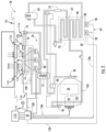
- the transport refrigeration systems 20 includes a vehicle 22, a container 24, and a transportation refrigeration unit (TRU) 26.
- the container 24 may be pulled by the vehicle 22. It is understood that embodiments described herein may be applied to shipping containers that are shipped by rail, sea, air, or any other suitable container, thus the vehicle may be a truck, train, boat, airplane, helicopter, etc.
- the container 24 may further include doors (not shown) at the rear wall 38, or any other wall.
- the walls 30, 32, 34, 36, 38 together define the boundaries of a cargo compartment 40.
- transport refrigeration systems 20 are used to transport and distribute cargo, such as, for example perishable goods and environmentally sensitive goods (herein referred to as perishable goods).
- the perishable goods may include but are not limited to fruits, vegetables, grains, beans, nuts, eggs, dairy, seed, flowers, meat, poultry, fish, ice, blood, pharmaceuticals, or any other suitable cargo requiring cold chain transport.
- the TRU 26 is associated with a container 24 to provide desired environmental parameters, such as, for example temperature, pressure, humidity, carbon dioxide, ethylene, ozone, light exposure, vibration exposure, and other conditions to the cargo compartment 40.
- desired environmental parameters such as, for example temperature, pressure, humidity, carbon dioxide, ethylene, ozone, light exposure, vibration exposure, and other conditions to the cargo compartment 40.
- the TRU 26 is a refrigeration system capable of providing a desired temperature and humidity range.
- the components of the TRU 26 includes a compressor 58, an electric compressor motor 60, a condenser 64 that may be air cooled, a condenser fan assembly 66, a receiver 68, a filter dryer 70, a heat exchanger 72, an expansion valve 74, an evaporator 76, an evaporator fan assembly 78, a suction modulation valve 80, and a controller 82 that may include a computer-based processor (e.g., microprocessor) and the like as will be described further herein. Operation of the TRU 26 may best be understood by starting at the compressor 58, where the suction gas (e.g., natural refrigerant, hydro-fluorocarbon (HFC) R-404a, HFC R-134a...
- the suction gas e.g., natural refrigerant, hydro-fluorocarbon (HFC) R-404a, HFC R-134a...
- the air flow across the condenser 64 may be facilitated by one or more fans 88 of the condenser fan assembly 66.
- the condenser fans 88 may be driven by respective condenser fan motors 90 of the fan assembly 66 that may be electric.
- the refrigerant gas within the tubes 86 condenses to a high pressure and high temperature liquid and flows to the receiver 68 that provides storage for excess liquid refrigerant during low temperature operation.
- the liquid refrigerant may pass through a sub-cooler heat exchanger 92 of the condenser 64, through the filter-dryer 70 that keeps the refrigerant clean and dry, then to the heat exchanger 72 that increases the refrigerant sub-cooling, and finally to the expansion valve 74.
- the liquid refrigerant passes through the orifices of the expansion valve 74, some of the liquid vaporizes into a gas (i.e., flash gas).
- a gas i.e., flash gas
- Return air from the refrigerated space i.e., cargo compartment 40
- the refrigerant flows through a plurality of tubes 94 of the evaporator 76, the remaining liquid refrigerant absorbs heat from the return air, and in so doing, is vaporized and thereby cools the return air.
- the evaporator fan assembly 78 includes one or more evaporator fans 96 that may be driven by respective fan motors 98 that may be electric. The air flow across the evaporator 76 is facilitated by the evaporator fans 96. From the evaporator 76, the refrigerant, in vapor form, may then flow through the suction modulation valve 80, and back to the compressor 58.
- the expansion valve 74 may be thermostatic or electrically adjustable. In an embodiment, as depicted, the expansion valve 74 is thermostatic.
- a thermostatic expansion valve bulb sensor 100 may be located proximate to an outlet of the evaporator tube 94.
- the bulb sensor 100 is intended to control the thermostatic expansion valve 74, thereby controlling refrigerant superheat at an outlet of the evaporator tube 94. It is further contemplated and understood that the above generally describes a single stage vapor compression system that may be used for HFCs such as R-404a and R-134a and natural refrigerants such as propane and ammonia. Other refrigerant systems may also be applied that use carbon dioxide (CO 2 ) refrigerant, and that may be a two-stage vapor compression system.
- the expansion valve 74 could be an electronic expansion valve. In this case the expansion valve is commanded to a selected position by the controller 82 based on the operating conditions of the vapor compression cycle and the demands of the system.
- a bypass valve may facilitate the flash gas of the refrigerant to bypass the evaporator 76. This will allow the evaporator coil to be filled with liquid and completely 'wetted' to improve heat transfer efficiency. With CO 2 refrigerant, this bypass flash gas may be re-introduced into a mid-stage of a two-stage compressor 58.
- the compressor 58 and the compressor motor 60 may be linked via an interconnecting drive shaft 102.
- the compressor 58, the compressor motor 60 and the drive shaft 102 may all be sealed within a common housing 104.
- the compressor 58 may be a single compressor.
- the single compressor may be a two-stage compressor, a scroll-type compressor or other compressors adapted to compress HFCs or natural refrigerants.
- the natural refrigerant may be CO 2 , propane, ammonia, or any other natural refrigerant that may include a global-warming potential (GWP) of about one (1).
- GWP global-warming potential
- FIG. 2 also illustrates airflow through the TRU 26 and the cargo compartment 40.
- Airflow is circulated into and through and out of the cargo compartment 40 of the container 24 by means of the TRU 26.
- a return airflow 134 flows into the TRU 26 from the cargo compartment 40 through a return air intake 136, and across the evaporator 76 via the fan 96, thus conditioning the return airflow 134 to a selected or predetermined temperature.
- the conditioned return airflow 134 now referred to as supply airflow 138, is supplied into the cargo compartment 40 of the container 24 through the refrigeration unit outlet 140, which in some embodiments is located near the top wall 30 of the container 24.
- the supply airflow 138 cools the perishable goods in the cargo compartment 40 of the container 24.
- the TRU 26 can further be operated in reverse to warm the container 24 when, for example, the outside temperature is very low.
- a temperature sensor 142 i.e., thermistor, thermocouples, RTD, and the like
- a sensor signal indicative of the return airflow temperature denoted RAT is operably connected via line 144 to the TRU controller 82 to facilitate control and operation of the TRU 26.
- a temperature sensor 146 is placed in the supply airflow 138, on the evaporator 76, at the refrigeration unit outlet 140 to monitor the temperature of the supply airflow 138 directed into the cargo compartment 40.
- a sensor signal indicative of the supply airflow temperature denoted SAT is operably connected via line 148 to the TRU controller 82 to facilitate control and operation of the TRU 26.
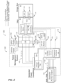
- the TRU 26 may include or be operably interfaced with a power supply interface shown generally as 120.
- the power supply interface 120 may include, interfaces to various power sources denoted generally as 122 and more specifically as follows herein for the TRU 26 and the components thereof.
- the power sources 122 may include, but not be limited to an energy storage device 152, generator 162, and grid power, 182.
- Each of the power sources 122 may be configured to selectively power the TRU 26 including compressor motor 60, the condenser fan motors 90, the evaporator fan motors 98, the controller 82, and other components 99 of the TRU 26 that may include various solenoids and/or sensors.
- the controller 82 through a series of data and command signals over various pathways 108 may, for example, control the application of power to the electric motors 60, 90, 98 as dictated by the cooling needs of the TRU 26.
- the TRU 26 may include an AC or DC architecture with selected components employing alternating current (AC), and others employing direct current (DC).
- the motors 60, 90, 98 may be configured as AC motors, while in other embodiments, the motors 60, 90, 98 may be configured as DC motors.
- the operation of the power sources 122 as they supply power to the TRU 26 is managed and monitored by power management system 124.
- the power management system 124 is configured to determine a status of various power sources 122, control their operation, and direct the power to and from the various power sources 122 and the like based on various requirements of the TRU 26.
- the TRU controller 82 receives various signals indicative of the operational state of the TRU 26 and determines the power requirements for the TRU system 26 accordingly and directs the power supply interface 120 and specifically the power management system 124 to direct power accordingly to address the requirements of the TRU 26.
- the TRU system 26 is controlled to a temperature setpoint value selected by the user.
- the TRU controller 82 monitors the RAT and optionally the SAT as measured by the temperature sensors 142 and 146 respectively.
- the (RAT-setpoint value) is between first threshold and second threshold, current requirement is limited (at known voltage) to achieve a mid-range power (e.g., ⁇ 50% power or something less than 100%). If the (RAT-setpoint value) is below second threshold, current is limited (at voltage) to achieve a minimum power (e.g., -20% power).
- the TRU controller 82 is configured to control the components in the TRU 26 as well as the components of the power supply interface 120 in accordance with operating needs of the transport refrigeration system 20.
- the TRU controller 82 is communicatively coupled to the power management system 124, DC/AC converter 156, battery management system 154 and the generator power converter 164 components of voltage regulator 166, current control circuit 167, frequency converter 168 and the generator 162.
- the TRU controller 82 using additional information from the BMS 154 and generator 162, provide instructions to affect the generator output to the power form required by the TRU 26.
- the TRU controller 82 provides instructions to manage the power flow via the power management system 124 depending upon the operational status of the various power sources (i.e. grid power 182, energy storage device 152 and generator 162) as coupled with the TRU 26 power demand.
- the TRU controller 82 knows, the power requirements for the TRU system, and thereby, what power is needed.
- the TRU controller 82 is also programmed to ascertain whether or not grid power (e.g., 182) is available or not. If the grid power is available and TRU is On and energy storage device 152 (e.g., battery) SOC indicates a full charge, grid power will satisfy TRU system 26 power demand.
- TRU power demand is satisfied as first priority and then DC/AC inverter 156 is be activated to provide necessary charging to energy storage device 152 as second priority.
- DC/AC inverter 156 will be activated to provide necessary charging current.
- all TRU power demand is satisfied by the energy storage system 150 via the energy storage device.
- TRU power demand is satisfied by both the generator 162 & energy storage system 150.
- the power management system 124 receives power from a generator 162 directly and/or via a generator power converter 164.
- the power management system 124 may be may be a stand-alone unit, integral with the generator power converter 164, and/or integral with the TRU 26.
- the generator 162 is axle or hub mounted configured to recover rotational energy when the transport refrigeration system 20 is in motion and convert that rotational energy to electrical energy, such as, for example, when the axle of the vehicle 22 is rotating due to acceleration, cruising, or braking.
- the generator 162 is configured to provide a first three phase AC power 163 comprising voltage Vi, an AC current Ii at a given frequency f 1 denoted by reference numeral 163.
- the generator 162 may be asynchronous or synchronous.
- the generator power converter 164 in one or more embodiments generates a second three phase AC power 165 including AC voltage V 2 , a second AC current I 2 at a selected frequency f 2 and is transmitted from the generator power converter 164 to the power management system 124 or otherwise as described herein.
- the TRU controller 82 identified the power requirements for the TRU 26 at least partially based on the RAT.
- the TRU controller 82 conveys the power requirements to the power management system 124 and/or the generator power converter 164 to convert the first three phase AC power 163 to the second three phase AC power 165 as necessary to satisfy the requirements of the TRU 26.
- the generator power converter 164 is an AC/AC converter and configured to receive the three phase AC power 163 (e.g., at AC voltage Vi, AC current Ii a frequency f 1 ), from the generator 162 and convert it to a second three phase AC power denoted 165 comprising the second three phase AC voltage V 2 , a second AC current I 2 at a selected frequency f 2 .
- the second three phase AC power 165 is transmitted from the generator power converter 164 to the power management system 124.
- the generator power converter 164 is configured to provide the second three phase AC power 165 based on the operating requirements of the TRU 26.
- the generator power converter 164 includes a voltage control function 166, a current control function 167, and frequency converter function 168, each configured to facilitate the conversion.
- the TRU controller 82 provides command signals denoted 169, 170, and 171 to a voltage control function 166, current control function 167, and frequency converter function 168 respectively.
- the command signals 169, 170, and 171 are generated by the TRU controller 82 based on the power consumption requirements of the TRU 26 as discussed further herein.
- the TRU controller 82 may receive status information as depicted by 172 regarding the generator 162, generator power converter 164, or the power management system 124 for mode selection and diagnostic purposes.
- the generator power converter 164 may be a stand-alone unit configured to be in close proximity to or even integral with the generator 162. In another embodiment, the generator power converter 164 may be integral with the power management system 124 and/or the TRU 26.
- the voltage control function 166 includes a voltage regulation function and is configured to monitor the output voltage from the generator 162 and maintains a constant voltage out of the voltage control function 166.
- the voltage control function 166 communicates status to the TRU Controller 82.
- the current control function 167 monitors and communicates to the TRU 26 the status of current draw from the generator 162. In an embodiment, the current may be limited depending on the power demands of the TRU 26.
- the frequency converter function 168 monitors the frequency of the three phase power 163 produced by the generator 162 and converts the three phase power 163 to the three phase power 165 exhibiting the desired frequency as determined by the voltage control function 166 and the TRU controller 82, for supply to the power management system 124 and ultimately the TRU 26.
- the communications may be over standard communication interfaces such as CAN, RS-485, and the like.
- the communications may be wired or wireless.
- one of the power sources 122 may include, but not be limited to an energy storage system 150 operably coupled to the power management system 124.
- another power source 122 that the power management system 124 receives power from is the generator 162, whether directly and/or via a generator power converter 164.
- the grid power source 182 provides three phase AC power to the power management system 124 under selected conditions.
- the energy storage system 150 transmits three phase power 157 to and receives power from the power management system 124.
- the energy storage system 150 may include, but not be limited to the energy storage device 152, and AC/DC converter 156 and a battery management system 154.
- the power management system 124 provides three phase AC power 157 to an AC/DC converter 156 to formulate a DC voltage and current to charge and store energy on the energy storage device 152.
- the energy storage device 152 supplies DC voltage and current to the AC/DC converter 156 operating as a DC/AC converter to supply a three phase AC power 157 for powering the TRU 26.
- the battery management system 154 monitors the performance of the energy storage device 152. For example, monitoring the state of charge of the energy storage device 152, a state of health of the energy storage device 152, and a temperature of the energy storage device 152.
- the energy storage device 152 may include a battery system (e.g., a battery or bank of batteries), fuel cells, flow battery, and others devices capable of storing and outputting electric energy that may be direct current (DC).
- the energy storage device 152 may include a battery system, which may employ multiple batteries organized into battery banks through which cooling air may flow for battery temperature control, as described in U. S. patent application Ser. No. 62/616,077, filed January 11, 2018 .
- the battery system may have a voltage potential within a range of about two-hundred volts (200V) to about six-hundred volts (600V).
- the higher the voltage the greater is the sustainability of electric power which is preferred.
- the higher the voltage the greater is the size and weight of, for example, batteries in an energy storage device 152, which is not preferred when transporting cargo.
- the energy storage device 152 is a battery, then in order to increase either voltage and/or current, the batteries need to be connected in series or parallel depending upon electrical needs.
- the energy storage device 152 may be contained within the structure 27 of the TRU 26. In an embodiment, the energy storage device 152 is located with the TRU 26, however, other configurations are possible. In another embodiment, the energy storage device 152 may be located with the container 24 such as, for example, underneath the cargo compartment 40.
- the AC/DC converter 156 may be located with the container 24 such as, for example, underneath the cargo compartment 40, however, in some embodiments it may be desirable to have the AC/DC converter 156 in close proximity to the power management system 124 and/or the TRU 26 and TRU controller 82. It will be appreciated that in one or more embodiments, while particular locations are described with respect to connection and placement of selected components including the energy storage device 152 and/or AC/DC converter 156, such descriptions are merely illustrative and are not intended to be limiting. Varied location, arrangement and configuration of components is possible and within the scope of the disclosure.
- the battery management system 154 and AC/DC converter 156 are operably connected to and interface with the TRU controller 82.
- the TRU controller 82 receives information regarding the status of energy storage system 150, including the energy storage device 152 to provide control inputs to the AC/DC converter 156 to monitor the energy storage device 152, control charge and discharge rates for the energy storage device 152 and the like.
- the power supply interface 120 may include, interfaces to various power sources 122 managed and monitored by power management system 124.
- the power management system 124 manages and determines electrical power flows in the power supply interface 120 based upon the operational needs of the TRU 26 and the capabilities of the components in the power supply interface 120, (e.g., generator 162, converter 164, energy storage device 152, and the like.
- the power management system 124 is configured to determine a status of various power sources 122, control their operation, and direct the power to and from the various power sources 122 and the like based on various requirements of the TRU 26.
- the power management system 124 there are five primary power flows managed by the power management system 124.
- the power flows will be transferred through different paths based on the requirements placed on the power management system 124 and particular configuration of the power supply interface 120.
- the power management system 124 operates as a central power bus to connect various power sources 122 together to supply the power needs of the TRU 26.
- the power management system 124 controls switching, directing, or redirecting power to/from the five power flows as needed to satisfy the power requirements of the TRU 26. Switching, directing, and redirecting may readily be accomplished by employing a bus control switching device 126 of the power management system 124.
- the bus control switching device 126 may include, but not be limited to, electromechanical and solid state semiconductor switching devices including relays, contactors, solid state contactors as well as semiconductor switching devices such as transistors, FETs, MOSFETS, IGBT's, thyristors, SCR's, and the like.
- the voltages and frequencies of the power whether supplied by the grid power supply 182, generator 162, generator converter 164, or the AC/DC converter 156 of the energy storage system 150 need to be synchronized to provide a common power source to be supplied to the TRU 26 and/or charge the energy storage device 152. Current draw will be determined by the TRU 26 and the need to charge the energy storage device 152.
- the generator power converter 164 output (the second three phase AC power 165) and/or grid power from the grid power source 182 and/or power directed to/from the energy storage system 150 is supplied to the bus control switching device 126 in an overlapping or break-before-make condition as determined by the bus control switching device 126 of the power management system.
- the AC/DC converter 156 when operating as a DC to AC converter synchronizes the voltage and frequency of the three phase power (e.g., 157) generated via the energy storage system 150 with the power connected bus control switching device 126 in order to transfer power from the energy storage device 152 to the power management system 124 (an thereby the TRU 26) as needed.
- grid power from the grid power source 182 provided to the power management system 124 is directed by the bus control switching device 126 once connected and the AC/DC converter 156 monitor the bus voltage and frequency to determine if the above parameters are equal before connectivity is permitted. This will allow minimum disruption of the power bus system. In other words, anytime two or more power sources are available, the bus control switching device, and the AC/DC convert 156 ensure that power is matched and synchronized to enable connectivity.
- the power bus control device 126 communicates to the TRU controller 82 to determine status of flows connected.
- the power management system 124, and or the TRU controller 82 provides visual indications of which source (e.g., grid power source 182, generator 162 or energy storage system 150) is selected and operating on the bus control switching device 126.
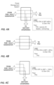
- FIGS. 4A-4H each providing a simplified diagram depicting each of the eight identified power flows combinations.
- FIGS. 4A-4C depict power flows for power supplied from the generator 162 and/or generator power converter 164 (e.g., second three phase AC power).
- the logic employed by the TRU controller 82 for directing the power in the power management system 124 determines if the TRU 26 is operating. If so, and the energy storage system 150 indicates that the energy storage device 120 is exhibiting a charge state that is less than a selected threshold, then the power management system 124 directs power to both the TRU 26 and the energy storage system 150 for recharging the energy storage device 152.
- priority is given to satisfying the power requirements of the TRU 26. Any remaining power may be directed to the recharging application for the energy storage system 150. It should be appreciated that while particular threshold of 80% is disclosed and employed for the described embodiments, such values and description are merely illustrative. Other values and applications for the thresholds are possible.
- FIG 4B the figure depicts a second instance for power flows for power supplied from the generator 162 and/or generator power converter 164.
- the power management system 124 directs power to only the TRU 26, (as the and the energy storage system 150 does not yet require recharging).
- FIG 4C a third power flow governed by the power management system 124 for power supplied from the generator 162 and/or generator power converter 164.
- the logic employed by the TRU controller 82 for directing the power in the power management system 124 addresses an instance when the TRU 26 is inoperative, and the energy storage system 150 indicates that the energy storage device 152 is exhibiting a state of charge that is less than a selected threshold (in this instance 100%, though other thresholds are possible).
- the power management system 124 directs power to only to the energy storage system 150 for recharging the energy storage device 152.
- priority is given to satisfying the power requirements of energy storage system 150 and secondarily to providing power to the TRU 26.
- FIGS. 4D-4F depict power flows for power supplied from the grid power source 182.
- the logic employed by the TRU controller 82 for directing the power from the grid power source 182 in the power management system 124 determines if the TRU 26 is operating and the generator 162 (or the generator power converter 164) is inoperative. If so, and the energy storage system 150 indicates that the energy storage device 152 is exhibiting a charge state that is less than a selected threshold, then the power management system 124 directs power to both the TRU 26 and the energy storage system 150 for recharging the energy storage device 152. In an embodiment, once again, priority is given to satisfying the power requirements of the TRU 26.
- any remaining power may be directed to the recharging application for the energy storage system 150. It should be appreciated that while particular threshold of 80% is disclosed and employed for the described embodiments, such values and description are merely illustrative. Other values and applications for the thresholds are possible.
- FIG 4E the figure depicts a second instance for power flows for power supplied from the grid power source 182 when the generator 162 is inoperative.
- the power management system directs power to only the TRU 26, (as the energy storage system 150 does not yet require recharging).
- FIG 4F a third power flow governed by the power management system 124 for power supplied from the grid power source 182 when the generator 162 is inoperative.
- the logic employed by the TRU controller 82 for directing the power in the power management system 124 addresses an instance when the TRU 26 is also inoperative, and the energy storage system 150 indicates that the energy storage device 152 is exhibiting a state of charge that is less than a selected threshold (in this instance 100%, though other thresholds are possible).
- the power management system 124 directs power to only to the energy storage system 150 for recharging the energy storage device 152. In an embodiment, priority is given to satisfying the power requirements of energy storage system 150.
- FIGS. 4G and 4H depict power flows for power supplied to the TRU 26 under selected conditions for operating from the energy storage system 150 as well.
- power flows to the TRU 26 are provided from the generator 162 and/or generator power converter 164 (e.g., second three phase AC power 165) as well as from the energy storage system 150.
- the logic employed by the TRU controller 82 for directing the power in the power management system 124 determines if the TRU 26 is operating.
- the power management system 124 directs power from both the generator 162 (or generator power converter 164) and the energy storage system 150 is directed to the TRU 26.
- a threshold of 10 percent is employed for the state of charge of the energy storage device 152.
- power is provided by the energy storage system 150 and thereby discharging the energy storage device 152.
- priority is given to satisfying the power requirements of the TRU 26. This embodiment may be employed under conditions where the output power of the generator 162 and/or generator power converter 164 is less that that needed to operate the TRU 26.
- threshold of 10% is disclosed and employed for the described embodiments, such values and description are merely illustrative. Other values and applications for the thresholds are possible. For example, in some instances it may be desirable prioritize operation of the TRU 26 such that fully draining the energy storage device 152 is acceptable. Likewise, in other embodiments, it may be desirable to modify the function or curtail the operation of the TRU 26 to avoid excessively discharging the energy storage device 152.
- the figure depicts a second instance for power flows from the energy storage system 150 alone.
- the power management system 124 directs power to the TRU 26.
- a threshold of 10 percent is employed for the state of charge of the energy storage device 152.
- power is provided by the energy storage system 150 and thereby discharging the energy storage device 152.
- priority is given to satisfying the power requirements of the TRU 26.
- this embodiment may be employed under conditions where the output power of the generator 162 and/or generator power converter 164 is less that that needed to operate the TRU 26.
- threshold of 10% is disclosed and employed for the described embodiments, such values and description are merely illustrative. Other values and applications for the thresholds are possible. For example, in some instances it may be desirable prioritize operation of the TRU 26 such that fully draining the energy storage device 152 is acceptable. Likewise, in other embodiments, it may be desirable to modify the function or curtail the operation of the TRU to avoid excessively discharging the energy storage device 152.
- the power supply interface 120 is configured such that, in selected modes of operation power is directed to the TRU 26 from the vehicle 22.
- TRU power could be drawn from the power system of the tractor or truck. (i.e. tie into the energy storage device or generator of the tractor/truck).
- the described embodiments while generally referring to the generator 162 being installed on the trailer portion of the vehicle 22, such description is merely illustrative. In another embodiment, the generator 162 or another generator could be installed at a hub or axle of the tractor portion of the vehicle 22 without loss of generality and still be fully applicable to the described embodiments.
- the tractor/truck power may be routed to the power management system through a grid plug 185. Alternately connectable between the grid power source 182 and the vehicle power. For example, in operation, when vehicle 22 trailer is in operation, for example, on delivery, grid plug 185 would be plugged into the tractor/trailer's electric PTO and act as mobile grid source.
- the TRU controller 82 would be programmed to determine if the grid plug is active and if so, to pull power (or supplement generator power) only if energy storage device SOC is below threshold as alternative to modify the function or curtail the operation of the TRU system 26.
- the TRU 26 may further include a renewable power source 110 ( FIG. 1 ) configured to recharge the batteries of the energy storage device 152.
- a renewable power source 110 may be solar panels mounted, for example, to the outside of the top wall 30 of the container 24 (also see FIG. 1 ).
- the renewable power source 110 could generate all or a portion of the needed low voltage DC power for the TRU controller 82.
- Benefits of the present invention when compared to more traditional systems include no fuel carriage, fuel system and fuel consumption, and a refrigeration unit that emits less noise and no combustion byproducts. Yet further, the present invention includes an energy storage device that is conveniently and efficiently recharged to meet the power demands of the refrigeration unit.
- embodiments can be in the form of processor-implemented processes and devices for practicing those processes, such as a processor.
- Embodiments can also be in the form of computer program code containing instructions embodied in tangible media, such as network cloud storage, SD cards, flash drives, floppy diskettes, CD ROMs, hard drives, or any other computer-readable storage medium, wherein, when the computer program code is loaded into and executed by a computer, the computer becomes a device for practicing the embodiments.
- Embodiments can also be in the form of computer program code, for example, whether stored in a storage medium, loaded into and/or executed by a computer, or transmitted over some transmission medium, loaded into and/or executed by a computer, or transmitted over some transmission medium, such as over electrical wiring or cabling, through fiber optics, or via electromagnetic radiation, wherein, when the computer program code is loaded into an executed by a computer, the computer becomes a device for practicing the embodiments.
- the computer program code segments configure the microprocessor to create specific logic circuits.
Landscapes
- Engineering & Computer Science (AREA)
- Mechanical Engineering (AREA)
- Physics & Mathematics (AREA)
- Thermal Sciences (AREA)
- Power Engineering (AREA)
- Transportation (AREA)
- Combustion & Propulsion (AREA)
- Chemical & Material Sciences (AREA)
- General Engineering & Computer Science (AREA)
- Life Sciences & Earth Sciences (AREA)
- Sustainable Development (AREA)
- Sustainable Energy (AREA)
- Supply And Distribution Of Alternating Current (AREA)
- Devices That Are Associated With Refrigeration Equipment (AREA)
Claims (15)
- Transportkühlsystem (20), umfassend:ein Fahrzeug (22);einen Behälter (24);eine Transportkühleinheit (transport refrigeration unit - TRU) (26), umfassend:einen Kompressor (58), der dazu konfiguriert ist, ein Kältemittel zu komprimieren, wobei der Kompressor (58) einen Kompressormotor (60) aufweist, der dazu konfiguriert ist, den Kompressor (58) anzutreiben;einen Verdampferwärmetauscher (76), der an den Kompressor (58) wirkgekoppelt ist;ein Verdampfergebläse (96), das dazu konfiguriert ist, einen Rückluftstrom (134) von einem Rücklufteinlass (136) bereitzustellen und den Rückluftstrom (134) über den Verdampferwärmetauscher (76) strömen zu lassen;einen Rücklufttemperatur-RAT-Sensor (142), der in dem Rückluftstrom (134) angeordnet und dazu konfiguriert ist, die Temperatur des Rückluftstroms (return airflow temperature - RAT) (134) zu messen; undeine TRU-Steuerung (82), die mit dem RAT-Sensor (142) in Wirkverbindung steht und dazu konfiguriert ist, einen Prozess zum Bestimmen eines Wechselstrom(AC)-Leistungsbedarfs für die TRU (26) zumindest basierend auf der RAT auszuführen; undein Leistungsverwaltungssystem (124), wobei das Leistungsverwaltungssystem (124) zumindest teilweise basierend auf dem Wechselstrom-Leistungsbedarf Leistung an die TRU (26) leitet, und dadurch gekennzeichnet, dass das Leistungsverwaltungssystem (124) dazu konfiguriert ist, mindestens eines von Folgenden zu empfangen:eine erste Dreiphasen-Wechselstromleistung (163) von einem Wechselstromgenerator (162), der an eine Achse oder Radnabe eines Traktor- oder Anhängerabschnitts des Fahrzeugs wirkgekoppelt ist; undeine zweiten Dreiphasen-Wechselstromleistung (165) von einem Generator-Leistungswandler (164), der die erste Dreiphasen-Wechselstromleistung (163) umwandelt.
- Transportkältesystem nach Anspruch 1, wobei der Wechselstromgenerator (162) dazu konfiguriert ist, Rotationsenergie von der Achse oder Radnabe zurückzugewinnen, wenn das Transportkältesystem (20) in Bewegung ist, und die Rotationsenergie in elektrische Energie umzuwandeln.
- Transportkältesystem nach Anspruch 1 oder Anspruch 2, wobei der Generator-Leistungswandler (164) einen AC/AC-Wandler beinhaltet und die erste Dreiphasen-Wechselstromleistung (163) eine erste Wechselstrom-Spannung (V1) und einen ersten Wechselstrom-Strom (I1) mit einer ersten Frequenz (f1) aufweist und die zweite Dreiphasen-Wechselstromleistung eine zweite Wechselstrom-Spannung (V2) und einen zweiten Wechselstrom-Strom (165) (I2) mit einer zweiten Frequenz (f2) aufweist.
- Transportkältesystem nach Anspruch 3, wobei der Generator-Leistungswandler (164) die zweite Dreiphasen-Wechselstromleistung (165) zumindest teilweise basierend auf dem Wechselstrom-Leistungsbedarf erzeugt.
- Transportkühlsystem nach einem der vorhergehenden Ansprüche, ferner beinhaltend ein Energiespeichersystem (150), das dazu konfiguriert ist, eine dritte Dreiphasen-Wechselstromleistung (157) an dem Leistungsverwaltungssystem (124) bereitzustellen oder von diesem zu empfangen.
- Transportkältesystem nach Anspruch 5, wobei der Generator-Leistungswandler (164) mit der TRU-Steuerung (82) in Wirkverbindung steht, wobei der Generator-Leistungswandler (164) eine Spannungssteuerfunktion (166), eine Stromsteuerfunktion (167) und eine Frequenzsteuerfunktion (168) beinhaltet, wobei mindestens die Spannungssteuerfunktion (166) zumindest teilweise auf den Wechselstrom-Leistungsbedarf reagiert.
- Transportkühlsystem nach Anspruch 5 oder Anspruch 6, wobei das Energiespeichersystem (150) eine Energiespeichervorrichtung (152) und mindestens einen von einem DC/AC-Wandler (156), der dazu konfiguriert ist, die dritte Dreiphasen-Wechselstromleistung (157) zumindest teilweise basierend auf dem Wechselstrom-Leistungsbedarf an dem Leistungsverwaltungssystem (150) bereitzustellen, und einem AC/DC-Wandler (156), der dazu konfiguriert ist, mindestens einen Teil der Dreiphasen-Wechselstromleistung (157) in Gleichstromleistung umzuwandeln, um die Energiespeichervorrichtung (152) zu versorgen, umfasst.
- Transportkühlsystem nach Anspruch 7, ferner beinhaltend ein Batterieverwaltungssystem (154), das mit der TRU-Steuerung (82) in Wirkverbindung steht und dazu konfiguriert ist, mindestens einen Ladezustand der Energiespeichervorrichtung (152) zu überwachen.
- Transportkältesystem nach Anspruch 8, wobei der DC/AC-Wandler (156) und der AC/DC-Wandler (156) integriert sind und wobei der DC/AC-Wandler (156) und der AC/DC-Wandler (156) mit der TRU-Steuerung (82) in Wirkverbindung stehen und die TRU-Steuerung (82) dazu konfiguriert ist, Leistungsflüsse zu dem Leistungsverwaltungssystem (124) und von dem Leistungsverwaltungssystem (124) zumindest teilweise basierend auf mindestens einem von dem Wechselstrom-Leistungsbedarf und dem Ladezustand der Energiespeichervorrichtung (152) zu leiten.
- Transportkältesystem nach einem der Ansprüche 1-4, wobei das Leistungsverwaltungssystem (124) dazu konfiguriert ist, mindestens eine von der ersten Dreiphasen-Wechselstromleistung (163) von dem Wechselstromgenerator (162) und der zweiten Dreiphasen-Wechselstromleistung (165) von dem Generator-Leistungswandler (164), eine dritte Dreiphasen-Wechselstromleistung (157) von einem Energiespeichersystem (150) und eine Dreiphasen-Netzleistung von einer Netzleistungsquelle (182) zu empfangen, und wobei das Leistungsverwaltungssystem (124) dazu konfiguriert ist, eine ausgewählte Dreiphasen-Wechselstromleistung an mindestens einem von der TRU (26) und dem Energiespeichersystem (150) bereitzustellen.
- Transportkühlsystem nach einem der Ansprüche 1-4, wobei das Leistungsverwaltungssystem (124) eine Leistungssteuerungs-Schaltvorrichtung (126) beinhaltet, wobei die Leistungssteuerungs-Schaltvorrichtung (126) auf die TRU-Steuerung (82) reagiert und dazu konfiguriert ist, eine Vielzahl von Leistungsflüssen in dem Transportkühlsystem (20) zu leiten, wobei die Vielzahl von Leistungsflüssen zumindest teilweise auf mindestens einem von dem Wechselstrom-Leistungsbedarf und einem Ladezustand einer Energiespeichervorrichtung (152) eines Energiespeichersystems (154) basiert.
- Transportkältesystem nach Anspruch 11, wobei ein erster Teil der Leistungsflüsse der Vielzahl von Leistungsflüssen Folgendes umfasst:Empfangen einer von der ersten Dreiphasen-Wechselstromleistung (163) von dem Wechselstromgenerator (162) und der zweiten Dreiphasen-Wechselstromleistung (165) von dem Generator-Leistungswandler (164), wenn der Wechselstromgenerator (162) in Betrieb ist; undLeiten mindestens eines Teils mindestens einer von der ersten Dreiphasen-Wechselstromleistung (163) und der zweiten Dreiphasen-Wechselstromleistung (165) an die TRU (26) und das Energiespeichersystem (150), wenn die TRU (26) in Betrieb ist und die Energiespeichervorrichtung (152) des Energiespeichersystems (150) einen Ladezustand aufweist, der unter einem ausgewählten Schwellenwert liegt; oderLeiten mindestens eines Teils mindestens einer von der ersten Dreiphasen-Wechselstromleistung (163) und der zweiten Dreiphasen-Wechselstromleistung (165) an die TRU (26), wenn die TRU (26) in Betrieb ist und die Energiespeichervorrichtung (152) des Energiespeichersystems (150) einen Ladezustand aufweist, der über dem ausgewählten Schwellenwert liegt oder etwa gleich diesem ist; oderLeiten mindestens eines Teils der ersten Dreiphasen-Wechselstromleistung und der zweiten Dreiphasen-Wechselstromleistung an das Energiespeichersystem (150), wenn die TRU (26) nicht in Betrieb ist und die Energiespeichervorrichtung (152) des Energiespeichersystems einen Ladezustand aufweist, der unter einem zweiten ausgewählten Schwellenwert liegt.
- Transportkältesystem nach Anspruch 11 oder Anspruch 12, wobei ein zweiter Teil der Leistungsflüsse der Vielzahl von Leistungsflüssen Folgendes umfasst:Empfangen einer Netz-Dreiphasen-Wechselstromleistung von der Netzleistungsquelle (182); undLeiten mindestens eines Teils der Netz-Dreiphasen-Wechselstromleistung an die TRU (26) und das Energiespeichersystem (150), wenn die TRU (26) in Betrieb ist und die Energiespeichervorrichtung (152) des Energiespeichersystems (150) einen Ladezustand aufweist, der unter einem ausgewählten Schwellenwert liegt; oderLeiten mindestens eines Teils der Netz-Dreiphasen-Wechselstromleistung an die TRU (26), wenn die TRU (26) in Betrieb ist und die Energiespeichervorrichtung (152) des Energiespeichersystems (150) einen Ladezustand aufweist, der über dem ausgewählten Schwellenwert liegt oder etwa gleich diesem ist; oderLeiten mindestens eines Teils der Netz-Dreiphasen-Wechselstromleistung an das Energiespeichersystem (150), wenn die TRU (26) nicht in Betrieb ist und die Energiespeichervorrichtung (152) des Energiespeichersystems (150) einen Ladezustand aufweist, der unter einem zweiten ausgewählten Schwellenwert liegt.
- Transportkältesystem nach einem der Ansprüche 11 bis 13, wobei ein dritter Teil der Leistungsflüsse der Vielzahl von Leistungsflüssen Folgendes umfasst:Empfangen einer dritten Dreiphasen-Wechselstromleistung (157) von dem Energiespeichersystem (150) und der Dreiphasen-Wechselstromleistung (163, 165) von mindestens einem von dem Wechselstromgenerator (162) oder dem Generator-Leistungswandler (164), wenn der Wechselstromgenerator (162) oder der Generator-Leistungswandler (164) in Betrieb ist;Synchronisieren und Kombinieren der dritten Dreiphasen-Wechselstromleistung (157) von dem Energiespeichersystem (150) und der mindestens einen von der ersten Dreiphasen-Wechselstromleistung (163) und der zweiten Dreiphasen-Wechselstromleistung (165); undLeiten der kombinierten Dreiphasen-Wechselstromleistung an die TRU (26), wenn die TRU (26) in Betrieb ist und die Energiespeichervorrichtung (152) des Energiespeichersystems (150) einen Ladezustand aufweist, der über einem weiteren ausgewählten Schwellenwert liegt oder etwa gleich diesem ist.
- Verfahren zum Erzeugen und Leiten von Leistung zu einer Transportkälteeinheit (TRU) (26) eines Transportkältesystems (20), wobei die TRU (26) Folgendes aufweist: einen Kompressor (58), der dazu konfiguriert ist, ein Kältemittel zu komprimieren, einen Verdampferwärmetauscher (76), der an den Kompressor (58) wirkgekoppelt ist;ein Verdampfergebläse (96), das dazu konfiguriert ist, einen Rückluftstrom (134) von einem Rücklufteinlass (136) bereitzustellen und den Rückluftstrom (134) über den Verdampferwärmetauscher (76) strömen zu lassen;einen Rücklufttemperatur-RAT-Sensor (142), der in dem Rückluftstrom (134) angeordnet und dazu konfiguriert ist, die Temperatur des Rückluftstroms (RAT) (134) zu messen;und eine TRU-Steuerung (82), wobei das Verfahren Folgendes umfasst:Bestimmen eines Wechselstrom-Leistungsbedarfs für die TRU (26) zumindest teilweise basierend auf der RAT;Bereitstellen mindestens einer von einer ersten Dreiphasen-Wechselstromleistung (163) von einem Wechselstromgenerator (162), der an eine Achse oder Radnabe eines Traktor- oder Anhängerabschnitts eines Fahrzeugs der Transportkältesystem (20) wirkgekoppelt ist, und einer zweiten Dreiphasen-Wechselstromleistung (165) von einem Generator-Leistungswandler (164), der die erste Dreiphasen-Wechselstromleistung (163) umwandelt;Empfangen mindestens einer von der ersten Dreiphasen-Wechselstromleistung (163) und der zweiten Dreiphasen-Wechselstromleistung (165) durch ein Leistungsverwaltungssystem (124) und Leiten von Leistung an die TRU (26) zumindest teilweise basierend auf dem Wechselstrom-Leistungsbedarf.
Applications Claiming Priority (2)
| Application Number | Priority Date | Filing Date | Title |
|---|---|---|---|
| US201862738664P | 2018-09-28 | 2018-09-28 | |
| PCT/US2019/052395 WO2020068646A1 (en) | 2018-09-28 | 2019-09-23 | Transportation refrigeration unit with external ac generator power source |
Publications (2)
| Publication Number | Publication Date |
|---|---|
| EP3856550A1 EP3856550A1 (de) | 2021-08-04 |
| EP3856550B1 true EP3856550B1 (de) | 2024-08-14 |
Family
ID=68165723
Family Applications (1)
| Application Number | Title | Priority Date | Filing Date |
|---|---|---|---|
| EP19783782.6A Active EP3856550B1 (de) | 2018-09-28 | 2019-09-23 | Transportkühleinheit mit externer wechselstromgeneratorstromquelle |
Country Status (4)
| Country | Link |
|---|---|
| US (1) | US11932076B2 (de) |
| EP (1) | EP3856550B1 (de) |
| CN (1) | CN112334342B (de) |
| WO (1) | WO2020068646A1 (de) |
Cited By (1)
| Publication number | Priority date | Publication date | Assignee | Title |
|---|---|---|---|---|
| EP4707003A1 (de) * | 2024-08-30 | 2026-03-11 | Carrier Corporation | Transportkühlsystem mit mehreren leistungsmodi |
Families Citing this family (35)
| Publication number | Priority date | Publication date | Assignee | Title |
|---|---|---|---|---|
| US11872867B2 (en) * | 2014-02-28 | 2024-01-16 | Enow Systems Llc | Tractor trailer refrigeration unit |
| EP3626489A1 (de) | 2018-09-19 | 2020-03-25 | Thermo King Corporation | Verfahren und systeme zur energieverwaltung einer klimaanlage für transportfahrzeuge |
| EP3626490A1 (de) | 2018-09-19 | 2020-03-25 | Thermo King Corporation | Verfahren und systeme zur leistungs- und lastverwaltung einer klimaanlage für den transport |
| US11034213B2 (en) | 2018-09-29 | 2021-06-15 | Thermo King Corporation | Methods and systems for monitoring and displaying energy use and energy cost of a transport vehicle climate control system or a fleet of transport vehicle climate control systems |
| US11273684B2 (en) | 2018-09-29 | 2022-03-15 | Thermo King Corporation | Methods and systems for autonomous climate control optimization of a transport vehicle |
| US10926610B2 (en) | 2018-10-31 | 2021-02-23 | Thermo King Corporation | Methods and systems for controlling a mild hybrid system that powers a transport climate control system |
| US10870333B2 (en) | 2018-10-31 | 2020-12-22 | Thermo King Corporation | Reconfigurable utility power input with passive voltage booster |
| US11059352B2 (en) | 2018-10-31 | 2021-07-13 | Thermo King Corporation | Methods and systems for augmenting a vehicle powered transport climate control system |
| US10875497B2 (en) | 2018-10-31 | 2020-12-29 | Thermo King Corporation | Drive off protection system and method for preventing drive off |
| US11022451B2 (en) | 2018-11-01 | 2021-06-01 | Thermo King Corporation | Methods and systems for generation and utilization of supplemental stored energy for use in transport climate control |
| US11554638B2 (en) | 2018-12-28 | 2023-01-17 | Thermo King Llc | Methods and systems for preserving autonomous operation of a transport climate control system |
| US11993131B2 (en) | 2018-12-31 | 2024-05-28 | Thermo King Llc | Methods and systems for providing feedback for a transport climate control system |
| EP3906175A1 (de) | 2018-12-31 | 2021-11-10 | Thermo King Corporation | Verfahren und systeme zur bereitstellung von prädiktiver energieverbrauchsrückkopplung zur speisung eines transportklimaregelungssystems unter verwendung externer daten |
| US11072321B2 (en) | 2018-12-31 | 2021-07-27 | Thermo King Corporation | Systems and methods for smart load shedding of a transport vehicle while in transit |
| US12072193B2 (en) | 2018-12-31 | 2024-08-27 | Thermo King Llc | Methods and systems for notifying and mitigating a suboptimal event occurring in a transport climate control system |
| EP3906173B1 (de) | 2018-12-31 | 2024-05-22 | Thermo King LLC | Verfahren und systemen mit feedback eines prädiktiven abgeschätzten energieverbrauch es zur steuerung eines klimaaggregates für eine transportvorrichtung |
| ES2965029T3 (es) | 2019-06-28 | 2024-04-10 | Thermo King Llc | Vehículo climatizado, equipo de control climático para el transporte, método de readaptación de un vehículo y método de funcionamiento |
| EP3790157A1 (de) | 2019-09-09 | 2021-03-10 | Thermo King Corporation | Optimierte energieverteilung für transportklimatisierungssysteme zwischen einer oder mehreren stationen der elektrischen versorgungsanlagen |
| US11420495B2 (en) | 2019-09-09 | 2022-08-23 | Thermo King Corporation | Interface system for connecting a vehicle and a transport climate control system |
| US11458802B2 (en) | 2019-09-09 | 2022-10-04 | Thermo King Corporation | Optimized power management for a transport climate control energy source |
| ES2992855T3 (en) | 2019-09-09 | 2024-12-19 | Thermo King Llc | Prioritized power delivery for facilitating transport climate control |
| US10985511B2 (en) | 2019-09-09 | 2021-04-20 | Thermo King Corporation | Optimized power cord for transferring power to a transport climate control system |
| US11135894B2 (en) | 2019-09-09 | 2021-10-05 | Thermo King Corporation | System and method for managing power and efficiently sourcing a variable voltage for a transport climate control system |
| US11214118B2 (en) | 2019-09-09 | 2022-01-04 | Thermo King Corporation | Demand-side power distribution management for a plurality of transport climate control systems |
| US11203262B2 (en) | 2019-09-09 | 2021-12-21 | Thermo King Corporation | Transport climate control system with an accessory power distribution unit for managing transport climate control loads |
| US11376922B2 (en) | 2019-09-09 | 2022-07-05 | Thermo King Corporation | Transport climate control system with a self-configuring matrix power converter |
| US11489431B2 (en) | 2019-12-30 | 2022-11-01 | Thermo King Corporation | Transport climate control system power architecture |
| EP3904141B1 (de) * | 2020-04-29 | 2025-08-06 | Carrier Corporation | Kühlaggregat mit vorkühlung für batterieelektrische fahrzeuge |
| WO2021219809A1 (en) * | 2020-04-30 | 2021-11-04 | Dipp-R Ab | A power supply system for an electric vehicle and a cargo box |
| DE102020213312A1 (de) | 2020-10-22 | 2022-04-28 | Zf Friedrichshafen Ag | Vorrichtung zum Bereitstellen einer Betriebsleistung für einen Zusatzantrieb für ein Elektrofahrzeug und Verfahren zum Wandeln einer Betriebsspannung |
| EP4036592B1 (de) * | 2021-01-26 | 2025-01-01 | Carrier Corporation | Batteriegesundheitsselbsttestprotokoll |
| GB2607875A (en) * | 2021-06-09 | 2022-12-21 | Renewable Innovations And Solutions Ltd | Power system for supplying electrical energy to a refrigerator of a refrigerated vehicle and associated control system and method |
| EP4206021A1 (de) * | 2022-01-04 | 2023-07-05 | Carrier Corporation | Stromquellenanpassungsvorrichtung für eine transportkühleinheit |
| US12355339B2 (en) * | 2022-07-18 | 2025-07-08 | Carrier Corporation | Hybrid power system for transport refrigeration systems |
| US20250027999A1 (en) * | 2023-07-21 | 2025-01-23 | Thermo King Llc | Adaptive charge control for transport climate control applications |
Family Cites Families (49)
| Publication number | Priority date | Publication date | Assignee | Title |
|---|---|---|---|---|
| US1004664A (en) | 1906-12-05 | 1911-10-03 | Expl Des Procedes Westinghouse Leblanc Sa | Condenser. |
| US3866433A (en) | 1973-09-12 | 1975-02-18 | Jeffreys George C | Auxiliary refrigeration power means |
| US4761577A (en) | 1987-07-02 | 1988-08-02 | Thomas Stephen E | Wheel-mounted electrical power generator |
| JPH079011Y2 (ja) | 1989-04-24 | 1995-03-06 | 澤藤電機株式会社 | 車両用冷凍装置 |
| US5265435A (en) | 1992-12-31 | 1993-11-30 | Phyllis M. Morefield | Vehicle refrigeration system |
| JP2000121202A (ja) * | 1998-10-12 | 2000-04-28 | Isuzu Motors Ltd | 冷凍・冷蔵車 |
| JP2002081825A (ja) * | 2000-09-01 | 2002-03-22 | Denso Corp | 冷凍冷蔵庫 |
| US6725713B2 (en) | 2002-05-10 | 2004-04-27 | Michelin & Recherche Et Technique S.A. | System for generating electric power from a rotating tire's mechanical energy using reinforced piezoelectric materials |
| EP1587696B1 (de) | 2002-12-20 | 2007-02-28 | PEARMAN, Kevin Patrick Austin | Radmontierter energieerzeuger |
| US7259469B2 (en) | 2003-07-31 | 2007-08-21 | Scs Frigette Inc. | Vehicle auxiliary power unit, assembly, and related methods |
| US20060030450A1 (en) | 2004-08-09 | 2006-02-09 | Kyle Ronald L | Hybrid vehicle formed by converting a conventional IC engine powered vehicle and method of such conversion |
| US7043932B2 (en) | 2004-09-29 | 2006-05-16 | Tofco Industrial, Inc. | Temperature controlled air cargo container transport dolly |
| US7514803B2 (en) | 2005-08-18 | 2009-04-07 | Wilks Paul L | Trailer with integral axle-mounted generator and battery charger |
| US7673466B2 (en) | 2005-08-31 | 2010-03-09 | Pacy David H | Auxiliary power device for refrigerated trucks |
| US7261171B2 (en) | 2005-10-24 | 2007-08-28 | Towertech Research Group | Apparatus and method for converting movements of a vehicle wheel to electricity for charging a battery of the vehicle |
| US7547980B2 (en) | 2006-02-10 | 2009-06-16 | Roger Harrison | Power generating unit on semi-trailer for energy recovery and storage |
| JP2007309608A (ja) | 2006-05-19 | 2007-11-29 | Daikin Ind Ltd | トレーラー用冷凍装置 |
| DE102006048821A1 (de) | 2006-10-09 | 2008-04-10 | Bitzer Kühlmaschinenbau Gmbh | Kühlsystem |
| US7797958B2 (en) | 2006-11-15 | 2010-09-21 | Glacier Bay, Inc. | HVAC system controlled by a battery management system |
| EP1935712A1 (de) | 2006-12-22 | 2008-06-25 | Nederlandse Organisatie voor Toegepast-Natuuurwetenschappelijk Onderzoek TNO | Fahrzeugsystem und -verfahren |
| JP4325678B2 (ja) | 2007-01-26 | 2009-09-02 | ダイキン工業株式会社 | 冷凍車両用冷凍装置 |
| WO2008094148A1 (en) | 2007-01-31 | 2008-08-07 | Carrier Corporation | Integrated multiple power conversion system for transport refrigeration units |
| US8408341B2 (en) | 2007-07-12 | 2013-04-02 | Odyne Systems, Llc | Hybrid vehicle drive system and method and idle reduction system and method |
| WO2010002978A2 (en) | 2008-07-01 | 2010-01-07 | Carrier Corporation | Start-up control for refrigeration system |
| US8295950B1 (en) * | 2008-07-02 | 2012-10-23 | Jerry Lee Wordsworth | Intelligent power management system |
| US8776928B2 (en) | 2008-12-24 | 2014-07-15 | ENGEN Technologies | Regenerative electric drive refrigerated unit |
| CN101783944B (zh) * | 2009-01-14 | 2012-05-23 | 鸿富锦精密工业(深圳)有限公司 | 无线影像及电能传输装置及方法 |
| EP2436543B1 (de) | 2009-05-25 | 2018-09-05 | Daikin Industries, Ltd. | Kühlvorrichtung für einen anhänger |
| US8347999B2 (en) | 2009-06-26 | 2013-01-08 | Green Alternative Solar Llc | Power generating unit for a vehicle and method therefor |
| US20110031051A1 (en) | 2009-07-17 | 2011-02-10 | Albert Donald George | Rechargeable electric vehicle with extended driving range, and method of converting vehicle with internal combustion (IC) engine to rechargeable electric vehicle |
| US8723344B1 (en) | 2010-06-24 | 2014-05-13 | James Dierickx | Energy harvesting system |
| US9707844B2 (en) | 2010-10-01 | 2017-07-18 | Emerald Technology Partners, LLC. | Generator for truck refrigeration unit |
| EP2694304B1 (de) | 2011-04-04 | 2018-05-02 | Carrier Corporation | Halbelektrisches mobiles gekühltes system |
| WO2012138500A1 (en) | 2011-04-04 | 2012-10-11 | Carrier Corporation | Transport refrigeration system and method for operating |
| US8935933B1 (en) | 2011-07-14 | 2015-01-20 | Ronald Koelsch | Battery operated transfer refrigeration unit |
| US9758013B2 (en) | 2011-12-20 | 2017-09-12 | Carrier Corporation | Transport refrigeration system with engine shaft horsepower augmentation |
| CN104661842A (zh) * | 2012-09-20 | 2015-05-27 | 冷王公司 | 电动运输制冷系统 |
| US9389007B1 (en) | 2013-01-09 | 2016-07-12 | New West Technologies, LLC | Transportation refrigeration system with integrated power generation and energy storage |
| US9586458B2 (en) * | 2014-02-28 | 2017-03-07 | Enow, Inc. | Tractor trailer refrigeration unit |
| DE102014206237A1 (de) | 2014-04-02 | 2015-10-08 | Robert Bosch Gmbh | Hybrid-Antriebsstrang |
| US20170292759A1 (en) | 2014-09-09 | 2017-10-12 | Xalt Energy | A refrigerated container, a system for refrigeration, and a method of refrigerating the container |
| US9415660B2 (en) | 2014-11-06 | 2016-08-16 | Ronald Koelsch | Backup power generator for battery powered transport refrigeration units |
| WO2016153841A1 (en) | 2015-03-20 | 2016-09-29 | Carrier Corporation | Transportation refrigeration unit with multiple compressors |
| NL2015587B1 (en) | 2015-09-28 | 2017-04-21 | Trs Transp B V | A vehicle comprising a wheel driven generator for charging a battery. |
| US10300831B2 (en) * | 2016-06-01 | 2019-05-28 | Cummins Inc. | Hybrid reefer systems |
| US10315495B2 (en) * | 2016-06-30 | 2019-06-11 | Emerson Climate Technologies, Inc. | System and method of controlling compressor, evaporator fan, and condenser fan speeds during a battery mode of a refrigeration system for a container of a vehicle |
| US10828963B2 (en) | 2016-06-30 | 2020-11-10 | Emerson Climate Technologies, Inc. | System and method of mode-based compressor speed control for refrigerated vehicle compartment |
| US20180245825A1 (en) | 2017-02-24 | 2018-08-30 | Ronald Koelsch | Battery powered hybrid transport refrigeration unit |
| CN207481745U (zh) | 2017-11-15 | 2018-06-12 | 白平 | 一种自充电的自助冷藏车 |
-
2019
- 2019-09-23 CN CN201980042759.7A patent/CN112334342B/zh active Active
- 2019-09-23 WO PCT/US2019/052395 patent/WO2020068646A1/en not_active Ceased
- 2019-09-23 US US15/734,153 patent/US11932076B2/en active Active
- 2019-09-23 EP EP19783782.6A patent/EP3856550B1/de active Active
Cited By (1)
| Publication number | Priority date | Publication date | Assignee | Title |
|---|---|---|---|---|
| EP4707003A1 (de) * | 2024-08-30 | 2026-03-11 | Carrier Corporation | Transportkühlsystem mit mehreren leistungsmodi |
Also Published As
| Publication number | Publication date |
|---|---|
| US20210213797A1 (en) | 2021-07-15 |
| CN112334342B (zh) | 2024-11-08 |
| WO2020068646A1 (en) | 2020-04-02 |
| US11932076B2 (en) | 2024-03-19 |
| CN112334342A (zh) | 2021-02-05 |
| WO2020068646A8 (en) | 2020-10-15 |
| EP3856550A1 (de) | 2021-08-04 |
Similar Documents
| Publication | Publication Date | Title |
|---|---|---|
| EP3856550B1 (de) | Transportkühleinheit mit externer wechselstromgeneratorstromquelle | |
| EP3856545B1 (de) | Transportkühleinheit mit gleichstromgenerator zur aufladung der energiespeichervorrichtung einer kraftmaschine | |
| EP4219202B1 (de) | Transportkühleinheit mit wechselstromgenerator zur aufladung der energiespeichervorrichtung einer kraftmaschine | |
| EP4212369B1 (de) | Transportkühleinheit mit externer gleichstromgeneratorstromquelle | |
| EP3856551B1 (de) | Transportkühleinheit mit energiespeichersystem und externer gleichstromquelle | |
| US12240296B2 (en) | Electrical architecture for powering transportation refrigeration unit | |
| US11951800B2 (en) | Simultaneous charge/discharge of battery for transportation refrigeration usage | |
| US20250313056A1 (en) | Transportation refrigeration unit with ac generator charging of prime mover energy storage device |
Legal Events
| Date | Code | Title | Description |
|---|---|---|---|
| STAA | Information on the status of an ep patent application or granted ep patent |
Free format text: STATUS: UNKNOWN |
|
| STAA | Information on the status of an ep patent application or granted ep patent |
Free format text: STATUS: THE INTERNATIONAL PUBLICATION HAS BEEN MADE |
|
| PUAI | Public reference made under article 153(3) epc to a published international application that has entered the european phase |
Free format text: ORIGINAL CODE: 0009012 |
|
| STAA | Information on the status of an ep patent application or granted ep patent |
Free format text: STATUS: REQUEST FOR EXAMINATION WAS MADE |
|
| 17P | Request for examination filed |
Effective date: 20210118 |
|
| AK | Designated contracting states |
Kind code of ref document: A1 Designated state(s): AL AT BE BG CH CY CZ DE DK EE ES FI FR GB GR HR HU IE IS IT LI LT LU LV MC MK MT NL NO PL PT RO RS SE SI SK SM TR |
|
| DAV | Request for validation of the european patent (deleted) | ||
| DAX | Request for extension of the european patent (deleted) | ||
| STAA | Information on the status of an ep patent application or granted ep patent |
Free format text: STATUS: EXAMINATION IS IN PROGRESS |
|
| 17Q | First examination report despatched |
Effective date: 20221013 |
|
| P01 | Opt-out of the competence of the unified patent court (upc) registered |
Effective date: 20230527 |
|
| GRAP | Despatch of communication of intention to grant a patent |
Free format text: ORIGINAL CODE: EPIDOSNIGR1 |
|
| STAA | Information on the status of an ep patent application or granted ep patent |
Free format text: STATUS: GRANT OF PATENT IS INTENDED |
|
| INTG | Intention to grant announced |
Effective date: 20240304 |
|
| GRAS | Grant fee paid |
Free format text: ORIGINAL CODE: EPIDOSNIGR3 |
|
| GRAA | (expected) grant |
Free format text: ORIGINAL CODE: 0009210 |
|
| STAA | Information on the status of an ep patent application or granted ep patent |
Free format text: STATUS: THE PATENT HAS BEEN GRANTED |
|
| AK | Designated contracting states |
Kind code of ref document: B1 Designated state(s): AL AT BE BG CH CY CZ DE DK EE ES FI FR GB GR HR HU IE IS IT LI LT LU LV MC MK MT NL NO PL PT RO RS SE SI SK SM TR |
|
| REG | Reference to a national code |
Ref country code: GB Ref legal event code: FG4D |
|
| REG | Reference to a national code |
Ref country code: CH Ref legal event code: EP |
|
| REG | Reference to a national code |
Ref country code: DE Ref legal event code: R096 Ref document number: 602019057037 Country of ref document: DE |
|
| REG | Reference to a national code |
Ref country code: IE Ref legal event code: FG4D |
|
| REG | Reference to a national code |
Ref country code: LT Ref legal event code: MG9D |
|
| REG | Reference to a national code |
Ref country code: NL Ref legal event code: MP Effective date: 20240814 |
|
| PG25 | Lapsed in a contracting state [announced via postgrant information from national office to epo] |
Ref country code: NO Free format text: LAPSE BECAUSE OF FAILURE TO SUBMIT A TRANSLATION OF THE DESCRIPTION OR TO PAY THE FEE WITHIN THE PRESCRIBED TIME-LIMIT Effective date: 20241114 |
|
| REG | Reference to a national code |
Ref country code: AT Ref legal event code: MK05 Ref document number: 1712979 Country of ref document: AT Kind code of ref document: T Effective date: 20240814 |
|
| PG25 | Lapsed in a contracting state [announced via postgrant information from national office to epo] |
Ref country code: FI Free format text: LAPSE BECAUSE OF FAILURE TO SUBMIT A TRANSLATION OF THE DESCRIPTION OR TO PAY THE FEE WITHIN THE PRESCRIBED TIME-LIMIT Effective date: 20240814 Ref country code: NL Free format text: LAPSE BECAUSE OF FAILURE TO SUBMIT A TRANSLATION OF THE DESCRIPTION OR TO PAY THE FEE WITHIN THE PRESCRIBED TIME-LIMIT Effective date: 20240814 Ref country code: GR Free format text: LAPSE BECAUSE OF FAILURE TO SUBMIT A TRANSLATION OF THE DESCRIPTION OR TO PAY THE FEE WITHIN THE PRESCRIBED TIME-LIMIT Effective date: 20241115 Ref country code: PL Free format text: LAPSE BECAUSE OF FAILURE TO SUBMIT A TRANSLATION OF THE DESCRIPTION OR TO PAY THE FEE WITHIN THE PRESCRIBED TIME-LIMIT Effective date: 20240814 Ref country code: PT Free format text: LAPSE BECAUSE OF FAILURE TO SUBMIT A TRANSLATION OF THE DESCRIPTION OR TO PAY THE FEE WITHIN THE PRESCRIBED TIME-LIMIT Effective date: 20241216 |
|
| PG25 | Lapsed in a contracting state [announced via postgrant information from national office to epo] |
Ref country code: BG Free format text: LAPSE BECAUSE OF FAILURE TO SUBMIT A TRANSLATION OF THE DESCRIPTION OR TO PAY THE FEE WITHIN THE PRESCRIBED TIME-LIMIT Effective date: 20240814 |
|
| PG25 | Lapsed in a contracting state [announced via postgrant information from national office to epo] |
Ref country code: LV Free format text: LAPSE BECAUSE OF FAILURE TO SUBMIT A TRANSLATION OF THE DESCRIPTION OR TO PAY THE FEE WITHIN THE PRESCRIBED TIME-LIMIT Effective date: 20240814 |
|
| PG25 | Lapsed in a contracting state [announced via postgrant information from national office to epo] |
Ref country code: AT Free format text: LAPSE BECAUSE OF FAILURE TO SUBMIT A TRANSLATION OF THE DESCRIPTION OR TO PAY THE FEE WITHIN THE PRESCRIBED TIME-LIMIT Effective date: 20240814 Ref country code: IS Free format text: LAPSE BECAUSE OF FAILURE TO SUBMIT A TRANSLATION OF THE DESCRIPTION OR TO PAY THE FEE WITHIN THE PRESCRIBED TIME-LIMIT Effective date: 20241214 |
|
| PG25 | Lapsed in a contracting state [announced via postgrant information from national office to epo] |
Ref country code: HR Free format text: LAPSE BECAUSE OF FAILURE TO SUBMIT A TRANSLATION OF THE DESCRIPTION OR TO PAY THE FEE WITHIN THE PRESCRIBED TIME-LIMIT Effective date: 20240814 |
|
| PG25 | Lapsed in a contracting state [announced via postgrant information from national office to epo] |
Ref country code: ES Free format text: LAPSE BECAUSE OF FAILURE TO SUBMIT A TRANSLATION OF THE DESCRIPTION OR TO PAY THE FEE WITHIN THE PRESCRIBED TIME-LIMIT Effective date: 20240814 Ref country code: RS Free format text: LAPSE BECAUSE OF FAILURE TO SUBMIT A TRANSLATION OF THE DESCRIPTION OR TO PAY THE FEE WITHIN THE PRESCRIBED TIME-LIMIT Effective date: 20241114 |
|
| PG25 | Lapsed in a contracting state [announced via postgrant information from national office to epo] |
Ref country code: RS Free format text: LAPSE BECAUSE OF FAILURE TO SUBMIT A TRANSLATION OF THE DESCRIPTION OR TO PAY THE FEE WITHIN THE PRESCRIBED TIME-LIMIT Effective date: 20241114 Ref country code: PT Free format text: LAPSE BECAUSE OF FAILURE TO SUBMIT A TRANSLATION OF THE DESCRIPTION OR TO PAY THE FEE WITHIN THE PRESCRIBED TIME-LIMIT Effective date: 20241216 Ref country code: PL Free format text: LAPSE BECAUSE OF FAILURE TO SUBMIT A TRANSLATION OF THE DESCRIPTION OR TO PAY THE FEE WITHIN THE PRESCRIBED TIME-LIMIT Effective date: 20240814 Ref country code: NO Free format text: LAPSE BECAUSE OF FAILURE TO SUBMIT A TRANSLATION OF THE DESCRIPTION OR TO PAY THE FEE WITHIN THE PRESCRIBED TIME-LIMIT Effective date: 20241114 Ref country code: NL Free format text: LAPSE BECAUSE OF FAILURE TO SUBMIT A TRANSLATION OF THE DESCRIPTION OR TO PAY THE FEE WITHIN THE PRESCRIBED TIME-LIMIT Effective date: 20240814 Ref country code: LV Free format text: LAPSE BECAUSE OF FAILURE TO SUBMIT A TRANSLATION OF THE DESCRIPTION OR TO PAY THE FEE WITHIN THE PRESCRIBED TIME-LIMIT Effective date: 20240814 Ref country code: IS Free format text: LAPSE BECAUSE OF FAILURE TO SUBMIT A TRANSLATION OF THE DESCRIPTION OR TO PAY THE FEE WITHIN THE PRESCRIBED TIME-LIMIT Effective date: 20241214 Ref country code: HR Free format text: LAPSE BECAUSE OF FAILURE TO SUBMIT A TRANSLATION OF THE DESCRIPTION OR TO PAY THE FEE WITHIN THE PRESCRIBED TIME-LIMIT Effective date: 20240814 Ref country code: GR Free format text: LAPSE BECAUSE OF FAILURE TO SUBMIT A TRANSLATION OF THE DESCRIPTION OR TO PAY THE FEE WITHIN THE PRESCRIBED TIME-LIMIT Effective date: 20241115 Ref country code: FI Free format text: LAPSE BECAUSE OF FAILURE TO SUBMIT A TRANSLATION OF THE DESCRIPTION OR TO PAY THE FEE WITHIN THE PRESCRIBED TIME-LIMIT Effective date: 20240814 Ref country code: ES Free format text: LAPSE BECAUSE OF FAILURE TO SUBMIT A TRANSLATION OF THE DESCRIPTION OR TO PAY THE FEE WITHIN THE PRESCRIBED TIME-LIMIT Effective date: 20240814 Ref country code: BG Free format text: LAPSE BECAUSE OF FAILURE TO SUBMIT A TRANSLATION OF THE DESCRIPTION OR TO PAY THE FEE WITHIN THE PRESCRIBED TIME-LIMIT Effective date: 20240814 Ref country code: AT Free format text: LAPSE BECAUSE OF FAILURE TO SUBMIT A TRANSLATION OF THE DESCRIPTION OR TO PAY THE FEE WITHIN THE PRESCRIBED TIME-LIMIT Effective date: 20240814 |
|
| PG25 | Lapsed in a contracting state [announced via postgrant information from national office to epo] |
Ref country code: DK Free format text: LAPSE BECAUSE OF FAILURE TO SUBMIT A TRANSLATION OF THE DESCRIPTION OR TO PAY THE FEE WITHIN THE PRESCRIBED TIME-LIMIT Effective date: 20240814 Ref country code: RO Free format text: LAPSE BECAUSE OF FAILURE TO SUBMIT A TRANSLATION OF THE DESCRIPTION OR TO PAY THE FEE WITHIN THE PRESCRIBED TIME-LIMIT Effective date: 20240814 Ref country code: SM Free format text: LAPSE BECAUSE OF FAILURE TO SUBMIT A TRANSLATION OF THE DESCRIPTION OR TO PAY THE FEE WITHIN THE PRESCRIBED TIME-LIMIT Effective date: 20240814 |
|
| PG25 | Lapsed in a contracting state [announced via postgrant information from national office to epo] |
Ref country code: EE Free format text: LAPSE BECAUSE OF FAILURE TO SUBMIT A TRANSLATION OF THE DESCRIPTION OR TO PAY THE FEE WITHIN THE PRESCRIBED TIME-LIMIT Effective date: 20240814 |
|
| PG25 | Lapsed in a contracting state [announced via postgrant information from national office to epo] |
Ref country code: CZ Free format text: LAPSE BECAUSE OF FAILURE TO SUBMIT A TRANSLATION OF THE DESCRIPTION OR TO PAY THE FEE WITHIN THE PRESCRIBED TIME-LIMIT Effective date: 20240814 |
|
| PG25 | Lapsed in a contracting state [announced via postgrant information from national office to epo] |
Ref country code: SK Free format text: LAPSE BECAUSE OF FAILURE TO SUBMIT A TRANSLATION OF THE DESCRIPTION OR TO PAY THE FEE WITHIN THE PRESCRIBED TIME-LIMIT Effective date: 20240814 Ref country code: IT Free format text: LAPSE BECAUSE OF FAILURE TO SUBMIT A TRANSLATION OF THE DESCRIPTION OR TO PAY THE FEE WITHIN THE PRESCRIBED TIME-LIMIT Effective date: 20240814 |
|
| REG | Reference to a national code |
Ref country code: CH Ref legal event code: PL |
|
| REG | Reference to a national code |
Ref country code: DE Ref legal event code: R097 Ref document number: 602019057037 Country of ref document: DE |
|
| PG25 | Lapsed in a contracting state [announced via postgrant information from national office to epo] |
Ref country code: LU Free format text: LAPSE BECAUSE OF NON-PAYMENT OF DUE FEES Effective date: 20240923 |
|
| PLBE | No opposition filed within time limit |
Free format text: ORIGINAL CODE: 0009261 |
|
| STAA | Information on the status of an ep patent application or granted ep patent |
Free format text: STATUS: NO OPPOSITION FILED WITHIN TIME LIMIT |
|
| PG25 | Lapsed in a contracting state [announced via postgrant information from national office to epo] |
Ref country code: MC Free format text: LAPSE BECAUSE OF FAILURE TO SUBMIT A TRANSLATION OF THE DESCRIPTION OR TO PAY THE FEE WITHIN THE PRESCRIBED TIME-LIMIT Effective date: 20240814 |
|
| REG | Reference to a national code |
Ref country code: BE Ref legal event code: MM Effective date: 20240930 |
|
| PG25 | Lapsed in a contracting state [announced via postgrant information from national office to epo] |
Ref country code: BE Free format text: LAPSE BECAUSE OF NON-PAYMENT OF DUE FEES Effective date: 20240930 |
|
| 26N | No opposition filed |
Effective date: 20250515 |
|
| PG25 | Lapsed in a contracting state [announced via postgrant information from national office to epo] |
Ref country code: CH Free format text: LAPSE BECAUSE OF NON-PAYMENT OF DUE FEES Effective date: 20240930 |
|
| PG25 | Lapsed in a contracting state [announced via postgrant information from national office to epo] |
Ref country code: IE Free format text: LAPSE BECAUSE OF NON-PAYMENT OF DUE FEES Effective date: 20240923 |
|
| PG25 | Lapsed in a contracting state [announced via postgrant information from national office to epo] |
Ref country code: SE Free format text: LAPSE BECAUSE OF FAILURE TO SUBMIT A TRANSLATION OF THE DESCRIPTION OR TO PAY THE FEE WITHIN THE PRESCRIBED TIME-LIMIT Effective date: 20240814 |
|
| PGFP | Annual fee paid to national office [announced via postgrant information from national office to epo] |
Ref country code: DE Payment date: 20250820 Year of fee payment: 7 |
|
| PGFP | Annual fee paid to national office [announced via postgrant information from national office to epo] |
Ref country code: GB Payment date: 20250820 Year of fee payment: 7 |
|
| PGFP | Annual fee paid to national office [announced via postgrant information from national office to epo] |
Ref country code: FR Payment date: 20250820 Year of fee payment: 7 |
|
| PG25 | Lapsed in a contracting state [announced via postgrant information from national office to epo] |
Ref country code: CY Free format text: LAPSE BECAUSE OF FAILURE TO SUBMIT A TRANSLATION OF THE DESCRIPTION OR TO PAY THE FEE WITHIN THE PRESCRIBED TIME-LIMIT; INVALID AB INITIO Effective date: 20190923 |
|
| PG25 | Lapsed in a contracting state [announced via postgrant information from national office to epo] |
Ref country code: HU Free format text: LAPSE BECAUSE OF FAILURE TO SUBMIT A TRANSLATION OF THE DESCRIPTION OR TO PAY THE FEE WITHIN THE PRESCRIBED TIME-LIMIT; INVALID AB INITIO Effective date: 20190923 |