EP3855422A1 - Bildanzeigeverfahren und -vorrichtung und projektionsvorrichtung - Google Patents
Bildanzeigeverfahren und -vorrichtung und projektionsvorrichtung Download PDFInfo
- Publication number
- EP3855422A1 EP3855422A1 EP19861832.4A EP19861832A EP3855422A1 EP 3855422 A1 EP3855422 A1 EP 3855422A1 EP 19861832 A EP19861832 A EP 19861832A EP 3855422 A1 EP3855422 A1 EP 3855422A1
- Authority
- EP
- European Patent Office
- Prior art keywords
- light source
- light
- brightness
- displayed
- image frame
- Prior art date
- Legal status (The legal status is an assumption and is not a legal conclusion. Google has not performed a legal analysis and makes no representation as to the accuracy of the status listed.)
- Pending
Links
- 238000000034 method Methods 0.000 title claims abstract description 37
- 238000005192 partition Methods 0.000 claims abstract description 100
- 238000005286 illumination Methods 0.000 claims description 112
- 239000002131 composite material Substances 0.000 claims description 21
- 230000003247 decreasing effect Effects 0.000 claims description 5
- 230000001965 increasing effect Effects 0.000 claims description 5
- 239000004973 liquid crystal related substance Substances 0.000 claims description 3
- 238000010586 diagram Methods 0.000 description 14
- OAICVXFJPJFONN-UHFFFAOYSA-N Phosphorus Chemical compound [P] OAICVXFJPJFONN-UHFFFAOYSA-N 0.000 description 13
- 239000003086 colorant Substances 0.000 description 10
- 238000000265 homogenisation Methods 0.000 description 8
- 230000010287 polarization Effects 0.000 description 8
- 238000006243 chemical reaction Methods 0.000 description 7
- 230000000694 effects Effects 0.000 description 6
- 238000005516 engineering process Methods 0.000 description 4
- 230000009286 beneficial effect Effects 0.000 description 3
- 239000011174 green composite Substances 0.000 description 3
- 238000005265 energy consumption Methods 0.000 description 2
- 230000000007 visual effect Effects 0.000 description 2
- XUIMIQQOPSSXEZ-UHFFFAOYSA-N Silicon Chemical compound [Si] XUIMIQQOPSSXEZ-UHFFFAOYSA-N 0.000 description 1
- 230000002708 enhancing effect Effects 0.000 description 1
- 230000001678 irradiating effect Effects 0.000 description 1
- 230000002688 persistence Effects 0.000 description 1
- 229910052710 silicon Inorganic materials 0.000 description 1
- 239000010703 silicon Substances 0.000 description 1
Images




Classifications
-
- G—PHYSICS
- G03—PHOTOGRAPHY; CINEMATOGRAPHY; ANALOGOUS TECHNIQUES USING WAVES OTHER THAN OPTICAL WAVES; ELECTROGRAPHY; HOLOGRAPHY
- G03B—APPARATUS OR ARRANGEMENTS FOR TAKING PHOTOGRAPHS OR FOR PROJECTING OR VIEWING THEM; APPARATUS OR ARRANGEMENTS EMPLOYING ANALOGOUS TECHNIQUES USING WAVES OTHER THAN OPTICAL WAVES; ACCESSORIES THEREFOR
- G03B21/00—Projectors or projection-type viewers; Accessories therefor
- G03B21/14—Details
- G03B21/20—Lamp housings
- G03B21/2006—Lamp housings characterised by the light source
- G03B21/2013—Plural light sources
-
- H—ELECTRICITY
- H04—ELECTRIC COMMUNICATION TECHNIQUE
- H04N—PICTORIAL COMMUNICATION, e.g. TELEVISION
- H04N9/00—Details of colour television systems
- H04N9/12—Picture reproducers
- H04N9/31—Projection devices for colour picture display, e.g. using electronic spatial light modulators [ESLM]
- H04N9/3141—Constructional details thereof
- H04N9/315—Modulator illumination systems
- H04N9/3152—Modulator illumination systems for shaping the light beam
-
- G—PHYSICS
- G03—PHOTOGRAPHY; CINEMATOGRAPHY; ANALOGOUS TECHNIQUES USING WAVES OTHER THAN OPTICAL WAVES; ELECTROGRAPHY; HOLOGRAPHY
- G03B—APPARATUS OR ARRANGEMENTS FOR TAKING PHOTOGRAPHS OR FOR PROJECTING OR VIEWING THEM; APPARATUS OR ARRANGEMENTS EMPLOYING ANALOGOUS TECHNIQUES USING WAVES OTHER THAN OPTICAL WAVES; ACCESSORIES THEREFOR
- G03B21/00—Projectors or projection-type viewers; Accessories therefor
- G03B21/14—Details
- G03B21/20—Lamp housings
- G03B21/2053—Intensity control of illuminating light
-
- G—PHYSICS
- G09—EDUCATION; CRYPTOGRAPHY; DISPLAY; ADVERTISING; SEALS
- G09G—ARRANGEMENTS OR CIRCUITS FOR CONTROL OF INDICATING DEVICES USING STATIC MEANS TO PRESENT VARIABLE INFORMATION
- G09G3/00—Control arrangements or circuits, of interest only in connection with visual indicators other than cathode-ray tubes
- G09G3/001—Control arrangements or circuits, of interest only in connection with visual indicators other than cathode-ray tubes using specific devices not provided for in groups G09G3/02 - G09G3/36, e.g. using an intermediate record carrier such as a film slide; Projection systems; Display of non-alphanumerical information, solely or in combination with alphanumerical information, e.g. digital display on projected diapositive as background
- G09G3/002—Control arrangements or circuits, of interest only in connection with visual indicators other than cathode-ray tubes using specific devices not provided for in groups G09G3/02 - G09G3/36, e.g. using an intermediate record carrier such as a film slide; Projection systems; Display of non-alphanumerical information, solely or in combination with alphanumerical information, e.g. digital display on projected diapositive as background to project the image of a two-dimensional display, such as an array of light emitting or modulating elements or a CRT
-
- G—PHYSICS
- G09—EDUCATION; CRYPTOGRAPHY; DISPLAY; ADVERTISING; SEALS
- G09G—ARRANGEMENTS OR CIRCUITS FOR CONTROL OF INDICATING DEVICES USING STATIC MEANS TO PRESENT VARIABLE INFORMATION
- G09G3/00—Control arrangements or circuits, of interest only in connection with visual indicators other than cathode-ray tubes
- G09G3/20—Control arrangements or circuits, of interest only in connection with visual indicators other than cathode-ray tubes for presentation of an assembly of a number of characters, e.g. a page, by composing the assembly by combination of individual elements arranged in a matrix no fixed position being assigned to or needed to be assigned to the individual characters or partial characters
- G09G3/34—Control arrangements or circuits, of interest only in connection with visual indicators other than cathode-ray tubes for presentation of an assembly of a number of characters, e.g. a page, by composing the assembly by combination of individual elements arranged in a matrix no fixed position being assigned to or needed to be assigned to the individual characters or partial characters by control of light from an independent source
- G09G3/3406—Control of illumination source
-
- H—ELECTRICITY
- H04—ELECTRIC COMMUNICATION TECHNIQUE
- H04N—PICTORIAL COMMUNICATION, e.g. TELEVISION
- H04N9/00—Details of colour television systems
- H04N9/12—Picture reproducers
- H04N9/31—Projection devices for colour picture display, e.g. using electronic spatial light modulators [ESLM]
- H04N9/3102—Projection devices for colour picture display, e.g. using electronic spatial light modulators [ESLM] using two-dimensional electronic spatial light modulators
- H04N9/3105—Projection devices for colour picture display, e.g. using electronic spatial light modulators [ESLM] using two-dimensional electronic spatial light modulators for displaying all colours simultaneously, e.g. by using two or more electronic spatial light modulators
-
- H—ELECTRICITY
- H04—ELECTRIC COMMUNICATION TECHNIQUE
- H04N—PICTORIAL COMMUNICATION, e.g. TELEVISION
- H04N9/00—Details of colour television systems
- H04N9/12—Picture reproducers
- H04N9/31—Projection devices for colour picture display, e.g. using electronic spatial light modulators [ESLM]
- H04N9/3102—Projection devices for colour picture display, e.g. using electronic spatial light modulators [ESLM] using two-dimensional electronic spatial light modulators
- H04N9/312—Driving therefor
- H04N9/3126—Driving therefor for spatial light modulators in series
-
- H—ELECTRICITY
- H04—ELECTRIC COMMUNICATION TECHNIQUE
- H04N—PICTORIAL COMMUNICATION, e.g. TELEVISION
- H04N9/00—Details of colour television systems
- H04N9/12—Picture reproducers
- H04N9/31—Projection devices for colour picture display, e.g. using electronic spatial light modulators [ESLM]
- H04N9/3141—Constructional details thereof
- H04N9/315—Modulator illumination systems
- H04N9/3155—Modulator illumination systems for controlling the light source
-
- H—ELECTRICITY
- H04—ELECTRIC COMMUNICATION TECHNIQUE
- H04N—PICTORIAL COMMUNICATION, e.g. TELEVISION
- H04N9/00—Details of colour television systems
- H04N9/12—Picture reproducers
- H04N9/31—Projection devices for colour picture display, e.g. using electronic spatial light modulators [ESLM]
- H04N9/3141—Constructional details thereof
- H04N9/315—Modulator illumination systems
- H04N9/3158—Modulator illumination systems for controlling the spectrum
-
- H—ELECTRICITY
- H04—ELECTRIC COMMUNICATION TECHNIQUE
- H04N—PICTORIAL COMMUNICATION, e.g. TELEVISION
- H04N9/00—Details of colour television systems
- H04N9/12—Picture reproducers
- H04N9/31—Projection devices for colour picture display, e.g. using electronic spatial light modulators [ESLM]
- H04N9/3141—Constructional details thereof
- H04N9/315—Modulator illumination systems
- H04N9/3161—Modulator illumination systems using laser light sources
-
- H—ELECTRICITY
- H04—ELECTRIC COMMUNICATION TECHNIQUE
- H04N—PICTORIAL COMMUNICATION, e.g. TELEVISION
- H04N9/00—Details of colour television systems
- H04N9/12—Picture reproducers
- H04N9/31—Projection devices for colour picture display, e.g. using electronic spatial light modulators [ESLM]
- H04N9/3141—Constructional details thereof
- H04N9/315—Modulator illumination systems
- H04N9/3164—Modulator illumination systems using multiple light sources
-
- H—ELECTRICITY
- H04—ELECTRIC COMMUNICATION TECHNIQUE
- H04N—PICTORIAL COMMUNICATION, e.g. TELEVISION
- H04N9/00—Details of colour television systems
- H04N9/12—Picture reproducers
- H04N9/31—Projection devices for colour picture display, e.g. using electronic spatial light modulators [ESLM]
- H04N9/3179—Video signal processing therefor
- H04N9/3182—Colour adjustment, e.g. white balance, shading or gamut
-
- G—PHYSICS
- G09—EDUCATION; CRYPTOGRAPHY; DISPLAY; ADVERTISING; SEALS
- G09G—ARRANGEMENTS OR CIRCUITS FOR CONTROL OF INDICATING DEVICES USING STATIC MEANS TO PRESENT VARIABLE INFORMATION
- G09G2320/00—Control of display operating conditions
- G09G2320/02—Improving the quality of display appearance
- G09G2320/0238—Improving the black level
Definitions
- the present disclosure relates to the field of projection technology, and particularly to an image display method, an image display apparatus, and a projection device.
- a projection device with a high dynamic range display uses light steering of a part of light to realize 70% of light of light source of the projection device is directly provided to a digital micromirror spatial light modulator, and 30% of the light of the light source is provided to the silicon-based liquid crystal chip which guide the light irradiating thereon, and then is irradiated to the digital micromirror spatial light modulator, thereby increasing a local brightness of a projection image.
- This technology can increase a peak brightness of the projection image and increase the gradation and brightness of a bright field part.
- a dark field of the projection image is still bright, and the detail expression of the dark field of the projection image is poor.
- the present disclosure provides an image display method, an image display apparatus, and a projection device.
- the present disclosure provides an image displaying method, and the method includes:
- the present disclosure provides an image display apparatus, and the image display apparatus includes a first light source and a second light source. Brightness of the first light source can be adjusted based on image information of an image frame to be displayed and brightness of the second light source.
- the second light source includes a light steering module configured to perform light steering on the second light source based on the image information of the image frame to be displayed to form a second light field, such that a first light field provided by the first light source and the second light field provided by the second light source cooperate to satisfy displaying of each of a plurality of display partitions of the image frame to be displayed.
- the image frame to be displayed are divided into the plurality of display partitions in such a manner to match the light steering module of the second light source.
- the present disclosure provides a projection device.
- the projection device includes the image display apparatus described above and a light combiner.
- the light combiner is configured to guide the first light field of the first light source and the second light field of the second light source that formed according to the above image displaying method, to a same light path to propagate to obtain composite illumination light.
- the brightness of the first light source is adjusted to obtain the first light field
- light steering is performed on the second light source to obtain the second light field
- the first light field provided by the first light source and the second light field provided by the second light source cooperate to satisfy displaying of each of the plurality of display partitions of the image frame to be displayed.
- Satisfying the displaying of each of the plurality of display partitions of the image frame to be displayed can be satisfying the display brightness of each of the plurality of display partitions of the image frame to be displayed, or can be satisfying the display brightness of each of the plurality of display partitions of the image frame to be displayed in a specific brightness.
- the brightness provided by the first light source and/or the brightness provided by the second light source can be selectively adjusted according to the image information of the image frame to be displayed, which can reasonably save energy, provide image display light of the specific brightness, relatively increase the provided brightness range, realize the display of high dynamic range images, and also improve the detail expression of the dark field of the image to be displayed.
- the first light source is not turned on; and if the brightness of the second light source does not satisfy the display brightness of the image frame to be displayed, the first light source is turned on to provide the corresponding brightness, such that the first light source can be turned on purposefully according to the image information of the image frame to be displayed, which satisfies the display brightness of the image frame to be displayed and also reduce energy consumption.
- Image display apparatus 10 Description of character numerals of primary elements Image display apparatus 10; Light steering module 121; Projection device 100, 200, 300, 400; First light source 11, 101a, 201a, 301a; Light homogenization device 102, 202, 302; Mirror 103, 203, 305; Phosphor color wheel 206, 303; Polarization conversion system 304; Second light source 12, 101b, 201b; Red laser 306a; Green laser 306b; Blue laser 306c; Red-light light source system 401a; Green-light light source system 401b; Blue-light light source system 401c; Light steering device 104, 204, 307; Light combiner 105, 205, 308; Spatial light modulator 106, 207, 309, 402; Projection lens 107, 208, 310, 403.
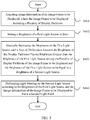
- FIG. 1 is a flowchart of an image display method provided by a first embodiment of the present disclosure.
- the image display method can be used in an image display apparatus and a projection device including the image display apparatus, such as a cinema machines, laser televisions, engineering machines, business and education machines, wall splicing device, and micro-projection devices.
- the image display method of the present embodiment can be applied in the image display apparatus.
- the image display apparatus includes a first light source and a second light source, and is configured to provide a specific brightness by means of the cooperation of the first light source and the second light source.
- the image display method of the present embodiment can include the following steps.
- step S101 image information of an image frame to be displayed is acquired, wherein the image frame to be displayed includes a plurality of display partitions.
- the display partitions are obtained by performing partition dividing in a preset dividing manner on the image frame to be displayed.
- the preset dividing manner can be a way with which the image frame to be displayed is divided, according to division setting data, into a preset number of rectangle regions having a same size.
- the preset dividing manner can be a way with which the image frame to be displayed is divided, in a default manner, into a default number of rectangle regions having a same size.
- the shape of the divided region can also be other shapes such as a circle and a regular hexagon.
- the division setting data can be default setting data, or manual setting data used for obtaining a preset number of display partitions.
- the image frame to be displayed is an image that the image display apparatus currently needs to display or a projection device needs to project.
- the image information is data that can represent the color and/or brightness of pixels in the image.
- step S102 Based on the image information of the image frame to be displayed, brightness of a first light source having a first light field is adjusted, and a light steering is performed on a second light source to form a second light field, such that the first light field provided by the first light source and the second light field provided by the second light source to cooperate to satisfy a displaying of each display partition of the image frame to be displayed.
- the adjustment based on the image information of the image frame to be displayed has the following implementable manners:
- the cooperation of satisfying the display of each of the plurality of display partitions of the image frame to be displayed is that the brightness of the first light field provided by the first light source satisfies the set brightness condition, that is the display of each display partition of the image frame to be displayed is satisfied, thus there is no need to adjust the second light source or even to turn on the second light source.
- the cooperation of satisfying the displaying of each display partition of the image frame to be displayed is that the light distribution of the second light field formed by modulating the light provided by the second light source satisfies the brightness distribution of each display partition, thus there is no need to adjust the first light source or even to turn on the first light source.
- the cooperation of satisfying the displaying of each display partition of the image frame to be displayed is that the brightness of the first light source and the brightness of the second light source are dynamically adjusted respectively such that the cooperation the first light field of the first light source and the second light field of the second light source properly satisfies the display of each display partition of the image frame to be displayed.
- the brightness of the first light source is adjusted to obtain the first light field
- the light steering is performed on the second light source to obtain the second light field
- the adjusted first light source and the second light source cooperate to satisfy the display of each display partition of the image frame to be displayed.
- the display to be satisfied of each display partition of the image frame to be displayed can be capable of satisfying the display brightness of each display partition of the image frame to be displayed, or can be capable of satisfying the display brightness of each display partition of the image frame to be displayed in a specific brightness.
- the brightness provided by the first light source and/or the brightness provided by the second light source can be selectively adjusted according to the image information of the image frame to be displayed, which can reasonably save energy , provide image display light of the specific brightness, relatively increase the provided brightness range, realize the display of high dynamic range images, and also improve the detail expression of dark field of the image to be displayed.
- the brightness provided by the first light source and/or the brightness of the second light source may cooperate to restore the brightness of each display partition of the image frame to be displayed.
- the first light source can be used for providing the background brightness of each display partition of the image frame to be displayed, and the second light source can be used for providing the brightness of the high-brightness display partition among the display partitions, thereby realizing the brightness cooperation of the first light source and the second light source.
- the first light source can be an adjustable light source, so the brightness provided by the first light source can be high or low; the second light source can be a light source with constant brightness, and a light steering is performed, by a light steering device, on the illumination light provided by the second light source to form the second light field corresponding to the position and brightness of each high-brightness display partition.
- the brightness provided by the first light source can be lower, it is beneficial to obtain the global dimming effect, and the light field formed by light steering of the light steering device can increase the peak brightness of the display image, thereby increasing the intra-frame contrast and achieving better image display effect in the high dynamic range.
- the power of the first light source can be relatively reduced, which saves energy.
- the brightness of the second light source can has a maximum brightness value that the second light source can provide or a preset brightness value.
- the preset brightness value can be a brightness value obtained by data statistics and/or experience, which can prolong the working life of the second light source.
- FIG. 2 is a flowchart of an image display method provided by a second embodiment of the present disclosure.
- the present embodiment includes steps, such as a step of determining whether the brightness of the second light source satisfies the display of the image frame to be displayed.
- steps such as a step of determining whether the brightness of the second light source satisfies the display of the image frame to be displayed.
- the image display method shown in FIG. 2 can be applied to a projection apparatus and a projection device including the projection apparatus. As shown in FIG. 2 , the image display method can include the following steps.
- step S201 image information of an image frame to be displayed is acquired, where the image frame to be displayed includes a plurality of display partitions.
- step S202 it is determined whether brightness of the second light source satisfies displaying of the image frame to be displayed.
- step S203 if the brightness of the second light source can satisfy the displaying of the image frame to be displayed, step S203 is executed, otherwise, step S204 is executed.
- the brightness provided by the second light source can meet a set brightness or restore the brightness of the image frame to be displayed, it can be regarded that the brightness of the second light source can satisfy the displaying of the image frame to be displayed.
- the brightness of the second light source is a constant value
- the first light source is not turned on and light steering is performed in a preset manner so as to distribute a remaining brightness value of the second light source after satisfying the displaying of the image frame to be displayed to the plurality of display partitions of the image frame to be displayed.
- the power of the second light source is not adjustable, so the brightness provided by the second light source is a constant value.
- the brightness range of each display partition after the light steering is relatively fixed, and the maximum brightness value is also a relatively constant value.
- the preset manner can be an equal distribution of brightness, or other distribution manners.
- the brightness of the second light source is a constant value
- the first light source is turned on, and according to the image information of the image frame to be displayed, the brightness of the first light source having the first light field is adjusted and light steering is performed on the second light source to form the second light field.
- the power of the first light source can be adjusted, such that the brightness provided by the first light source can be adjusted to cooperate the brightness of the second light source to satisfy the display brightness of each display partition of the image frame to be displayed.
- the brightness of the second light source can also be a variable value, so the first light source and the second light source can be adjusted to an assigned brightness at the same time, or any one of the light sources can be adjusted to the assigned brightness first, and then the other one of the light sources can be adjusted to the assigned brightness.
- the first light source after acquiring the image information of the image frame to be displayed, it is determined whether the brightness of the second light source can satisfy the display brightness of the image frame to be displayed. If the brightness of the second light source can satisfy the display brightness of the image frame to be displayed, the first light source is not turned on; if not, the first light source is turned on to provide the corresponding brightness, such that the first light source can be turned on purposefully according to the image information of the image frame to be displayed to satisfy the display brightness of the image frame to be displayed, and at the same time it reduces energy consumption.
- FIG. 3 is a flowchart of an image display method provided by a third embodiment of the present disclosure.
- the present embodiment includes steps, such as a step of determining whether the brightness of the first light source is equal to the brightness of the display partition having a maximum brightness in the image frame to be displayed.
- steps such as a step of determining whether the brightness of the first light source is equal to the brightness of the display partition having a maximum brightness in the image frame to be displayed.
- the image display method shown in FIG. 3 can be applied to a projection apparatus and a projection device including the projection apparatus. As shown in FIG. 3 , the image display method can include the following steps.
- step S301 image information of an image frame to be displayed is acquired, where the image frame to be displayed includes a plurality of display partitions.
- the image information of the image frame to be displayed can include the brightness information of each display partition.
- the display partitions are partitions obtained by performing partition dividing in a preset dividing manner on the image frame to be displayed.
- the preset dividing manner can be a way with which the image frame to be displayed is divided, according to division setting data, into a preset number of rectangle regions having a same size.
- the preset dividing manner can be a way with which the image frame to be displayed is divided, in a default manner, into a default number of rectangle regions having a same size.
- the shape of the divided region can also be other shapes such as a circle and a regular hexagon.
- the division setting data can be default setting data, or manual setting data used for obtaining a preset number of display partitions.
- the brightness of the first light source is set to be the same as brightness of the display partition with a maximum brightness among the plurality of display partitions of the image frame to be displayed.
- setting of the brightness can be achieved by assigning a value to the brightness of the display partition with the maximum brightness in the image frame to be displayed, or setting of the brightness can be achieved by adjusting in a preset adjustment manner to the brightness of the display partition with the maximum brightness in the image frame to be displayed.
- the brightness of the light field formed by the cooperation of the current first light source and second light source can be obtained.
- the brightness of the first light source is gradually decreased until a sum of at least one difference is equal to brightness of the second light source, where each of the at least one difference is a difference between brightness of one display partition having brightness greater than the brightness of the first light source among the plurality of display partitions of the image frame to be displayed and the brightness of the first light source.
- the brightness provided by the first light source properly meets the set conditions: the sum of the differences between the brightness of display partitions greater than the brightness of the first light source and the brightness of the first light source is equal to the brightness of the second light source.
- step S304 according to the brightness of the first light source and the image information of the image frame to be displayed, light steering is performed on the second light source to from the second light field.
- the modulation data used for performing light steering on the second light source can be determined based on the brightness of the first light source, and then the light steering and modulation are performed on the light provided by the second light source using the modulation data to obtain the desired second light field.
- the desired second light filed can be the superposition of the brightness of the first light field of the first light source and the second light field of the second light source, and the superposition can exactly restore the brightness of the image frame to be displayed; or the desired second light filed can be the superposition of the brightness of the first light field of the first light source and the second light field of the second light source, and the superposition is within the brightness restoration requirement range for restoring the image frame to be displayed.
- the brightness of the first light source is set to the maximum brightness corresponding to the maximum brightness partition of the image frame to be displayed, and then the brightness is adjusted in a gradually-decreasing manner, and the brightness provided by the first light source satisfies that the sum of the differences between the brightness of the display partitions with brightness greater than the brightness of the first light source among the plurality of display partitions of the image frame to be displayed and the brightness of the first light source is equal to the brightness of the second light source.
- the obtained brightness of the first light source and the brightness provided by the second light source cooperate to satisfy the displaying of each display partition of the image frame to be displayed, thereby realizing the brightness cooperation of the first light source and the second light source.
- FIG. 4 is a schematic diagram showing brightness adjusting corresponding to the third embodiment.
- the brightness S2 of the second light source is a constant value of 85 nits
- the acquired image information of the image frame to be displayed indicates that the display partitions include eight display partitions
- the brightness of the first display partition to the eighth display are respectively 10 nits, 0 nit, 20 nits, 35 nits, 40 nits, 15 nits, 25 nits, and 5 nits.
- the display partition with the maximum brightness is the fifth display partition having brightness of 40 nits. Therefore, the brightness S1 of the first light source is set to 40 nits correspondingly. Then, the brightness of the first light source is gradually decreased to satisfy that the sum of the differences between the brightness of the display partitions with brightness greater than the brightness of the first light source among the plurality of display partitions of the image frame to be displayed and the brightness of the first light source is equal to the brightness of the second light source.
- FIG. 5 is a flowchart of an image display method provided by a fourth embodiment of the present disclosure.
- the present embodiment includes steps, such as a step of setting the brightness of the second light source to zero.
- steps such as a step of setting the brightness of the second light source to zero.
- the image display method shown in FIG. 5 can be applied to a projection apparatus and a projection device including the projection apparatus. As shown in FIG. 5 , the image display method can include the following steps.
- step S401 image information of an image frame to be displayed is acquired, where the image frame to be displayed includes a plurality of display partitions.
- step S402 brightness of a first light source is set to zero.
- the state of the first light source can be the turned-off state.
- the brightness of the first light source is gradually increased until a sum of differences between the brightness of the display partitions with brightness greater than the brightness of the first light source among the plurality of display partitions of the image frame to be displayed and the brightness of the first light source is equal to brightness of the second light source.
- the brightness provided by the first light source exactly meets the set conditions: the sum of the differences between the brightness of display partitions greater than the brightness of the first light source and the brightness of the first light source is equal to the brightness of the second light source.
- step S404 according to the brightness of the first light source and the image information of the image frame to be displayed, light steering is performed on the second light source to from the second light field.
- the modulation data for performing the light steering on the second light source can be determined based on the brightness of the first light source similarly, and then light steering and modulation are performed on the light provided by the second light source using the modulation data to obtain the desired second light field.
- the desired second light filed can be the superposition of the brightness of the first light field of the first light source and the second light field of the second light source, and the superposition can exactly restore the brightness of the image frame to be displayed; or the desired second light filed can be the superposition of the brightness of the first light field of the first light source and the second light field of the second light source, and the superposition is within the brightness restoration requirement range for restoring the image frame to be displayed.
- the brightness of the first light source is set to zero, and then the brightness is adjusted in a gradually-increasing manner, and the brightness provided by the first light source satisfies that the sum of the differences between the brightness of the display partitions with brightness greater than the brightness of the first light source among the plurality of display partitions of the image frame to be displayed and the brightness of the first light source is equal to the brightness of the second light source.
- the obtained brightness of the first light source and the brightness provided by the second light source cooperate to satisfy the displaying of each display partition of the image frame to be displayed, thereby realizing the brightness cooperation of the first light source and the second light source.
- FIG. 6 is a schematic diagram showing brightness adjusting corresponding to the fourth embodiment.
- the brightness S2 of the second light source is a constant value of 85 nits
- the acquired image information of the image frame to be displayed indicates that the display partitions include eight display partitions
- the brightness of the first display partition to the eighth display are respectively 10 nits, 0 nit, 20 nits, 35 nits, 40 nits, 15 nits, 25 nits, and 5 nits.
- FIG. 7 is a schematic block diagram of an image display apparatus provided by an embodiment of the present disclosure.
- an image display apparatus 100 shown in FIG. 7 can include a first light source 11 and a second light source 12.
- the brightness of the first light source 11 is adjusted according to image information of an image frame to be displayed and the brightness of the second light source 12, to provide a first light field.
- the second light source 12 includes a light steering module 121 configured to perform light steering on the second light source according to the image information of the image frame to be displayed to form a second light field, such that a first light field provided by the first light source and the second light field provided by the second light source cooperate to satisfy displaying of each display partition of the image frame to be displayed.
- a light steering module 121 configured to perform light steering on the second light source according to the image information of the image frame to be displayed to form a second light field, such that a first light field provided by the first light source and the second light field provided by the second light source cooperate to satisfy displaying of each display partition of the image frame to be displayed.
- the division of the display partition of the image frame to be displayed corresponds to the distribution position of the light field generated after the modulation of the light guide module 121.
- it can also make it corresponding to the modulated brightness.
- the image display apparatus of the present embodiment can further include a control module electrically connected to the first light source.
- the control module turns off the first light source to reduce the power consumption.
- the light steering module can be a phase modulation liquid crystal device or a deformable mirror.
- the present disclosure further provides a projection device, and the projection device includes the image display apparatus of the present embodiment. Further, the projection device can further include a light combiner, and the light combiner is configured to guide the first light field of the first light source and the second light field of the second light source that are obtained according to the embodiment of the image displaying method, to propagate a same light path to obtain composite illumination light.
- the projection device can further include a spatial light modulator, and the spatial light modulator is configured to modulate the composite illumination light according to the image information of the image frame to be displayed to output image light to be projected.
- the outputted projection image light can be emitted through a projection lens to achieve a certain degree of reproduction of the image frame to be displayed
- FIG. 8 is a schematic diagram of a projection device provided by a first embodiment of the present disclosure.
- the projection device 100 includes a light source system, a spatial light modulator 106, and a projection lens 107.
- the light source system can include a first light source 101a and a second light source 101b.
- the brightness of the first light source 101a can be adjusted according to the image information of the image frame to be displayed and the brightness of the second light source, and specifically, it can be a laser light source, a laser fluorescent light source, or a light emitting diode light source.
- first illumination light emitted by the first light source 101a can be subjected to light homogenization processing by a light homogenization device 102, so as to achieve uniform light distribution of the first illumination light.
- the homogenized first illumination light has a first light field.
- the second light source 101b emits second illumination light at a preset light source power, and the brightness of the second illumination light is a constant value.
- the second illumination light is modulated by a light steering device 104 to obtain modulated illumination light having a second light field, such that the first light field provided by the first light source 101a and the second light field provided by the second light source cooperate to satisfy displaying of each display partition of the image frame to be displayed.
- the second illumination light is a constant value, and after the light steering and modulation that are performed by the light steering device, the total light brightness of each brightness distribution is still a constant value and not changed.
- the image frame to be displayed can be divided into 30 ⁇ 40 display partitions, and brightness statistics of each display partition can be performed.
- the second light field modulated by the light steering device 104 also has a brightness distribution corresponding to 30 ⁇ 40 display partitions.
- the first illumination light that has been homogenized by the light homogenization device 102 is reflected to a light combiner 105 by a mirror 103, and the modulated illumination light generated by the light steering device 104 also propagates to the light combiner 105.
- the light combiner 105 guides the received first illumination light and the modulated illumination light to the same light path to propagate to obtain composite illumination light.
- the light combiner 105 is a polarization combiner
- the first illumination light emitted by the first light source 101a is S-polarized light
- the modulated illumination light obtained by modulating the second illumination light emitted by the second light source 101b is P-polarized light.
- both a wavelength difference between the first illumination light and the second illumination light and a wavelength difference between the first illumination light and the modulated illumination light obtained by modulation are 10 nanometers.
- the wavelength of the first illumination light is 455 nanometers
- the wavelength of the second illumination light and the wavelength of the modulated illumination light are 465 nanometers.
- the composite illumination light obtained by the light combiner 105 is transmitted to the spatial light modulator 106, and the spatial light modulator 106 modulates the composite illumination light according to the image information of the image frame to be displayed, so as to obtain the to-be-projected image light that will be projected by the projection lens 107.
- the spatial light modulator 106 is a digital micromirror.
- the first light source 101a and the second light source 101b are adjusted according to the acquired image information of the image frame to be displayed, so that the first light field provided by the first light source 101a and the second light field provided by the second light source 101b can satisfy the displaying of each display partition of the image frame to be displayed.
- the composite illumination light can include background illumination light which is provided by the first light source 101a and used for the basic brightness of the image frame to be displayed, and can also include the compensation illumination light which is provided by the second light source 101b and is used for the high-brightness area of the image frame to be displayed, which is beneficial to realize the global dimming effect of the projection image and beneficial to the detail expression of the dark field of the projection image, and at the same time, it can also achieve image effects of high-brightness and high dynamic range to enhance the visual effect.
- FIG. 9 is a schematic diagram of a projection device provided by a second embodiment of the present disclosure.
- a projection device 200 includes a light source system, a phosphor color wheel 206, a spatial light modulator 207, and a projection lens 208.
- a first light source 201a and a second light source 201b are both blue laser light sources
- the light source power of the first light source 201a is greater than the light source power of the second light source 201b
- the brightness provided by the first light source 201a and the brightness provided by the second light source 201b are determined according to image information of an image frame to be displayed.
- First illumination light emitted by the first light source 201a is used for providing background illumination light of the image frame to be displayed
- second illumination light emitted by the second light source 201b is used for providing compensation illumination light for the high-brightness area in the image frame to be displayed.
- the first illumination light emitted by the first light source 201a is homogenized by a light homogenization device 202
- the first illumination light is reflected by a mirror 203 to a light combiner 205
- the second illumination light emitted by the second light source 201b is guided and modulated by a light steering device 204 to obtain modulated illumination light
- the modulated illumination light is transmitted to a light combiner 205.
- the light combiner 205 guides the received first illumination light and the modulated illumination light to the same light path to obtain composite illumination light. It can be understood that since the first light source 201a and the second light source 201b are both blue laser light sources, the illumination light processed by the light homogenization device 202 and the light steering device 204 is still blue laser illumination light.
- a phosphor color wheel 206 is provided on the light path of the composite illumination light, and the phosphor color wheel 206 is configured to convert the composite illumination light to obtain the three primary colors composite illumination light, and is specifically configured to convert the blue laser illumination light into red illumination light, green illumination light, and blue illumination light.
- the red illumination light and the green illumination light are both fluorescence illumination light
- the blue illumination light is fluorescence illumination light or laser illumination light. If the blue illumination light is fluorescence illumination light, the phosphor color wheel is provided with a corresponding blue light conversion area; if the blue illumination light is laser illumination light, the phosphor color wheel can be provided with a corresponding blue light-transmissive area or blue light reflection area.
- the red illumination light, the green illumination light, and the blue illumination light that are obtained by the phosphor color wheel 206 are transmitted to the spatial light modulator 207, and the spatial light modulator 207 modulates the received illumination light according to the image information of the image frame to be displayed so as to obtain the to-be-projected image light that will be projected by the projection lens 208.
- the spatial light modulator 207 can be a single-sheet digital micromirror or a three-sheet digital micromirror.
- the phosphor color wheel 206 is an RGB segmented color wheel, so for each image frame to be displayed, it needs to project the red light of the image frame to be displayed, the green light of the image frame to be displayed, and the blue light of the image frame to be displayed in three periods of red, green, and blue, respectively.
- a color image is formed on the human senses, and in the light source system, for each image frame to be displayed, it only needs to adjust the power once, which saves computing resources.
- the spatial light modulator 207 is a three-sheet digital micromirror
- the red light of the image to be projected, the green light of the image to be projected, and the blue light of the image to be projected can be projected in the same period, and they are directly combined into a color image that can be directly observed by the naked eye.
- FIG. 10 is a schematic diagram of a projection device provided by a third embodiment of the present disclosure.
- a projection device 300 includes a light source system, a spatial light modulator 309, and a projection lens 310.
- the light source system further includes a first light source 301a and a light homogenization device 302 for homogenizing first illumination light emitted by the first light source 301a.
- the homogenized first illumination light is irradiated on a phosphor color wheel 303, and the phosphor color wheel 303 converts the received illumination light into fluorescence illumination light of the corresponding color (such as three primary colors fluorescence illumination light in time division).
- a polarization conversion system 304 performs polarization conversion processing on the fluorescence illumination light to obtain fluorescence illumination light with linear polarization.
- a light combiner 308 is a polarization combiner, so the fluorescence illumination light generated by the conversion of the phosphor color wheel 303 is converted, by the polarization conversion system 304, into illumination light with linear polarization.
- the second light source includes a red laser 306a, a green laser 306b, and a blue laser 306c that are turned on in a time division manner to generate color light synchronizing with the three primary colors fluorescence illumination light (the aforementioned first illumination light) generated by the phosphor color wheel 303.
- a light steering device 307 performs light steering and modulation on each of the three primary colors illumination light (the aforementioned second illumination light) to obtain the three primary colors modulated illumination light.
- the light combiner 308 guides the three primary colors fluorescence illumination light and the three primary colors modulated illumination light to the same light path to propagate, to the spatial light modulator 309.
- the first light source 301a is adjusted to obtain the first illumination light having a first light field.
- the light steering device 307 performs light steering and modulation on the illumination light emitted by lasers to form various colors of modulated illumination light that each has a second light field.
- the modulated illumination light and the first illumination light can cooperate to still satisfy the displaying of each display partition of the image frame to be displayed.
- the phosphor color wheel 303 is a wavelength conversion device that can convert the first illumination light emitted by the first light source 301a into red fluorescence illumination light and green fluorescence illumination light that provide the DCI P3 color gamut.
- the laser emitted by the red laser 306a, the green laser 306b, and the blue laser 306c of the second light source is the illumination light for providing the REC2020 color gamut, thereby enhancing the color gamut of the projection image and improving the color expression of the projection image.
- the spatial light modulator 309 After receiving the corresponding-color fluorescence and the modulated illumination light, the spatial light modulator 309 modulates the corresponding-color fluorescence and the modulated illumination light according to the image information of the image frame to be displayed, to obtain the to-be-projected image light to be projected by the projection lens 310. It can be understood that the spatial light modulator 309 here is a digital micromirror.
- FIG. 11 is a schematic diagram of a projection device provided by a fourth embodiment of the present disclosure.
- a projection device 400 includes three light source systems, a spatial light modulator 402, and a projection lens 403.
- the light source systems are configured to generate composite illumination light having various colors.
- a red-light light source system 401a is configured to generate red composite illumination light
- a green-light light source system 401b is configured to generate green composite illumination light
- a blue-light light source system 401c is configured to generate blue composite illumination light.
- the generated red composite illumination light, green composite illumination light, and blue composite illumination light are emitted to the spatial light modulator 402 in a timing sequence.
- the spatial light modulator 402 modulates the corresponding illumination light according to the image information of the image frame to be displayed so as to obtain the to-be-projected image light that will be projected by the projection lens 403.
- the first light source of each light source system can be a laser light source of the same specification, and the first illumination light generated by the first light source is homogenized by a light homogenization device, and a mirror is provided to reflect the homogenized first illumination light to a light combiner in the light source system.
- the second light source of each light source system can be a laser light source with the same power, and only the color of the emitted laser light is different.
- the second illumination light emitted by the laser light source of each color can be modulated by the light steering devices of the same specification to generate the modulated illumination light of the corresponding color. Then, with the light combiner, the corresponding red composite illumination light, green composite illumination light and blue composite illumination light are generated.
- the first light field provided by the first light source and the second light field provided by the second light source of the corresponding color cooperate to satisfy the displaying of each display partition of the image frame to be displayed.
- each digital micromirror can modulate the composite illumination light of one color, such that the to-be-projected image light of various colors are generated and are projected by the projection lens 403 simultaneously. In this way, the color image that can be viewed by the naked eye is directly generated.
- the projection system provided by the present disclosure applies the image display method provided by the present disclosure, by using the acquired image information of the image frame to be displayed, the brightness of the first light source is adjusted to obtain the first light field, and at the same time, the light steering is performed on the second light source to obtain the second light field.
- the adjusted first light field and the second light field cooperate to satisfy the displaying of each display partition of the image frame to be displayed.
- the satisfying the displaying of each display partition of the image frame to be displayed can indicate satisfying the display brightness of each display partition of the image frame to be displayed, or can indicates satisfying the display brightness of each display partition of the image frame to be displayed in a specific brightness.
- the brightness provided by the first light source and/or the brightness provided by the second light source can be selectively adjusted according to the image information of the image frame to be displayed, which can reasonably save energy, provide image display light of the specific brightness, relatively increase the provided brightness range, realize the display of high dynamic range images, and improve the detail expression of dark field of the image to be displayed.
Landscapes
- Engineering & Computer Science (AREA)
- Multimedia (AREA)
- Signal Processing (AREA)
- Physics & Mathematics (AREA)
- General Physics & Mathematics (AREA)
- Computer Hardware Design (AREA)
- Theoretical Computer Science (AREA)
- Optics & Photonics (AREA)
- Transforming Electric Information Into Light Information (AREA)
- Projection Apparatus (AREA)
- Liquid Crystal Display Device Control (AREA)
- Control Of Indicators Other Than Cathode Ray Tubes (AREA)
- Controls And Circuits For Display Device (AREA)
Applications Claiming Priority (2)
| Application Number | Priority Date | Filing Date | Title |
|---|---|---|---|
| CN201811109860.3A CN110941133B (zh) | 2018-09-21 | 2018-09-21 | 图像显示方法、装置及投影设备 |
| PCT/CN2019/086926 WO2020057151A1 (zh) | 2018-09-21 | 2019-05-15 | 图像显示方法、装置及投影设备 |
Publications (2)
| Publication Number | Publication Date |
|---|---|
| EP3855422A1 true EP3855422A1 (de) | 2021-07-28 |
| EP3855422A4 EP3855422A4 (de) | 2022-07-27 |
Family
ID=69888273
Family Applications (1)
| Application Number | Title | Priority Date | Filing Date |
|---|---|---|---|
| EP19861832.4A Pending EP3855422A4 (de) | 2018-09-21 | 2019-05-15 | Bildanzeigeverfahren und -vorrichtung und projektionsvorrichtung |
Country Status (4)
| Country | Link |
|---|---|
| US (1) | US11336874B2 (de) |
| EP (1) | EP3855422A4 (de) |
| CN (1) | CN110941133B (de) |
| WO (1) | WO2020057151A1 (de) |
Families Citing this family (2)
| Publication number | Priority date | Publication date | Assignee | Title |
|---|---|---|---|---|
| CN116193089B (zh) * | 2023-02-23 | 2025-07-25 | 宜宾市极米光电有限公司 | 投影图像显示方法、装置、设备及存储介质 |
| WO2026015397A1 (en) * | 2024-07-12 | 2026-01-15 | Dolby Laboratories Licensing Corporation | High contrast imaging using multi-path projection systems |
Family Cites Families (11)
| Publication number | Priority date | Publication date | Assignee | Title |
|---|---|---|---|---|
| US7438423B2 (en) * | 2005-08-29 | 2008-10-21 | 3M Innovative Properties Company | Illumination system and projection system incorporating same |
| JP5140869B2 (ja) * | 2007-08-06 | 2013-02-13 | 株式会社リコー | 画像投影方法および画像投影装置 |
| US7551341B1 (en) | 2008-01-28 | 2009-06-23 | Dolby Laboratories Licensing Corporation | Serial modulation display having binary light modulation stage |
| CN101887692B (zh) | 2009-05-13 | 2012-08-22 | 胜华科技股份有限公司 | 影像显示方法 |
| EP3241073B1 (de) | 2014-12-31 | 2020-09-09 | Dolby Laboratories Licensing Corporation | Verfahren und systeme für bildprojektoren mit hohem dynamischem bereich |
| CN104882097B (zh) | 2015-06-08 | 2017-11-21 | 西安电子科技大学 | 基于环境光的图像显示方法及系统 |
| JP2018169413A (ja) | 2015-08-28 | 2018-11-01 | パナソニックIpマネジメント株式会社 | 照明装置および照明システム |
| JP7053103B2 (ja) * | 2015-10-06 | 2022-04-12 | エムティティ イノベーション インコーポレイテッド | 投影システムおよび方法 |
| CN105573032B (zh) * | 2015-12-18 | 2017-08-01 | 深圳市帅映科技股份有限公司 | 一种高亮度、色度均匀的投影系统 |
| CN107621746B (zh) * | 2016-07-15 | 2019-07-02 | 深圳光峰科技股份有限公司 | 发光装置及相关投影系统 |
| CN110874002B (zh) * | 2018-08-31 | 2021-12-21 | 深圳光峰科技股份有限公司 | 动态调节显示系统色域的系统、方法及显示系统 |
-
2018
- 2018-09-21 CN CN201811109860.3A patent/CN110941133B/zh active Active
-
2019
- 2019-05-15 US US17/278,517 patent/US11336874B2/en active Active
- 2019-05-15 EP EP19861832.4A patent/EP3855422A4/de active Pending
- 2019-05-15 WO PCT/CN2019/086926 patent/WO2020057151A1/zh not_active Ceased
Also Published As
| Publication number | Publication date |
|---|---|
| US11336874B2 (en) | 2022-05-17 |
| CN110941133A (zh) | 2020-03-31 |
| US20220038666A1 (en) | 2022-02-03 |
| EP3855422A4 (de) | 2022-07-27 |
| WO2020057151A1 (zh) | 2020-03-26 |
| CN110941133B (zh) | 2022-04-22 |
Similar Documents
| Publication | Publication Date | Title |
|---|---|---|
| US9667929B2 (en) | Display uniformity compensation method, optical modulation apparatus, signal processor, and projection system | |
| EP3066829B1 (de) | Einzel- und multi-modulator-projektorsysteme mit globaler verdunkelung | |
| JP4552986B2 (ja) | 画像表示装置 | |
| US20050195223A1 (en) | Light modulating apparatus, optical display apparatus, light modulation control program, optical display apparatus control program, light modulation control method, and optical display apparatus control method | |
| CN110944161B (zh) | 投影系统及投影显示方法 | |
| US9462215B2 (en) | Enhanced global dimming for projector display systems | |
| US11380237B2 (en) | Display device and display method | |
| WO2020177588A1 (zh) | 一种显示系统 | |
| EP3855422A1 (de) | Bildanzeigeverfahren und -vorrichtung und projektionsvorrichtung | |
| CN111487840B (zh) | 显示设备的光源控制方法及显示设备 | |
| KR20170125120A (ko) | 멀티-하프-톤 이미징 및 이중 변조 투사/이중 변조 레이저 투사 | |
| CN113900323A (zh) | 一种单板式液晶投影装置 | |
| US10965918B2 (en) | Projection system and image modulation method | |
| US11630381B2 (en) | Excitation light intensity control system and method, and projection system | |
| US20170061851A1 (en) | Large gamut pixel and subtractive mask for a visual presentation | |
| JP2012194450A (ja) | 光源制御装置及び方法並びにプロジェクター | |
| WO2019024361A1 (zh) | 显示设备及显示方法 | |
| CN110278420A (zh) | 图像处理装置、显示设备、图像处理与显示装置及方法 | |
| EP3988999A1 (de) | Farbkorrekturverfahren für beleuchtungssystem und beleuchtungssystem | |
| JP2009098627A (ja) | 投写型映像表示装置 | |
| US20240146886A1 (en) | Projector apparatus, light source device, and light source drive method | |
| JP2004138733A (ja) | 映像表示装置 | |
| HK1226227A1 (en) | Single and multi-modulator projector systems with global dimming |
Legal Events
| Date | Code | Title | Description |
|---|---|---|---|
| STAA | Information on the status of an ep patent application or granted ep patent |
Free format text: STATUS: THE INTERNATIONAL PUBLICATION HAS BEEN MADE |
|
| PUAI | Public reference made under article 153(3) epc to a published international application that has entered the european phase |
Free format text: ORIGINAL CODE: 0009012 |
|
| STAA | Information on the status of an ep patent application or granted ep patent |
Free format text: STATUS: REQUEST FOR EXAMINATION WAS MADE |
|
| 17P | Request for examination filed |
Effective date: 20210421 |
|
| AK | Designated contracting states |
Kind code of ref document: A1 Designated state(s): AL AT BE BG CH CY CZ DE DK EE ES FI FR GB GR HR HU IE IS IT LI LT LU LV MC MK MT NL NO PL PT RO RS SE SI SK SM TR |
|
| DAV | Request for validation of the european patent (deleted) | ||
| DAX | Request for extension of the european patent (deleted) | ||
| RIC1 | Information provided on ipc code assigned before grant |
Ipc: G03B 21/00 20060101ALI20220318BHEP Ipc: G09G 3/34 20060101ALI20220318BHEP Ipc: H04N 9/31 20060101AFI20220318BHEP |
|
| REG | Reference to a national code |
Ref country code: DE Ref legal event code: R079 Free format text: PREVIOUS MAIN CLASS: G09G0003340000 Ipc: H04N0009310000 |
|
| A4 | Supplementary search report drawn up and despatched |
Effective date: 20220624 |
|
| RIC1 | Information provided on ipc code assigned before grant |
Ipc: G03B 21/00 20060101ALI20220620BHEP Ipc: G09G 3/34 20060101ALI20220620BHEP Ipc: H04N 9/31 20060101AFI20220620BHEP |
|
| STAA | Information on the status of an ep patent application or granted ep patent |
Free format text: STATUS: EXAMINATION IS IN PROGRESS |
|
| 17Q | First examination report despatched |
Effective date: 20240702 |