EP3854664A1 - Motor vehicle comprising an aerodynamic device - Google Patents
Motor vehicle comprising an aerodynamic device Download PDFInfo
- Publication number
- EP3854664A1 EP3854664A1 EP21152829.4A EP21152829A EP3854664A1 EP 3854664 A1 EP3854664 A1 EP 3854664A1 EP 21152829 A EP21152829 A EP 21152829A EP 3854664 A1 EP3854664 A1 EP 3854664A1
- Authority
- EP
- European Patent Office
- Prior art keywords
- vehicle
- deflector
- lateral
- motor vehicle
- actuator
- Prior art date
- Legal status (The legal status is an assumption and is not a legal conclusion. Google has not performed a legal analysis and makes no representation as to the accuracy of the status listed.)
- Granted
Links
- 230000011664 signaling Effects 0.000 claims description 9
- 238000000034 method Methods 0.000 claims description 3
- 238000012423 maintenance Methods 0.000 description 1
Images


Classifications
-
- B—PERFORMING OPERATIONS; TRANSPORTING
- B62—LAND VEHICLES FOR TRAVELLING OTHERWISE THAN ON RAILS
- B62D—MOTOR VEHICLES; TRAILERS
- B62D35/00—Vehicle bodies characterised by streamlining
- B62D35/001—For commercial vehicles or tractor-trailer combinations, e.g. caravans
-
- B—PERFORMING OPERATIONS; TRANSPORTING
- B60—VEHICLES IN GENERAL
- B60Q—ARRANGEMENT OF SIGNALLING OR LIGHTING DEVICES, THE MOUNTING OR SUPPORTING THEREOF OR CIRCUITS THEREFOR, FOR VEHICLES IN GENERAL
- B60Q1/00—Arrangement of optical signalling or lighting devices, the mounting or supporting thereof or circuits therefor
- B60Q1/26—Arrangement of optical signalling or lighting devices, the mounting or supporting thereof or circuits therefor the devices being primarily intended to indicate the vehicle, or parts thereof, or to give signals, to other traffic
- B60Q1/2661—Arrangement of optical signalling or lighting devices, the mounting or supporting thereof or circuits therefor the devices being primarily intended to indicate the vehicle, or parts thereof, or to give signals, to other traffic mounted on parts having other functions
-
- B—PERFORMING OPERATIONS; TRANSPORTING
- B60—VEHICLES IN GENERAL
- B60Q—ARRANGEMENT OF SIGNALLING OR LIGHTING DEVICES, THE MOUNTING OR SUPPORTING THEREOF OR CIRCUITS THEREFOR, FOR VEHICLES IN GENERAL
- B60Q1/00—Arrangement of optical signalling or lighting devices, the mounting or supporting thereof or circuits therefor
- B60Q1/26—Arrangement of optical signalling or lighting devices, the mounting or supporting thereof or circuits therefor the devices being primarily intended to indicate the vehicle, or parts thereof, or to give signals, to other traffic
- B60Q1/2692—Arrangement of optical signalling or lighting devices, the mounting or supporting thereof or circuits therefor the devices being primarily intended to indicate the vehicle, or parts thereof, or to give signals, to other traffic retractable lights
-
- B—PERFORMING OPERATIONS; TRANSPORTING
- B60—VEHICLES IN GENERAL
- B60Q—ARRANGEMENT OF SIGNALLING OR LIGHTING DEVICES, THE MOUNTING OR SUPPORTING THEREOF OR CIRCUITS THEREFOR, FOR VEHICLES IN GENERAL
- B60Q1/00—Arrangement of optical signalling or lighting devices, the mounting or supporting thereof or circuits therefor
- B60Q1/26—Arrangement of optical signalling or lighting devices, the mounting or supporting thereof or circuits therefor the devices being primarily intended to indicate the vehicle, or parts thereof, or to give signals, to other traffic
- B60Q1/30—Arrangement of optical signalling or lighting devices, the mounting or supporting thereof or circuits therefor the devices being primarily intended to indicate the vehicle, or parts thereof, or to give signals, to other traffic for indicating rear of vehicle, e.g. by means of reflecting surfaces
- B60Q1/304—Adaptations of signalling devices having a part on the vehicle body and another on the boot door
-
- Y—GENERAL TAGGING OF NEW TECHNOLOGICAL DEVELOPMENTS; GENERAL TAGGING OF CROSS-SECTIONAL TECHNOLOGIES SPANNING OVER SEVERAL SECTIONS OF THE IPC; TECHNICAL SUBJECTS COVERED BY FORMER USPC CROSS-REFERENCE ART COLLECTIONS [XRACs] AND DIGESTS
- Y02—TECHNOLOGIES OR APPLICATIONS FOR MITIGATION OR ADAPTATION AGAINST CLIMATE CHANGE
- Y02T—CLIMATE CHANGE MITIGATION TECHNOLOGIES RELATED TO TRANSPORTATION
- Y02T10/00—Road transport of goods or passengers
- Y02T10/80—Technologies aiming to reduce greenhouse gasses emissions common to all road transportation technologies
- Y02T10/82—Elements for improving aerodynamics
Landscapes
- Engineering & Computer Science (AREA)
- Mechanical Engineering (AREA)
- Chemical & Material Sciences (AREA)
- Combustion & Propulsion (AREA)
- Transportation (AREA)
- Body Structure For Vehicles (AREA)
- Power-Operated Mechanisms For Wings (AREA)
Abstract
L'invention concerne un véhicule automobile (1) comprenant sur chacun de ses côtés et dans une zone arrière du véhicule, une première surface (9) de carrosserie latérale sensiblement verticale, un déflecteur (2) arrière latéral relié à la structure (5) du véhicule par un système à biellettes (6, 7) permettant de déplacer le déflecteur (2) entre d'une part une position avant rétractée dans laquelle la surface extérieure (8) latérale du déflecteur (2) est affleurante avec la première surface (9) et d'autre part une position arrière déployée dans laquelle la surface extérieure (8) latérale du déflecteur (2) est affleurante avec une deuxième surface (10) de carrosserie latérale du véhicule, cette deuxième surface (10) de carrosserie latérale étant dissimulée par le déflecteur (2) lorsqu'il est dans la position avant rétractée.The invention relates to a motor vehicle (1) comprising on each of its sides and in a rear area of the vehicle, a first substantially vertical lateral bodywork surface (9), a lateral rear deflector (2) connected to the structure (5) of the vehicle by a linkage system (6, 7) making it possible to move the deflector (2) between on the one hand a retracted front position in which the lateral outer surface (8) of the deflector (2) is flush with the first surface ( 9) and on the other hand a deployed rear position in which the outer side surface (8) of the deflector (2) is flush with a second side body surface (10) of the vehicle, this second side body surface (10) being concealed by the deflector (2) when in the front retracted position.
Description
La présente invention concerne un déflecteur aérodynamique arrière d'un véhicule automobileThe present invention relates to a rear aerodynamic deflector of a motor vehicle
Le durcissement des normes de pollution et la réduction de la consommation poussent les constructeurs automobiles à rechercher des performances aérodynamiques optimales sur les véhicules automobiles. Dans cette optique, on cherche à améliorer la trainée aérodynamique générée à l'arrière des véhicules. Celle-ci dépend fortement de la dépression qui apparait à l'arrière du véhicule et qui est nécessairement impactée par la forme de la carrosserie. On parle de « trainée de culot » pour désigner la trainée aérodynamique soumise à cette dépression et aux turbulences à l'arrière du véhicule. Pour réduire cette dépression et améliorer la trainée aérodynamique, on connait des dispositifs consistant à réduire la surface arrière du véhicule. Le document
Le but de l'invention est donc de proposer un véhicule comprenant des déflecteurs aérodynamiques arrière s'intégrant parfaitement au véhicule tout en conservant des cotes de chargement et des dimensions d'ouvrant maximales à l'arrière du véhicule.
La présente invention a pour objet un véhicule automobile comprenant sur chacun de ses côtés et dans une zone arrière du véhicule, une première surface de carrosserie latérale sensiblement verticale, un déflecteur arrière latéral relié à la structure du véhicule par un système à biellettes permettant de déplacer le déflecteur entre d'une part une position avant rétractée dans laquelle une surface extérieure latérale du déflecteur est affleurante avec la première surface et d'autre part une position arrière déployée dans laquelle la surface extérieure latérale du déflecteur est affleurante avec une deuxième surface de carrosserie latérale du véhicule, cette deuxième surface de carrosserie latérale étant dissimulée par le déflecteur lorsqu'il est dans la position avant rétractée.The tightening of pollution standards and the reduction in consumption are pushing car manufacturers to seek optimal aerodynamic performance on motor vehicles. With this in mind, we seek to improve the aerodynamic drag generated at the rear of vehicles. This strongly depends on the depression which appears at the rear of the vehicle and which is necessarily impacted by the shape of the bodywork. The term “base drag” is used to designate the aerodynamic drag subjected to this depression and to the turbulence at the rear of the vehicle. To reduce this depression and improve the aerodynamic drag, devices are known which consist in reducing the rear surface of the vehicle. The document
The aim of the invention is therefore to provide a vehicle comprising rear aerodynamic deflectors which are perfectly integrated into the vehicle while retaining maximum loading dimensions and opening dimensions at the rear of the vehicle.
The present invention relates to a motor vehicle comprising on each of its sides and in a rear zone of the vehicle, a first substantially vertical lateral bodywork surface, a lateral rear deflector connected to the structure of the vehicle by a link system making it possible to move the deflector enters on the one hand a retracted front position in which a lateral outer surface of the deflector is flush with the first surface and on the other hand a deployed rear position in which the lateral outer surface of the deflector is flush with a second lateral bodywork surface of the vehicle, this second lateral bodywork surface being concealed by the deflector when it is in the front retracted position.
D'autres caractéristiques de l'invention sont indiquées ci-après.
Le système à biellettes comprend deux biellettes sensiblement parallèles ayant chacune une extrémité intérieure articulée sur la structure du véhicule, et une extrémité extérieure articulée sur une face intérieure du déflecteur.
La surface extérieure latérale du déflecteur dans la position arrière déployée est orientée de façon sensiblement verticale et forme un angle compris entre 10° et 20° par rapport à la direction longitudinale du véhicule, cet angle étant plus particulièrement de l'ordre de 15°.
Le déflecteur a la forme générale d'un L vue dans une section horizontale, la branche longue du L s'étendant longitudinalement sur le côté du véhicule tandis que la branche courte du L s'étend transversalement sur la face arrière du véhicule.
Le déflecteur comporte des moyens de signalisation lumineuse localisés dans la branche courte et dans une zone localisée verticalement, un faisceau électrique déployable étant prévu pour alimenter les moyens de signalisation lumineuse.
Le véhicule comprend au moins une porte battante arrière articulée par son bord latéral sur un montant vertical de structure du véhicule, entre une position fermée sensiblement parallèle à la direction transversale du véhicule et une position d'ouverture maximale formant un angle sensiblement à 180° par rapport à la position fermée, un jeu étant ménagé entre le bord latéral de la porte battante et le déflecteur en position avant rétractée quelle que soit la position angulaire de la porte entre la position fermée et la position d'ouverture maximale.
Le véhicule comprend un actionneur, notamment électrique ou pneumatique, relié à au moins l'une des biellettes pour lui imposer un pivotement par rapport à la structure, cet actionneur étant piloté par un calculateur du véhicule de façon à déployer et/ou rétracter automatiquement le déflecteur lorsque des données relatives à la vitesse du véhicule sont reçues par le calculateur.Other characteristics of the invention are indicated below.
The linkage system comprises two substantially parallel links each having an inner end articulated on the structure of the vehicle, and an outer end articulated on an inner face of the deflector.
The lateral outer surface of the deflector in the deployed rear position is oriented substantially vertical and forms an angle of between 10 ° and 20 ° with respect to the longitudinal direction of the vehicle, this angle being more particularly of the order of 15 °.
The deflector has the general shape of an L seen in a horizontal section, the long leg of the L extending longitudinally on the side of the vehicle while the short leg of the L extends transversely over the rear face of the vehicle.
The deflector comprises light signaling means located in the short branch and in a zone located vertically, a deployable electric beam being provided to supply the light signaling means.
The vehicle comprises at least one rear hinged door articulated by its lateral edge on a vertical upright of the vehicle structure, between a closed position substantially parallel to the transverse direction of the vehicle and a maximum open position forming an angle substantially at 180 ° by relative to the closed position, a clearance being provided between the lateral edge of the hinged door and the deflector in the retracted front position whatever the angular position of the door between the closed position and the maximum open position.
The vehicle comprises an actuator, in particular an electric or pneumatic actuator, connected to at least one of the connecting rods in order to force it to pivot relative to the structure, this actuator being controlled by a vehicle computer so as to automatically deploy and / or retract the deflector when data relating to the speed of the vehicle is received by the computer.
L'invention a également pour objet un procédé d'actionnement d'un déflecteur arrière latéral d'un véhicule automobile, disposé sur chacun de ses côtés et dans une zone arrière du véhicule, le déflecteur étant relié à la structure du véhicule par deux biellettes sensiblement parallèles, permettant de déplacer le déflecteur entre d'une part une position avant rétractée dans laquelle une surface extérieure latérale du déflecteur est affleurante avec une première surface de carrosserie latérale sensiblement verticale du véhicule et d'autre part une position arrière déployée dans laquelle la surface extérieure latérale du déflecteur est affleurante avec une deuxième surface de carrosserie latérale du véhicule, cette deuxième surface de carrosserie latérale étant dissimulée par le déflecteur lorsqu'il est dans la position avant rétractée, le véhicule comprenant également un actionneur, notamment électrique ou pneumatique, relié à au moins l'une des biellettes pour lui imposer un pivotement par rapport à la structure caractérisé en ce qu'il comprend les étapes suivantes :
- réception par un calculateur du véhicule de données représentatives de la vitesse du véhicule,
- comparaison entre la vitesse du véhicule et des valeurs de seuil déterminées,
- envoi d'une consigne de déploiement et de rétractation à l'actionneur commandant respectivement le déploiement et la rétractation du déflecteur lorsque la vitesse du véhicule est respectivement supérieure et inférieure à une valeur de seuil déterminée
- reception by a vehicle computer of data representative of the speed of the vehicle,
- comparison between vehicle speed and determined threshold values,
- sending of a deployment and retraction instruction to the actuator respectively controlling the deployment and retraction of the deflector when the vehicle speed is respectively above and below a determined threshold value
D'autres buts, caractéristiques et avantages de l'invention apparaîtront à la lecture de la description suivante, donnée uniquement à titre d'exemple non limitatif, et faite en référence aux dessins annexés sur lesquels :
- [
Fig 1 ] illustre schématiquement un véhicule automobile vu de côté comprenant un déflecteur arrière latéral selon l'invention ; - [
Fig 2 ] est une vue schématique du véhicule automobile de lafigure 1 , vu de l'arrière ; - [
Fig 3 ] est une vue d'une section transversale de la partie arrière latérale du véhicule automobile de lafigure 1 , suivant la ligne de coupe A-A ; - [
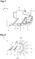
Fig 4 ] est une vue schématique analogue à lafigure 3 illustrant le débattement d'une porte arrière battante par rapport au déflecteur de l'invention en position avant rétractée ; - [
Fig. 5 ] est une vue schématique analogue à lafigure 3 illustrant le déflecteur de l'invention en position avant rétractée ; - [
Fig. 6 ] est une vue schématique analogue à lafigure 3 illustrant le déflecteur de l'invention dans une première position intermédiaire entre la position avant rétractée et la position arrière déployée ; - [
Fig. 7 ] est une vue schématique analogue à lafigure 3 illustrant le déflecteur de l'invention dans une seconde position intermédiaire entre la position avant rétractée et la position arrière déployée ; - [
Fig. 8 ] est une vue schématique analogue à lafigure 3 illustrant le déflecteur de l'invention dans la position arrière déployée ; - [
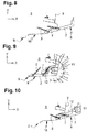
Fig. 9 ] est une vue schématique analogue à lafigure 3 suivant une autre ligne de coupe parallèle à la ligne A-A, illustrant le déflecteur de l'invention en position avant rétractée et des moyens de signalisation lumineuse ainsi que le cordon d'alimentation associé ; - [
Fig. 10 ] est une vue schématique analogue à lafigure 3 suivant une autre ligne de coupe parallèle à la ligne A-A, illustrant le déflecteur de l'invention en position arrière déployée et des moyens de signalisation lumineuse ainsi que le cordon d'alimentation associé ;
- [
Fig 1 ] schematically illustrates a motor vehicle seen from the side comprising a rear lateral deflector according to the invention; - [
Fig 2 ] is a schematic view of the motor vehicle of thefigure 1 , seen from the rear; - [
Fig 3 ] is a view of a cross section of the lateral rear part of the motor vehicle of thefigure 1 , following the cut line AA; - [
Fig 4 ] is a schematic view similar to thefigure 3 illustrating the movement of a hinged rear door relative to the deflector of the invention in the front retracted position; - [
Fig. 5 ] is a schematic view similar to thefigure 3 illustrating the deflector of the invention in the front retracted position; - [
Fig. 6 ] is a schematic view similar to thefigure 3 illustrating the deflector of the invention in a first intermediate position between the front retracted position and the rear deployed position; - [
Fig. 7 ] is a schematic view similar to thefigure 3 illustrating the deflector of the invention in a second intermediate position between the front retracted position and the rear deployed position; - [
Fig. 8 ] is a schematic view similar to thefigure 3 illustrating the deflector of the invention in the rear deployed position; - [
Fig. 9 ] is a schematic view similar to thefigure 3 along another section line parallel to line AA, illustrating the deflector of the invention in the retracted front position and light signaling means as well as the associated power cord; - [
Fig. 10 ] is a schematic view similar to thefigure 3 along another section line parallel to line AA, illustrating the deflector of the invention in the rear deployed position and light signaling means as well as the associated power cord;
Dans la description qui suit, les termes « longitudinal », « transversal », « vertical », « avant », « arrière », « gauche » et « droite » sont définis selon le repère orthonormé XYZ classiquement utilisé en conception automobile, dans lequel X désigne un axe longitudinal et est orienté de l'avant vers l'arrière du véhicule, Y désigne un axe horizontal perpendiculaire à l'axe longitudinal X et orienté de la gauche vers la droite du véhicule, et Z désigne axe vertical Z, orthogonal aux axes X et Y, et orienté vers le haut.
Le terme « sensiblement » signifie qu'un léger écart est admis dans le cadre de l'invention par rapport à une valeur nominale déterminée. Par exemple « sensiblement vertical » signifie qu'un écart de l'ordre de 10° est admis dans le cadre de l'invention par rapport à une direction strictement verticale.In the following description, the terms “longitudinal”, “transverse”, “vertical”, “front”, “rear”, “left” and “right” are defined according to the orthonormal reference XYZ conventionally used in automotive design, in which X denotes a longitudinal axis and is oriented from the front to the rear of the vehicle, Y denotes a horizontal axis perpendicular to the longitudinal axis X and oriented from the left to the right of the vehicle, and Z denotes the vertical axis Z, orthogonal to the X and Y axes, and oriented upwards.
The term “substantially” means that a slight deviation is allowed within the scope of the invention from a determined nominal value. For example, “substantially vertical” means that a deviation of the order of 10 ° is allowed within the framework of the invention with respect to a strictly vertical direction.
On a représenté aux
Le véhicule 1 représenté a typiquement une face arrière sensiblement verticale s'étendant sur toute la hauteur du véhicule. Le véhicule comporte classiquement des portes 3, 4 battantes arrière articulées par leurs bords latéraux sur des montants verticaux de la structure du véhicule 1 (
Les déflecteurs 2 s'étendent sur toute la hauteur de la partie arrière du véhicule dans le cas illustré aux
Selon l'invention, chaque déflecteur 2 est relié à la structure 5 du véhicule 2 par un système à biellettes 6, 7 permettant de déplacer le déflecteur 2 entre d'une part une position avant rétractée (
Comme illustré sur les figures, le système à biellettes comprend deux biellettes 6, 7 sensiblement parallèles ayant chacune une extrémité intérieure articulée sur la structure 5 du véhicule 1, et une extrémité extérieure articulée sur une face intérieure du déflecteur 2. On désigne ici par « intérieur » et « extérieur » les zones les plus proches ou éloignées du centre du véhicule 1. Les biellettes 6, 7 sont sensiblement parallèles et articulées selon des axes sensiblement verticaux sur la face intérieure du déflecteur 2. Ces biellettes 6, 7 forment avec le déflecteur 2 un parallélogramme de façon à rester sensiblement parallèle à la direction longitudinale X du véhicule tout en se déplaçant entre sa position avant rétractée et sa position arrière déployée (
On note que deux biellettes sont illustrées pour relier le déflecteur 2 à la structure 5 du véhicule 1. Ceci constitue un minimum. Dans une variante de réalisation non représentée, le déflecteur 2 peut en effet être relié à la structure 5 par deux paires de biellettes 6, 7 à savoir une paire de biellettes hautes et une paire de biellettes basses pour assurer un maintien vertical du déflecteur 2 et garantir son guidage.
Dans la position arrière déployée le déflecteur 2 est décalé longitudinalement vers l'arrière du véhicule 2, à la façon d'un aileron en saillie par rapport à la face arrière du véhicule 2.We represented at
The vehicle 1 shown typically has a substantially vertical rear face extending over the entire height of the vehicle. The vehicle conventionally comprises rear hinged
The
According to the invention, each
As illustrated in the figures, the linkage system comprises two substantially
Note that two links are illustrated to connect the
In the rear deployed position, the
Selon l'invention, la surface extérieure 8 latérale du déflecteur 2 dans la position arrière déployée est orientée de façon sensiblement verticale et forme un angle compris entre 10° et 20° par rapport à la direction longitudinale X du véhicule (
La forme générale du déflecteur 2 peut être assimilée à un L dans une section horizontale. La branche longue du L s'étendant longitudinalement sur le côté du véhicule 1 tandis que la branche courte du L s'étend transversalement sur la face arrière du véhicule 2 en direction des portes battantes arrière 3, 4.The general shape of the
En référence aux
En référence à la
Dans cet exemple la porte battante arrière 3 est articulée par son bord latéral gauche sur un montant vertical de structure du véhicule 1. Dans la position fermée, la porte 3 est sensiblement parallèle à la direction transversale Y du véhicule (cf. réf 3fer à la
Le jeu c'est-à-dire la distance minimale séparant le déflecteur 2 du bord adjacent de la porte battante 3 est de l'ordre de 20 mm, ce jeu pouvant être supérieur. Lorsque le déflecteur 2 est plaqué contre le véhicule dans sa position avant rétractée, il est parfaitement intégré au volume extérieur du véhicule 1 et ne dépasse aucunement à l'arrière ou sur les côtés. De cette façon la porte latérale 3 peut être pivotée sans aucun conflit avec l'actionneur 2. L'accès à l'arrière du véhicule est donc maximal.With reference to the
In this example, the rear hinged
The play, that is to say the minimum distance separating the
On note que la commande du déflecteur 2 est de préférence automatisée, de façon à dépendre par exemple de la vitesse du véhicule. Le véhicule comprend un actionneur (non représenté), notamment un moteur électrique ou un actionneur pneumatique, relié d'une part à la structure du véhicule et d'autre part à au moins l'une des biellettes entrainant le déflecteur 2. Cet actionneur est piloté par un calculateur du véhicule et peut déployer et/ou rétracter automatiquement le déflecteur 2 lorsque des données relatives à la vitesse du véhicule sont reçues par le calculateur et franchissent une valeur de seuil déterminée.It is noted that the control of the
Par exemple lorsque le véhicule roule, le calculateur collecte les informations utiles du véhicule dont la vitesse. Le calculateur est relié à l'actionneur électrique via le réseau électrique CAN du véhicule. La veleur de vitesse seuil provoquant le déploiement du déflecteur est par exemple fixée à 50 km/h. D'autres valeurs de vitesse seuil peuvent être prévues dans le cadre de l'invention. Ces valeurs seuil peuvent être paramétrées sur chaque véhicule. De façon optionnelle, un moyen de commande peut être prévu directement sur le poste de conduite de façon à permettra au conducteur de déployer ou rétracter librement les déflecteurs, indépendamment du dispositif de commande automatique lié à la vitesse du véhicule.For example when the vehicle is moving, the computer collects useful information from the vehicle, including speed. The computer is connected to the electric actuator via the vehicle's CAN electrical network. The threshold speed velor causing the deflector to deploy is for example set at 50 km / h. Other threshold speed values can be provided within the framework of the invention. These threshold values can be configured on each vehicle. Optionally, a control means can be provided directly on the driving position so as to allow the driver to freely deploy or retract the deflectors, independently of the automatic control device linked to the speed of the vehicle.
Le procédé d'actionnement du déflecteur arrière latéral 2 comprend les étapes suivantes :
- réception par le calculateur du véhicule de données représentatives de la vitesse du véhicule,
- comparaison entre la vitesse du véhicule et des valeurs de seuil déterminées,
- envoi d'une consigne de déploiement et de rétractation à l'actionneur commandant respectivement le déploiement et la rétractation du déflecteur 2 lorsque la vitesse du véhicule 1 est respectivement supérieure et inférieure à une valeur de seuil déterminée.
- reception by the vehicle computer of data representative of the speed of the vehicle,
- comparison between vehicle speed and determined threshold values,
- sending a deployment and retraction instruction to the actuator respectively controlling the deployment and retraction of the
deflector 2 when the speed of the vehicle 1 is respectively above and below a determined threshold value.
L'invention n'est pas limitée au mode de réalisation décrit précédemment et comprend l'ensemble des équivalentsThe invention is not limited to the embodiment described above and includes all of the equivalents
Claims (8)
Applications Claiming Priority (1)
| Application Number | Priority Date | Filing Date | Title |
|---|---|---|---|
| FR2000715A FR3106562B1 (en) | 2020-01-24 | 2020-01-24 | Motor vehicle comprising an aerodynamic device |
Publications (2)
| Publication Number | Publication Date |
|---|---|
| EP3854664A1 true EP3854664A1 (en) | 2021-07-28 |
| EP3854664B1 EP3854664B1 (en) | 2022-05-04 |
Family
ID=71452331
Family Applications (1)
| Application Number | Title | Priority Date | Filing Date |
|---|---|---|---|
| EP21152829.4A Active EP3854664B1 (en) | 2020-01-24 | 2021-01-21 | Motor vehicle comprising an aerodynamic device |
Country Status (2)
| Country | Link |
|---|---|
| EP (1) | EP3854664B1 (en) |
| FR (1) | FR3106562B1 (en) |
Cited By (2)
| Publication number | Priority date | Publication date | Assignee | Title |
|---|---|---|---|---|
| DE102021117867A1 (en) | 2021-07-12 | 2023-01-12 | Dr. Ing. H.C. F. Porsche Aktiengesellschaft | Air guiding device of a motor vehicle |
| DE102021117866A1 (en) | 2021-07-12 | 2023-01-12 | Dr. Ing. H.C. F. Porsche Aktiengesellschaft | Air guiding device of a motor vehicle |
Citations (8)
| Publication number | Priority date | Publication date | Assignee | Title |
|---|---|---|---|---|
| US6286894B1 (en) | 1999-08-10 | 2001-09-11 | D. James Kingham | Reduced-drag trailer |
| US6485087B1 (en) | 2001-11-16 | 2002-11-26 | Maka Innovation Technologique Inc. | Air drag reducing apparatus |
| US20100201153A1 (en) | 2009-02-08 | 2010-08-12 | Pesotini Jr Ronald D | Air drag reduction system |
| US7862102B1 (en) * | 2007-01-16 | 2011-01-04 | Benton Craig R | Apparatus for reducing drag on vehicles |
| US20130076064A1 (en) * | 2011-09-20 | 2013-03-28 | Advanced Transit Dynamics, Inc. | Rear-mounted retractable aerodynamic structure for cargo bodies |
| CN207173753U (en) * | 2017-06-12 | 2018-04-03 | 全耐塑料公司 | Include the motor vehicles spoiler in movable spoon shape portion |
| US20190382063A1 (en) * | 2018-06-18 | 2019-12-19 | Magna Exteriors Inc. | Active aero panel |
| US20200001935A1 (en) * | 2018-06-29 | 2020-01-02 | GM Global Technology Operations LLC | Active body panels for rear pillars of a vehicle |
-
2020
- 2020-01-24 FR FR2000715A patent/FR3106562B1/en active Active
-
2021
- 2021-01-21 EP EP21152829.4A patent/EP3854664B1/en active Active
Patent Citations (8)
| Publication number | Priority date | Publication date | Assignee | Title |
|---|---|---|---|---|
| US6286894B1 (en) | 1999-08-10 | 2001-09-11 | D. James Kingham | Reduced-drag trailer |
| US6485087B1 (en) | 2001-11-16 | 2002-11-26 | Maka Innovation Technologique Inc. | Air drag reducing apparatus |
| US7862102B1 (en) * | 2007-01-16 | 2011-01-04 | Benton Craig R | Apparatus for reducing drag on vehicles |
| US20100201153A1 (en) | 2009-02-08 | 2010-08-12 | Pesotini Jr Ronald D | Air drag reduction system |
| US20130076064A1 (en) * | 2011-09-20 | 2013-03-28 | Advanced Transit Dynamics, Inc. | Rear-mounted retractable aerodynamic structure for cargo bodies |
| CN207173753U (en) * | 2017-06-12 | 2018-04-03 | 全耐塑料公司 | Include the motor vehicles spoiler in movable spoon shape portion |
| US20190382063A1 (en) * | 2018-06-18 | 2019-12-19 | Magna Exteriors Inc. | Active aero panel |
| US20200001935A1 (en) * | 2018-06-29 | 2020-01-02 | GM Global Technology Operations LLC | Active body panels for rear pillars of a vehicle |
Cited By (3)
| Publication number | Priority date | Publication date | Assignee | Title |
|---|---|---|---|---|
| DE102021117867A1 (en) | 2021-07-12 | 2023-01-12 | Dr. Ing. H.C. F. Porsche Aktiengesellschaft | Air guiding device of a motor vehicle |
| DE102021117866A1 (en) | 2021-07-12 | 2023-01-12 | Dr. Ing. H.C. F. Porsche Aktiengesellschaft | Air guiding device of a motor vehicle |
| US11834106B2 (en) | 2021-07-12 | 2023-12-05 | Dr. Ing. H.C. F. Porsche Aktiengesellschaft | Air conduction device for a motor vehicle |
Also Published As
| Publication number | Publication date |
|---|---|
| FR3106562B1 (en) | 2021-12-17 |
| FR3106562A1 (en) | 2021-07-30 |
| EP3854664B1 (en) | 2022-05-04 |
Similar Documents
| Publication | Publication Date | Title |
|---|---|---|
| EP3854664B1 (en) | Motor vehicle comprising an aerodynamic device | |
| EP0970854B1 (en) | Device for fastening the side wings of a bumper on a vehicle body fender panel | |
| FR2810286A1 (en) | Spoiler for attachment to motor vehicle, has air flow controlling section inclined relative to supporting section, to regulate air flow passing through motor vehicle surfaces | |
| FR3072640A1 (en) | MOBILE REAR DIFFUSER OF A MULTI-PANEL AUTOMOTIVE VEHICLE | |
| EP3055193B1 (en) | Aerodynamic device of a motor vehicle | |
| FR3064584A1 (en) | INTEGRATED MOBILE DEFLECTOR GLASS ELEMENT | |
| EP2882633B1 (en) | Deflector device and motor vehicle in which the front shield carries said deflector device | |
| FR2813848A1 (en) | MOTOR VEHICLE COMPRISING BODY PARTS ASSOCIATED WITH A REDUCED GAME | |
| FR3081820A1 (en) | REAR MOBILE VEHICLE DIFFUSER WITH RETRACTABLE PANEL | |
| WO2015059377A1 (en) | Motor vehicle front structure provided with a movable spoiler arranged under the bumper | |
| FR3106116A1 (en) | Steering assembly masking device | |
| EP1632423A1 (en) | Aerodynamic system for a motor vehicle and motor vehicle comprising such a system. | |
| EP3812216A1 (en) | Retractable rear view camera in a movable spoiler | |
| FR2982567A1 (en) | Movable rear spoiler for rear window of car, has displacement unit allowing driving of spoiler between two positions and arranged to extend longitudinally on sides of rear window and driving spoiler along profile of rear window | |
| FR2818591A1 (en) | System, for opening vehicle doors, consists of primary and secondary doors, with primary door mounted to pivot open on frame and secondary door mounted to slide into open position alongside primary door | |
| FR2681821A1 (en) | Reflecting device associated with the rear part of a motor vehicle | |
| FR2983142A1 (en) | Headlight and mounting device assembly for e.g. car's longeron, has headlight shaped and rack connection's rotation axis oriented, so that volume of headlight pivoted around axis is inscribed inside rotation surface outside fender outline | |
| EP3736176B1 (en) | Retractable anti-chipping device | |
| FR2845037A1 (en) | SUNROOF FOR MOTOR VEHICLE | |
| EP3752412B1 (en) | Motor vehicle comprising a lateral aerodynamic device | |
| EP3406495A1 (en) | Railway vehicle comprising an aerodynamic braking system | |
| FR3003231A1 (en) | AERODYNAMIC DEVICE FOR PASSING THE WHEEL OF A VEHICLE, VEHICLE EQUIPPED WITH SUCH A DEVICE AND CONTROL METHOD THEREFOR | |
| FR3067319B1 (en) | MECHANISM FOR DEPLOYING A SET OF VORTEX GENERATORS | |
| FR2829971A1 (en) | Sliding panel for trapezoidal opening in automobile bodywork is guided by non-parallel rails and connected to rails by upper and lower guides, vertical runners on panel and lower guide compensate for variable gap between rails | |
| FR2886613A1 (en) | Aerodynamic lift and drag reducing device for motor vehicle e.g. minivan, has line, with cylindrical portions, carried by cassette having control assembly controlling displacement of line between retracted and deployed positions |
Legal Events
| Date | Code | Title | Description |
|---|---|---|---|
| PUAI | Public reference made under article 153(3) epc to a published international application that has entered the european phase |
Free format text: ORIGINAL CODE: 0009012 |
|
| STAA | Information on the status of an ep patent application or granted ep patent |
Free format text: STATUS: THE APPLICATION HAS BEEN PUBLISHED |
|
| AK | Designated contracting states |
Kind code of ref document: A1 Designated state(s): AL AT BE BG CH CY CZ DE DK EE ES FI FR GB GR HR HU IE IS IT LI LT LU LV MC MK MT NL NO PL PT RO RS SE SI SK SM TR |
|
| STAA | Information on the status of an ep patent application or granted ep patent |
Free format text: STATUS: REQUEST FOR EXAMINATION WAS MADE |
|
| 17P | Request for examination filed |
Effective date: 20210910 |
|
| RBV | Designated contracting states (corrected) |
Designated state(s): AL AT BE BG CH CY CZ DE DK EE ES FI FR GB GR HR HU IE IS IT LI LT LU LV MC MK MT NL NO PL PT RO RS SE SI SK SM TR |
|
| GRAP | Despatch of communication of intention to grant a patent |
Free format text: ORIGINAL CODE: EPIDOSNIGR1 |
|
| STAA | Information on the status of an ep patent application or granted ep patent |
Free format text: STATUS: GRANT OF PATENT IS INTENDED |
|
| INTG | Intention to grant announced |
Effective date: 20211201 |
|
| RAP3 | Party data changed (applicant data changed or rights of an application transferred) |
Owner name: RENAULT S.A.S |
|
| GRAS | Grant fee paid |
Free format text: ORIGINAL CODE: EPIDOSNIGR3 |
|
| GRAA | (expected) grant |
Free format text: ORIGINAL CODE: 0009210 |
|
| STAA | Information on the status of an ep patent application or granted ep patent |
Free format text: STATUS: THE PATENT HAS BEEN GRANTED |
|
| AK | Designated contracting states |
Kind code of ref document: B1 Designated state(s): AL AT BE BG CH CY CZ DE DK EE ES FI FR GB GR HR HU IE IS IT LI LT LU LV MC MK MT NL NO PL PT RO RS SE SI SK SM TR |
|
| REG | Reference to a national code |
Ref country code: GB Ref legal event code: FG4D Free format text: NOT ENGLISH |
|
| REG | Reference to a national code |
Ref country code: CH Ref legal event code: EP |
|
| REG | Reference to a national code |
Ref country code: AT Ref legal event code: REF Ref document number: 1488794 Country of ref document: AT Kind code of ref document: T Effective date: 20220515 |
|
| REG | Reference to a national code |
Ref country code: IE Ref legal event code: FG4D Free format text: LANGUAGE OF EP DOCUMENT: FRENCH Ref country code: DE Ref legal event code: R096 Ref document number: 602021000080 Country of ref document: DE |
|
| RAP4 | Party data changed (patent owner data changed or rights of a patent transferred) |
Owner name: RENAULT S.A.S |
|
| REG | Reference to a national code |
Ref country code: LT Ref legal event code: MG9D |
|
| REG | Reference to a national code |
Ref country code: NL Ref legal event code: MP Effective date: 20220504 |
|
| REG | Reference to a national code |
Ref country code: AT Ref legal event code: MK05 Ref document number: 1488794 Country of ref document: AT Kind code of ref document: T Effective date: 20220504 |
|
| PG25 | Lapsed in a contracting state [announced via postgrant information from national office to epo] |
Ref country code: SE Free format text: LAPSE BECAUSE OF FAILURE TO SUBMIT A TRANSLATION OF THE DESCRIPTION OR TO PAY THE FEE WITHIN THE PRESCRIBED TIME-LIMIT Effective date: 20220504 Ref country code: PT Free format text: LAPSE BECAUSE OF FAILURE TO SUBMIT A TRANSLATION OF THE DESCRIPTION OR TO PAY THE FEE WITHIN THE PRESCRIBED TIME-LIMIT Effective date: 20220905 Ref country code: NO Free format text: LAPSE BECAUSE OF FAILURE TO SUBMIT A TRANSLATION OF THE DESCRIPTION OR TO PAY THE FEE WITHIN THE PRESCRIBED TIME-LIMIT Effective date: 20220804 Ref country code: NL Free format text: LAPSE BECAUSE OF FAILURE TO SUBMIT A TRANSLATION OF THE DESCRIPTION OR TO PAY THE FEE WITHIN THE PRESCRIBED TIME-LIMIT Effective date: 20220504 Ref country code: LT Free format text: LAPSE BECAUSE OF FAILURE TO SUBMIT A TRANSLATION OF THE DESCRIPTION OR TO PAY THE FEE WITHIN THE PRESCRIBED TIME-LIMIT Effective date: 20220504 Ref country code: HR Free format text: LAPSE BECAUSE OF FAILURE TO SUBMIT A TRANSLATION OF THE DESCRIPTION OR TO PAY THE FEE WITHIN THE PRESCRIBED TIME-LIMIT Effective date: 20220504 Ref country code: GR Free format text: LAPSE BECAUSE OF FAILURE TO SUBMIT A TRANSLATION OF THE DESCRIPTION OR TO PAY THE FEE WITHIN THE PRESCRIBED TIME-LIMIT Effective date: 20220805 Ref country code: FI Free format text: LAPSE BECAUSE OF FAILURE TO SUBMIT A TRANSLATION OF THE DESCRIPTION OR TO PAY THE FEE WITHIN THE PRESCRIBED TIME-LIMIT Effective date: 20220504 Ref country code: BG Free format text: LAPSE BECAUSE OF FAILURE TO SUBMIT A TRANSLATION OF THE DESCRIPTION OR TO PAY THE FEE WITHIN THE PRESCRIBED TIME-LIMIT Effective date: 20220804 Ref country code: AT Free format text: LAPSE BECAUSE OF FAILURE TO SUBMIT A TRANSLATION OF THE DESCRIPTION OR TO PAY THE FEE WITHIN THE PRESCRIBED TIME-LIMIT Effective date: 20220504 |
|
| PG25 | Lapsed in a contracting state [announced via postgrant information from national office to epo] |
Ref country code: RS Free format text: LAPSE BECAUSE OF FAILURE TO SUBMIT A TRANSLATION OF THE DESCRIPTION OR TO PAY THE FEE WITHIN THE PRESCRIBED TIME-LIMIT Effective date: 20220504 Ref country code: PL Free format text: LAPSE BECAUSE OF FAILURE TO SUBMIT A TRANSLATION OF THE DESCRIPTION OR TO PAY THE FEE WITHIN THE PRESCRIBED TIME-LIMIT Effective date: 20220504 Ref country code: LV Free format text: LAPSE BECAUSE OF FAILURE TO SUBMIT A TRANSLATION OF THE DESCRIPTION OR TO PAY THE FEE WITHIN THE PRESCRIBED TIME-LIMIT Effective date: 20220504 Ref country code: IS Free format text: LAPSE BECAUSE OF FAILURE TO SUBMIT A TRANSLATION OF THE DESCRIPTION OR TO PAY THE FEE WITHIN THE PRESCRIBED TIME-LIMIT Effective date: 20220904 |
|
| PG25 | Lapsed in a contracting state [announced via postgrant information from national office to epo] |
Ref country code: SM Free format text: LAPSE BECAUSE OF FAILURE TO SUBMIT A TRANSLATION OF THE DESCRIPTION OR TO PAY THE FEE WITHIN THE PRESCRIBED TIME-LIMIT Effective date: 20220504 Ref country code: SK Free format text: LAPSE BECAUSE OF FAILURE TO SUBMIT A TRANSLATION OF THE DESCRIPTION OR TO PAY THE FEE WITHIN THE PRESCRIBED TIME-LIMIT Effective date: 20220504 Ref country code: RO Free format text: LAPSE BECAUSE OF FAILURE TO SUBMIT A TRANSLATION OF THE DESCRIPTION OR TO PAY THE FEE WITHIN THE PRESCRIBED TIME-LIMIT Effective date: 20220504 Ref country code: ES Free format text: LAPSE BECAUSE OF FAILURE TO SUBMIT A TRANSLATION OF THE DESCRIPTION OR TO PAY THE FEE WITHIN THE PRESCRIBED TIME-LIMIT Effective date: 20220504 Ref country code: EE Free format text: LAPSE BECAUSE OF FAILURE TO SUBMIT A TRANSLATION OF THE DESCRIPTION OR TO PAY THE FEE WITHIN THE PRESCRIBED TIME-LIMIT Effective date: 20220504 Ref country code: DK Free format text: LAPSE BECAUSE OF FAILURE TO SUBMIT A TRANSLATION OF THE DESCRIPTION OR TO PAY THE FEE WITHIN THE PRESCRIBED TIME-LIMIT Effective date: 20220504 Ref country code: CZ Free format text: LAPSE BECAUSE OF FAILURE TO SUBMIT A TRANSLATION OF THE DESCRIPTION OR TO PAY THE FEE WITHIN THE PRESCRIBED TIME-LIMIT Effective date: 20220504 |
|
| REG | Reference to a national code |
Ref country code: DE Ref legal event code: R097 Ref document number: 602021000080 Country of ref document: DE |
|
| PLBE | No opposition filed within time limit |
Free format text: ORIGINAL CODE: 0009261 |
|
| STAA | Information on the status of an ep patent application or granted ep patent |
Free format text: STATUS: NO OPPOSITION FILED WITHIN TIME LIMIT |
|
| PG25 | Lapsed in a contracting state [announced via postgrant information from national office to epo] |
Ref country code: AL Free format text: LAPSE BECAUSE OF FAILURE TO SUBMIT A TRANSLATION OF THE DESCRIPTION OR TO PAY THE FEE WITHIN THE PRESCRIBED TIME-LIMIT Effective date: 20220504 |
|
| 26N | No opposition filed |
Effective date: 20230207 |
|
| PGFP | Annual fee paid to national office [announced via postgrant information from national office to epo] |
Ref country code: FR Payment date: 20230124 Year of fee payment: 3 |
|
| P01 | Opt-out of the competence of the unified patent court (upc) registered |
Effective date: 20230608 |
|
| PG25 | Lapsed in a contracting state [announced via postgrant information from national office to epo] |
Ref country code: LU Free format text: LAPSE BECAUSE OF NON-PAYMENT OF DUE FEES Effective date: 20230121 |
|
| REG | Reference to a national code |
Ref country code: BE Ref legal event code: MM Effective date: 20230131 |
|
| PG25 | Lapsed in a contracting state [announced via postgrant information from national office to epo] |
Ref country code: BE Free format text: LAPSE BECAUSE OF NON-PAYMENT OF DUE FEES Effective date: 20230131 |
|
| PG25 | Lapsed in a contracting state [announced via postgrant information from national office to epo] |
Ref country code: IT Free format text: LAPSE BECAUSE OF FAILURE TO SUBMIT A TRANSLATION OF THE DESCRIPTION OR TO PAY THE FEE WITHIN THE PRESCRIBED TIME-LIMIT Effective date: 20220504 Ref country code: IE Free format text: LAPSE BECAUSE OF NON-PAYMENT OF DUE FEES Effective date: 20230121 |
|
| PGFP | Annual fee paid to national office [announced via postgrant information from national office to epo] |
Ref country code: DE Payment date: 20240119 Year of fee payment: 4 |