EP3854463B1 - Sous-marin portable - Google Patents
Sous-marin portable Download PDFInfo
- Publication number
- EP3854463B1 EP3854463B1 EP18937589.2A EP18937589A EP3854463B1 EP 3854463 B1 EP3854463 B1 EP 3854463B1 EP 18937589 A EP18937589 A EP 18937589A EP 3854463 B1 EP3854463 B1 EP 3854463B1
- Authority
- EP
- European Patent Office
- Prior art keywords
- battery compartment
- propellers
- buoyancy
- propeller
- display screen
- Prior art date
- Legal status (The legal status is an assumption and is not a legal conclusion. Google has not performed a legal analysis and makes no representation as to the accuracy of the status listed.)
- Active
Links
- XLYOFNOQVPJJNP-UHFFFAOYSA-N water Substances O XLYOFNOQVPJJNP-UHFFFAOYSA-N 0.000 claims description 41
- 230000009286 beneficial effect Effects 0.000 description 14
- 238000012360 testing method Methods 0.000 description 11
- 238000010586 diagram Methods 0.000 description 8
- 230000003068 static effect Effects 0.000 description 8
- 238000004088 simulation Methods 0.000 description 6
- 238000002474 experimental method Methods 0.000 description 4
- 230000003116 impacting effect Effects 0.000 description 4
- 238000000034 method Methods 0.000 description 4
- 238000005265 energy consumption Methods 0.000 description 3
- 230000035515 penetration Effects 0.000 description 3
- 230000005540 biological transmission Effects 0.000 description 2
- 238000013461 design Methods 0.000 description 2
- 239000002699 waste material Substances 0.000 description 2
- 230000005856 abnormality Effects 0.000 description 1
- 238000004364 calculation method Methods 0.000 description 1
- 230000008094 contradictory effect Effects 0.000 description 1
- 238000001514 detection method Methods 0.000 description 1
- 230000005611 electricity Effects 0.000 description 1
- 230000007613 environmental effect Effects 0.000 description 1
- 230000014509 gene expression Effects 0.000 description 1
- 230000003993 interaction Effects 0.000 description 1
- 238000012986 modification Methods 0.000 description 1
- 230000004048 modification Effects 0.000 description 1
- 238000007789 sealing Methods 0.000 description 1
- 230000009182 swimming Effects 0.000 description 1
- 230000003245 working effect Effects 0.000 description 1
Images


Classifications
-
- B—PERFORMING OPERATIONS; TRANSPORTING
- B63—SHIPS OR OTHER WATERBORNE VESSELS; RELATED EQUIPMENT
- B63C—LAUNCHING, HAULING-OUT, OR DRY-DOCKING OF VESSELS; LIFE-SAVING IN WATER; EQUIPMENT FOR DWELLING OR WORKING UNDER WATER; MEANS FOR SALVAGING OR SEARCHING FOR UNDERWATER OBJECTS
- B63C11/00—Equipment for dwelling or working underwater; Means for searching for underwater objects
- B63C11/02—Divers' equipment
-
- B—PERFORMING OPERATIONS; TRANSPORTING
- B63—SHIPS OR OTHER WATERBORNE VESSELS; RELATED EQUIPMENT
- B63H—MARINE PROPULSION OR STEERING
- B63H21/00—Use of propulsion power plant or units on vessels
- B63H21/12—Use of propulsion power plant or units on vessels the vessels being motor-driven
- B63H21/17—Use of propulsion power plant or units on vessels the vessels being motor-driven by electric motor
-
- A—HUMAN NECESSITIES
- A63—SPORTS; GAMES; AMUSEMENTS
- A63B—APPARATUS FOR PHYSICAL TRAINING, GYMNASTICS, SWIMMING, CLIMBING, OR FENCING; BALL GAMES; TRAINING EQUIPMENT
- A63B35/00—Swimming framework with driving mechanisms operated by the swimmer or by a motor
- A63B35/08—Swimming framework with driving mechanisms operated by the swimmer or by a motor with propeller propulsion
- A63B35/12—Swimming framework with driving mechanisms operated by the swimmer or by a motor with propeller propulsion operated by a motor
-
- A—HUMAN NECESSITIES
- A63—SPORTS; GAMES; AMUSEMENTS
- A63B—APPARATUS FOR PHYSICAL TRAINING, GYMNASTICS, SWIMMING, CLIMBING, OR FENCING; BALL GAMES; TRAINING EQUIPMENT
- A63B71/00—Games or sports accessories not covered in groups A63B1/00 - A63B69/00
- A63B71/06—Indicating or scoring devices for games or players, or for other sports activities
- A63B71/0619—Displays, user interfaces and indicating devices, specially adapted for sport equipment, e.g. display mounted on treadmills
- A63B71/0622—Visual, audio or audio-visual systems for entertaining, instructing or motivating the user
-
- B—PERFORMING OPERATIONS; TRANSPORTING
- B63—SHIPS OR OTHER WATERBORNE VESSELS; RELATED EQUIPMENT
- B63C—LAUNCHING, HAULING-OUT, OR DRY-DOCKING OF VESSELS; LIFE-SAVING IN WATER; EQUIPMENT FOR DWELLING OR WORKING UNDER WATER; MEANS FOR SALVAGING OR SEARCHING FOR UNDERWATER OBJECTS
- B63C11/00—Equipment for dwelling or working underwater; Means for searching for underwater objects
- B63C11/46—Divers' sleds or like craft, i.e. craft on which man in diving-suit rides
-
- B—PERFORMING OPERATIONS; TRANSPORTING
- B63—SHIPS OR OTHER WATERBORNE VESSELS; RELATED EQUIPMENT
- B63H—MARINE PROPULSION OR STEERING
- B63H1/00—Propulsive elements directly acting on water
- B63H1/02—Propulsive elements directly acting on water of rotary type
- B63H1/12—Propulsive elements directly acting on water of rotary type with rotation axis substantially in propulsive direction
-
- B—PERFORMING OPERATIONS; TRANSPORTING
- B63—SHIPS OR OTHER WATERBORNE VESSELS; RELATED EQUIPMENT
- B63H—MARINE PROPULSION OR STEERING
- B63H5/00—Arrangements on vessels of propulsion elements directly acting on water
- B63H5/07—Arrangements on vessels of propulsion elements directly acting on water of propellers
- B63H5/08—Arrangements on vessels of propulsion elements directly acting on water of propellers of more than one propeller
-
- A—HUMAN NECESSITIES
- A63—SPORTS; GAMES; AMUSEMENTS
- A63B—APPARATUS FOR PHYSICAL TRAINING, GYMNASTICS, SWIMMING, CLIMBING, OR FENCING; BALL GAMES; TRAINING EQUIPMENT
- A63B2220/00—Measuring of physical parameters relating to sporting activity
- A63B2220/70—Measuring or simulating ambient conditions, e.g. weather, terrain or surface conditions
-
- A—HUMAN NECESSITIES
- A63—SPORTS; GAMES; AMUSEMENTS
- A63B—APPARATUS FOR PHYSICAL TRAINING, GYMNASTICS, SWIMMING, CLIMBING, OR FENCING; BALL GAMES; TRAINING EQUIPMENT
- A63B2225/00—Miscellaneous features of sport apparatus, devices or equipment
- A63B2225/74—Miscellaneous features of sport apparatus, devices or equipment with powered illuminating means, e.g. lights
-
- B—PERFORMING OPERATIONS; TRANSPORTING
- B63—SHIPS OR OTHER WATERBORNE VESSELS; RELATED EQUIPMENT
- B63C—LAUNCHING, HAULING-OUT, OR DRY-DOCKING OF VESSELS; LIFE-SAVING IN WATER; EQUIPMENT FOR DWELLING OR WORKING UNDER WATER; MEANS FOR SALVAGING OR SEARCHING FOR UNDERWATER OBJECTS
- B63C11/00—Equipment for dwelling or working underwater; Means for searching for underwater objects
- B63C11/02—Divers' equipment
- B63C2011/028—Devices for underwater towing of divers or divers' sleds
Definitions
- the present disclosure relates to the field of underwater propulsion equipment, and in particular, to a handheld underwater watercraft.
- the axes of the propellers are parallel to each other, and are parallel to the direction of motion of the underwater watercraft, and the underwater watercraft has a relatively small size.
- water sprayed from a propeller screw of the propeller is easily splashed on the face or body of the user. This is more obvious for beginners in swimming or people with a wider body.
- a lot of thrust is lost; on the other hand, in order to prevent the water from impacting on the face and affecting the line of sight, it is necessary to adjust the posture of the arms or body, which limits the freedom of the body to a certain extent and reduces the overall experience.
- CN207955998U discloses a boosting device under water, including a body, two propellers and a handle.
- DE3523758A1 discloses a device consisting of double-decker hydrofoils in the form of an overall housing.
- the double-decker hydrofoils ensure a stable horizontal position and at the same time enable the device to be controlled easily in the water.
- the technical problem to be solved by the present disclosure is to provide a handheld underwater watercraft to solve at least one of the above technical problems in view of the disadvantages of the prior art.
- the technical solution of the present disclosure to solve the above technical problems is given in claim 1.
- the solution comprises: a handheld underwater watercraft, including a battery compartment and propellers; there are at least two propellers, which are symmetrically distributed on both sides of the battery compartment, and are connected to the battery compartment; and a special design in which axes of the propellers and an axis of the battery compartment form non-parallel included angles is adopted.
- Propellers are arranged symmetrically with respect to a battery compartment, which can ensure the balance of the present disclosure and maintain straight-forward motion of the underwater watercraft; an axis of each of the propellers and an axis of the battery compartment is set to form a certain included angle, such that when the underwater watercraft is advancing in the water, there is an angular deviation between the water coming out of the propeller and the direction of motion of the underwater watercraft, and the water coming out of the propeller will not be sprayed on the face or body of a user against the direction of motion of the underwater watercraft; due to symmetrical arrangement of the propellers, component forces generated by the propellers in a direction of motion of a non-underwater watercraft offset each other out, so that the underwater watercraft maintains balanced and straight-forward motion; the arrangement that the axis of the propeller and the axis of the battery compartment form a certain included angle leads to a very small natural loss, but avoids a larger power loss caused by water impact
- the present disclosure may further be improved as follows.
- a water inlet end of the propeller is biased toward the battery compartment and the included angle is greater than 0 degree and less than 45 degrees.
- the above further solution has the beneficial effects that the included angle between the propeller and the battery compartment should not be too large; when the included angle is too large, a greater natural loss is caused when the component forces generated in the direction of motion of the non-underwater watercraft offset each other, resulting in waste of energy.
- the included angle is preferably 0-10 degrees, and the optimal included angle is 5 degrees.
- the above further solution has the beneficial effects that when the included angle between the axis of the propeller and the axis of the battery compartment is 0-10 degrees, relative to when the included angle is greater than 10 degrees and less than 45 degrees, the energy consumption of the propeller is significantly reduced under the same speed of motion of the present disclosure; when the included angle between the propeller and the battery compartment is 5 degrees, the natural loss is reasonably reduced, and more loss caused by the impact of the water on the human body is avoided, thereby improving forward thrust of the product in use on the whole.
- buoyancy block there are two propellers, and the two propellers are connected by a buoyancy block.
- the above further solution has the beneficial effects that the two propellers are connected by the buoyancy block, which can reduce resistance and increase buoyancy without adding an external floating block, thereby preventing an external floating block device from falling into the water, sinking to the bottom and being lost, reducing device costs, and reducing operation steps.
- the buoyancy block is arranged in front of the battery compartment, and is a curved plate with a middle portion protruding forward.
- the above further solution has the beneficial effects that the buoyancy block is arranged in front of the battery compartment, and is the curved plate with the middle portion protruding forward, so that the buoyancy block can function in the motion of the underwater watercraft in such a way that the protruding curved plate can reduce the resistance in advancing of the underwater watercraft.
- the propeller and the battery compartment are connected by a buoyancy bridge, and handles are arranged on the buoyancy bridge.
- the above further solution has the beneficial effects that the propeller and the battery compartment are connected by the buoyancy bridge, and the buoyancy bridge also plays a role in increasing buoyancy; and the handles are arranged on the buoyancy bridge and facilitate the holding of the underwater watercraft by the user.
- the buoyancy bridge includes an upper buoyancy plate and a lower buoyancy plate which are arranged in parallel, and both ends of the upper buoyancy plate and both ends of the lower buoyancy plate are connected to the two propellers respectively; an upper end of the battery compartment is mounted on a middle portion of a lower surface of the upper buoyancy plate, and a lower end of the battery compartment is mounted on a middle portion of an upper surface of the lower buoyancy plate; the handles are symmetrically arranged on two sides of the battery compartment, an upper end of each of the handles is connected to the upper buoyancy plate, and a lower end of the handle is connected to the lower buoyancy plate; one of the handles is provided with a propeller switch, and the other handle is provided with a power switch.
- the upper buoyancy plate and the lower buoyancy plate which are arranged in parallel not only improve the buoyancy of the underwater watercraft on the whole, but also are attractive in appearance;
- the battery compartment is mounted on middle portions of both the upper buoyancy plate and the lower buoyancy plate to ensure the balance of the underwater watercraft;
- the handles are symmetrically arranged on two sides of the battery compartment to ensure the balance of the underwater watercraft;
- the upper end of the handle is connected to the upper buoyancy plate, and the lower end of the handle is connected to the lower buoyancy plate;
- the vertically-arranged handle facilitates holding by the user, making it more convenient and comfortable to hold the underwater watercraft;
- one of the handles is provided with the propeller switch, the other handle is provided with the power switch, and the propeller switch and the power switch are arranged on the handle, facilitating operation by the user.
- buoyancy block the upper buoyancy plate, the lower buoyancy plate, and the handle each have a hollow structure.
- buoyancy block, the upper buoyancy plate, the lower buoyancy plate, and the handle each have the hollow structure, and the hollow structure increases the buoyancy, reduces the weight of the underwater watercraft, and reduces costs.
- the propellers are each a variable speed propeller, a gear adjustment switch for controlling the variable speed propeller is arranged on the handle or on a side wall of the battery compartment, and each of the variable speed propellers is correspondingly provided with one gear adjustment switch.
- the handheld underwater watercraft further includes a status display screen, where the status display screen is arranged on an outer side wall of the battery compartment, and a power supply in the battery compartment and the propeller are in circuit connection with the status display screen; the status display screen is configured to display parameter information of the power supply in the battery compartment and the propeller;
- the pressure sensor can effectively measure the speed of motion and underwater penetration, which can be displayed on the status display screen; when the depth reaches a certain value, the indicator lamp flashes to remind the user that he/she may reach a dangerous depth; and the status display screen can display information of the underwater watercraft in real time.
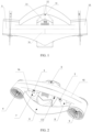
- a handheld underwater aircraft includes a battery compartment 12 and propellers, where there are at least two propellers, which are symmetrically arranged with respect to the battery compartment 12, and are connected to the battery compartment 12; and an axis of each of the propellers and an axis of the battery compartment 12 form an included angle.
- This embodiment has the beneficial effects that the propellers are symmetrically arranged with respect to the battery compartment 12, which can ensure the balance of the underwater aircraft and maintain the straight forward motion of the underwater aircraft; axes of the propellers and an axis of the battery compartment 12 are set to form non-parallel included angles, such that when the underwater aircraft is advancing in the water, the water coming out of the propeller has a certain angular deviation from the direction of motion of the underwater aircraft, and the water coming out of the propeller will not be sprayed on the face or body of a user against the direction of motion of the underwater aircraft and will not obstruct the line of sight or lose power; due to symmetrical arrangement of the propellers, component forces generated by the propellers in a direction of motion of a non-underwater aircraft offset each other out, so that the underwater aircraft maintains balanced and straight-forward motion; the arrangement that the axis of each of the propellers and the axis of the battery compartment 12 form an included angle leads to a very small natural loss, but avoids
- a handheld underwater aircraft includes a battery compartment 12 and propellers, where there are at least two propellers, which are symmetrically arranged with respect to the battery compartment 12, and are connected to the battery compartment 12; and an axis of each of the propellers and an axis of the battery compartment 12 form an included angle.
- the battery compartment 12 has a power supply, and the power supply is connected to the propellers through a circuit to provide energy to the propellers.
- propellers there are two propellers: a left propeller and a right propeller, and water inlet ends of the propellers are biased toward the battery compartment 12.
- there may be three propellers the three propellers are symmetrically arranged with respect to the battery compartment 12 through connecting rods respectively, and water inlet ends of the propellers are biased toward the battery compartment 12.
- there are four propellers two sides of the battery compartment 12 are each connected to two propellers, and water inlet ends of the propellers are biased toward the battery compartment 12.
- the propellers each include a propeller body and a propulsion cylinder.
- a left propeller body 5 is mounted in a propulsion cylinder 10 and a right propeller body 4 is mounted in a right propulsion cylinder 9.
- the two propellers and the battery compartment 12 can be connected by connecting rods.
- each of the propellers and the battery compartment 12 are connected by a buoyancy bridge, and the buoyancy bridge is provided with handles facilitating the holding by a user, the propeller and the battery compartment 12 are connected by the buoyancy bridge, and the buoyancy bridge also plays a role in increasing buoyancy; and the handles are arranged on the buoyancy bridge and facilitate the holding of the underwater aircraft by the user.
- the propellers are symmetrically arranged with respect to the battery compartment 12, which can ensure the balance of the present disclosure and maintain the straight-forward motion of the underwater aircraft;
- the axis of each of the propellers and the axis of the battery compartment 12 are set to have an included angle, such that when the underwater aircraft is advancing in the water, there is a certain included angle between the water coming out of the propeller and the direction of motion of the underwater aircraft, and the water coming out of the propeller will not be sprayed on the face or body of the user against the direction of motion of the underwater aircraft;
- due to the symmetrical arrangement of the propellers component forces generated by the propellers in the direction of motion of a non-underwater aircraft offset each other, so that the underwater aircraft maintained balanced and straight-forward motion;
- due to symmetrical arrangement of the propellers component forces generated by the propellers in a direction of motion of a non-underwater aircraft offset each other out, so that the underwater aircraft maintains balanced and straight-forward motion; the arrangement that the axis
- the included angle between the axis of the propeller and the axis of the battery compartment 12 is ⁇ , where ⁇ is greater than 0 degree and less than 45 degrees, and an optimal included angle is 5 degrees.
- the included angle between the propeller and the battery compartment 12 should not be too large; when the included angle is too large, a greater natural loss is caused when the component forces generated in the direction of motion of the non-underwater aircraft offset each other, resulting in waste of energy.
- the included angle ⁇ is preferably 0-10 degrees, and the optimal included angle ⁇ is 5 degrees.
- the included angle between the axis of the propeller and the axis of the battery compartment is 0-10 degrees, relative to when the included angle is greater than 10 degrees and less than 45 degrees, the energy consumption of the propeller is significantly reduced under the same speed of motion of the present disclosure; when the included angle between the propeller and the battery compartment 12 is 5 degrees, the natural loss is reasonably reduced, and more loss caused by the impact of the water on the human body is avoided, thereby improving thrust in use on the whole.
- the two propellers are connected by the buoyancy block 6, which can reduce resistance and increase buoyancy without adding an external floating block, thereby preventing an external floating block device from falling into the water, sinking to the bottom and being lost, reducing device costs, and reducing operation steps.
- an external floating block generally needs to be additionally added to improve buoyancy.
- the buoyancy block 6 is arranged in front of the battery compartment 12, and is a curved plate with a middle portion protruding forward; and the buoyancy block 6 is V-shaped as a whole, with a bent portion facing forward.
- the buoyancy block 6 is arranged in front of the battery compartment 12, and is the curved plate with the middle portion protruding forward, so that the buoyancy block 6 can function in the motion of the underwater aircraft in such a way that the protruding curved plate can reduce the resistance in advancing of the underwater aircraft.
- the buoyancy bridge includes an upper buoyancy plate 15 and a lower buoyancy plate 16 which are arranged in parallel, and both ends of the upper buoyancy plate 15 and both ends of the lower buoyancy plate 16 are connected to the two propellers respectively; an upper end of the battery compartment 12 is mounted on a middle portion of a lower surface of the upper buoyancy plate 15, and a lower end of the battery compartment is mounted on a middle portion of an upper surface of the lower buoyancy plate 16; and handles are symmetrically arranged on two sides of the battery compartment 12.
- the handles include a left handle 8 and a right handle 7, where an upper end of the handle is connected to the upper buoyancy plate 15, and a lower end of the handle is connected to the lower buoyancy plate 16; one of the handles is provided with a propeller switch 1, and the other handle is provided with a power switch 2.
- the upper buoyancy plate 15 and the lower buoyancy plate 16 which are arranged in parallel not only improve the buoyancy of the underwater aircraft on the whole, but also are attractive in appearance;
- the battery compartment 12 is mounted on middle portions of both the upper buoyancy plate 15 and the lower buoyancy plate 16 to ensure the balance of the underwater aircraft;
- the handles are symmetrically arranged on two sides of the battery compartment 12 to ensure the balance of the underwater aircraft;
- the upper end of the handle is connected to the upper buoyancy plate 15, and the lower end of the handle is connected to the lower buoyancy plate 16;
- the vertically-arranged handle facilitates holding by the user, making it more convenient and comfortable to hold the underwater aircraft;
- one of the handles is provided with the propeller switch 1, the other handle is provided with the power switch 2, and the propeller switch 1 and the power switch 2 are arranged on the handle, facilitating operation by the user.
- the buoyancy block 6, the upper buoyancy plate 15, the lower buoyancy plate, 16 and the handle each have a hollow structure.
- the hollow structure increases the buoyancy, reduces the weight of the underwater aircraft, and reduces costs.
- the hollow structure facilitates the wiring arrangement of a circuit.
- the propellers are each a variable speed propeller, a gear adjustment switch 13 for controlling the variable speed propeller is arranged on the handle or on a side wall of the battery compartment 12, and each of the variable speed propellers is correspondingly provided with one gear adjustment switch 13.
- the propellers are each a variable speed screw propeller, and the variable speed adjustment of the propeller pertains to the prior art.
- Those skilled in the art can directly purchase the variable speed propeller, or realize the variable speed of the propeller according to common knowledge in the art.
- the handheld underwater aircraft further includes a status display screen 3, where the status display screen 3 is arranged on an outer side wall of the battery compartment 12 to facilitate observation by the user, and a power supply in the battery compartment 12 and the propeller are in circuit connection with the status display screen 3; the status display screen 3 is configured to display parameter information of the power supply in the battery compartment 12 and the propeller.
- the handheld underwater aircraft further includes a pressure sensor 14 mounted on the lower front of the battery compartment 12, where the pressure sensor 14 is in circuit connection with the status display screen 3, and the status display screen 3 is configured to display detected data of the pressure sensor 14.
- the underwater aircraft is not provided with a buoyancy block 6, and the pressure sensor 14 is directly mounted on the lower front of the battery compartment 12.
- the underwater aircraft is provided with a buoyancy block 6, the front end of the battery compartment 12 is connected to the buoyancy block 6, and the pressure sensor 14 is directly mounted on the lower front of the battery compartment 12 and outside the buoyancy block 6 to facilitate the detection by the pressure sensor 14.
- the handheld underwater aircraft further includes an indicator lamp arranged on the status display screen 3.
- the pressure sensor 14 can effectively measure the speed of motion and underwater penetration, which can be displayed on the status display screen 3; when the depth reaches a certain value, the indicator lamp flashes to remind the user that he/she may reach a dangerous depth; and the status display screen 3 can display information of the underwater aircraft in real time.
- a lower side wall of the battery compartment is provided with an external slot 11 of a device, which is configured to mount an external device to the battery compartment, so that the underwater aircraft can carry other devices.
- the pressure sensor 14 is connected to a micro control unit (hereinafter referred to as MCU) through a flat cable, and the flat cable takes into account the transmission of power and data.
- MCU micro control unit
- the MCU sends a read instruction to the sensor to read internal data of the sensor and implements related calculations to obtain required data.
- sensors are carried on a control board in an underwater aircraft body, require no external circuit connection, and read and calculate data (such as electric quantity) in the MCU.
- the status display screen 3 is connected to the MCU of the control board through a flat cable, and the flat cable takes the transmission of power and data into account.
- the MCU controls the content displayed on the display, including but not limited to obtained sensor values (such as brand LOGO).
- the screw propeller is connected to the MCU through a propeller screw controller (the propeller screw controller is classified into a propeller screw category), a battery directly supplies electricity, and the propeller speed is directly controlled by a user input gear instruction obtained by the MCU (different gears can generate different speeds, resulting in different thrust).
- a propeller screw controller the propeller screw controller is classified into a propeller screw category
- a battery directly supplies electricity
- the propeller speed is directly controlled by a user input gear instruction obtained by the MCU (different gears can generate different speeds, resulting in different thrust).
- Speed control and on-off are controlled by different positions of a magnetic body outside a sealed compartment (battery compartment 12).
- a magnetic sensing element in the sealed compartment (battery compartment 12) can sense different positions of external magnetic bodies, thereby generating corresponding signals to the MCU, so as to enable a user to input on-off and speed control instructions to the underwater aircraft.
- the user controls the state and speed (input between the human and the aircraft) of the power switch 2 of the aircraft body through an external magnetic switch
- the display screen can display (controlled by the MCU) environmental information (acquired by the sensor under the control by the MCU) during the current operation and aircraft body state information (output between the human and the aircraft) to implement the interaction process between the human and the aircraft.
- underwater aircraft is waterproof and airtight, and those skilled in the art can perform sealing and waterproof settings according to actual needs without creative work, and descriptions are no longer made herein.
- This embodiment has the beneficial effects that this embodiment has all the beneficial effects of Embodiment 1; in addition, it has a fully enclosed buoyancy design; the buoyancy block 6, the upper buoyancy plate 15, and the lower buoyancy plate 16 are designed between the two propulsion cylinders, which can reduce resistance and increase buoyancy without adding an external floating block, thereby preventing the device from falling into the water, sinking to the bottom and being lost, reducing device costs, and reducing operation steps; the speed of the propeller can be adjusted through gears, and the pressure sensor 14 is arranged to effectively measure the speed of motion and underwater penetration, which can be displayed on the status display screen 3; when the depth reaches a certain value, the indicator lamp flashes to remind the user that he/she may reach a dangerous depth; and the status display screen 3 can display a working state of the device, such as voltage, current, speed, depth, and electric quantity, and an alarm will be made according to the flashing of the indicator lamp if there is an abnormality.
- the buoyancy block 6 the upper buoyancy plate 15, and the
- the handheld underwater aircraft of the present disclosure has significant beneficial effects.
- the structure of the present disclosure is described in detail above, and the impact of the included angle ⁇ between the axis of the propeller and the axis of the battery compartment 12 on the present disclosure is described below through test data.
- the included angle ⁇ has a certain influence on the working efficiency of the propeller. Therefore, in order to achieve a better working effect of the propeller, it is necessary to test the relationship between the included angle ⁇ and the working efficiency of the propeller.
- the distance between axes of the two propellers was 471.06 mm (this distance was the distance between the axes of the two propellers). Since a simplified model was adopted in the simulation experiment, in order to reduce the impact of the difference between the simplified model and an original model, the included angle ⁇ of the experimental test was 0 degree, 5 degree, and 10 degrees.
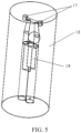
- the simplified model of the present disclosure used in the experiment is shown in a schematic diagram shown in FIG. 4 .
- Two dynamic domains are regions in a fairwater of the two propellers, and are two cone frustums having radiuses of 51.5 mm and 48.5 mm, respectively, and a height of 102 mm, which are compatible with the shape of the fairwater.
- the rotational speed of the dynamic domain 18 is 3000 rpm, and the rotation axis is the axis of the dynamic domain.
- the static domain 17 is a cylinder with a radius of 600 mm and a height of 2700 mm.
- a simulated human body 19 simulates the human body in the static domain 17 to hold the present disclosure with two hands.
- Initial conditions of the simulated flow field are set as follows:
- the water flow speed at an inlet surface is 1 m/s;
- the dynamic domain has a rotational speed of 3000 rpm, a rotation origin is a center coordinate of the dynamic domain, and the direction of the rotation axis is the same as the axial direction of the dynamic domain.
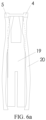
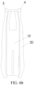
- Test results are shown in FIG. 6a , FIG. 6b , and FIG. 6c .
- the test results are that in FIG. 6a , when the included angle is 0 degree, water flow 20 coming out of the propeller overlaps with the simulated human body 19, that is, the water flow emitted by the propeller strikes on the human body, thereby affecting the speed in the flow domain; and when the included angle is 5 degrees or 10 degrees, the water flow emitted out of the propeller will not strike on the human body, but when the included angle is 10 degrees, the speed loss in the traveling direction is too large, so it is the most suitable when the propeller angle is 5 degrees.
- Blade stress (mean value of the left stress and the right stress) 42.2893 N 54.8333 N 40.0827 N
- the flow speed in the flow field obtained in the simulation is as follows: Included angle ⁇ 0 degree 5 degrees 10 degrees Average speed of the static domain 1.00181 m/s 1.5158 m/s 0.96897 m/s Average speed in the static domain in the y-axis direction (a negative value means opposite to the y-axis direction) -0.95222 m/s -1.42862 m/s -0.91488 m/s Maximum speed in the static domain 3.23066 m/s 4.27397 m/s 3.24015 m/s Maximum speed in the static domain in the y-axis direction (a negative value means opposite to the y-axis direction) -3.03575 m/s -4.00060 m/s -3.11736 m/s
- the optimal included angle ⁇ between the axis of the propeller and the axis of the battery compartment 12 is 5 degrees.
Landscapes
- Engineering & Computer Science (AREA)
- Mechanical Engineering (AREA)
- Ocean & Marine Engineering (AREA)
- Chemical & Material Sciences (AREA)
- Combustion & Propulsion (AREA)
- Health & Medical Sciences (AREA)
- General Health & Medical Sciences (AREA)
- Physical Education & Sports Medicine (AREA)
- Multimedia (AREA)
- Human Computer Interaction (AREA)
- Other Liquid Machine Or Engine Such As Wave Power Use (AREA)
Claims (7)
- Barquette portative, comprenant un compartiment à batteries (12) et des hélices, dans laquelle au moins deux hélices sont prévues, qui sont disposées de manière symétrique par rapport au compartiment à batteries (12) et reliées au compartiment à batteries (12) ; et un axe de chacune des hélices et un axe du compartiment à batteries (12) forment un angle inclus de non-zéro ;deux hélices sont prévues et les deux hélices sont reliées par un bloc flottant (6) ;les hélices et le compartiment à batteries (12) sont reliés par un pont flottant, etdes poignées (7, 8) sont disposées sur le pont flottant, le pont flottant comprend une plaque flottante supérieure (15) et une plaque flottante inférieure (16), qui sont disposées en parallèle,dans laquelle le bloc flottant (6), la plaque flottante supérieure (15), la plaque flottante inférieure (16) et les poignées (7, 8) présentent chacun une structure creuse.
- Barquette portative selon la revendication 1, dans laquelle une extrémité d'entrée d'eau de l'hélice est orientée vers le compartiment à batteries (12) et l'angle inclus est supérieur à 0 degré et inférieur à 45 degrés.
- Barquette portative selon la revendication 2, dans laquelle l'angle inclus est de 5 degrés.
- Barquette portative selon la revendication 1, dans laquelle le bloc flottant (6) est disposé devant le compartiment à batteries (12) et est une plaque incurvée ayant une partie centrale faisant saillie vers l'avant.
- Barquette portative selon la revendication 1, dans laquelle deux extrémités de la plaque flottante supérieure (15) et deux extrémités de la plaque flottante inférieure (16) sont reliées respectivement aux deux hélices ; une extrémité supérieure du compartiment à batteries (12) est montée sur une partie médiane d'une surface inférieure de la plaque flottante supérieure (15) et une extrémité inférieure du compartiment à batteries (12) est montée sur une partie médiane d'une surface supérieure de la plaque flottante inférieure (16) ; les poignées (7, 8) sont disposées de manière symétrique sur deux côtés du compartiment à batteries (12), une extrémité supérieure de chacune des poignées (7, 8) est reliée à la plaque flottante supérieure (15) et une extrémité inférieure de chacune des poignées (7, 8) est reliée à la plaque flottante inférieure (16) ; l'une des poignées (7, 8) est pourvue d'un commutateur de hélice (1) et l'autre poignée (7, 8) est pourvue d'un commutateur d'alimentation (2).
- Barquette portative selon la revendication 5, dans laquelle les hélices sont chacune une hélice à vitesse variable, un commutateur d'ajustement de vitesse pour commander l'hélice à vitesse variable est disposé sur la poignée (7, 8) ou sur une paroi latérale du compartiment à batteries (12), et chacune des hélices à vitesse variable est pourvue en conséquence d'un commutateur d'ajustement de vitesse (13).
- Barquette portative selon la revendication 1, comprenant en outre un écran d'affichage d'état (3), dans laquelle l'écran d'affichage d'état (3) est disposé sur une paroi latérale extérieure du compartiment à batteries (12), et une source d'électricité dans le compartiment à batteries (12) et les hélices sont électriquement connectée à l'écran d'affichage d'état (3) ; l'écran d'affichage d'état (3) est configuré pour afficher des informations sur des paramètres de la source d'électricité dans le compartiment à batteries (12) et des hélices ;comprenant en outre un capteur de pression (14) monté sur la face avant inférieure du compartiment à batteries (12), dans laquelle le capteur de pression (14) est électriquement connecté à l'écran d'affichage d'état (3) et l'écran d'affichage d'état (3) est configuré pour afficher des données détectées du capteur de pression (14) ; etcomprenant en outre un témoin lumineux disposé sur l'écran d'affichage d'état (3).
Applications Claiming Priority (3)
| Application Number | Priority Date | Filing Date | Title |
|---|---|---|---|
| CN201811229761.9A CN109260675A (zh) | 2018-10-22 | 2018-10-22 | 一种手持式水下飞行器 |
| CN201821709853.2U CN209060477U (zh) | 2018-10-22 | 2018-10-22 | 一种手持式水下飞行器 |
| PCT/CN2018/115068 WO2020082441A1 (fr) | 2018-10-22 | 2018-11-12 | Aéronef sous-marin portable |
Publications (4)
| Publication Number | Publication Date |
|---|---|
| EP3854463A1 EP3854463A1 (fr) | 2021-07-28 |
| EP3854463A4 EP3854463A4 (fr) | 2022-06-29 |
| EP3854463B1 true EP3854463B1 (fr) | 2023-09-13 |
| EP3854463C0 EP3854463C0 (fr) | 2023-09-13 |
Family
ID=70331221
Family Applications (1)
| Application Number | Title | Priority Date | Filing Date |
|---|---|---|---|
| EP18937589.2A Active EP3854463B1 (fr) | 2018-10-22 | 2018-11-12 | Sous-marin portable |
Country Status (3)
| Country | Link |
|---|---|
| US (1) | US11498649B2 (fr) |
| EP (1) | EP3854463B1 (fr) |
| WO (2) | WO2020082440A1 (fr) |
Families Citing this family (2)
| Publication number | Priority date | Publication date | Assignee | Title |
|---|---|---|---|---|
| CN113074909B (zh) * | 2021-05-18 | 2023-08-01 | 西安航空学院 | 一种空间多姿态入水实验装置 |
| US11767091B2 (en) * | 2021-11-16 | 2023-09-26 | Stallion Sport Limited | Collapsible underwater motive device |
Family Cites Families (16)
| Publication number | Priority date | Publication date | Assignee | Title |
|---|---|---|---|---|
| FR1582062A (fr) * | 1968-04-19 | 1969-09-26 | ||
| DE3523758A1 (de) * | 1985-07-03 | 1987-01-08 | Peter Jakusch | Wassersport - schwimmbeschleuniger |
| USD323808S (en) * | 1990-08-31 | 1992-02-11 | Desantis Albert | Underwater vehicle |
| US5158034A (en) * | 1992-02-24 | 1992-10-27 | Tontech International Co., Ltd. | Automatic swimming board |
| US8651811B2 (en) * | 2005-11-16 | 2014-02-18 | Hamilton Sundstrand | Control logic for a propeller system |
| SG174644A1 (en) * | 2010-03-22 | 2011-10-28 | Opcon Pte Ltd | A battery pack |
| US8651041B2 (en) * | 2012-05-07 | 2014-02-18 | Michael Myers | Personal underwater vehicle |
| CN203017687U (zh) * | 2012-11-29 | 2013-06-26 | 石家庄学院 | 助力游泳浮板 |
| CN203698636U (zh) | 2013-10-21 | 2014-07-09 | 侯功文 | 电动游泳艇 |
| CN106737703B (zh) * | 2016-11-22 | 2019-07-12 | 合肥中科艾帝尔机器人技术有限公司 | 基于水下救援机器人的水下救援方法 |
| CN107933860B (zh) * | 2017-11-23 | 2023-11-07 | 广东合一新材料研究院有限公司 | 一种水下移动搭载平台 |
| CN207917118U (zh) * | 2017-12-05 | 2018-09-28 | 台州新顺航游艇科技股份有限公司 | 一种智能无人水下救生艇 |
| CN207595225U (zh) * | 2017-12-15 | 2018-07-10 | 上海颖川佳固信息工程股份有限公司 | 一种检测港口码头的水下机器人 |
| CN207955998U (zh) * | 2018-01-08 | 2018-10-12 | 天津深之蓝海洋设备科技有限公司 | 水下助推装置 |
| CN108639236A (zh) * | 2018-05-15 | 2018-10-12 | 武汉理工大学 | 一种机翼型高速三体游艇结构 |
| CN208372405U (zh) | 2018-06-12 | 2019-01-15 | 博雅工道(北京)机器人科技有限公司 | 一种手持式水下飞行器 |
-
2018
- 2018-11-12 WO PCT/CN2018/115065 patent/WO2020082440A1/fr active Application Filing
- 2018-11-12 EP EP18937589.2A patent/EP3854463B1/fr active Active
- 2018-11-12 US US17/287,666 patent/US11498649B2/en active Active
- 2018-11-12 WO PCT/CN2018/115068 patent/WO2020082441A1/fr unknown
Also Published As
| Publication number | Publication date |
|---|---|
| WO2020082440A1 (fr) | 2020-04-30 |
| US20210347454A1 (en) | 2021-11-11 |
| WO2020082441A1 (fr) | 2020-04-30 |
| EP3854463C0 (fr) | 2023-09-13 |
| EP3854463A1 (fr) | 2021-07-28 |
| EP3854463A4 (fr) | 2022-06-29 |
| US11498649B2 (en) | 2022-11-15 |
Similar Documents
| Publication | Publication Date | Title |
|---|---|---|
| EP3854463B1 (fr) | Sous-marin portable | |
| EP3482802A1 (fr) | Dispositif destiné à vivre une simulation de réalité virtuelle dans un monde sous-marin | |
| US20110067157A1 (en) | Method and apparatus for Variable G force experience and creating immersive VR sensations | |
| CN208287445U (zh) | 一种基于虚拟现实技术的划船模拟装置 | |
| CN105791754A (zh) | 航空器的远距离操纵系统 | |
| CN108189978A (zh) | 一种一键返航冲浪板 | |
| CN107323630B (zh) | 一种冲浪和学习游泳的装置 | |
| CN208372405U (zh) | 一种手持式水下飞行器 | |
| CN110203359A (zh) | 仿豹鲂鮄鱼水下机器人 | |
| CN109260675A (zh) | 一种手持式水下飞行器 | |
| CN107310688A (zh) | 用于模拟风流载荷作用下做操纵运动的船模及其试验方法 | |
| CN209060477U (zh) | 一种手持式水下飞行器 | |
| CN203698631U (zh) | 一种用于儿童初学者学习游泳的救生装置 | |
| Yang et al. | Development of a bio-inspired transformable robotic fin | |
| CN106697224B (zh) | 一种船舶水下空化清洗装置 | |
| CN105292425A (zh) | 一种气压调节变刚度的柔性仿生机器鱼 | |
| JPH0471587A (ja) | 水上帆走および展示に適した帆船模型 | |
| CN207956002U (zh) | 无人遥控潜水器 | |
| CN208036541U (zh) | 一种具有自稳功能的抗风浪小船 | |
| CN111496803A (zh) | 太极推手机器人 | |
| CN206344976U (zh) | 一种水下教育类机器人 | |
| Yan et al. | Development of a Turtle-inspired Robot with Variable Stiffness Hydrofoils | |
| Luo et al. | Control system design and thrust analysis of an unmanned surface cleaning vessel with a novel pump-valve propulsion system | |
| Hu et al. | Modular design and motion control of reconfigurable robotic fish | |
| CN110215658A (zh) | 一种沉浸式海洋世界体验平台 |
Legal Events
| Date | Code | Title | Description |
|---|---|---|---|
| STAA | Information on the status of an ep patent application or granted ep patent |
Free format text: STATUS: THE INTERNATIONAL PUBLICATION HAS BEEN MADE |
|
| PUAI | Public reference made under article 153(3) epc to a published international application that has entered the european phase |
Free format text: ORIGINAL CODE: 0009012 |
|
| STAA | Information on the status of an ep patent application or granted ep patent |
Free format text: STATUS: REQUEST FOR EXAMINATION WAS MADE |
|
| 17P | Request for examination filed |
Effective date: 20210420 |
|
| AK | Designated contracting states |
Kind code of ref document: A1 Designated state(s): AL AT BE BG CH CY CZ DE DK EE ES FI FR GB GR HR HU IE IS IT LI LT LU LV MC MK MT NL NO PL PT RO RS SE SI SK SM TR |
|
| DAV | Request for validation of the european patent (deleted) | ||
| DAX | Request for extension of the european patent (deleted) | ||
| A4 | Supplementary search report drawn up and despatched |
Effective date: 20220531 |
|
| RIC1 | Information provided on ipc code assigned before grant |
Ipc: B63C 11/46 20060101ALI20220524BHEP Ipc: B63H 5/07 20060101ALI20220524BHEP Ipc: A63B 35/08 20060101AFI20220524BHEP |
|
| GRAP | Despatch of communication of intention to grant a patent |
Free format text: ORIGINAL CODE: EPIDOSNIGR1 |
|
| STAA | Information on the status of an ep patent application or granted ep patent |
Free format text: STATUS: GRANT OF PATENT IS INTENDED |
|
| INTG | Intention to grant announced |
Effective date: 20230612 |
|
| GRAS | Grant fee paid |
Free format text: ORIGINAL CODE: EPIDOSNIGR3 |
|
| GRAA | (expected) grant |
Free format text: ORIGINAL CODE: 0009210 |
|
| STAA | Information on the status of an ep patent application or granted ep patent |
Free format text: STATUS: THE PATENT HAS BEEN GRANTED |
|
| AK | Designated contracting states |
Kind code of ref document: B1 Designated state(s): AL AT BE BG CH CY CZ DE DK EE ES FI FR GB GR HR HU IE IS IT LI LT LU LV MC MK MT NL NO PL PT RO RS SE SI SK SM TR |
|
| RAP3 | Party data changed (applicant data changed or rights of an application transferred) |
Owner name: BOYA GONGDAO (BEIJING) ROBOT TECHNOLOGY CO., LTD. |
|
| REG | Reference to a national code |
Ref country code: CH Ref legal event code: EP |
|
| REG | Reference to a national code |
Ref country code: DE Ref legal event code: R096 Ref document number: 602018057764 Country of ref document: DE |
|
| REG | Reference to a national code |
Ref country code: IE Ref legal event code: FG4D |
|
| U01 | Request for unitary effect filed |
Effective date: 20230927 |
|
| U07 | Unitary effect registered |
Designated state(s): AT BE BG DE DK EE FI FR IT LT LU LV MT NL PT SE SI Effective date: 20231009 |
|
| U20 | Renewal fee paid [unitary effect] |
Year of fee payment: 6 Effective date: 20231130 |
|
| PG25 | Lapsed in a contracting state [announced via postgrant information from national office to epo] |
Ref country code: GR Free format text: LAPSE BECAUSE OF FAILURE TO SUBMIT A TRANSLATION OF THE DESCRIPTION OR TO PAY THE FEE WITHIN THE PRESCRIBED TIME-LIMIT Effective date: 20231214 |
|
| PG25 | Lapsed in a contracting state [announced via postgrant information from national office to epo] |
Ref country code: RS Free format text: LAPSE BECAUSE OF FAILURE TO SUBMIT A TRANSLATION OF THE DESCRIPTION OR TO PAY THE FEE WITHIN THE PRESCRIBED TIME-LIMIT Effective date: 20230913 Ref country code: NO Free format text: LAPSE BECAUSE OF FAILURE TO SUBMIT A TRANSLATION OF THE DESCRIPTION OR TO PAY THE FEE WITHIN THE PRESCRIBED TIME-LIMIT Effective date: 20231213 Ref country code: HR Free format text: LAPSE BECAUSE OF FAILURE TO SUBMIT A TRANSLATION OF THE DESCRIPTION OR TO PAY THE FEE WITHIN THE PRESCRIBED TIME-LIMIT Effective date: 20230913 Ref country code: GR Free format text: LAPSE BECAUSE OF FAILURE TO SUBMIT A TRANSLATION OF THE DESCRIPTION OR TO PAY THE FEE WITHIN THE PRESCRIBED TIME-LIMIT Effective date: 20231214 |
|
| PG25 | Lapsed in a contracting state [announced via postgrant information from national office to epo] |
Ref country code: IS Free format text: LAPSE BECAUSE OF FAILURE TO SUBMIT A TRANSLATION OF THE DESCRIPTION OR TO PAY THE FEE WITHIN THE PRESCRIBED TIME-LIMIT Effective date: 20240113 |
|
| PG25 | Lapsed in a contracting state [announced via postgrant information from national office to epo] |
Ref country code: ES Free format text: LAPSE BECAUSE OF FAILURE TO SUBMIT A TRANSLATION OF THE DESCRIPTION OR TO PAY THE FEE WITHIN THE PRESCRIBED TIME-LIMIT Effective date: 20230913 |
|
| PG25 | Lapsed in a contracting state [announced via postgrant information from national office to epo] |
Ref country code: SM Free format text: LAPSE BECAUSE OF FAILURE TO SUBMIT A TRANSLATION OF THE DESCRIPTION OR TO PAY THE FEE WITHIN THE PRESCRIBED TIME-LIMIT Effective date: 20230913 Ref country code: RO Free format text: LAPSE BECAUSE OF FAILURE TO SUBMIT A TRANSLATION OF THE DESCRIPTION OR TO PAY THE FEE WITHIN THE PRESCRIBED TIME-LIMIT Effective date: 20230913 Ref country code: IS Free format text: LAPSE BECAUSE OF FAILURE TO SUBMIT A TRANSLATION OF THE DESCRIPTION OR TO PAY THE FEE WITHIN THE PRESCRIBED TIME-LIMIT Effective date: 20240113 Ref country code: ES Free format text: LAPSE BECAUSE OF FAILURE TO SUBMIT A TRANSLATION OF THE DESCRIPTION OR TO PAY THE FEE WITHIN THE PRESCRIBED TIME-LIMIT Effective date: 20230913 Ref country code: CZ Free format text: LAPSE BECAUSE OF FAILURE TO SUBMIT A TRANSLATION OF THE DESCRIPTION OR TO PAY THE FEE WITHIN THE PRESCRIBED TIME-LIMIT Effective date: 20230913 Ref country code: SK Free format text: LAPSE BECAUSE OF FAILURE TO SUBMIT A TRANSLATION OF THE DESCRIPTION OR TO PAY THE FEE WITHIN THE PRESCRIBED TIME-LIMIT Effective date: 20230913 |