EP3854340A1 - Hilfsvorrichtung für die implantation einer knochenschraube in das knochenmedium eines lebewesens - Google Patents
Hilfsvorrichtung für die implantation einer knochenschraube in das knochenmedium eines lebewesens Download PDFInfo
- Publication number
- EP3854340A1 EP3854340A1 EP21315006.3A EP21315006A EP3854340A1 EP 3854340 A1 EP3854340 A1 EP 3854340A1 EP 21315006 A EP21315006 A EP 21315006A EP 3854340 A1 EP3854340 A1 EP 3854340A1
- Authority
- EP
- European Patent Office
- Prior art keywords
- mandrel rod
- rod
- barrel
- bone
- screw
- Prior art date
- Legal status (The legal status is an assumption and is not a legal conclusion. Google has not performed a legal analysis and makes no representation as to the accuracy of the status listed.)
- Pending
Links
Images

Classifications
-
- A—HUMAN NECESSITIES
- A61—MEDICAL OR VETERINARY SCIENCE; HYGIENE
- A61B—DIAGNOSIS; SURGERY; IDENTIFICATION
- A61B17/00—Surgical instruments, devices or methods, e.g. tourniquets
- A61B17/56—Surgical instruments or methods for treatment of bones or joints; Devices specially adapted therefor
- A61B17/58—Surgical instruments or methods for treatment of bones or joints; Devices specially adapted therefor for osteosynthesis, e.g. bone plates, screws, setting implements or the like
- A61B17/88—Osteosynthesis instruments; Methods or means for implanting or extracting internal or external fixation devices
- A61B17/8875—Screwdrivers, spanners or wrenches
- A61B17/8886—Screwdrivers, spanners or wrenches holding the screw head
-
- A—HUMAN NECESSITIES
- A61—MEDICAL OR VETERINARY SCIENCE; HYGIENE
- A61B—DIAGNOSIS; SURGERY; IDENTIFICATION
- A61B17/00—Surgical instruments, devices or methods, e.g. tourniquets
- A61B17/56—Surgical instruments or methods for treatment of bones or joints; Devices specially adapted therefor
- A61B17/58—Surgical instruments or methods for treatment of bones or joints; Devices specially adapted therefor for osteosynthesis, e.g. bone plates, screws, setting implements or the like
- A61B17/68—Internal fixation devices, including fasteners and spinal fixators, even if a part thereof projects from the skin
- A61B17/70—Spinal positioners or stabilisers ; Bone stabilisers comprising fluid filler in an implant
- A61B17/7074—Tools specially adapted for spinal fixation operations other than for bone removal or filler handling
- A61B17/7076—Tools specially adapted for spinal fixation operations other than for bone removal or filler handling for driving, positioning or assembling spinal clamps or bone anchors specially adapted for spinal fixation
- A61B17/7082—Tools specially adapted for spinal fixation operations other than for bone removal or filler handling for driving, positioning or assembling spinal clamps or bone anchors specially adapted for spinal fixation for driving, i.e. rotating, screws or screw parts specially adapted for spinal fixation, e.g. for driving polyaxial or tulip-headed screws
-
- A—HUMAN NECESSITIES
- A61—MEDICAL OR VETERINARY SCIENCE; HYGIENE
- A61B—DIAGNOSIS; SURGERY; IDENTIFICATION
- A61B17/00—Surgical instruments, devices or methods, e.g. tourniquets
- A61B17/56—Surgical instruments or methods for treatment of bones or joints; Devices specially adapted therefor
- A61B17/58—Surgical instruments or methods for treatment of bones or joints; Devices specially adapted therefor for osteosynthesis, e.g. bone plates, screws, setting implements or the like
- A61B17/88—Osteosynthesis instruments; Methods or means for implanting or extracting internal or external fixation devices
- A61B17/8875—Screwdrivers, spanners or wrenches
-
- A—HUMAN NECESSITIES
- A61—MEDICAL OR VETERINARY SCIENCE; HYGIENE
- A61B—DIAGNOSIS; SURGERY; IDENTIFICATION
- A61B34/00—Computer-aided surgery; Manipulators or robots specially adapted for use in surgery
- A61B34/30—Surgical robots
-
- A—HUMAN NECESSITIES
- A61—MEDICAL OR VETERINARY SCIENCE; HYGIENE
- A61B—DIAGNOSIS; SURGERY; IDENTIFICATION
- A61B34/00—Computer-aided surgery; Manipulators or robots specially adapted for use in surgery
- A61B34/20—Surgical navigation systems; Devices for tracking or guiding surgical instruments, e.g. for frameless stereotaxis
- A61B2034/2046—Tracking techniques
- A61B2034/2055—Optical tracking systems
-
- A—HUMAN NECESSITIES
- A61—MEDICAL OR VETERINARY SCIENCE; HYGIENE
- A61B—DIAGNOSIS; SURGERY; IDENTIFICATION
- A61B90/00—Instruments, implements or accessories specially adapted for surgery or diagnosis and not covered by any of the groups A61B1/00 - A61B50/00, e.g. for luxation treatment or for protecting wound edges
- A61B90/36—Image-producing devices or illumination devices not otherwise provided for
- A61B90/37—Surgical systems with images on a monitor during operation
- A61B2090/374—NMR or MRI
-
- A—HUMAN NECESSITIES
- A61—MEDICAL OR VETERINARY SCIENCE; HYGIENE
- A61B—DIAGNOSIS; SURGERY; IDENTIFICATION
- A61B90/00—Instruments, implements or accessories specially adapted for surgery or diagnosis and not covered by any of the groups A61B1/00 - A61B50/00, e.g. for luxation treatment or for protecting wound edges
- A61B90/36—Image-producing devices or illumination devices not otherwise provided for
- A61B90/37—Surgical systems with images on a monitor during operation
- A61B2090/376—Surgical systems with images on a monitor during operation using X-rays, e.g. fluoroscopy
- A61B2090/3762—Surgical systems with images on a monitor during operation using X-rays, e.g. fluoroscopy using computed tomography systems [CT]
Definitions
- the present invention relates to devices for assisting the implantation of bone screws into the bone medium of a living being, which find a particularly advantageous application in the field of spinal osteosynthesis, more particularly for the implantation of systems which allow the maintenance of two vertebrae, consecutive or not, one relative to the other with a view to performing a spinal arthrodesis with the aim, for example, of removing the cause of the pain generated by a fracture of the vertebrae or to avoid the risk of paralytic complication linked to this fracture or to treat a degenerative or tumor pathology of the spine.
- the object of the present invention is to provide a device for assisting the implantation of bone screws in the bone environment of a living being, which attempts to limit as much as possible the risks of such an implantation by allowing the most secure possible implantation, which is of the simplest and least expensive possible realization compared to the similar devices known of the prior art, while facilitating the work Practitioners.
- the present invention relates to a device for assisting the implantation of a bone screw in a bone medium, in accordance with at least one of the appended claims.
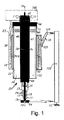
- the invention relates to a device for assisting the implantation of a bone screw 10 in a bone medium.
- Such a screw comprises a screw shank 11 defined along a screwing axis 12 between a proximal end 13 and a distal end 14; a bone thread 15 produced at the periphery of the screw shank 11, this bone thread having a pitch of determined value equal to Pa; a screw head 16 integral with the proximal end 13 of the screw shank, the distal end 14 of the screw shank having a configuration allowing it to penetrate by self-tapping into the bone medium.
- Such screws are well known in themselves.
- the device according to the invention comprises a barrel 20 defining a longitudinal axis 21, a cylindrical bushing 22 of revolution produced in the barrel 20 along the longitudinal axis 21, an internal thread 23 made on the wall of the passage 22, the internal thread 23 having a pitch of value Pa, and means 24 for fixing the barrel 20 to a reference point 25 linked to the bone medium Os.
- Mandrel rod 30 defined between a proximal end 31 and a distal end 32, the mandrel rod 30 having, on its lateral surface, at least one portion of a cylindrical surface of revolution substantially complementary to the bushing 22, a thread 33 carried by the portion of the cylindrical surface of revolution of the mandrel rod 30, the pitch of which is also of value Pa, so that the mandrel rod 30 is able to be screwed into the internal thread 23 of the barrel 20.
- the device further comprises means 35 for coupling the distal end 32 of the mandrel rod 30 with the screw head 16 so that the axis 12 of the screw rod 11 coincides with the longitudinal axis 21, and means 140 for controlling the rotation of the mandrel rod 30 relative to the barrel 20.
- the means 24 for fixing the barrel 20 to a reference point 25 they very preferably comprise an arm 124 or the like fixedly linked to the reference point 25, optionally articulated with a simple locking, and means 125 for securing the arm 124 to the barrel 20.
- the reference point 25 may consist of a point in the environment in which the patient is located who is to be treated as explained in the preamble of the description. This point can for example be linked, directly or indirectly, to the operating table on which the patient is immobilized.
- the device comprises a cylindrical through orifice 50 made in the mandrel rod 30, along the longitudinal axis 21, and a spindle 51 whose cross section is at most equal to the cross section of the through orifice 50, the spindle being suitable for be inserted by sliding in this through hole.
- Such a brooch is also known per se. It is often referred to by practitioners under the name “Kirschner pin”. These pins, usually stainless steel, sterilized, sharp, small diameter and smooth, are widely used in orthopedics to reduce fractures.
- the mandrel rod 30 has a side through window 70, figures 2 and 3 , produced in its wall, this lateral through-window 70 being able to connect the outside of the mandrel rod with the through-hole 50, the pin 51 then being able to be plugged into the through-hole 50 via this lateral through-window of the made of its natural elastic flexibility.
- the means 35 for coupling the distal end 32 of the mandrel rod 30 with the screw head 16 are very advantageously constituted by a through hole 40 made in the mandrel rod. 30, the through opening having an axis substantially coincident with the longitudinal axis 21
- the device then further comprises a connecting rod 41 defined between a proximal end 42 and a distal end 43, means 44 for rigidly and removably fixing the connecting rod 41 with the mandrel rod 30, and means for connecting to the mandrel. less rotating and removably the distal end 43 of the connecting rod 41 with the screw head 16, the through orifice 50 then being produced in the connecting rod 41 along the longitudinal axis 21.
- the means 44 for rigidly and removably fixing the connecting rod 41 with the mandrel rod 30 can be produced in many ways.
- they can consist of a collar or the like which encloses both the connecting rod 41 and the mandrel rod 30 and clips which connect the collar with these two rods respectively.
- the lateral through window 70 also passes through this connecting rod 41.
- the device comprises means 80 for fixing the spindle 51 in translation relative to the mandrel rod 30 (and the connecting rod 41 when it is present) after the spindle has been introduced into the orifice. crossing 50 via the side through window 70.
- These means 80 can be constituted, figure 2 , by a deformation of the proximal end of the pin in the form of a butt 81, and a lateral notch 82 made in the mandrel rod 30 (and the connecting rod when it is present) in a plane substantially perpendicular to axis 21, this notch opening into the lateral through window 70.
- the device comprises means for releasing the fixing of the spindle 51 after the mandrel rod 30 has been translated by a certain amount relative to the barrel 20, to ensure the screwing of the spindle. bone screw 10 in a bone like that of a vertebra.
- the butt 81 may be subjected to the action of a return spring, such as for example an elastic strip, to ensure its translation more certain in the notch 82 to bring it back into the slot. the axis of the through-hole 50.
- a return spring such as for example an elastic strip
- mandrel rod 30 operates as follows, specifying that, by “mandrel rod 30”, it should be understood for the description of this operation, either the mandrel rod 30 alone or in combination with the connecting rod 41 when it is used. is present, since the latter is integral with the mandrel rod.
- the pin 51 is engaged in the mandrel rod 30 via the through window 70, but with the butt 81 inserted by rotation in the lateral notch 82 so as to be locked in the outward emergent position, the distal end of the pin protruding by a certain amount the distal end 14 of the screw 10, figure 3 , for example 15 mm for a bone such as a vertebra.
- the device is then actuated and the rotation of the mandrel rod 30 with respect to the barrel 20 takes place so that the bone screw 10 first comes into contact with the bone, while the pin has already entered the bone. bone of the vertebra of this amount of 15 mm, and screws into the bone following the pin already implanted in the bone.
- the emerging stick 81 comes, after a determined path of the mandrel rod, abut against the stop present at the end surface 85 of the barrel 20.
- the stick 81 then disengages from the lateral notch 82 under the effect of the rotation of the mandrel rod 30, this disengagement possibly being favored by the elastic strip if it is present, and the stick is found in the axis of the through window 70, and therefore also of the breakthrough 50.
- the rotation of the mandrel rod 30 is maintained, which has the effect of advancing the screw by screwing into the bone, while the pin 51 remains stationary on its axis since it is blocked by the barrel 20 and does not penetrate further into the bone. 'bone, hence the safety of not reaching vital organs of the patient, the position of the pin 51 can moreover be verified, for additional safety, via radiological guidance.
- the mandrel rod 30 consists of at least two shells 91, 92 capable of being fixedly assembled with one another but while leaving a space between two opposite longitudinal edges of these two shells, so that this space constitutes the side through window 70 defined above.
- One of the advantages of this embodiment is that it allows the device to be used with screws of different diameters without having to change all of the constituent elements of the device.
- the means for at least rotating and removably connecting the distal end 43 of the connecting rod 41 with the screw head 16 consist of snap-on / snap-off means, the embodiment of which is well known in it. even those skilled in the art, for example of the elastic stress ratchet type.
- the device further comprises means for determining the position of the mandrel rod 30 relative to the barrel 20.
- These means are for example constituted by a ring 60 integral with the periphery of the mandrel rod 30 and comprising fiduciary benchmarks to be able to cooperate with a triangulation system.
- the mandrel rod 30 is then positioned by a navigation system making the fiduciary marks detected by an external triangulation system correspond to a database of 3D imaging of the patient (scanner, MRI).
- the diameter of the mandrel rod 30 ( its thread 33 not included) is greater than the diameter of the fictitious cylinder enveloping the thread 15 of the screw rod 11.
- the length of the mandrel rod 30 is greater than the length of the barrel 20.
- the structure of this device also makes it possible to adapt it to each type of screw head, on condition, however, that the screws have the same screw pitch Pa as those of the internal thread 23 and of the thread 33, by interchanging only the rod. link 41, without having to change the mandrel rod 30.
Landscapes
- Health & Medical Sciences (AREA)
- Orthopedic Medicine & Surgery (AREA)
- Surgery (AREA)
- Life Sciences & Earth Sciences (AREA)
- Neurology (AREA)
- Engineering & Computer Science (AREA)
- Medical Informatics (AREA)
- Heart & Thoracic Surgery (AREA)
- Biomedical Technology (AREA)
- Molecular Biology (AREA)
- Animal Behavior & Ethology (AREA)
- General Health & Medical Sciences (AREA)
- Public Health (AREA)
- Veterinary Medicine (AREA)
- Nuclear Medicine, Radiotherapy & Molecular Imaging (AREA)
- Robotics (AREA)
- Surgical Instruments (AREA)
Applications Claiming Priority (1)
| Application Number | Priority Date | Filing Date | Title |
|---|---|---|---|
| FR2000736A FR3106483B1 (fr) | 2020-01-25 | 2020-01-25 | Dispositif d’aide à l’implantation d’une vis osseuse dans le milieu osseux d’un être vivant. |
Publications (1)
| Publication Number | Publication Date |
|---|---|
| EP3854340A1 true EP3854340A1 (de) | 2021-07-28 |
Family
ID=70804705
Family Applications (1)
| Application Number | Title | Priority Date | Filing Date |
|---|---|---|---|
| EP21315006.3A Pending EP3854340A1 (de) | 2020-01-25 | 2021-01-16 | Hilfsvorrichtung für die implantation einer knochenschraube in das knochenmedium eines lebewesens |
Country Status (2)
| Country | Link |
|---|---|
| EP (1) | EP3854340A1 (de) |
| FR (1) | FR3106483B1 (de) |
Citations (5)
| Publication number | Priority date | Publication date | Assignee | Title |
|---|---|---|---|---|
| US20070162046A1 (en) * | 2004-01-29 | 2007-07-12 | Vandewalle Mark V | Method and apparatus for retaining a guide wire |
| US20080269768A1 (en) | 2007-04-10 | 2008-10-30 | Stryker Trauma Sa | Bone screw holding device |
| US20140094822A1 (en) | 2012-09-21 | 2014-04-03 | Atlas Spine, Inc. | Minimally invasive spine surgery instruments: guide wire handle with a guide wire locking mechanism |
| US20180147018A1 (en) | 2012-06-21 | 2018-05-31 | Globus Medical, Inc. | Surgical robotic automation with tracking markers and controlled tool advancement |
| US20190090966A1 (en) * | 2017-05-10 | 2019-03-28 | Mako Surgical Corp. | Robotic spine surgery system and methods |
-
2020
- 2020-01-25 FR FR2000736A patent/FR3106483B1/fr active Active
-
2021
- 2021-01-16 EP EP21315006.3A patent/EP3854340A1/de active Pending
Patent Citations (5)
| Publication number | Priority date | Publication date | Assignee | Title |
|---|---|---|---|---|
| US20070162046A1 (en) * | 2004-01-29 | 2007-07-12 | Vandewalle Mark V | Method and apparatus for retaining a guide wire |
| US20080269768A1 (en) | 2007-04-10 | 2008-10-30 | Stryker Trauma Sa | Bone screw holding device |
| US20180147018A1 (en) | 2012-06-21 | 2018-05-31 | Globus Medical, Inc. | Surgical robotic automation with tracking markers and controlled tool advancement |
| US20140094822A1 (en) | 2012-09-21 | 2014-04-03 | Atlas Spine, Inc. | Minimally invasive spine surgery instruments: guide wire handle with a guide wire locking mechanism |
| US20190090966A1 (en) * | 2017-05-10 | 2019-03-28 | Mako Surgical Corp. | Robotic spine surgery system and methods |
Also Published As
| Publication number | Publication date |
|---|---|
| FR3106483A1 (fr) | 2021-07-30 |
| FR3106483B1 (fr) | 2023-06-16 |
Similar Documents
| Publication | Publication Date | Title |
|---|---|---|
| EP1119305B1 (de) | Spinales osteosynthesesystem mit verbesserter stabilität | |
| EP2393441B1 (de) | Osteosynthese- und arthrodese-schraube | |
| EP0825835B1 (de) | Implantierbare osteosynthesevorrichtung | |
| CA2330705A1 (fr) | Systeme d'osteosynthese rachidienne pour une fixation anterieure | |
| CA2160875A1 (fr) | Agrafe d'osteosynthese et materiel ancillaire pour sa pose | |
| EP1152704A1 (de) | Distraktions/verkürzungsvorrichtung für ein system zur wirbelsäulenosteosynthese | |
| WO2006003316A1 (fr) | Broche de fixation d'un support sur un os | |
| EP0180532B1 (de) | Koaptor für Frakturen des Oberschenkelhalses und dergleichen | |
| FR2642642A1 (fr) | Implant d'osteosynthese posterieure rachidienne | |
| FR2668360A1 (fr) | Dispositif pour l'osteosynthese d'une fracture haute ou etagee du femur. | |
| EP2730243B1 (de) | Osteosynthesevorrichtung für die Behandlung von Knochenbrüchen des Oberschenkelhalses. | |
| WO2003032849A1 (fr) | Systeme pour maintenir au moins deux vertebres l'une par rapport a l'autre pour realiser une osteosynthese rachidienne | |
| FR2720261A1 (fr) | Implant pour dispositif d'ostéosynthèse. | |
| EP3854340A1 (de) | Hilfsvorrichtung für die implantation einer knochenschraube in das knochenmedium eines lebewesens | |
| WO1996039971A1 (fr) | Bague d'osteosynthese utilisable en combinaison avec une broche ou une vis, et ancillaire pour sa mise en compression | |
| FR2712173A1 (fr) | Dispositif pour la réduction de fractures. | |
| WO2021028636A2 (fr) | Implant intramédullaire pour ostéotomie transversale | |
| WO2000040164A1 (fr) | Vis d'osteosynthese autocompressive pour la chirurgie de petits os | |
| WO2009053540A1 (fr) | Vis compressive a tete filetee pour osteosynthese | |
| FR3112071A1 (fr) | Dispositif pour visser une vis pédiculaire | |
| FR3008301A1 (fr) | Dispositif pour la distraction d'un tissu | |
| FR3076199A1 (fr) | Systeme pour relier deux portions d'os entre elles quand l'une doit se deplacer par rapport a l'autre | |
| FR2668920A1 (fr) | Implant pour os fracture et gabarit de pose. | |
| EP3282985A1 (de) | Schrauben-/schraubendrehersystem für knöchernes medium | |
| WO2014191663A1 (fr) | Dispositif d'ostéosynthèse à vis cervico-céphalique |
Legal Events
| Date | Code | Title | Description |
|---|---|---|---|
| PUAI | Public reference made under article 153(3) epc to a published international application that has entered the european phase |
Free format text: ORIGINAL CODE: 0009012 |
|
| STAA | Information on the status of an ep patent application or granted ep patent |
Free format text: STATUS: THE APPLICATION HAS BEEN PUBLISHED |
|
| AK | Designated contracting states |
Kind code of ref document: A1 Designated state(s): AL AT BE BG CH CY CZ DE DK EE ES FI FR GB GR HR HU IE IS IT LI LT LU LV MC MK MT NL NO PL PT RO RS SE SI SK SM TR |
|
| STAA | Information on the status of an ep patent application or granted ep patent |
Free format text: STATUS: REQUEST FOR EXAMINATION WAS MADE |
|
| 17P | Request for examination filed |
Effective date: 20211006 |