EP3853052B1 - Système de stores comprenant un arbre d'enroulement à tube ondulé - Google Patents
Système de stores comprenant un arbre d'enroulement à tube ondulé Download PDFInfo
- Publication number
- EP3853052B1 EP3853052B1 EP19749643.3A EP19749643A EP3853052B1 EP 3853052 B1 EP3853052 B1 EP 3853052B1 EP 19749643 A EP19749643 A EP 19749643A EP 3853052 B1 EP3853052 B1 EP 3853052B1
- Authority
- EP
- European Patent Office
- Prior art keywords
- roller blind
- corrugated tube
- tube
- corrugated
- coupling
- Prior art date
- Legal status (The legal status is an assumption and is not a legal conclusion. Google has not performed a legal analysis and makes no representation as to the accuracy of the status listed.)
- Active
Links
- 238000004804 winding Methods 0.000 title claims description 25
- 230000008878 coupling Effects 0.000 claims description 27
- 238000010168 coupling process Methods 0.000 claims description 27
- 238000005859 coupling reaction Methods 0.000 claims description 27
- 238000005253 cladding Methods 0.000 description 20
- 238000005538 encapsulation Methods 0.000 description 12
- 238000007765 extrusion coating Methods 0.000 description 7
- 239000000463 material Substances 0.000 description 4
- 238000000034 method Methods 0.000 description 3
- 238000005520 cutting process Methods 0.000 description 2
- 239000004744 fabric Substances 0.000 description 2
- 239000011521 glass Substances 0.000 description 2
- 238000000071 blow moulding Methods 0.000 description 1
- 239000011248 coating agent Substances 0.000 description 1
- 238000000576 coating method Methods 0.000 description 1
- 238000001125 extrusion Methods 0.000 description 1
- 238000009434 installation Methods 0.000 description 1
- 238000004519 manufacturing process Methods 0.000 description 1
- 238000000465 moulding Methods 0.000 description 1
- 230000002093 peripheral effect Effects 0.000 description 1
- 230000036316 preload Effects 0.000 description 1
- 238000004080 punching Methods 0.000 description 1
- 238000007493 shaping process Methods 0.000 description 1
Images


Classifications
-
- B—PERFORMING OPERATIONS; TRANSPORTING
- B60—VEHICLES IN GENERAL
- B60J—WINDOWS, WINDSCREENS, NON-FIXED ROOFS, DOORS, OR SIMILAR DEVICES FOR VEHICLES; REMOVABLE EXTERNAL PROTECTIVE COVERINGS SPECIALLY ADAPTED FOR VEHICLES
- B60J1/00—Windows; Windscreens; Accessories therefor
- B60J1/20—Accessories, e.g. wind deflectors, blinds
- B60J1/2011—Blinds; curtains or screens reducing heat or light intensity
- B60J1/2013—Roller blinds
- B60J1/2036—Roller blinds characterised by structural elements
- B60J1/205—Winding tubes, e.g. telescopic tubes or conically shaped tubes
-
- B—PERFORMING OPERATIONS; TRANSPORTING
- B60—VEHICLES IN GENERAL
- B60J—WINDOWS, WINDSCREENS, NON-FIXED ROOFS, DOORS, OR SIMILAR DEVICES FOR VEHICLES; REMOVABLE EXTERNAL PROTECTIVE COVERINGS SPECIALLY ADAPTED FOR VEHICLES
- B60J7/00—Non-fixed roofs; Roofs with movable panels, e.g. rotary sunroofs
- B60J7/0007—Non-fixed roofs; Roofs with movable panels, e.g. rotary sunroofs moveable head-liners, screens, curtains or blinds for ceilings
- B60J7/0015—Non-fixed roofs; Roofs with movable panels, e.g. rotary sunroofs moveable head-liners, screens, curtains or blinds for ceilings roller blind
Definitions
- the invention relates to a roller blind arrangement for a motor vehicle with the features of the preamble of patent claim 1.
- roller blind arrangement is known from practice and is used in a motor vehicle, for example, to shade a transparent roof section, which can be formed by a glass cover of a sliding roof arrangement or by a fixed glass roof element.
- the roller blind arrangement comprises an opaque roller blind web that can be wound onto a winding shaft or unwound from the winding shaft in order to shade the corresponding transparent roof section.
- the winding shaft can be curved and, for this purpose, can comprise a curved, vehicle-fixed bearing strut, which is encompassed by a flexible sleeve tube arrangement, to which the roller blind web is connected via an edge extending in the transverse direction of the roller blind.
- the cladding tube arrangement comprises a cladding tube element forming a central section, which is designed as a corrugated tube and is connected at each of its ends to a bearing bush, via which the cladding tube arrangement is rotatably mounted on the bearing strut fixed to the vehicle.
- the roller blind web can be provided at its edges arranged on both sides with respect to a vertical longitudinal center plane of the roller blind with a guide strip, which is guided in a guide rail fixed to the vehicle and is fastened to one of the bearing bushes.
- the winding shaft comprises a winding spring, which prestresses the cladding tube arrangement together with the bearing bushes in the winding direction.
- roller blind arrangement for a sunroof system of a motor vehicle.
- This roller blind arrangement comprises a roller blind and a winding shaft onto which the roller blind can be wound or from which the roller blind can be unwound.
- the winding shaft comprises a flexible casing tube arrangement through which a bearing strut fixed to the vehicle passes.
- the cladding tube arrangement comprises a corrugated tube on which corrugated tube ribs are formed, which are separated from one another by corrugation troughs.
- the invention is based on the object of creating a roller blind arrangement formed according to the generic type mentioned in the introduction, in which the risk of jumps in the diameter of the roller blind roll formed on the winding shaft is minimized.
- the corrugated tube which is preferably made of plastic, is therefore provided at both ends with a coupling extrusion coating, via which a connection of the cladding tube arrangement to bearing bushes is possible.
- the coupling extrusions each have an outside diameter that corresponds to the maximum outside diameter of the corrugated tube.
- the corrugations or ribs of the corrugated tube thus have a height or a diameter that corresponds to the outside diameter of the coupling encapsulation.
- the corrugation crests of the ribs are thus aligned with the peripheral surface of the coupling encapsulation, which in particular follows a cylindrical surface.
- the roller blind roll formed on the winding shaft or the duct arrangement can be guided smoothly and without jumps in diameter up to the bearing bushes arranged on both sides. This minimizes the risk of waves and creases forming on the roller blind.
- the design of the cladding tube arrangement according to the invention also eliminates additional material and process costs for measures that counteract jumps in diameter.
- the corrugated tube itself whose ribs or corrugations have an outside diameter that corresponds to the outside diameter of the coupling extrusion coating, can be made very torsionally rigid. At the same time, the flexing work to be applied when actuating the winding shaft can be reduced.
- the high torsional rigidity leads to low plastic deformations in the area of the cladding tube arrangement.
- the low flexing work in turn leads to a low hysteresis of a coil spring, which prestresses the cladding tube arrangement in the winding direction of the roller blind.
- this can lead to an improved function of the roller blind arrangement in the case of long and/or wide roller blind webs that are subjected to a high spring preload.
- the corrugated tube has a cylindrical area at each of its ends, which is overlapped by the relevant coupling encapsulation and thus forms the interface for the coupling encapsulation.
- the outside diameter of the cylindrical connecting piece corresponds in particular to the outside diameter of the corrugated pipe in the region of the corrugated pipe valleys and is in any case smaller than that of the corrugated pipe ribs.
- the corrugated pipe has at least one recess in each of its end sections, which is filled by the relevant coupling encapsulation and thus forms an anchor point for the plastic of the coupling encapsulation.
- the recess in a special embodiment of the roller blind arrangement according to the invention extends through at least one corrugated pipe rib, so that the recess and at least one corrugated trough of the corrugated pipe are filled by the coupling overmoulding.
- the recess can be designed as a longitudinal slot or longitudinal groove.
- the plastic of the coupling extrusion coating can flow through the recess into at least one of the corrugation troughs of the corrugated tube and be distributed in the circumferential direction in the corrugation troughs.
- the coupling encapsulation can also flow on the inside of the corrugated pipe into depressions corresponding to the corrugated pipe ribs, so that a stable connection of the relevant coupling encapsulation to the corrugated pipe is ensured.
- the recess can be punched out directly by appropriate design of the tool. Only one tool stroke is required for cutting to length and for forming the recess.
- the corrugated tube has two recesses in at least one of its two front end sections, which are offset by 180° relative to the axis of the corrugated tube.
- these two recesses can also be formed in one stroke, since they lie one above the other in the punching direction.
- FIG 1 a vehicle roof 10 of a passenger car, otherwise not shown in detail, is shown, which has a roof cutout 12, which can be closed or at least partially released by means of a transparent cover element, not shown in detail here.
- the vehicle roof 10 comprises a shade arrangement 14 as a shading element for the roof opening 12, which has a shade web 16 made of a foldable or windable, opaque material.
- the roller blind 16 is provided at its front edge, which extends in the transverse direction of the roof, with a pull bow 18 which represents an actuating element of the roller blind arrangement 14 .
- the roller blind 16 is connected to a winding shaft 20, which also extends in the transverse direction of the roof.
- the winding shaft 20 shown in more detail is curved and thus follows a curvature of the vehicle roof 10. This is achieved in that the winding shaft 20 has a curved, vehicle-fixed bearing strut 22, which is connected on both sides to a vehicle-fixed bearing element 24A or 24B in relation to a vertical longitudinal center plane of the roof is.
- the bearing elements 24A and 24B are each arranged at a rear end of a respective guide rail 26A or 26B, which extends in the longitudinal direction of the roof or in the direction of extension of the roller blind 16 and in which a respective lateral edge of the roller blind 16 is guided via a guide band 28A or 28B is.
- the winding shaft 20 also includes a flexible casing tube arrangement 30 through which the bearing strut 22 extends.
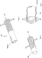
- the cladding tube arrangement 30 in turn comprises a corrugated tube 32 as a flexible cladding tube element, which is designed as a plastic vacuum molded part and which is provided at its ends arranged on both sides with respect to the vertical longitudinal center plane of the roof with a coupling encapsulation 34A or 34B made of plastic.
- the cladding tube arrangement 30 is connected on both sides to a bearing bush 36A or 36B via the coupling extrusion coating 34A and 34B and is thus rotatably mounted with its ends on the bearing strut 22 or the bearing journals 38A and 38B of the same.
- the corrugated pipe 32 comprises a multiplicity of annular collar-like corrugated pipe ribs 40 along its extent, which are separated from one another by corrugation troughs 42 and form a cylindrical annular surface.
- the corrugated tube 32 is provided on both sides with two axial, slot-like recesses 44 which are offset from one another by 180° in the circumferential direction and which reach through three corrugated tube ribs 40 .
- the coupling encapsulation 34A or 34B fills the recess 44 and the first three wave troughs 42 which adjoin the recess 44 .
- the outer diameter of the coupler overmold 34A or 34B corresponds to the outer diameter of the corrugated pipe ribs 40, so that the coupler overmolds 34A and 34B together with the adjacent corrugated pipe ribs 40 each form a continuous cylindrical surface and the roller blind roll of the roller blind web 16 on the winding shaft 20 without jumps in diameter up to the bearing bushes 36A and 36B, which are non-rotatably connected to the coupling extrusion coatings 34A and 34B.
- FIGS Figures 5 to 7 An alternative embodiment of a duct assembly 30' is shown which differs from the duct assembly of FIGS Figures 3 and 4 differs in that it is formed from a corrugated tube 32', to whose outermost corrugated tube ribs 40 in the end regions a cylindrical region or connecting piece 48 is connected, the outer diameter of which corresponds to the outer diameter of the corrugated tube 32' in the region of the corrugation troughs 42.
- the cylindrical connecting pieces 48 are each overlapped by a plastic encapsulation 34A or 34B, the outside diameter of which corresponds to the outside diameter of the corrugated tube ribs 40 .
- the cladding tube assembly 30 according to the cladding tube according to Figures 3 and 4 up to the outer end faces of the coupling extrusion coatings 34A and 34B, ie apart from the wave troughs 42, a constant outer diameter throughout.
Claims (6)
- Ensemble de store pour un véhicule automobile, l'ensemble de store comprenant un lé de store (16) et un arbre d'enroulement (20) sur lequel le lé de store (16) peut être enroulé ou sur lequel le lé de store (16) peut être déroulé et qui comprend un ensemble de tube enveloppe (30, 30') flexible qui est pénétré par une barre de support (22) solidaire du véhicule et qui comprend un tube ondulé (32, 32') comme élément de tube enveloppe, des nervures de tube ondulé (40) étant formées sur le tube ondulé (32, 32') et étant séparées l'une de l'autre par des creux (42), caractérisé en ce que le tube ondulé (32, 32') a un surmoulage de liaison (34A, 34B) à chacune de ses deux extrémités, chaque surmoulage de liaison (34A, 34B) étant lié à un coussinet (36A, 36B) respectif et ayant un diamètre extérieur qui correspond au diamètre extérieur maximal du tube ondulé (32, 32').
- Ensemble de store selon la revendication 1, caractérisé en ce que le tube ondulé (32') a une partie cylindrique à chacune de ses extrémités, chaque partie cylindrique étant couverte du surmoulage de liaison (34A, 34B) respectif.
- Ensemble de store selon la revendication 1 ou 2, caractérisé en ce que le tube ondulé (32) a au moins un évidement (44) dans chacune de ses parties d'extrémité, chaque évidement (44) étant rempli du surmoulage de liaison (34A, 34B) respectif.
- Ensemble de store selon la revendication 3, caractérisé en ce que l'évidement (44) s'étend à travers au moins une nervure de tube ondulé (40) de sorte que l'évidement (44) et au moins un creux (42) du tube ondulé (32) sont remplis du surmoulage de liaison (34A, 34B).
- Ensemble de store selon la revendication 3 ou 4, caractérisé en ce que l'évidement (40) est une fente longitudinale ou une rainure longitudinale.
- Ensemble de store selon l'une quelconque des revendications 3 à 5, caractérisé en ce que le tube ondulé (32) a deux évidements (44) dans au moins une de ses parties d'extrémité, les évidements (44) étant décalés l'un de l'autre par 180° par rapport à l'axe du tube ondulé (32).
Applications Claiming Priority (2)
| Application Number | Priority Date | Filing Date | Title |
|---|---|---|---|
| DE102018123280.2A DE102018123280A1 (de) | 2018-09-21 | 2018-09-21 | Rolloanordnung mit Wellrohrwickelwelle |
| PCT/EP2019/070188 WO2020057814A1 (fr) | 2018-09-21 | 2019-07-26 | Système de stores comprenant un arbre d'enroulement à tube ondulé |
Publications (2)
| Publication Number | Publication Date |
|---|---|
| EP3853052A1 EP3853052A1 (fr) | 2021-07-28 |
| EP3853052B1 true EP3853052B1 (fr) | 2022-10-12 |
Family
ID=67544194
Family Applications (1)
| Application Number | Title | Priority Date | Filing Date |
|---|---|---|---|
| EP19749643.3A Active EP3853052B1 (fr) | 2018-09-21 | 2019-07-26 | Système de stores comprenant un arbre d'enroulement à tube ondulé |
Country Status (5)
| Country | Link |
|---|---|
| US (1) | US11358442B2 (fr) |
| EP (1) | EP3853052B1 (fr) |
| CN (1) | CN112714704B (fr) |
| DE (1) | DE102018123280A1 (fr) |
| WO (1) | WO2020057814A1 (fr) |
Families Citing this family (2)
| Publication number | Priority date | Publication date | Assignee | Title |
|---|---|---|---|---|
| DE102017119767A1 (de) * | 2017-08-29 | 2019-02-28 | Webasto SE | Rolloanordnung mit Wickelwellenhüllrohr |
| CN113879082B (zh) * | 2021-10-15 | 2022-07-19 | 福耀玻璃工业集团股份有限公司 | 卷轴、卷帘组件、透光组件及车辆 |
Family Cites Families (14)
| Publication number | Priority date | Publication date | Assignee | Title |
|---|---|---|---|---|
| JP3749607B2 (ja) * | 1997-11-27 | 2006-03-01 | カルソニックカンセイ株式会社 | 車両用空調装置の冷媒配管と締結方法 |
| NZ504541A (en) * | 1998-01-13 | 2000-12-22 | Formway Furniture Ltd | A table assembly with extensible modesty screen such that as top of table is adjusted vertically screen maintains privacy to user |
| DE102005032043C5 (de) | 2005-07-08 | 2015-04-16 | Webasto Ag | Rollovorrichtung für ein Kraftfahrzeug |
| US20080216970A1 (en) * | 2007-03-08 | 2008-09-11 | Macauto Industrial Co., Ltd. | Sunshade assembly suitable for an arcuate window |
| FR2945091B1 (fr) * | 2009-04-30 | 2011-05-13 | Somfy Sas | Dispositif de transmission viscoelastique d'un actionneur d'un volet roulant |
| KR101107332B1 (ko) * | 2010-02-03 | 2012-01-20 | 동아금속주름관(주) | 주름관 연결구가 결합된 주름관 및 주름관 연결구와 주름관의 결합방법 |
| EP2529965B1 (fr) * | 2011-06-01 | 2014-03-12 | Roof Systems Germany GmbH | Store à enrouleur pour système de toit coulissant |
| JP6018784B2 (ja) * | 2012-04-17 | 2016-11-02 | ベバスト ジャパン株式会社 | ロールシェード装置 |
| DE102013102630B4 (de) | 2013-03-14 | 2023-02-02 | Webasto SE | Rolloanordnung mit Wickelwelle |
| WO2015042289A1 (fr) * | 2013-09-18 | 2015-03-26 | Lutron Electronics Co., Inc. | Système de traitement à fenêtre motorisée silencieuse |
| CN205078934U (zh) * | 2015-11-10 | 2016-03-09 | 高明芳 | 一种大口径的内梯口电热熔承插式钢带波纹管 |
| CN108533851A (zh) | 2017-03-06 | 2018-09-14 | 新昌县四通机电有限公司 | 减震管 |
| JP2019018728A (ja) * | 2017-07-18 | 2019-02-07 | アイシン精機株式会社 | ロールシェード装置 |
| DE102017119767A1 (de) * | 2017-08-29 | 2019-02-28 | Webasto SE | Rolloanordnung mit Wickelwellenhüllrohr |
-
2018
- 2018-09-21 DE DE102018123280.2A patent/DE102018123280A1/de active Pending
-
2019
- 2019-07-26 WO PCT/EP2019/070188 patent/WO2020057814A1/fr unknown
- 2019-07-26 US US17/270,708 patent/US11358442B2/en active Active
- 2019-07-26 EP EP19749643.3A patent/EP3853052B1/fr active Active
- 2019-07-26 CN CN201980061470.XA patent/CN112714704B/zh active Active
Also Published As
| Publication number | Publication date |
|---|---|
| US11358442B2 (en) | 2022-06-14 |
| DE102018123280A1 (de) | 2020-03-26 |
| EP3853052A1 (fr) | 2021-07-28 |
| WO2020057814A1 (fr) | 2020-03-26 |
| CN112714704B (zh) | 2022-10-28 |
| CN112714704A (zh) | 2021-04-27 |
| US20210331562A1 (en) | 2021-10-28 |
Similar Documents
| Publication | Publication Date | Title |
|---|---|---|
| DE102005038373B4 (de) | Sonnenschutzvorrichtung | |
| EP1612070B1 (fr) | Store à rouleau de fenêtre pour vitres de véhicule courbées ou non rectangulaires | |
| EP1904322B2 (fr) | Ensemble store pour un vehicule a moteur | |
| EP2181006B1 (fr) | Agencement de store pour un vehicule automobile | |
| EP1965017B1 (fr) | Procédé de fixation d'une structure plate flexible sur un arbre d'enroulement et store | |
| EP3853052B1 (fr) | Système de stores comprenant un arbre d'enroulement à tube ondulé | |
| EP1626152A1 (fr) | Protection solaire pour un toit vitré | |
| EP3676117B1 (fr) | Arrangement de store enrouleur avec gaine tubulaire | |
| DE10338900A1 (de) | Gekrümmtes Fensterrollo für Kraftfahrzeuge | |
| EP3630514B1 (fr) | Système de store pour véhicule à moteur | |
| DE102004030262B3 (de) | Rollo mit konischer Wickelwelle | |
| EP1986876B1 (fr) | Dispositif d'obscurcissement pour une vitre transparente, notamment pour vehicules automobiles | |
| DE102017110746A1 (de) | Dachrollosystem für ein Kraftahrzeug und Verfahren zur Montage eines Dachrollosystems für ein Kraftfahrzeug | |
| EP1669232A2 (fr) | Dispositif d'occultation à écran enroulable | |
| EP1369275A1 (fr) | Store à enroleur avec guidage latéral | |
| EP2979908A1 (fr) | Dispositif d'ombrage pour une partie plate transparente d'un vehicule automobile | |
| DE102012102116B4 (de) | Baugruppe mit einer Rollobahn, und Dachanordnung | |
| DE102017129328A1 (de) | Sonnenschutzrollosystem für ein Dachfenster eines Kraftfahrzeugs, insbesondere für ein Schiebedachsystem | |
| EP1885571B1 (fr) | Dispositif d'obscurcissement dote d'un store roulant pour une vitre transparente | |
| DE102013009083B4 (de) | Dachmodul für ein Fahrzeugdach | |
| EP3475108B1 (fr) | Système de store pour une carrosserie de véhicule et procédé de montage dudit système de store | |
| EP2222491B1 (fr) | Procede de fabrication d'un profil d'etancheite pour un vehicule automobile, ainsi que profil d'etancheite | |
| WO2007059755A1 (fr) | Systeme de store destine en particulier a un systeme de toit ouvrant | |
| DE102012106974B4 (de) | Dachanordnung und Verfahren zur Montage einer Dachanordnung für ein Cabriolet-Fahrzeug | |
| DE19925226A1 (de) | Verdunklungsvorrichtung |
Legal Events
| Date | Code | Title | Description |
|---|---|---|---|
| STAA | Information on the status of an ep patent application or granted ep patent |
Free format text: STATUS: UNKNOWN |
|
| STAA | Information on the status of an ep patent application or granted ep patent |
Free format text: STATUS: THE INTERNATIONAL PUBLICATION HAS BEEN MADE |
|
| PUAI | Public reference made under article 153(3) epc to a published international application that has entered the european phase |
Free format text: ORIGINAL CODE: 0009012 |
|
| STAA | Information on the status of an ep patent application or granted ep patent |
Free format text: STATUS: REQUEST FOR EXAMINATION WAS MADE |
|
| 17P | Request for examination filed |
Effective date: 20210224 |
|
| AK | Designated contracting states |
Kind code of ref document: A1 Designated state(s): AL AT BE BG CH CY CZ DE DK EE ES FI FR GB GR HR HU IE IS IT LI LT LU LV MC MK MT NL NO PL PT RO RS SE SI SK SM TR |
|
| DAV | Request for validation of the european patent (deleted) | ||
| DAX | Request for extension of the european patent (deleted) | ||
| GRAP | Despatch of communication of intention to grant a patent |
Free format text: ORIGINAL CODE: EPIDOSNIGR1 |
|
| STAA | Information on the status of an ep patent application or granted ep patent |
Free format text: STATUS: GRANT OF PATENT IS INTENDED |
|
| INTG | Intention to grant announced |
Effective date: 20220509 |
|
| GRAS | Grant fee paid |
Free format text: ORIGINAL CODE: EPIDOSNIGR3 |
|
| GRAA | (expected) grant |
Free format text: ORIGINAL CODE: 0009210 |
|
| STAA | Information on the status of an ep patent application or granted ep patent |
Free format text: STATUS: THE PATENT HAS BEEN GRANTED |
|
| AK | Designated contracting states |
Kind code of ref document: B1 Designated state(s): AL AT BE BG CH CY CZ DE DK EE ES FI FR GB GR HR HU IE IS IT LI LT LU LV MC MK MT NL NO PL PT RO RS SE SI SK SM TR |
|
| REG | Reference to a national code |
Ref country code: GB Ref legal event code: FG4D Free format text: NOT ENGLISH |
|
| REG | Reference to a national code |
Ref country code: CH Ref legal event code: EP |
|
| REG | Reference to a national code |
Ref country code: DE Ref legal event code: R096 Ref document number: 502019005912 Country of ref document: DE |
|
| REG | Reference to a national code |
Ref country code: IE Ref legal event code: FG4D Free format text: LANGUAGE OF EP DOCUMENT: GERMAN |
|
| REG | Reference to a national code |
Ref country code: AT Ref legal event code: REF Ref document number: 1523951 Country of ref document: AT Kind code of ref document: T Effective date: 20221115 |
|
| REG | Reference to a national code |
Ref country code: LT Ref legal event code: MG9D |
|
| REG | Reference to a national code |
Ref country code: NL Ref legal event code: MP Effective date: 20221012 |
|
| PG25 | Lapsed in a contracting state [announced via postgrant information from national office to epo] |
Ref country code: NL Free format text: LAPSE BECAUSE OF FAILURE TO SUBMIT A TRANSLATION OF THE DESCRIPTION OR TO PAY THE FEE WITHIN THE PRESCRIBED TIME-LIMIT Effective date: 20221012 |
|
| PG25 | Lapsed in a contracting state [announced via postgrant information from national office to epo] |
Ref country code: SE Free format text: LAPSE BECAUSE OF FAILURE TO SUBMIT A TRANSLATION OF THE DESCRIPTION OR TO PAY THE FEE WITHIN THE PRESCRIBED TIME-LIMIT Effective date: 20221012 Ref country code: PT Free format text: LAPSE BECAUSE OF FAILURE TO SUBMIT A TRANSLATION OF THE DESCRIPTION OR TO PAY THE FEE WITHIN THE PRESCRIBED TIME-LIMIT Effective date: 20230213 Ref country code: NO Free format text: LAPSE BECAUSE OF FAILURE TO SUBMIT A TRANSLATION OF THE DESCRIPTION OR TO PAY THE FEE WITHIN THE PRESCRIBED TIME-LIMIT Effective date: 20230112 Ref country code: LT Free format text: LAPSE BECAUSE OF FAILURE TO SUBMIT A TRANSLATION OF THE DESCRIPTION OR TO PAY THE FEE WITHIN THE PRESCRIBED TIME-LIMIT Effective date: 20221012 Ref country code: FI Free format text: LAPSE BECAUSE OF FAILURE TO SUBMIT A TRANSLATION OF THE DESCRIPTION OR TO PAY THE FEE WITHIN THE PRESCRIBED TIME-LIMIT Effective date: 20221012 Ref country code: ES Free format text: LAPSE BECAUSE OF FAILURE TO SUBMIT A TRANSLATION OF THE DESCRIPTION OR TO PAY THE FEE WITHIN THE PRESCRIBED TIME-LIMIT Effective date: 20221012 |
|
| PG25 | Lapsed in a contracting state [announced via postgrant information from national office to epo] |
Ref country code: RS Free format text: LAPSE BECAUSE OF FAILURE TO SUBMIT A TRANSLATION OF THE DESCRIPTION OR TO PAY THE FEE WITHIN THE PRESCRIBED TIME-LIMIT Effective date: 20221012 Ref country code: PL Free format text: LAPSE BECAUSE OF FAILURE TO SUBMIT A TRANSLATION OF THE DESCRIPTION OR TO PAY THE FEE WITHIN THE PRESCRIBED TIME-LIMIT Effective date: 20221012 Ref country code: LV Free format text: LAPSE BECAUSE OF FAILURE TO SUBMIT A TRANSLATION OF THE DESCRIPTION OR TO PAY THE FEE WITHIN THE PRESCRIBED TIME-LIMIT Effective date: 20221012 Ref country code: IS Free format text: LAPSE BECAUSE OF FAILURE TO SUBMIT A TRANSLATION OF THE DESCRIPTION OR TO PAY THE FEE WITHIN THE PRESCRIBED TIME-LIMIT Effective date: 20230212 Ref country code: HR Free format text: LAPSE BECAUSE OF FAILURE TO SUBMIT A TRANSLATION OF THE DESCRIPTION OR TO PAY THE FEE WITHIN THE PRESCRIBED TIME-LIMIT Effective date: 20221012 Ref country code: GR Free format text: LAPSE BECAUSE OF FAILURE TO SUBMIT A TRANSLATION OF THE DESCRIPTION OR TO PAY THE FEE WITHIN THE PRESCRIBED TIME-LIMIT Effective date: 20230113 |
|
| REG | Reference to a national code |
Ref country code: DE Ref legal event code: R097 Ref document number: 502019005912 Country of ref document: DE |
|
| PG25 | Lapsed in a contracting state [announced via postgrant information from national office to epo] |
Ref country code: SM Free format text: LAPSE BECAUSE OF FAILURE TO SUBMIT A TRANSLATION OF THE DESCRIPTION OR TO PAY THE FEE WITHIN THE PRESCRIBED TIME-LIMIT Effective date: 20221012 Ref country code: RO Free format text: LAPSE BECAUSE OF FAILURE TO SUBMIT A TRANSLATION OF THE DESCRIPTION OR TO PAY THE FEE WITHIN THE PRESCRIBED TIME-LIMIT Effective date: 20221012 Ref country code: EE Free format text: LAPSE BECAUSE OF FAILURE TO SUBMIT A TRANSLATION OF THE DESCRIPTION OR TO PAY THE FEE WITHIN THE PRESCRIBED TIME-LIMIT Effective date: 20221012 Ref country code: DK Free format text: LAPSE BECAUSE OF FAILURE TO SUBMIT A TRANSLATION OF THE DESCRIPTION OR TO PAY THE FEE WITHIN THE PRESCRIBED TIME-LIMIT Effective date: 20221012 Ref country code: CZ Free format text: LAPSE BECAUSE OF FAILURE TO SUBMIT A TRANSLATION OF THE DESCRIPTION OR TO PAY THE FEE WITHIN THE PRESCRIBED TIME-LIMIT Effective date: 20221012 |
|
| PLBE | No opposition filed within time limit |
Free format text: ORIGINAL CODE: 0009261 |
|
| STAA | Information on the status of an ep patent application or granted ep patent |
Free format text: STATUS: NO OPPOSITION FILED WITHIN TIME LIMIT |
|
| PG25 | Lapsed in a contracting state [announced via postgrant information from national office to epo] |
Ref country code: SK Free format text: LAPSE BECAUSE OF FAILURE TO SUBMIT A TRANSLATION OF THE DESCRIPTION OR TO PAY THE FEE WITHIN THE PRESCRIBED TIME-LIMIT Effective date: 20221012 Ref country code: AL Free format text: LAPSE BECAUSE OF FAILURE TO SUBMIT A TRANSLATION OF THE DESCRIPTION OR TO PAY THE FEE WITHIN THE PRESCRIBED TIME-LIMIT Effective date: 20221012 |
|
| 26N | No opposition filed |
Effective date: 20230713 |
|
| PG25 | Lapsed in a contracting state [announced via postgrant information from national office to epo] |
Ref country code: SI Free format text: LAPSE BECAUSE OF FAILURE TO SUBMIT A TRANSLATION OF THE DESCRIPTION OR TO PAY THE FEE WITHIN THE PRESCRIBED TIME-LIMIT Effective date: 20221012 |
|
| PGFP | Annual fee paid to national office [announced via postgrant information from national office to epo] |
Ref country code: FR Payment date: 20230724 Year of fee payment: 5 Ref country code: DE Payment date: 20230720 Year of fee payment: 5 |
|
| PG25 | Lapsed in a contracting state [announced via postgrant information from national office to epo] |
Ref country code: MC Free format text: LAPSE BECAUSE OF FAILURE TO SUBMIT A TRANSLATION OF THE DESCRIPTION OR TO PAY THE FEE WITHIN THE PRESCRIBED TIME-LIMIT Effective date: 20221012 |
|
| PG25 | Lapsed in a contracting state [announced via postgrant information from national office to epo] |
Ref country code: MC Free format text: LAPSE BECAUSE OF FAILURE TO SUBMIT A TRANSLATION OF THE DESCRIPTION OR TO PAY THE FEE WITHIN THE PRESCRIBED TIME-LIMIT Effective date: 20221012 |
|
| REG | Reference to a national code |
Ref country code: CH Ref legal event code: PL |
|
| REG | Reference to a national code |
Ref country code: BE Ref legal event code: MM Effective date: 20230731 |
|
| PG25 | Lapsed in a contracting state [announced via postgrant information from national office to epo] |
Ref country code: LU Free format text: LAPSE BECAUSE OF NON-PAYMENT OF DUE FEES Effective date: 20230726 |
|
| GBPC | Gb: european patent ceased through non-payment of renewal fee |
Effective date: 20230726 |
|
| PG25 | Lapsed in a contracting state [announced via postgrant information from national office to epo] |
Ref country code: LU Free format text: LAPSE BECAUSE OF NON-PAYMENT OF DUE FEES Effective date: 20230726 |
|
| PG25 | Lapsed in a contracting state [announced via postgrant information from national office to epo] |
Ref country code: CH Free format text: LAPSE BECAUSE OF NON-PAYMENT OF DUE FEES Effective date: 20230731 Ref country code: GB Free format text: LAPSE BECAUSE OF NON-PAYMENT OF DUE FEES Effective date: 20230726 |