EP3853052B1 - Roller blind arrangement having corrugated tube winding shaft - Google Patents
Roller blind arrangement having corrugated tube winding shaft Download PDFInfo
- Publication number
- EP3853052B1 EP3853052B1 EP19749643.3A EP19749643A EP3853052B1 EP 3853052 B1 EP3853052 B1 EP 3853052B1 EP 19749643 A EP19749643 A EP 19749643A EP 3853052 B1 EP3853052 B1 EP 3853052B1
- Authority
- EP
- European Patent Office
- Prior art keywords
- roller blind
- corrugated tube
- tube
- corrugated
- coupling
- Prior art date
- Legal status (The legal status is an assumption and is not a legal conclusion. Google has not performed a legal analysis and makes no representation as to the accuracy of the status listed.)
- Active
Links
- 238000004804 winding Methods 0.000 title claims description 25
- 230000008878 coupling Effects 0.000 claims description 27
- 238000010168 coupling process Methods 0.000 claims description 27
- 238000005859 coupling reaction Methods 0.000 claims description 27
- 238000005253 cladding Methods 0.000 description 20
- 238000005538 encapsulation Methods 0.000 description 12
- 238000007765 extrusion coating Methods 0.000 description 7
- 239000000463 material Substances 0.000 description 4
- 238000000034 method Methods 0.000 description 3
- 238000005520 cutting process Methods 0.000 description 2
- 239000004744 fabric Substances 0.000 description 2
- 239000011521 glass Substances 0.000 description 2
- 238000000071 blow moulding Methods 0.000 description 1
- 239000011248 coating agent Substances 0.000 description 1
- 238000000576 coating method Methods 0.000 description 1
- 238000001125 extrusion Methods 0.000 description 1
- 238000009434 installation Methods 0.000 description 1
- 238000004519 manufacturing process Methods 0.000 description 1
- 238000000465 moulding Methods 0.000 description 1
- 230000002093 peripheral effect Effects 0.000 description 1
- 230000036316 preload Effects 0.000 description 1
- 238000004080 punching Methods 0.000 description 1
- 238000007493 shaping process Methods 0.000 description 1
Images


Classifications
-
- B—PERFORMING OPERATIONS; TRANSPORTING
- B60—VEHICLES IN GENERAL
- B60J—WINDOWS, WINDSCREENS, NON-FIXED ROOFS, DOORS, OR SIMILAR DEVICES FOR VEHICLES; REMOVABLE EXTERNAL PROTECTIVE COVERINGS SPECIALLY ADAPTED FOR VEHICLES
- B60J1/00—Windows; Windscreens; Accessories therefor
- B60J1/20—Accessories, e.g. wind deflectors, blinds
- B60J1/2011—Blinds; curtains or screens reducing heat or light intensity
- B60J1/2013—Roller blinds
- B60J1/2036—Roller blinds characterised by structural elements
- B60J1/205—Winding tubes, e.g. telescopic tubes or conically shaped tubes
-
- B—PERFORMING OPERATIONS; TRANSPORTING
- B60—VEHICLES IN GENERAL
- B60J—WINDOWS, WINDSCREENS, NON-FIXED ROOFS, DOORS, OR SIMILAR DEVICES FOR VEHICLES; REMOVABLE EXTERNAL PROTECTIVE COVERINGS SPECIALLY ADAPTED FOR VEHICLES
- B60J7/00—Non-fixed roofs; Roofs with movable panels, e.g. rotary sunroofs
- B60J7/0007—Non-fixed roofs; Roofs with movable panels, e.g. rotary sunroofs moveable head-liners, screens, curtains or blinds for ceilings
- B60J7/0015—Non-fixed roofs; Roofs with movable panels, e.g. rotary sunroofs moveable head-liners, screens, curtains or blinds for ceilings roller blind
Description
Die Erfindung betrifft eine Rolloanordnung für ein Kraftfahrzeug mit den Merkmalen des Oberbegriffs des Patentanspruchs 1.The invention relates to a roller blind arrangement for a motor vehicle with the features of the preamble of patent claim 1.
Eine derartige Rolloanordnung ist aus der Praxis bekannt und dient bei einem Kraftfahrzeug beispielsweise zum Abschatten eines transparenten Dachabschnitts, der von einem Glasdeckel einer Schiebedachanordnung oder aus einem Glasfestdachelement gebildet sein kann. Die Rolloanordnung umfasst als Beschattungselement eine blickdichte Rollobahn, die auf eine Wickelwelle aufwickelbar bzw. von der Wickelwelle abwickelbar ist, um den entsprechenden transparenten Dachabschnitt abzuschatten. Die Wickelwelle kann gekrümmt ausgebildet sein und hierzu eine gekrümmte, fahrzeugfeste Lagerstrebe umfassen, die von einer flexiblen Hüllrohranordnung umgriffen ist, an die die Rollobahn über einen sich in Rolloquerrichtung erstreckenden Rand angebunden ist. Die Hüllrohranordnung umfasst ein einen zentralen Abschnitt bildendes Hüllrohrelement, das als Wellrohr ausgebildet ist und an seinen Enden jeweils mit einer Lagerbuchse verbunden ist, über die die Hüllrohranordnung drehbar auf der fahrzeugfesten Lagerstrebe gelagert ist. Die Rollobahn kann an ihren bezogen auf eine vertikale Rollolängsmittelebene beidseits angeordneten Rändern jeweils mit einem Führungsband versehen sein, das in einer fahrzeugfesten Führungsschiene geführt ist und jeweils an einer der Lagerbuchsen befestigt ist. Zum Aufwickeln der so seitengeführten Rollobahn umfasst die Wickelwelle eine Wickelfeder, die die Hüllrohranordnung zusammen mit den Lagerbuchsen in Aufwickelrichtung vorspannt. Dies gewährleistet, dass die Rollobahn bei Freigabe eines Zugspriegels, der an dem der Wickelwelle abgewandten Rand der Rollobahn befestigt ist, selbsttätig auf die Wickelwelle aufgewickelt wird. Bei der bekannten Rolloanordnung besteht das Problem, dass die Rollobahn auf der Wickelwelle in Rolloquerrichtung nicht ohne weiteres ohne Durchmessersprünge des resultierenden Rollowickels bis zu den Lagerbuchsen geführt werden kann. Durchmessersprünge können aber zu einer ungleichmäßigen Spannung des Stoffes beim Aufwickeln führen. Auch kann es insbesondere bei steifen, mehrschichtigen Stoffen, die als Rollobahn eingesetzt werden, zu einer deutlichen Wellen- und Faltenbildung im ausgezogenen Bereich der Rollobahn kommen. Den Durchmessersprüngen wird bisher durch beigelegte Filze oder zusätzliche Stofflagen entgegengetreten, was aber die Montage aufwändig gestaltet und auch durch das zusätzlich erforderliche Material zu Mehrkosten führt.Such a roller blind arrangement is known from practice and is used in a motor vehicle, for example, to shade a transparent roof section, which can be formed by a glass cover of a sliding roof arrangement or by a fixed glass roof element. As a shading element, the roller blind arrangement comprises an opaque roller blind web that can be wound onto a winding shaft or unwound from the winding shaft in order to shade the corresponding transparent roof section. The winding shaft can be curved and, for this purpose, can comprise a curved, vehicle-fixed bearing strut, which is encompassed by a flexible sleeve tube arrangement, to which the roller blind web is connected via an edge extending in the transverse direction of the roller blind. The cladding tube arrangement comprises a cladding tube element forming a central section, which is designed as a corrugated tube and is connected at each of its ends to a bearing bush, via which the cladding tube arrangement is rotatably mounted on the bearing strut fixed to the vehicle. The roller blind web can be provided at its edges arranged on both sides with respect to a vertical longitudinal center plane of the roller blind with a guide strip, which is guided in a guide rail fixed to the vehicle and is fastened to one of the bearing bushes. In order to wind up the roller blind web guided in this way, the winding shaft comprises a winding spring, which prestresses the cladding tube arrangement together with the bearing bushes in the winding direction. This ensures that the roller blind is automatically wound onto the winding shaft when a tension bow that is attached to the edge of the roller blind facing away from the winding shaft is released. In the known roller blind arrangement, there is the problem that the roller blind on the Winding shaft in the transverse direction of the blind cannot easily be guided up to the bearing bushes without jumps in diameter of the resulting blind roll. However, jumps in diameter can lead to uneven tension in the fabric when it is wound up. Significant ripples and creases can also form in the extended area of the roller blind, particularly in the case of stiff, multi-layered fabrics that are used as roller blinds. Up to now, the jumps in diameter have been counteracted by means of enclosed felts or additional layers of material, which, however, makes the installation complex and also leads to additional costs due to the additional material required.
Aus der Druckschrift
Der Erfindung liegt die Aufgabe zugrunde, eine gemäß der einleitend genannten Gattung gebildete Rolloanordnung zu schaffen, bei der das Risiko von Durchmessersprüngen des an der Wickelwelle ausgebildeten Rollowickels minimiert ist.The invention is based on the object of creating a roller blind arrangement formed according to the generic type mentioned in the introduction, in which the risk of jumps in the diameter of the roller blind roll formed on the winding shaft is minimized.
Diese Aufgabe ist erfindungsgemäß durch die Rolloanordnung mit den Merkmalen des Patentanspruchs 1 gelöst.According to the invention, this object is achieved by the roller blind arrangement having the features of patent claim 1 .
Bei der Rolloanordnung nach der Erfindung ist also das vorzugsweise aus Kunststoff gefertigte Wellrohr an seinen beiden Enden jeweils mit einer Koppelumspritzung versehen, über die eine Anbindung der Hüllrohranordnung an Lagerbuchsen möglich ist. Die Koppelumspritzungen haben jeweils einen Außendurchmesser, der dem maximalen Außendurchmesser des Wellrohrs entspricht. Die Wellen bzw. Rippen des Wellrohrs haben somit eine Höhe bzw. einen Durchmesser, der dem Außendurchmesser der Koppelumspritzungen entspricht. Die Wellenkämme der Rippen fluchten damit mit der insbesondere einer Zylinderfläche folgenden Umfangsfläche der Koppelumspritzung. Der auf der Wickelwelle bzw. der Hüllrohranordnung ausgebildete Rollowickel kann dadurch glatt und ohne Durchmessersprünge bis zu den beidseits angeordneten Lagerbuchsen geführt werden. Das Risiko einer Wellen- und Faltenbildung an der Rollobahn ist somit minimiert. Durch die erfindungsgemäße Ausgestaltung der Hüllrohranordnung entfallen auch zusätzliche Material- und Prozesskosten für Maßnahmen, die Durchmessersprüngen entgegenwirken. Das Wellrohr selbst, dessen Rippen bzw. Wellen einen Außendurchmesser haben, der dem Außendurchmesser der Koppelumspritzung entspricht, kann sehr torsionssteif ausgebildet werden. Gleichzeitig kann die bei der Betätigung der Wickelwelle aufzubringende Walkarbeit reduziert werden. Die hohe Torsionssteifigkeit führt zu geringen plastischen Verformungen im Bereich der Hüllrohranordnung. Die geringe Walkarbeit führt wiederum zu einer geringen Hysterese einer Wickelfeder, die die Hüllrohranordnung in Aufwickelrichtung der Rollobahn vorspannt. Insbesondere kann dies bei langen und/oder breiten Rollobahnen, die mit einer hohen Federvorspannung beaufschlagt sind, zu einer verbesserten Funktion der Rolloanordnung führen.In the roller blind arrangement according to the invention, the corrugated tube, which is preferably made of plastic, is therefore provided at both ends with a coupling extrusion coating, via which a connection of the cladding tube arrangement to bearing bushes is possible. The coupling extrusions each have an outside diameter that corresponds to the maximum outside diameter of the corrugated tube. The corrugations or ribs of the corrugated tube thus have a height or a diameter that corresponds to the outside diameter of the coupling encapsulation. The corrugation crests of the ribs are thus aligned with the peripheral surface of the coupling encapsulation, which in particular follows a cylindrical surface. The roller blind roll formed on the winding shaft or the duct arrangement can be guided smoothly and without jumps in diameter up to the bearing bushes arranged on both sides. This minimizes the risk of waves and creases forming on the roller blind. The design of the cladding tube arrangement according to the invention also eliminates additional material and process costs for measures that counteract jumps in diameter. The corrugated tube itself, whose ribs or corrugations have an outside diameter that corresponds to the outside diameter of the coupling extrusion coating, can be made very torsionally rigid. At the same time, the flexing work to be applied when actuating the winding shaft can be reduced. The high torsional rigidity leads to low plastic deformations in the area of the cladding tube arrangement. The low flexing work in turn leads to a low hysteresis of a coil spring, which prestresses the cladding tube arrangement in the winding direction of the roller blind. In particular, this can lead to an improved function of the roller blind arrangement in the case of long and/or wide roller blind webs that are subjected to a high spring preload.
Bei einer speziellen Ausführungsform der Rolloanordnung nach der Erfindung weist das Wellrohr an seinen Enden jeweils einen zylindrischen Bereich auf, der von der betreffenden Koppelumspritzung übergriffen ist und somit die Schnittstelle für die Koppelumspritzung bildet. Der Außendurchmesser der zylindrischen Verbindungsstutzen entspricht insbesondere dem Außendurchmesser des Wellrohrs im Bereich der Wellrohrtäler und ist in jedem Falle geringer als derjenige der Wellrohrrippen. Die Verbindungsstutzen können bei der Herstellung des Wellrohrs nach einem Vakuumformprozess oder Blasformprozess durch entsprechende Formgebung der Vakuumform bzw. Blasform in einfacher Weise mit ausgeformt werden.In a special embodiment of the roller blind arrangement according to the invention, the corrugated tube has a cylindrical area at each of its ends, which is overlapped by the relevant coupling encapsulation and thus forms the interface for the coupling encapsulation. The outside diameter of the cylindrical connecting piece corresponds in particular to the outside diameter of the corrugated pipe in the region of the corrugated pipe valleys and is in any case smaller than that of the corrugated pipe ribs. During the production of the corrugated tube, the connecting pieces can easily be formed at the same time after a vacuum molding process or blow molding process by appropriate shaping of the vacuum mold or blow mold.
Um die Anbindung der Koppelumspritzung an das Wellrohr zu verbessern, hat das Wellrohr in seinen Endabschnitten jeweils mindestens eine Aussparung, die von der betreffenden Koppelumspritzung ausgefüllt ist und somit eine Ankerstelle für den Kunststoff der Koppelumspritzung bildet.In order to improve the connection of the coupling encapsulation to the corrugated pipe, the corrugated pipe has at least one recess in each of its end sections, which is filled by the relevant coupling encapsulation and thus forms an anchor point for the plastic of the coupling encapsulation.
Damit die Koppelumspritzung auch in Wellrohrtäler einfließen kann, ohne dass deren Außendurchmesser denjenigen der Wellrohrrippen übersteigt, durchgreift die Aussparung bei einer speziellen Ausführungsform der Rolloanordnung nach der Erfindung zumindest eine Wellrohrrippe, so dass die Aussparung und mindestens ein Wellental des Wellrohrs von der Koppelumspritzung ausgefüllt sind. Die Aussparung kann als Längsschlitz oder Längsnut ausgebildet sein.So that the coupling coating can also flow into corrugated pipe valleys without their outer diameter exceeding that of the corrugated pipe ribs, the recess in a special embodiment of the roller blind arrangement according to the invention extends through at least one corrugated pipe rib, so that the recess and at least one corrugated trough of the corrugated pipe are filled by the coupling overmoulding. The recess can be designed as a longitudinal slot or longitudinal groove.
Durch die Aussparung kann der Kunststoff der Koppelumspritzung in mindestens eines der Wellentäler des Wellrohrs einfließen und sich in Umfangsrichtung in den Wellentälern verteilen. Entsprechend kann die Koppelumspritzung auch an der Innenseite des Wellrohrs in mit den Wellrohrrippen korrespondierende Vertiefungen einfließen, so dass eine stabile Anbindung der betreffenden Koppelumspritzung an das Wellrohr gewährleistet ist.The plastic of the coupling extrusion coating can flow through the recess into at least one of the corrugation troughs of the corrugated tube and be distributed in the circumferential direction in the corrugation troughs. Correspondingly, the coupling encapsulation can also flow on the inside of the corrugated pipe into depressions corresponding to the corrugated pipe ribs, so that a stable connection of the relevant coupling encapsulation to the corrugated pipe is ensured.
Die Aussparung kann bei einem Ablängvorgang des Wellrohrs unmittelbar durch entsprechende Ausgestaltung des Werkzeugs ausgestanzt werden. Zum Ablängen und zum Ausbilden der Aussparung ist damit nur ein Werkzeughub erforderlich.During a process of cutting the corrugated pipe to length, the recess can be punched out directly by appropriate design of the tool. Only one tool stroke is required for cutting to length and for forming the recess.
Bei einer bevorzugten Ausführungsform der Rolloanordnung nach der Erfindung hat das Wellrohr zumindest in einem seiner beiden stirnseitigen Endabschnitte zwei Aussparungen, die bezogen auf die Achse des Wellrohrs 180° zueinander versetzt sind. Beim Ablängen des Wellrohrs können diese beiden Aussparungen ebenfalls in einem Hub ausgeformt werden, da sie in Stanzrichtung übereinander liegen.In a preferred embodiment of the roller blind arrangement according to the invention, the corrugated tube has two recesses in at least one of its two front end sections, which are offset by 180° relative to the axis of the corrugated tube. When the corrugated tube is cut to length, these two recesses can also be formed in one stroke, since they lie one above the other in the punching direction.
Weitere Vorteile und vorteilhafte Ausgestaltungen des Gegenstandes der Erfindung sind der Beschreibung, der Zeichnung und den Patentansprüchen entnehmbar.Further advantages and advantageous configurations of the subject matter of the invention can be found in the description, the drawing and the patent claims.
Ausführungsbeispiele von Rolloanordnungen nach der Erfindung sind in der Zeichnung schematisch vereinfacht dargestellt und werden in der nachfolgenden Beschreibung näher erläutert. Es zeigt:
- Figur 1
- eine schematische Draufsicht auf ein Fahrzeugdach mit einer Rolloanordnung nach der Erfindung;
- Figur 2
- einen schematischen Längsschnitt durch eine Wickelwelle der Rolloanordnung;
- Figur 3
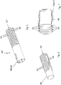
- eine perspektivische Ansicht eines Endabschnitts einer Hüllrohranordnung der Wickelwelle;
- Figur 4
- eine perspektivische Ansicht eines Endabschnitts eines Wellrohrs der Hüllrohranordnung nach
Figur 3 ; - Figur 5
- eine perspektivische Ansicht eines Endabschnitts einer alternativen Ausführungsform einer Hüllrohranordnung;
- Figur 6
- eine perspektivische Ansicht eines Endabschnitts eines Wellrohrs der Hüllrohranordnung nach
Figur 5 ; und - Figur 7
- einen Längsschnitt durch den Endabschnitt der Hüllrohranordnung nach
Figur 5 .
- figure 1
- a schematic plan view of a vehicle roof with a roller blind arrangement according to the invention;
- figure 2
- a schematic longitudinal section through a winding shaft of the blind assembly;
- figure 3
- a perspective view of an end portion of a cladding tube assembly of the winding shaft;
- figure 4
- a perspective view of an end portion of a corrugated tube according to the cladding tube arrangement
figure 3 ; - figure 5
- a perspective view of an end portion of an alternative embodiment of a cladding tube assembly;
- figure 6
- a perspective view of an end portion of a corrugated tube according to the cladding tube arrangement
figure 5 ; and - figure 7
- a longitudinal section through the end section of the cladding tube arrangement
figure 5 .
In
Das Fahrzeugdach 10 umfasst als Beschattungselement für den Dachausschnitt 12 eine Rolloanordnung 14, die eine Rollobahn 16 aus einem faltbaren bzw. wickelbaren, blickdichten Material aufweist. Die Rollobahn 16 ist an ihrem vorderen, sich in Dachquerrichtung erstreckenden Rand mit einem Zugspriegel 18 versehen, der ein Betätigungselement der Rolloanordnung 14 darstellt. An ihrem dem Zugspriegel 18 abgewandten Rand ist die Rollobahn 16 an eine Wickelwelle 20 angebunden, die sich ebenfalls in Dachquerrichtung erstreckt.The
Die in
Die Wickelwelle 20 umfasst des Weiteren eine flexible Hüllrohranordnung 30, welche von der Lagerstrebe 22 durchgriffen ist. Die Hüllrohranordnung 30 umfasst wiederum als flexibles Hüllrohrelement ein Wellrohr 32, das als Kunststoff-Vakuumformteil ausgebildet ist und das an seinen bezogen auf die vertikale Dachlängsmittelebene beidseits angeordneten Enden jeweils mit einer Koppelumspritzung 34A bzw. 34B aus Kunststoff versehen ist. Über die Koppelumspritzung 34A und 34B ist die Hüllrohranordnung 30 beidseits jeweils mit einer Lagerbuchse 36A bzw. 36B verbunden und so mit ihren Enden drehbar auf der Lagerstrebe 22 bzw. den Lagerzapfen 38A und 38B derselben gelagert.The winding
In den
In den
- 1010
- Fahrzeugdachvehicle roof
- 1212
- Dachöffnungroof opening
- 1414
- Rolloanordnungblind arrangement
- 1616
- Rollobahnroller blind
- 1818
- Zugspriegeldrawbar
- 2020
- Wickelwellewinding shaft
- 2222
- Lagerstrebebearing brace
- 24A, B24A, B
- Lagerelementbearing element
- 26A, B26A, B
- Führungsschieneguide rail
- 28A, B28A, B
- Führungsbandguide band
- 30,30'30,30'
- Hüllrohranordnungduct assembly
- 32,32'32,32'
- Wellrohrcorrugated pipe
- 34A, B34A, B
- Koppelumspritzungcoupling overmolding
- 36A, B36A, B
- Lagerbuchsebearing bush
- 38A, B38A, B
- Lagerzapfenbearing journal
- 4040
- Wellrohrrippecorrugated tube rib
- 4242
- Wellentaltrough
- 4444
- Aussparungrecess
- 4848
- Verbindungsstutzenconnector
Claims (6)
- A roller blind arrangement for a motor vehicle, the roller blind arrangement comprising a roller blind web (16) and a winding shaft (20) onto which the roller blind web (16) can be wound or from which the roller blind web (16) can be unwound and which comprises a flexible surrounding-tube arrangement (30, 30') penetrated by a vehicle-attached bearing strut (22) and comprising a corrugated tube (32, 32') as a surrounding-tube element, corrugated-tube ribs (40) being formed on the corrugated tube (32, 32') and being separated from each other by troughs (42), characterized in that the corrugated tube (32, 32') has a coupling overmold (34A, 34B) at each of its two ends, each coupling overmold (34A, 34B) being connected to a respective bearing bush (36A, 36B) and having an outer diameter which corresponds to the maximum outer diameter of the corrugated tube (32, 32').
- The roller blind arrangement according to claim 1, characterized in that the corrugated tube (32') has a cylindrical portion at each of its ends, each cylindrical portion being covered by the respective coupling overmold (34A, 34B).
- The roller blind arrangement according to claim 1 or 2, characterized in that the corrugated tube (32) has at least one recess (44) in each of its end portions, each recess (44) being filled by the respective coupling overmold (34A, 34B).
- The roller blind arrangement according to claim 3, characterized in that the recess (44) runs through at least one corrugated-tube rib (40), the recess (44) and at least one trough (42) of the corrugated tube (32) being filled by the coupling overmold (34A, 34B).
- The roller blind arrangement according to claim 3 or 4, characterized in that the recess (40) is a longitudinal slot or a longitudinal groove.
- The roller blind arrangement according to any one of claims 3 to 5, characterized in that the corrugated tube (32) has two recesses (44) in at least one of its two end portions, the recesses (44) being offset from each other by 180° in relation to the axis of the corrugated tube (32).
Applications Claiming Priority (2)
| Application Number | Priority Date | Filing Date | Title |
|---|---|---|---|
| DE102018123280.2A DE102018123280A1 (en) | 2018-09-21 | 2018-09-21 | Roller blind arrangement with corrugated tube winding shaft |
| PCT/EP2019/070188 WO2020057814A1 (en) | 2018-09-21 | 2019-07-26 | Roller blind arrangement having corrugated tube winding shaft |
Publications (2)
| Publication Number | Publication Date |
|---|---|
| EP3853052A1 EP3853052A1 (en) | 2021-07-28 |
| EP3853052B1 true EP3853052B1 (en) | 2022-10-12 |
Family
ID=67544194
Family Applications (1)
| Application Number | Title | Priority Date | Filing Date |
|---|---|---|---|
| EP19749643.3A Active EP3853052B1 (en) | 2018-09-21 | 2019-07-26 | Roller blind arrangement having corrugated tube winding shaft |
Country Status (5)
| Country | Link |
|---|---|
| US (1) | US11358442B2 (en) |
| EP (1) | EP3853052B1 (en) |
| CN (1) | CN112714704B (en) |
| DE (1) | DE102018123280A1 (en) |
| WO (1) | WO2020057814A1 (en) |
Families Citing this family (2)
| Publication number | Priority date | Publication date | Assignee | Title |
|---|---|---|---|---|
| DE102017119767A1 (en) * | 2017-08-29 | 2019-02-28 | Webasto SE | Roller blind arrangement with winding shaft cladding tube |
| CN113879082B (en) * | 2021-10-15 | 2022-07-19 | 福耀玻璃工业集团股份有限公司 | Reel, roll up curtain subassembly, printing opacity subassembly and vehicle |
Family Cites Families (14)
| Publication number | Priority date | Publication date | Assignee | Title |
|---|---|---|---|---|
| JP3749607B2 (en) * | 1997-11-27 | 2006-03-01 | カルソニックカンセイ株式会社 | Refrigerant piping and fastening method for vehicle air conditioner |
| NZ504541A (en) * | 1998-01-13 | 2000-12-22 | Formway Furniture Ltd | A table assembly with extensible modesty screen such that as top of table is adjusted vertically screen maintains privacy to user |
| DE102005032043C5 (en) | 2005-07-08 | 2015-04-16 | Webasto Ag | Roller blind device for a motor vehicle |
| US20080216970A1 (en) * | 2007-03-08 | 2008-09-11 | Macauto Industrial Co., Ltd. | Sunshade assembly suitable for an arcuate window |
| FR2945091B1 (en) * | 2009-04-30 | 2011-05-13 | Somfy Sas | DEVICE FOR VISCOELASTIC TRANSMISSION OF A ACTUATOR OF A SHUTTER |
| KR101107332B1 (en) * | 2010-02-03 | 2012-01-20 | 동아금속주름관(주) | Flexible pipe combined connecting apparatus for flexible pipe and combining method for using the same with flexible pipe |
| EP2529965B1 (en) * | 2011-06-01 | 2014-03-12 | Roof Systems Germany GmbH | Roller blind for a sliding roof system |
| JP6018784B2 (en) * | 2012-04-17 | 2016-11-02 | ベバスト ジャパン株式会社 | Roll shade device |
| DE102013102630B4 (en) | 2013-03-14 | 2023-02-02 | Webasto SE | Roller blind arrangement with winding shaft |
| US9598901B2 (en) * | 2013-09-18 | 2017-03-21 | Lutron Electronics Co., Inc. | Quiet motorized window treatment system |
| CN205078934U (en) * | 2015-11-10 | 2016-03-09 | 高明芳 | Interior ladder way electrothermal welding socket joint formula steel band bellows of heavy -calibre |
| CN108533851A (en) * | 2017-03-06 | 2018-09-14 | 新昌县四通机电有限公司 | Damping tube |
| JP2019018728A (en) * | 2017-07-18 | 2019-02-07 | アイシン精機株式会社 | Roll shade device |
| DE102017119767A1 (en) * | 2017-08-29 | 2019-02-28 | Webasto SE | Roller blind arrangement with winding shaft cladding tube |
-
2018
- 2018-09-21 DE DE102018123280.2A patent/DE102018123280A1/en active Pending
-
2019
- 2019-07-26 WO PCT/EP2019/070188 patent/WO2020057814A1/en unknown
- 2019-07-26 CN CN201980061470.XA patent/CN112714704B/en active Active
- 2019-07-26 US US17/270,708 patent/US11358442B2/en active Active
- 2019-07-26 EP EP19749643.3A patent/EP3853052B1/en active Active
Also Published As
| Publication number | Publication date |
|---|---|
| US20210331562A1 (en) | 2021-10-28 |
| CN112714704B (en) | 2022-10-28 |
| EP3853052A1 (en) | 2021-07-28 |
| CN112714704A (en) | 2021-04-27 |
| WO2020057814A1 (en) | 2020-03-26 |
| US11358442B2 (en) | 2022-06-14 |
| DE102018123280A1 (en) | 2020-03-26 |
Similar Documents
| Publication | Publication Date | Title |
|---|---|---|
| DE102005038373B4 (en) | Sun protection device | |
| EP1612070B1 (en) | Window roller blind for curved or non retangular window panes | |
| EP1904322B2 (en) | Blind assembly for a motor vehicle | |
| EP2181006B1 (en) | Blind arrangement for a motor vehicle | |
| EP3853052B1 (en) | Roller blind arrangement having corrugated tube winding shaft | |
| EP1626152A1 (en) | Solar protection device for glass roof | |
| DE10338900B4 (en) | Curved window blind for motor vehicles | |
| EP3676117B1 (en) | Rollerblind arrangement with winding casing | |
| EP3630514B1 (en) | Roller blind arrangement for a motor vehicle | |
| DE102004030262B3 (en) | Roller blind with conical winding shaft | |
| EP1986876B1 (en) | Shading device for a light-permeable window, in particular for motor vehicles | |
| DE102017110746A1 (en) | Roof roller blind system for a motor vehicle and method for mounting a roof roller blind system for a motor vehicle | |
| EP1669232A2 (en) | Blind apparatus with roller screen | |
| EP1369275A1 (en) | Roller blind with lateral guiding | |
| EP2979908A1 (en) | Shading device for a transparent surface of a motor vehicle | |
| DE102012102116B4 (en) | Assembly with a roller blind, and roof assembly | |
| DE102017129328A1 (en) | Sun blind system for a roof window of a motor vehicle, in particular for a sliding roof system | |
| EP1885571B1 (en) | Darkening device comprising a roller blind for a light-permeable window | |
| DE102013009083B4 (en) | Roof module for a vehicle roof | |
| EP2222491B1 (en) | Method for producing a sealing profile for a motor vehicle and such a sealing profile | |
| WO2007059755A1 (en) | Roller blind device, in particular, for a sliding roof system | |
| DE102012106974B4 (en) | Roof assembly and method for assembling a roof assembly for a convertible vehicle | |
| DE19925226A1 (en) | Black-out arrangement consists of flat flexible material contained in magazine with deflector with frictional surface | |
| DE102016111695A1 (en) | Rolloanordnung for a vehicle body and method for assembling the roller blind assembly | |
| DE202023106409U1 (en) | Winding device for a roller blind arrangement, roller blind arrangement and roof arrangement |
Legal Events
| Date | Code | Title | Description |
|---|---|---|---|
| STAA | Information on the status of an ep patent application or granted ep patent |
Free format text: STATUS: UNKNOWN |
|
| STAA | Information on the status of an ep patent application or granted ep patent |
Free format text: STATUS: THE INTERNATIONAL PUBLICATION HAS BEEN MADE |
|
| PUAI | Public reference made under article 153(3) epc to a published international application that has entered the european phase |
Free format text: ORIGINAL CODE: 0009012 |
|
| STAA | Information on the status of an ep patent application or granted ep patent |
Free format text: STATUS: REQUEST FOR EXAMINATION WAS MADE |
|
| 17P | Request for examination filed |
Effective date: 20210224 |
|
| AK | Designated contracting states |
Kind code of ref document: A1 Designated state(s): AL AT BE BG CH CY CZ DE DK EE ES FI FR GB GR HR HU IE IS IT LI LT LU LV MC MK MT NL NO PL PT RO RS SE SI SK SM TR |
|
| DAV | Request for validation of the european patent (deleted) | ||
| DAX | Request for extension of the european patent (deleted) | ||
| GRAP | Despatch of communication of intention to grant a patent |
Free format text: ORIGINAL CODE: EPIDOSNIGR1 |
|
| STAA | Information on the status of an ep patent application or granted ep patent |
Free format text: STATUS: GRANT OF PATENT IS INTENDED |
|
| INTG | Intention to grant announced |
Effective date: 20220509 |
|
| GRAS | Grant fee paid |
Free format text: ORIGINAL CODE: EPIDOSNIGR3 |
|
| GRAA | (expected) grant |
Free format text: ORIGINAL CODE: 0009210 |
|
| STAA | Information on the status of an ep patent application or granted ep patent |
Free format text: STATUS: THE PATENT HAS BEEN GRANTED |
|
| AK | Designated contracting states |
Kind code of ref document: B1 Designated state(s): AL AT BE BG CH CY CZ DE DK EE ES FI FR GB GR HR HU IE IS IT LI LT LU LV MC MK MT NL NO PL PT RO RS SE SI SK SM TR |
|
| REG | Reference to a national code |
Ref country code: GB Ref legal event code: FG4D Free format text: NOT ENGLISH |
|
| REG | Reference to a national code |
Ref country code: CH Ref legal event code: EP |
|
| REG | Reference to a national code |
Ref country code: DE Ref legal event code: R096 Ref document number: 502019005912 Country of ref document: DE |
|
| REG | Reference to a national code |
Ref country code: IE Ref legal event code: FG4D Free format text: LANGUAGE OF EP DOCUMENT: GERMAN |
|
| REG | Reference to a national code |
Ref country code: AT Ref legal event code: REF Ref document number: 1523951 Country of ref document: AT Kind code of ref document: T Effective date: 20221115 |
|
| REG | Reference to a national code |
Ref country code: LT Ref legal event code: MG9D |
|
| REG | Reference to a national code |
Ref country code: NL Ref legal event code: MP Effective date: 20221012 |
|
| PG25 | Lapsed in a contracting state [announced via postgrant information from national office to epo] |
Ref country code: NL Free format text: LAPSE BECAUSE OF FAILURE TO SUBMIT A TRANSLATION OF THE DESCRIPTION OR TO PAY THE FEE WITHIN THE PRESCRIBED TIME-LIMIT Effective date: 20221012 |
|
| PG25 | Lapsed in a contracting state [announced via postgrant information from national office to epo] |
Ref country code: SE Free format text: LAPSE BECAUSE OF FAILURE TO SUBMIT A TRANSLATION OF THE DESCRIPTION OR TO PAY THE FEE WITHIN THE PRESCRIBED TIME-LIMIT Effective date: 20221012 Ref country code: PT Free format text: LAPSE BECAUSE OF FAILURE TO SUBMIT A TRANSLATION OF THE DESCRIPTION OR TO PAY THE FEE WITHIN THE PRESCRIBED TIME-LIMIT Effective date: 20230213 Ref country code: NO Free format text: LAPSE BECAUSE OF FAILURE TO SUBMIT A TRANSLATION OF THE DESCRIPTION OR TO PAY THE FEE WITHIN THE PRESCRIBED TIME-LIMIT Effective date: 20230112 Ref country code: LT Free format text: LAPSE BECAUSE OF FAILURE TO SUBMIT A TRANSLATION OF THE DESCRIPTION OR TO PAY THE FEE WITHIN THE PRESCRIBED TIME-LIMIT Effective date: 20221012 Ref country code: FI Free format text: LAPSE BECAUSE OF FAILURE TO SUBMIT A TRANSLATION OF THE DESCRIPTION OR TO PAY THE FEE WITHIN THE PRESCRIBED TIME-LIMIT Effective date: 20221012 Ref country code: ES Free format text: LAPSE BECAUSE OF FAILURE TO SUBMIT A TRANSLATION OF THE DESCRIPTION OR TO PAY THE FEE WITHIN THE PRESCRIBED TIME-LIMIT Effective date: 20221012 |
|
| PG25 | Lapsed in a contracting state [announced via postgrant information from national office to epo] |
Ref country code: RS Free format text: LAPSE BECAUSE OF FAILURE TO SUBMIT A TRANSLATION OF THE DESCRIPTION OR TO PAY THE FEE WITHIN THE PRESCRIBED TIME-LIMIT Effective date: 20221012 Ref country code: PL Free format text: LAPSE BECAUSE OF FAILURE TO SUBMIT A TRANSLATION OF THE DESCRIPTION OR TO PAY THE FEE WITHIN THE PRESCRIBED TIME-LIMIT Effective date: 20221012 Ref country code: LV Free format text: LAPSE BECAUSE OF FAILURE TO SUBMIT A TRANSLATION OF THE DESCRIPTION OR TO PAY THE FEE WITHIN THE PRESCRIBED TIME-LIMIT Effective date: 20221012 Ref country code: IS Free format text: LAPSE BECAUSE OF FAILURE TO SUBMIT A TRANSLATION OF THE DESCRIPTION OR TO PAY THE FEE WITHIN THE PRESCRIBED TIME-LIMIT Effective date: 20230212 Ref country code: HR Free format text: LAPSE BECAUSE OF FAILURE TO SUBMIT A TRANSLATION OF THE DESCRIPTION OR TO PAY THE FEE WITHIN THE PRESCRIBED TIME-LIMIT Effective date: 20221012 Ref country code: GR Free format text: LAPSE BECAUSE OF FAILURE TO SUBMIT A TRANSLATION OF THE DESCRIPTION OR TO PAY THE FEE WITHIN THE PRESCRIBED TIME-LIMIT Effective date: 20230113 |
|
| REG | Reference to a national code |
Ref country code: DE Ref legal event code: R097 Ref document number: 502019005912 Country of ref document: DE |
|
| PG25 | Lapsed in a contracting state [announced via postgrant information from national office to epo] |
Ref country code: SM Free format text: LAPSE BECAUSE OF FAILURE TO SUBMIT A TRANSLATION OF THE DESCRIPTION OR TO PAY THE FEE WITHIN THE PRESCRIBED TIME-LIMIT Effective date: 20221012 Ref country code: RO Free format text: LAPSE BECAUSE OF FAILURE TO SUBMIT A TRANSLATION OF THE DESCRIPTION OR TO PAY THE FEE WITHIN THE PRESCRIBED TIME-LIMIT Effective date: 20221012 Ref country code: EE Free format text: LAPSE BECAUSE OF FAILURE TO SUBMIT A TRANSLATION OF THE DESCRIPTION OR TO PAY THE FEE WITHIN THE PRESCRIBED TIME-LIMIT Effective date: 20221012 Ref country code: DK Free format text: LAPSE BECAUSE OF FAILURE TO SUBMIT A TRANSLATION OF THE DESCRIPTION OR TO PAY THE FEE WITHIN THE PRESCRIBED TIME-LIMIT Effective date: 20221012 Ref country code: CZ Free format text: LAPSE BECAUSE OF FAILURE TO SUBMIT A TRANSLATION OF THE DESCRIPTION OR TO PAY THE FEE WITHIN THE PRESCRIBED TIME-LIMIT Effective date: 20221012 |
|
| PLBE | No opposition filed within time limit |
Free format text: ORIGINAL CODE: 0009261 |
|
| STAA | Information on the status of an ep patent application or granted ep patent |
Free format text: STATUS: NO OPPOSITION FILED WITHIN TIME LIMIT |
|
| PG25 | Lapsed in a contracting state [announced via postgrant information from national office to epo] |
Ref country code: SK Free format text: LAPSE BECAUSE OF FAILURE TO SUBMIT A TRANSLATION OF THE DESCRIPTION OR TO PAY THE FEE WITHIN THE PRESCRIBED TIME-LIMIT Effective date: 20221012 Ref country code: AL Free format text: LAPSE BECAUSE OF FAILURE TO SUBMIT A TRANSLATION OF THE DESCRIPTION OR TO PAY THE FEE WITHIN THE PRESCRIBED TIME-LIMIT Effective date: 20221012 |
|
| 26N | No opposition filed |
Effective date: 20230713 |
|
| PG25 | Lapsed in a contracting state [announced via postgrant information from national office to epo] |
Ref country code: SI Free format text: LAPSE BECAUSE OF FAILURE TO SUBMIT A TRANSLATION OF THE DESCRIPTION OR TO PAY THE FEE WITHIN THE PRESCRIBED TIME-LIMIT Effective date: 20221012 |
|
| PGFP | Annual fee paid to national office [announced via postgrant information from national office to epo] |
Ref country code: FR Payment date: 20230724 Year of fee payment: 5 Ref country code: DE Payment date: 20230720 Year of fee payment: 5 |
|
| PG25 | Lapsed in a contracting state [announced via postgrant information from national office to epo] |
Ref country code: MC Free format text: LAPSE BECAUSE OF FAILURE TO SUBMIT A TRANSLATION OF THE DESCRIPTION OR TO PAY THE FEE WITHIN THE PRESCRIBED TIME-LIMIT Effective date: 20221012 |
|
| PG25 | Lapsed in a contracting state [announced via postgrant information from national office to epo] |
Ref country code: MC Free format text: LAPSE BECAUSE OF FAILURE TO SUBMIT A TRANSLATION OF THE DESCRIPTION OR TO PAY THE FEE WITHIN THE PRESCRIBED TIME-LIMIT Effective date: 20221012 |
|
| REG | Reference to a national code |
Ref country code: CH Ref legal event code: PL |
|
| REG | Reference to a national code |
Ref country code: BE Ref legal event code: MM Effective date: 20230731 |
|
| PG25 | Lapsed in a contracting state [announced via postgrant information from national office to epo] |
Ref country code: LU Free format text: LAPSE BECAUSE OF NON-PAYMENT OF DUE FEES Effective date: 20230726 |
|
| GBPC | Gb: european patent ceased through non-payment of renewal fee |
Effective date: 20230726 |
|
| PG25 | Lapsed in a contracting state [announced via postgrant information from national office to epo] |
Ref country code: LU Free format text: LAPSE BECAUSE OF NON-PAYMENT OF DUE FEES Effective date: 20230726 |