EP3852965B1 - Verfahren zur schneidenden bearbeitung von rohren in einer laserrohrschneidmaschine sowie laserrohrschneidmaschine - Google Patents
Verfahren zur schneidenden bearbeitung von rohren in einer laserrohrschneidmaschine sowie laserrohrschneidmaschine Download PDFInfo
- Publication number
- EP3852965B1 EP3852965B1 EP19762372.1A EP19762372A EP3852965B1 EP 3852965 B1 EP3852965 B1 EP 3852965B1 EP 19762372 A EP19762372 A EP 19762372A EP 3852965 B1 EP3852965 B1 EP 3852965B1
- Authority
- EP
- European Patent Office
- Prior art keywords
- tube
- brace
- tool
- processing
- laser
- Prior art date
- Legal status (The legal status is an assumption and is not a legal conclusion. Google has not performed a legal analysis and makes no representation as to the accuracy of the status listed.)
- Active
Links
Images


Classifications
-
- B—PERFORMING OPERATIONS; TRANSPORTING
- B23—MACHINE TOOLS; METAL-WORKING NOT OTHERWISE PROVIDED FOR
- B23K—SOLDERING OR UNSOLDERING; WELDING; CLADDING OR PLATING BY SOLDERING OR WELDING; CUTTING BY APPLYING HEAT LOCALLY, e.g. FLAME CUTTING; WORKING BY LASER BEAM
- B23K26/00—Working by laser beam, e.g. welding, cutting or boring
- B23K26/0093—Working by laser beam, e.g. welding, cutting or boring combined with mechanical machining or metal-working covered by other subclasses than B23K
-
- B—PERFORMING OPERATIONS; TRANSPORTING
- B23—MACHINE TOOLS; METAL-WORKING NOT OTHERWISE PROVIDED FOR
- B23K—SOLDERING OR UNSOLDERING; WELDING; CLADDING OR PLATING BY SOLDERING OR WELDING; CUTTING BY APPLYING HEAT LOCALLY, e.g. FLAME CUTTING; WORKING BY LASER BEAM
- B23K26/00—Working by laser beam, e.g. welding, cutting or boring
- B23K26/08—Devices involving relative movement between laser beam and workpiece
- B23K26/0823—Devices involving rotation of the workpiece
-
- B—PERFORMING OPERATIONS; TRANSPORTING
- B23—MACHINE TOOLS; METAL-WORKING NOT OTHERWISE PROVIDED FOR
- B23K—SOLDERING OR UNSOLDERING; WELDING; CLADDING OR PLATING BY SOLDERING OR WELDING; CUTTING BY APPLYING HEAT LOCALLY, e.g. FLAME CUTTING; WORKING BY LASER BEAM
- B23K26/00—Working by laser beam, e.g. welding, cutting or boring
- B23K26/08—Devices involving relative movement between laser beam and workpiece
- B23K26/083—Devices involving movement of the workpiece in at least one axial direction
- B23K26/0853—Devices involving movement of the workpiece in at least two axial directions, e.g. in a plane
- B23K26/0861—Devices involving movement of the workpiece in at least two axial directions, e.g. in a plane in at least three axial directions
-
- B—PERFORMING OPERATIONS; TRANSPORTING
- B23—MACHINE TOOLS; METAL-WORKING NOT OTHERWISE PROVIDED FOR
- B23K—SOLDERING OR UNSOLDERING; WELDING; CLADDING OR PLATING BY SOLDERING OR WELDING; CUTTING BY APPLYING HEAT LOCALLY, e.g. FLAME CUTTING; WORKING BY LASER BEAM
- B23K37/00—Auxiliary devices or processes, not specially adapted for a procedure covered by only one of the other main groups of this subclass
- B23K37/04—Auxiliary devices or processes, not specially adapted for a procedure covered by only one of the other main groups of this subclass for holding or positioning work
- B23K37/0426—Fixtures for other work
- B23K37/0435—Clamps
-
- B—PERFORMING OPERATIONS; TRANSPORTING
- B23—MACHINE TOOLS; METAL-WORKING NOT OTHERWISE PROVIDED FOR
- B23P—METAL-WORKING NOT OTHERWISE PROVIDED FOR; COMBINED OPERATIONS; UNIVERSAL MACHINE TOOLS
- B23P23/00—Machines or arrangements of machines for performing specified combinations of different metal-working operations not covered by a single other subclass
- B23P23/02—Machine tools for performing different machining operations
-
- B—PERFORMING OPERATIONS; TRANSPORTING
- B23—MACHINE TOOLS; METAL-WORKING NOT OTHERWISE PROVIDED FOR
- B23Q—DETAILS, COMPONENTS, OR ACCESSORIES FOR MACHINE TOOLS, e.g. ARRANGEMENTS FOR COPYING OR CONTROLLING; MACHINE TOOLS IN GENERAL CHARACTERISED BY THE CONSTRUCTION OF PARTICULAR DETAILS OR COMPONENTS; COMBINATIONS OR ASSOCIATIONS OF METAL-WORKING MACHINES, NOT DIRECTED TO A PARTICULAR RESULT
- B23Q1/00—Members which are comprised in the general build-up of a form of machine, particularly relatively large fixed members
- B23Q1/72—Auxiliary arrangements; Interconnections between auxiliary tables and movable machine elements
- B23Q1/76—Steadies; Rests
- B23Q1/766—Steadies or rests moving together with the tool support
Definitions
- the invention relates to a method for the cutting processing of tubes in a laser tube cutting machine and a laser tube cutting machine, in particular for carrying out the method.
- This laser tube cutting machine includes a workpiece moving device, by which a tube to be machined is held and moved relative to a push-through device supporting the tube.
- a laser processing device is provided adjacent to the push-through device in a processing room. This includes a processing head through which a laser beam is directed onto the pipe.
- a tool holder is additionally provided in the processing space adjacent to the laser processing device in order to accommodate a tool for the mechanical processing of the tube.
- This tool is moved in an axis of movement perpendicular to the longitudinal axis of the tube, along which it can be moved relative to the push-through device, towards the tube for mechanical processing. While the tube is being processed, it is held by the clamping jaws of the push-through device. These clamping jaws exhibit flexibility when a preset clamping force is exceeded, which is not exceeded during laser processing, since no forces occur that have to be absorbed by the push-through device. Higher forces can occur during mechanical processing, which exceed the preset clamping force of the clamping jaws. Because of the resilience of at least one clamping jaw, this can result in a positional offset of the pipe within the push-through device come and impair the mechanical processing or make it impossible.
- This processing device comprises a catching lance with a collecting opening, which is inserted into the pipe to be processed during processing of the pipe and the collecting opening of the catching lance is positioned below the processing point.
- a workpiece support is provided, which is positioned in a processing machine for cutting pipes between a workpiece moving device for receiving and shifting the pipe and a push-through device.
- An analog device goes out of the CN 203621737 U out.
- a device for clamping workpieces which is provided for a workpiece moving device, which receives a pipe to be machined and through which the pipe to be machined can be moved relative to a push-through device.
- JP 62-173 129A discloses a machine for machining tubes.
- This clamping device has a chuck through which the pipe is firmly clamped. Any lateral force that occurs due to mechanical processing is absorbed by the clamping force of the chuck.
- a vibration damping device is additionally brought into contact with an inside of the pipe in order to increase the processing quality.
- the invention is based on the object of proposing a method for processing pipes in a laser pipe cutting machine and a laser pipe cutting machine, as a result of which additional mechanical processing of the pipe with a tool is possible in addition to laser processing.
- a method for the cutting processing of pipes in a laser pipe cutting machine in which the pipe is mechanically processed with a tool in addition to the laser processing and at least one counterholder is moved with the tool into a working position for contact with the pipe before the start of the mechanical processing of the pipe becomes.
- This counterholder which can be moved into the working position, can be used to support the pipe, which counteracts the introduction of force through the tool during mechanical processing.
- the counter-holder can absorb forces which cannot be absorbed by the clamping jaws of the push-through device.
- both a machining or cutting machining of the tube by means of the laser beam and a mechanical machining of the tube with the at least one tool can take place in succession. Machining such as machining, flow drilling, furrowing, broaching, grinding, brushing, thread cutting or the like can preferably be carried out.
- the at least one counterholder is held stationary in the working position. Irrespective of the force applied by the tool to the tube, the counterholder absorbs the forces during mechanical processing without yielding.
- a further preferred embodiment of the method provides that the counter-holder is transferred to the working position for resting on an outside of the pipe. This allows for easy external feeding into the working position and when not in use into a remote resting position.
- the tool for machining the tube is fed from the outside against the tube.
- the counterholder and the machining forces exerted by the tool act on the pipe from an outside during the mechanical machining.
- a further preferred embodiment of the method provides that the Counter-holder during laser processing of the tube in a rest position is positioned away from the tube and is transferred to the tool in the working position for the system before the mechanical processing of the tube. This prevents any contamination of the counter-holder from burn-off, slag or the like during the laser cutting.
- a counter-holder counteracting at least the uniaxial introduction of force is preferably moved into the working position.
- the tube can be machined without any misalignment.
- the counter holder can absorb the reaction force of the tube directly.
- the counter-holder and the tool are preferably moved in the same movement axis for simple control and introduction of force from the tool to the pipe and for the counter-holder to absorb the reaction force.
- this axis of movement is perpendicular to the longitudinal axis of the tube.
- a counter-holder with a gripping device additionally provided on the counter-holder is preferably moved into the working position relative to the pipe.
- the counter-holder preferably counteracts a first direction in which the force is introduced through the tool.
- the gripping device preferably counteracts a second direction of force application perpendicular to the first force application direction of the tool, so that the tube is secured by the counterholder and the gripping device against deflection in two axes - i.e. contrary to the first and second force application direction.
- the first force application direction and the second force application direction are preferably aligned perpendicular to the longitudinal axis of the tube.
- a further preferred embodiment of the method provides that the counter-holder and/or the gripping device each comprise at least one pressure piece. As a result, a secure system and absorption of the reaction force can be achieved during mechanical processing by the tool.
- the gripping device has two pressure pieces located opposite one another, which are moved towards one another in opposite directions into the working position for contact with the outside of the pipe.
- a clamping function can be exerted on the pipe in order to secure the initial position of the pipe, defined by the push-through device, for the subsequent mechanical processing.
- the pressure piece preferably has a punctiform, planar or linear support.
- rolling pressure pieces can be transferred to rest on the pipe. These rolling pressure pieces, which can be formed by rollers, balls, rollers or the like, are used in particular for mechanical processing of the pipe, in which a movement of the pipe along its longitudinal axis is also superimposed.
- a laser tube cutting machine for the cutting processing of tubes, which comprises a workpiece support device, which receives the tube and moves relative to a push-through device supporting the tube, which guides the tube by means of clamping jaws of the push-through device and with a laser processing device, which has a processing head that directs a laser beam emerging from the processing head onto the pipe and with at least one additional tool for mechanical processing of the pipe, which can be moved in at least one direction of movement relative to the pipe, with at least one counter-holder being able to be moved into a working position for contact with the pipe is, which acts in the opposite direction to the force introduction direction of the tool.
- Preferred embodiments of the laser tube cutting machine are given in dependent claims 10-15.
- the counter-holder preferably has a drive which moves the counter-holder into the working position and a rest position.
- the counterholder can be positioned as required to rest and support the pipe. Particularly in the case of laser cutting, the counter-holder is moved to a rest position away from the tube.
- the drive can include a pneumatic or hydraulic cylinder, an electric linear drive or the like for controlling the movement.
- the drive can also have an integrated lateral guide.
- the drive can be clamped or secured in an extended position. The counter-holder thus forms a fixed, non-yielding abutment.
- the counter-holder preferably has at least one pressure piece, which has a punctiform, linear, planar or rolling support.
- the design of the pressure pieces can also depend on the geometry of the pipes.
- the pressure piece is preferably made of an elastic material. This enables the counterholder to be positioned on the pipe to be processed without scratching.
- the counter-holder can additionally have a gripping device which, unlike the counter-holder, which absorbs a first reaction force, counteracts a second reaction force.
- a gripping device which, unlike the counter-holder, which absorbs a first reaction force, counteracts a second reaction force.
- the gripping device for absorbing the second reaction force of the tube preferably acts perpendicularly to the counter-holder, which absorbs the first reaction force.
- two opposing pressure pieces are preferably provided, which have a the clamping force acting on the pipe can be positioned relative to the pipe.
- a simple adaptation to different cross sections of the pipe to be processed can be achieved.
- a sufficient clamping force can be applied via the gripping device without the pipe being deformed as a result.
- the pressure pieces of the gripping device can preferably be moved with a drive.
- This drive can be sensor-controlled so that a clamping force matched by the tube can be set.
- a laser tube cutting machine 1 is shown schematically simplified.
- This laser tube cutting machine 1 is provided for the cutting processing of workpieces 2, the workpieces 2 being rod-shaped, in particular tubular. However, in particular, profiles are also to be understood as rod-shaped.
- This laser tube cutting machine 1 includes a feed device 3 for laterally feeding the tube 2 to be cut to the laser tube cutting machine 1 , for example by a loading device 19 .
- the tube is processed by a laser processing device 24 for laser cutting of the tube 2, in particular of rod sections or tube parts and/or by a processing device 4, for mechanical processing with a tool 33.
- the finished tubes 2 , bar sections or tube parts are picked up by an unloading device 5 and removed from the laser tube cutting machine 1 . All essential functions of the laser tube cutting machine 1 are controlled with a numerical control device 6 .
- the feeding device 3 comprises a rotating and feeding device serving as a workpiece moving device 7, as well as a machine bed 8 with guide rails 9 and a push-through device 10.
- the workpiece moving device 7 is motor-driven and can be moved on the guide rails 9 in the feed direction 11.
- the tube 2 to be fed is fixed with a clamping device 12 of the workpiece moving device 7, which can be rotated in the direction of the double arrow 13 and encloses the tube 2 fed from the outside and clamps it in place.
- the pipe 2 is supported by at least one workpiece support 14 integrated into the machine bed 8 during the feed to the push-through device 10 and/or during the processing of the pipe 2 .
- the workpiece 2 is guided through the push-through device 10 and supported by it.
- the push-through device 10 is designed in such a way that the clamped pipe 2 is guided in the feed direction and is not clamped in place.
- the tube 2 can be rotated about the axis of rotation 13 in the push-through device 10 .
- the laser processing device 24 comprises a laser beam source 15 for generating a laser beam 16 , a processing head 17 and a beam guide 18 which guides the laser beam 16 from the laser beam source 15 to the processing head 17 .
- the laser beam 16 exits the processing head 17 and is projected onto the outer peripheral surface of the pipe 2 at a processing point F within the processing space 20 focused.
- a tool holder 21 of the machining device 4 is provided associated with the machining space 20 and/or adjacent to the machining head 17 and which can be guided by a guide 22 ( figure 2 ) can be moved at least within the processing space 20, so that the tool holder 21 with a tool 33 clamped therein can be moved to the processing point F and in turn can be removed from it.
- a magazine 25 can be provided at a distance from the processing point F.
- This magazine 25 can be designed, for example, as a linear magazine or revolver magazine.
- Various tools 33 such as drills, flow drills, thread-cutting tools or thread-forming tools, can be stored in this magazine 25.
- the tool holder 21 can preferably be moved in the Y direction at least between the magazine 25 and the machining point F according to the double arrow 26 shown.
- the tool holder 21 can also be movable in the Z direction.
- the magazine 25 can also be moved in the Z direction.
- the unloading device 5 On the side of the push-through device 10 facing away from the machine bed 8 , the unloading device 5 is provided, which removes workpiece parts or sections cut from the tube 2 and a residual workpiece from the laser tube cutting machine 1 .
- FIG 2 a schematic side view of the push-through device 10 is shown.
- the push-through device 10 comprises a plurality of clamping jaws 34 which are flexibly accommodated in the push-through device 10 .
- clamping jaws 34 are provided, which are arranged in pairs opposite one another and offset by 90° from one another.
- the clamping jaws 34 can be adjustable with regard to their clamping force.
- These clamping jaws 34 which preferably have rollers 35 that rest against the tube 2, can be used to guide the tube 2 for the laser cutting process.
- a counter-holder 41 is provided in the processing space 20 .
- This counter-holder 41 includes a drive 42, through which a pressure piece 43 of the counter-holder 41 in an in figure 2 shown working position 46 can be transferred. In this working position 46 the pressure piece 43 rests against an outside of the pipe 2 .
- the pressure piece 43 is positioned away from the tube 2 in a rest position that is not shown in detail.
- the pressure piece 43 is preferably positioned in the working position 46 and the rest position remote therefrom by a displacement movement along a Y-axis. This displacement movement is controlled by the drive 42 .
- the drive 42 can be effected by a pneumatic, hydraulic cylinder. An electric linear drive or the like can also be provided.
- the counter-holder 41 is actuated by the control device 6.
- the pressure piece 43 can be in the form of a surface or a plate.
- a contact surface 47 of the pressure piece 43 can preferably be made of an elastic material, in particular plastic, in order to avoid pressure points or scratches.
- the pressure piece 43 can also have a circular or V-shaped edge that is curved in the direction of the pipe 2 .
- Tool 33 is in figure 2 shown in a position just before it engages the pipe 2 for processing.
- the tool 33 is moved towards the outside of the pipe 2 along the X-axis.
- the counter-holder 41 counteracts this uniaxial introduction of force with a first reaction force.
- the counter-holder 41 can be positioned in a fixed position in the working position 46 .
- the cylinder can have an integrated clamping or locking function for this purpose.
- FIG 3 is a schematic view of the push-through device 10 with the tool 33 and the counter-holder 41 positioned relative to the tube 2.
- the counter-holder 41 acts on the outside of the pipe 2 .
- the tool 33 is also fed to the outside of the tube 2 opposite.
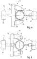
- FIG 4 A schematic side view of an alternative embodiment of the counterholder 41 is shown.
- This counter-holder 41 has a gripping device 51 in addition to a pressure piece 43 which counteracts a first force application direction.
- This gripping device 51 forms a second reaction force, which counteracts a further direction in which the force is introduced, for example in the Z direction.
- a second direction of introduction of force which is perpendicular to the first force device, can also be counteracted.
- the gripping device 51 has, for example, two pressure pieces 43 lying opposite one another. These pressure pieces 43 lying opposite one another can be moved towards one another with an actuator 52 in order to act on the outside of the pipe 2 . As a result, a three-point support on the tube 2 is given with the pressure piece 43 as a counter-holder 41 .
- the tube 2 can thus be held in a defined position in the Y-direction and in the Z-direction when a force is introduced by the tool 33 .
- a force introduced by the tool 33 in the X-direction is absorbed by the workpiece moving device 7 since the tube 2 is pressure and tension stable.
- a clamping function can be controlled by the actuating drive 52 of the gripping device 51 .
- This clamping function acting on the tube 2 can be greater than the preset clamping force of the clamping jaws 34 .
- the adjustable clamping force is adapted to the inherent rigidity of the tube 2 in order to prevent the tube 2 from being deformed.
- the pressure pieces 43 of the gripping device 51 can be designed analogously to the pressure piece 43 of the counter-holder 41 .
- FIG 5 is an alternative embodiment of the counter-holder 41 with the gripping device 51 figure 4 shown.
- This embodiment differs in the design of the pressure pieces 43.
- the pressure pieces 43 are in accordance with the embodiment figure 5 formed by rotatably mounted balls or rollers. This has the advantage that, during mechanical processing by the tool 33, the tube 2 can also be moved by the workpiece moving device 7 along the longitudinal axis of the tube 2, in particular in the X direction. As a result, a friction-minimised guidance can be achieved.
- non-rolling pressure pieces can also be provided, which have a material with high sliding properties for support.
Landscapes
- Engineering & Computer Science (AREA)
- Physics & Mathematics (AREA)
- Optics & Photonics (AREA)
- Mechanical Engineering (AREA)
- Plasma & Fusion (AREA)
- Laser Beam Processing (AREA)
- Drilling And Boring (AREA)
- Machine Tool Units (AREA)
Applications Claiming Priority (2)
| Application Number | Priority Date | Filing Date | Title |
|---|---|---|---|
| DE102018122717.5A DE102018122717A1 (de) | 2018-09-17 | 2018-09-17 | Verfahren zur schneidenden Bearbeitung von Rohren in einer Laserrohrschneidmaschine sowie Laserrohrschneidmaschine |
| PCT/EP2019/073323 WO2020057951A1 (de) | 2018-09-17 | 2019-09-02 | Verfahren zur schneidenden bearbeitung von rohren in einer laserrohrschneidmaschine sowie laserrohrschneidmaschine |
Publications (2)
| Publication Number | Publication Date |
|---|---|
| EP3852965A1 EP3852965A1 (de) | 2021-07-28 |
| EP3852965B1 true EP3852965B1 (de) | 2022-11-02 |
Family
ID=67841073
Family Applications (1)
| Application Number | Title | Priority Date | Filing Date |
|---|---|---|---|
| EP19762372.1A Active EP3852965B1 (de) | 2018-09-17 | 2019-09-02 | Verfahren zur schneidenden bearbeitung von rohren in einer laserrohrschneidmaschine sowie laserrohrschneidmaschine |
Country Status (6)
| Country | Link |
|---|---|
| US (1) | US12151304B2 (https=) |
| EP (1) | EP3852965B1 (https=) |
| JP (1) | JP2022500248A (https=) |
| CN (1) | CN113195147B (https=) |
| DE (1) | DE102018122717A1 (https=) |
| WO (1) | WO2020057951A1 (https=) |
Families Citing this family (10)
| Publication number | Priority date | Publication date | Assignee | Title |
|---|---|---|---|---|
| IT202100003977A1 (it) * | 2021-02-22 | 2022-08-22 | Adige Spa | Macchina per la lavorazione laser di tubi e profili con sistema automatico per l’applicazione di inserti filettati integrato nella macchina |
| JP2023061656A (ja) * | 2021-10-20 | 2023-05-02 | 住友重機械工業株式会社 | 加工対象物支持装置及びレーザ加工装置 |
| IT202200005192A1 (it) | 2022-03-16 | 2023-09-16 | Texa Dynamics S R L | “Motore elettrico con componente raffreddante” |
| CN114799916B (zh) * | 2022-05-17 | 2023-04-07 | 深圳市启航顺精密五金有限公司 | 一种锔钉加工用分段切断设备 |
| CN115570280A (zh) * | 2022-10-24 | 2023-01-06 | 新代科技(苏州)有限公司 | 一种激光同动切割管材的装置及其使用方法 |
| CN115847109B (zh) * | 2022-12-19 | 2025-07-08 | 广州江河幕墙系统工程有限公司 | 一种铝合金龙骨自动加工生产线及加工方法 |
| CN116984822A (zh) * | 2023-09-13 | 2023-11-03 | 长沙立诚机械有限公司 | 一种复杂结构件铆焊工装平台 |
| CN119794593A (zh) * | 2024-06-12 | 2025-04-11 | 广东隆信激光智能装备有限公司 | 一种稳定夹持的激光切割设备 |
| CN118664126B (zh) * | 2024-08-23 | 2024-12-13 | 山东布莱特威健身器材有限公司 | 一种健身器材配件加工用激光切割设备 |
| CN119748125A (zh) * | 2025-01-20 | 2025-04-04 | 江苏哲雪冷链设备有限公司 | 一种空调压缩机主壳体冲孔整形一体化生产设备 |
Family Cites Families (19)
| Publication number | Priority date | Publication date | Assignee | Title |
|---|---|---|---|---|
| JPS4821111Y1 (https=) | 1968-12-05 | 1973-06-19 | ||
| JPS62173129A (ja) * | 1986-01-28 | 1987-07-30 | Kawasaki Steel Corp | 管切削時のびびり防止装置 |
| DE102004020945B3 (de) | 2004-04-28 | 2006-01-19 | Kuka Schweissanlagen Gmbh | Verfahren und Einrichtung zum Fertigen von Ersatzteilen von Greifeinrichtungen |
| ATE458571T1 (de) * | 2007-07-17 | 2010-03-15 | Trumpf Werkzeugmaschinen Gmbh | Maschinelle anordnung zum bearbeiten von stabartigen werkstücken mit einer einrichtung zur werkstückabstützung |
| DE102008016734A1 (de) * | 2008-03-31 | 2009-10-08 | Trumpf Werkzeugmaschinen Gmbh + Co. Kg | Verfahren zur Optimierung der Belegung eines Rohrs oder mehrerer Rohre mit mehreren zu schneidenden Rohrteilen für eine Bearbeitungsanlage |
| US8735774B2 (en) | 2009-03-27 | 2014-05-27 | Electro Scientific Industries, Inc. | Force reaction compensation system |
| EP2548691B1 (de) * | 2011-07-22 | 2016-08-31 | TRUMPF Werkzeugmaschinen GmbH + Co. KG | Entladevorrichtung für eine Bearbeitungsvorrichtung zur Bearbeitung von Rohren mit einer in Höhenrichtung beweglichen Ablagefläche ; Verfahren zur schneidenden Bearbeitung eines Rohres mit einer solchen Vorrichtung |
| DE102012109434A1 (de) | 2012-10-04 | 2014-04-24 | Groz-Beckert Kg | Verfahren und Werkzeugeinheit zur Einstellung eines Stanzspalts |
| DE102013214019B3 (de) * | 2013-07-17 | 2014-09-11 | Trumpf Werkzeugmaschinen Gmbh + Co. Kg | Spannvorrichtung zum Positionieren von Werkstücken, Werkzeugmaschine mit einer derartigen Spannvorrichtung, Verfahren zum Positionieren von Werkstücken mittels einer derartigen Spannvorrichtung |
| CN203621737U (zh) * | 2013-12-06 | 2014-06-04 | 武汉华俄激光工程有限公司 | 一种简易自定心激光切管辅助支撑装置 |
| JP6193803B2 (ja) | 2014-05-19 | 2017-09-06 | 株式会社松浦機械製作所 | 振れ止め装置 |
| US20170368586A1 (en) | 2015-03-19 | 2017-12-28 | Westfalia Metallschlauchtechnik Gmbh & Co. Kg | Apparatus and method for producing strip wound tubes |
| DE102015115456A1 (de) | 2015-09-14 | 2017-03-16 | Westfalia Metallschlauchtechnik Gmbh & Co. Kg | Verarbeitungsverfahren und -vorrichtung für Leitungselemente |
| JP2017045877A (ja) * | 2015-08-27 | 2017-03-02 | ファナック株式会社 | 部品の脱落検出が可能なプリント基板および脱落検出回路 |
| DE102016104107B4 (de) * | 2016-03-07 | 2024-08-08 | TRUMPF Werkzeugmaschinen SE + Co. KG | Einrichtung zur Abstützung von Werkstücken, eine Werkstückabstützung sowie eine maschinelle Anordnung zur Bearbeitung von Werkstücken |
| DE102016106067A1 (de) * | 2016-04-04 | 2017-10-05 | Trumpf Werkzeugmaschinen Gmbh + Co. Kg | Verfahren und Bearbeitungsmaschine zum schneidenden Bearbeiten von plattenförmigen oder stabförmigen Werkstücken |
| DE102016221227A1 (de) | 2016-10-27 | 2018-05-03 | Trumpf Werkzeugmaschinen Gmbh + Co. Kg | Vorrichtung zum Einspannen von Werkstücken sowie Anordnung und Werkzeugmaschine mit einer derartigen Vorrichtung |
| JP6845502B2 (ja) | 2017-02-22 | 2021-03-17 | 日本車輌製造株式会社 | レーザ加工機および芯出し方法 |
| CN207239432U (zh) * | 2017-07-11 | 2018-04-17 | 东莞市力星激光科技有限公司 | 一种新型整体式紧凑型激光切管机 |
-
2018
- 2018-09-17 DE DE102018122717.5A patent/DE102018122717A1/de not_active Withdrawn
-
2019
- 2019-09-02 US US17/268,629 patent/US12151304B2/en active Active
- 2019-09-02 JP JP2021510324A patent/JP2022500248A/ja active Pending
- 2019-09-02 WO PCT/EP2019/073323 patent/WO2020057951A1/de not_active Ceased
- 2019-09-02 EP EP19762372.1A patent/EP3852965B1/de active Active
- 2019-09-02 CN CN201980060731.6A patent/CN113195147B/zh active Active
Also Published As
| Publication number | Publication date |
|---|---|
| CN113195147A (zh) | 2021-07-30 |
| DE102018122717A1 (de) | 2020-03-19 |
| EP3852965A1 (de) | 2021-07-28 |
| JP2022500248A (ja) | 2022-01-04 |
| US12151304B2 (en) | 2024-11-26 |
| CN113195147B (zh) | 2023-03-10 |
| US20210354233A1 (en) | 2021-11-18 |
| WO2020057951A1 (de) | 2020-03-26 |
Similar Documents
| Publication | Publication Date | Title |
|---|---|---|
| EP3852965B1 (de) | Verfahren zur schneidenden bearbeitung von rohren in einer laserrohrschneidmaschine sowie laserrohrschneidmaschine | |
| EP2611555B1 (de) | Biegerichtmaschine für ein langes werkstück und zu- und abfördervorrichtung hierfür sowie verfahren zum biegerichten von langen werkstücken | |
| EP3439822B1 (de) | Verfahren zum schneidenden bearbeiten von plattenförmigen oder stabförmigen werkstücken | |
| EP1260307B1 (de) | Werkzeugmaschine und Verfahren zur Bearbeitung eines stangenförmigen Werkstücks | |
| EP0958884A1 (de) | Verfahren zum Bearbeiten von Werkstücken sowie Werkzeugmaschine | |
| EP3356098A1 (de) | Bearbeitungsvorrichtung | |
| DE102016104107B4 (de) | Einrichtung zur Abstützung von Werkstücken, eine Werkstückabstützung sowie eine maschinelle Anordnung zur Bearbeitung von Werkstücken | |
| EP3664945B1 (de) | Biegemaschine zum biegen von stab- oder rohrförmigen werkstücken | |
| EP2279819A2 (de) | Vorrichtung zum mechanischen Bearbeiten von rohr- oder stangenförmigen Werkstücken | |
| EP1459816A1 (de) | Biegeeinrichtung mit Mehrniveaubiegewerkzeug sowie Spannbacken-und Gleitschienenstützeinheit für eine derartige Biegeeinrichtung | |
| EP1884303B1 (de) | Verfahren zum Zentrieren von Werkstücken sowie Vorrichtung zur Durchführung eines solchen Verfahrens | |
| EP1210995B1 (de) | Maschine für die Bearbeitung von Werkstücken, insbesondere von Blechen, mit wenigstens einer Biegestation sowie wenigstens einer Fügevorrichtung | |
| WO2022128535A1 (de) | Nachsetzeinrichtung und verfahren zum nachsetzen für ein plattenförmiges werkstück in einer bearbeitungsmaschine | |
| EP3302840B1 (de) | Fertigungsanlage zur fertigung von werkstücken aus blech sowie verfahren dazu | |
| DE102017121295A1 (de) | Mehrspindeldrehmaschine | |
| EP2475474B1 (de) | Biegemaschine zum biegen von länglichen werkstücken, insbesondere von rohren bzw. profilen | |
| WO2010139440A1 (de) | Werkzeugmaschine | |
| DE102020002320A1 (de) | Vorrichtung zum Übergeben von Werkzeugen, Werkzeugaggregaten und dergleichen, insbesondere zur Bearbeitung von Werkstücken aus Holz, Kunststoff, Aluminium und dergleichen, Anlage mit einer solchen Vorrichtung und Verfahren zum Übergeben von Werkzeugen, Werkzeugaggregaten und dergleichen | |
| DE10331985A1 (de) | Vorrichtung zur Innenbearbeitung von rohrförmigen Werkstücken und Zwangsführungseinrichtung | |
| DE10145674B4 (de) | Werkzeugmaschine zur Bearbeitung eines stangenförmigen Werkstücks | |
| DE102015205350A1 (de) | Vorrichtung und Verfahren zur spanenden Bearbeitung eines Werkstücks | |
| WO2020187693A2 (de) | Vorrichtung zum einbringen eines trennmittels in ein hohlförmiges werkstück | |
| EP0962279A2 (de) | Werkzeugmaschine und Verfahren zur Bearbeitung eines Werkstücks | |
| EP1453631B1 (de) | Tiefbohreinrichtung | |
| WO2026087321A1 (de) | Werkzeugwechsel-vorrichtung, kehlmaschine mit einer werkzeugwechsel-vorrichtung |
Legal Events
| Date | Code | Title | Description |
|---|---|---|---|
| STAA | Information on the status of an ep patent application or granted ep patent |
Free format text: STATUS: UNKNOWN |
|
| STAA | Information on the status of an ep patent application or granted ep patent |
Free format text: STATUS: THE INTERNATIONAL PUBLICATION HAS BEEN MADE |
|
| PUAI | Public reference made under article 153(3) epc to a published international application that has entered the european phase |
Free format text: ORIGINAL CODE: 0009012 |
|
| STAA | Information on the status of an ep patent application or granted ep patent |
Free format text: STATUS: REQUEST FOR EXAMINATION WAS MADE |
|
| 17P | Request for examination filed |
Effective date: 20210419 |
|
| AK | Designated contracting states |
Kind code of ref document: A1 Designated state(s): AL AT BE BG CH CY CZ DE DK EE ES FI FR GB GR HR HU IE IS IT LI LT LU LV MC MK MT NL NO PL PT RO RS SE SI SK SM TR |
|
| DAV | Request for validation of the european patent (deleted) | ||
| DAX | Request for extension of the european patent (deleted) | ||
| GRAP | Despatch of communication of intention to grant a patent |
Free format text: ORIGINAL CODE: EPIDOSNIGR1 |
|
| STAA | Information on the status of an ep patent application or granted ep patent |
Free format text: STATUS: GRANT OF PATENT IS INTENDED |
|
| INTG | Intention to grant announced |
Effective date: 20220428 |
|
| GRAS | Grant fee paid |
Free format text: ORIGINAL CODE: EPIDOSNIGR3 |
|
| GRAA | (expected) grant |
Free format text: ORIGINAL CODE: 0009210 |
|
| STAA | Information on the status of an ep patent application or granted ep patent |
Free format text: STATUS: THE PATENT HAS BEEN GRANTED |
|
| AK | Designated contracting states |
Kind code of ref document: B1 Designated state(s): AL AT BE BG CH CY CZ DE DK EE ES FI FR GB GR HR HU IE IS IT LI LT LU LV MC MK MT NL NO PL PT RO RS SE SI SK SM TR |
|
| REG | Reference to a national code |
Ref country code: GB Ref legal event code: FG4D Free format text: NOT ENGLISH |
|
| REG | Reference to a national code |
Ref country code: CH Ref legal event code: EP Ref country code: AT Ref legal event code: REF Ref document number: 1528405 Country of ref document: AT Kind code of ref document: T Effective date: 20221115 |
|
| REG | Reference to a national code |
Ref country code: DE Ref legal event code: R096 Ref document number: 502019006146 Country of ref document: DE |
|
| REG | Reference to a national code |
Ref country code: IE Ref legal event code: FG4D Free format text: LANGUAGE OF EP DOCUMENT: GERMAN |
|
| REG | Reference to a national code |
Ref country code: LT Ref legal event code: MG9D |
|
| REG | Reference to a national code |
Ref country code: NL Ref legal event code: MP Effective date: 20221102 |
|
| PG25 | Lapsed in a contracting state [announced via postgrant information from national office to epo] |
Ref country code: SE Free format text: LAPSE BECAUSE OF FAILURE TO SUBMIT A TRANSLATION OF THE DESCRIPTION OR TO PAY THE FEE WITHIN THE PRESCRIBED TIME-LIMIT Effective date: 20221102 Ref country code: PT Free format text: LAPSE BECAUSE OF FAILURE TO SUBMIT A TRANSLATION OF THE DESCRIPTION OR TO PAY THE FEE WITHIN THE PRESCRIBED TIME-LIMIT Effective date: 20230302 Ref country code: NO Free format text: LAPSE BECAUSE OF FAILURE TO SUBMIT A TRANSLATION OF THE DESCRIPTION OR TO PAY THE FEE WITHIN THE PRESCRIBED TIME-LIMIT Effective date: 20230202 Ref country code: LT Free format text: LAPSE BECAUSE OF FAILURE TO SUBMIT A TRANSLATION OF THE DESCRIPTION OR TO PAY THE FEE WITHIN THE PRESCRIBED TIME-LIMIT Effective date: 20221102 Ref country code: FI Free format text: LAPSE BECAUSE OF FAILURE TO SUBMIT A TRANSLATION OF THE DESCRIPTION OR TO PAY THE FEE WITHIN THE PRESCRIBED TIME-LIMIT Effective date: 20221102 Ref country code: ES Free format text: LAPSE BECAUSE OF FAILURE TO SUBMIT A TRANSLATION OF THE DESCRIPTION OR TO PAY THE FEE WITHIN THE PRESCRIBED TIME-LIMIT Effective date: 20221102 |
|
| PG25 | Lapsed in a contracting state [announced via postgrant information from national office to epo] |
Ref country code: RS Free format text: LAPSE BECAUSE OF FAILURE TO SUBMIT A TRANSLATION OF THE DESCRIPTION OR TO PAY THE FEE WITHIN THE PRESCRIBED TIME-LIMIT Effective date: 20221102 Ref country code: PL Free format text: LAPSE BECAUSE OF FAILURE TO SUBMIT A TRANSLATION OF THE DESCRIPTION OR TO PAY THE FEE WITHIN THE PRESCRIBED TIME-LIMIT Effective date: 20221102 Ref country code: LV Free format text: LAPSE BECAUSE OF FAILURE TO SUBMIT A TRANSLATION OF THE DESCRIPTION OR TO PAY THE FEE WITHIN THE PRESCRIBED TIME-LIMIT Effective date: 20221102 Ref country code: IS Free format text: LAPSE BECAUSE OF FAILURE TO SUBMIT A TRANSLATION OF THE DESCRIPTION OR TO PAY THE FEE WITHIN THE PRESCRIBED TIME-LIMIT Effective date: 20230302 Ref country code: HR Free format text: LAPSE BECAUSE OF FAILURE TO SUBMIT A TRANSLATION OF THE DESCRIPTION OR TO PAY THE FEE WITHIN THE PRESCRIBED TIME-LIMIT Effective date: 20221102 Ref country code: GR Free format text: LAPSE BECAUSE OF FAILURE TO SUBMIT A TRANSLATION OF THE DESCRIPTION OR TO PAY THE FEE WITHIN THE PRESCRIBED TIME-LIMIT Effective date: 20230203 |
|
| PG25 | Lapsed in a contracting state [announced via postgrant information from national office to epo] |
Ref country code: NL Free format text: LAPSE BECAUSE OF FAILURE TO SUBMIT A TRANSLATION OF THE DESCRIPTION OR TO PAY THE FEE WITHIN THE PRESCRIBED TIME-LIMIT Effective date: 20221102 |
|
| PG25 | Lapsed in a contracting state [announced via postgrant information from national office to epo] |
Ref country code: SM Free format text: LAPSE BECAUSE OF FAILURE TO SUBMIT A TRANSLATION OF THE DESCRIPTION OR TO PAY THE FEE WITHIN THE PRESCRIBED TIME-LIMIT Effective date: 20221102 Ref country code: RO Free format text: LAPSE BECAUSE OF FAILURE TO SUBMIT A TRANSLATION OF THE DESCRIPTION OR TO PAY THE FEE WITHIN THE PRESCRIBED TIME-LIMIT Effective date: 20221102 Ref country code: EE Free format text: LAPSE BECAUSE OF FAILURE TO SUBMIT A TRANSLATION OF THE DESCRIPTION OR TO PAY THE FEE WITHIN THE PRESCRIBED TIME-LIMIT Effective date: 20221102 Ref country code: DK Free format text: LAPSE BECAUSE OF FAILURE TO SUBMIT A TRANSLATION OF THE DESCRIPTION OR TO PAY THE FEE WITHIN THE PRESCRIBED TIME-LIMIT Effective date: 20221102 Ref country code: CZ Free format text: LAPSE BECAUSE OF FAILURE TO SUBMIT A TRANSLATION OF THE DESCRIPTION OR TO PAY THE FEE WITHIN THE PRESCRIBED TIME-LIMIT Effective date: 20221102 |
|
| REG | Reference to a national code |
Ref country code: DE Ref legal event code: R097 Ref document number: 502019006146 Country of ref document: DE |
|
| PG25 | Lapsed in a contracting state [announced via postgrant information from national office to epo] |
Ref country code: SK Free format text: LAPSE BECAUSE OF FAILURE TO SUBMIT A TRANSLATION OF THE DESCRIPTION OR TO PAY THE FEE WITHIN THE PRESCRIBED TIME-LIMIT Effective date: 20221102 Ref country code: AL Free format text: LAPSE BECAUSE OF FAILURE TO SUBMIT A TRANSLATION OF THE DESCRIPTION OR TO PAY THE FEE WITHIN THE PRESCRIBED TIME-LIMIT Effective date: 20221102 |
|
| PLBE | No opposition filed within time limit |
Free format text: ORIGINAL CODE: 0009261 |
|
| STAA | Information on the status of an ep patent application or granted ep patent |
Free format text: STATUS: NO OPPOSITION FILED WITHIN TIME LIMIT |
|
| 26N | No opposition filed |
Effective date: 20230803 |
|
| PG25 | Lapsed in a contracting state [announced via postgrant information from national office to epo] |
Ref country code: SI Free format text: LAPSE BECAUSE OF FAILURE TO SUBMIT A TRANSLATION OF THE DESCRIPTION OR TO PAY THE FEE WITHIN THE PRESCRIBED TIME-LIMIT Effective date: 20221102 |
|
| REG | Reference to a national code |
Ref country code: CH Ref legal event code: PL |
|
| PG25 | Lapsed in a contracting state [announced via postgrant information from national office to epo] |
Ref country code: LU Free format text: LAPSE BECAUSE OF NON-PAYMENT OF DUE FEES Effective date: 20230902 |
|
| REG | Reference to a national code |
Ref country code: BE Ref legal event code: MM Effective date: 20230930 |
|
| GBPC | Gb: european patent ceased through non-payment of renewal fee |
Effective date: 20230902 |
|
| PG25 | Lapsed in a contracting state [announced via postgrant information from national office to epo] |
Ref country code: LU Free format text: LAPSE BECAUSE OF NON-PAYMENT OF DUE FEES Effective date: 20230902 Ref country code: MC Free format text: LAPSE BECAUSE OF FAILURE TO SUBMIT A TRANSLATION OF THE DESCRIPTION OR TO PAY THE FEE WITHIN THE PRESCRIBED TIME-LIMIT Effective date: 20221102 |
|
| REG | Reference to a national code |
Ref country code: IE Ref legal event code: MM4A |
|
| PG25 | Lapsed in a contracting state [announced via postgrant information from national office to epo] |
Ref country code: IE Free format text: LAPSE BECAUSE OF NON-PAYMENT OF DUE FEES Effective date: 20230902 |
|
| PG25 | Lapsed in a contracting state [announced via postgrant information from national office to epo] |
Ref country code: GB Free format text: LAPSE BECAUSE OF NON-PAYMENT OF DUE FEES Effective date: 20230902 |
|
| PG25 | Lapsed in a contracting state [announced via postgrant information from national office to epo] |
Ref country code: CH Free format text: LAPSE BECAUSE OF NON-PAYMENT OF DUE FEES Effective date: 20230930 |
|
| PG25 | Lapsed in a contracting state [announced via postgrant information from national office to epo] |
Ref country code: IE Free format text: LAPSE BECAUSE OF NON-PAYMENT OF DUE FEES Effective date: 20230902 Ref country code: GB Free format text: LAPSE BECAUSE OF NON-PAYMENT OF DUE FEES Effective date: 20230902 Ref country code: FR Free format text: LAPSE BECAUSE OF NON-PAYMENT OF DUE FEES Effective date: 20230930 Ref country code: CH Free format text: LAPSE BECAUSE OF NON-PAYMENT OF DUE FEES Effective date: 20230930 |
|
| PG25 | Lapsed in a contracting state [announced via postgrant information from national office to epo] |
Ref country code: BE Free format text: LAPSE BECAUSE OF NON-PAYMENT OF DUE FEES Effective date: 20230930 |
|
| PG25 | Lapsed in a contracting state [announced via postgrant information from national office to epo] |
Ref country code: BG Free format text: LAPSE BECAUSE OF FAILURE TO SUBMIT A TRANSLATION OF THE DESCRIPTION OR TO PAY THE FEE WITHIN THE PRESCRIBED TIME-LIMIT Effective date: 20221102 |
|
| PG25 | Lapsed in a contracting state [announced via postgrant information from national office to epo] |
Ref country code: BG Free format text: LAPSE BECAUSE OF FAILURE TO SUBMIT A TRANSLATION OF THE DESCRIPTION OR TO PAY THE FEE WITHIN THE PRESCRIBED TIME-LIMIT Effective date: 20221102 |
|
| PG25 | Lapsed in a contracting state [announced via postgrant information from national office to epo] |
Ref country code: CY Free format text: LAPSE BECAUSE OF FAILURE TO SUBMIT A TRANSLATION OF THE DESCRIPTION OR TO PAY THE FEE WITHIN THE PRESCRIBED TIME-LIMIT; INVALID AB INITIO Effective date: 20190902 |
|
| PG25 | Lapsed in a contracting state [announced via postgrant information from national office to epo] |
Ref country code: HU Free format text: LAPSE BECAUSE OF FAILURE TO SUBMIT A TRANSLATION OF THE DESCRIPTION OR TO PAY THE FEE WITHIN THE PRESCRIBED TIME-LIMIT; INVALID AB INITIO Effective date: 20190902 |
|
| PGFP | Annual fee paid to national office [announced via postgrant information from national office to epo] |
Ref country code: DE Payment date: 20250926 Year of fee payment: 7 |
|
| PGFP | Annual fee paid to national office [announced via postgrant information from national office to epo] |
Ref country code: IT Payment date: 20250922 Year of fee payment: 7 |
|
| REG | Reference to a national code |
Ref country code: AT Ref legal event code: MM01 Ref document number: 1528405 Country of ref document: AT Kind code of ref document: T Effective date: 20240902 |
|
| PG25 | Lapsed in a contracting state [announced via postgrant information from national office to epo] |
Ref country code: TR Free format text: LAPSE BECAUSE OF FAILURE TO SUBMIT A TRANSLATION OF THE DESCRIPTION OR TO PAY THE FEE WITHIN THE PRESCRIBED TIME-LIMIT Effective date: 20221102 |
|
| PG25 | Lapsed in a contracting state [announced via postgrant information from national office to epo] |
Ref country code: AT Free format text: LAPSE BECAUSE OF NON-PAYMENT OF DUE FEES Effective date: 20240902 |
|
| PGFP | Annual fee paid to national office [announced via postgrant information from national office to epo] |
Ref country code: AT Payment date: 20260410 Year of fee payment: 5 |