EP3852317B1 - Procédé et appareil de transmission de données - Google Patents
Procédé et appareil de transmission de données Download PDFInfo
- Publication number
- EP3852317B1 EP3852317B1 EP20212339.4A EP20212339A EP3852317B1 EP 3852317 B1 EP3852317 B1 EP 3852317B1 EP 20212339 A EP20212339 A EP 20212339A EP 3852317 B1 EP3852317 B1 EP 3852317B1
- Authority
- EP
- European Patent Office
- Prior art keywords
- layer data
- target
- mac layer
- logical channel
- logical
- Prior art date
- Legal status (The legal status is an assumption and is not a legal conclusion. Google has not performed a legal analysis and makes no representation as to the accuracy of the status listed.)
- Active
Links
- 238000000034 method Methods 0.000 title claims description 109
- 230000005540 biological transmission Effects 0.000 title claims description 103
- 238000013507 mapping Methods 0.000 claims description 33
- 238000012937 correction Methods 0.000 claims description 6
- 238000012545 processing Methods 0.000 description 166
- 238000006243 chemical reaction Methods 0.000 description 22
- 238000010586 diagram Methods 0.000 description 19
- 101150102703 BIP3 gene Proteins 0.000 description 13
- 238000004891 communication Methods 0.000 description 12
- 230000006870 function Effects 0.000 description 11
- 239000003550 marker Substances 0.000 description 11
- 230000001419 dependent effect Effects 0.000 description 9
- 230000003287 optical effect Effects 0.000 description 5
- 230000008878 coupling Effects 0.000 description 3
- 238000010168 coupling process Methods 0.000 description 3
- 238000005859 coupling reaction Methods 0.000 description 3
- 230000006835 compression Effects 0.000 description 2
- 238000007906 compression Methods 0.000 description 2
- 230000000737 periodic effect Effects 0.000 description 2
- 230000001360 synchronised effect Effects 0.000 description 2
- 238000013461 design Methods 0.000 description 1
- 238000011161 development Methods 0.000 description 1
- 238000005516 engineering process Methods 0.000 description 1
- 238000012423 maintenance Methods 0.000 description 1
- 239000013307 optical fiber Substances 0.000 description 1
- 238000012546 transfer Methods 0.000 description 1
Images


Classifications
-
- H—ELECTRICITY
- H04—ELECTRIC COMMUNICATION TECHNIQUE
- H04L—TRANSMISSION OF DIGITAL INFORMATION, e.g. TELEGRAPHIC COMMUNICATION
- H04L12/00—Data switching networks
- H04L12/66—Arrangements for connecting between networks having differing types of switching systems, e.g. gateways
-
- H—ELECTRICITY
- H04—ELECTRIC COMMUNICATION TECHNIQUE
- H04L—TRANSMISSION OF DIGITAL INFORMATION, e.g. TELEGRAPHIC COMMUNICATION
- H04L12/00—Data switching networks
- H04L12/28—Data switching networks characterised by path configuration, e.g. LAN [Local Area Networks] or WAN [Wide Area Networks]
- H04L12/46—Interconnection of networks
- H04L12/4604—LAN interconnection over a backbone network, e.g. Internet, Frame Relay
- H04L12/462—LAN interconnection over a bridge based backbone
-
- H—ELECTRICITY
- H04—ELECTRIC COMMUNICATION TECHNIQUE
- H04L—TRANSMISSION OF DIGITAL INFORMATION, e.g. TELEGRAPHIC COMMUNICATION
- H04L41/00—Arrangements for maintenance, administration or management of data switching networks, e.g. of packet switching networks
- H04L41/02—Standardisation; Integration
- H04L41/0226—Mapping or translating multiple network management protocols
-
- H—ELECTRICITY
- H04—ELECTRIC COMMUNICATION TECHNIQUE
- H04L—TRANSMISSION OF DIGITAL INFORMATION, e.g. TELEGRAPHIC COMMUNICATION
- H04L47/00—Traffic control in data switching networks
- H04L47/10—Flow control; Congestion control
- H04L47/41—Flow control; Congestion control by acting on aggregated flows or links
-
- H—ELECTRICITY
- H04—ELECTRIC COMMUNICATION TECHNIQUE
- H04L—TRANSMISSION OF DIGITAL INFORMATION, e.g. TELEGRAPHIC COMMUNICATION
- H04L69/00—Network arrangements, protocols or services independent of the application payload and not provided for in the other groups of this subclass
- H04L69/30—Definitions, standards or architectural aspects of layered protocol stacks
- H04L69/32—Architecture of open systems interconnection [OSI] 7-layer type protocol stacks, e.g. the interfaces between the data link level and the physical level
- H04L69/322—Intralayer communication protocols among peer entities or protocol data unit [PDU] definitions
- H04L69/324—Intralayer communication protocols among peer entities or protocol data unit [PDU] definitions in the data link layer [OSI layer 2], e.g. HDLC
-
- H—ELECTRICITY
- H04—ELECTRIC COMMUNICATION TECHNIQUE
- H04L—TRANSMISSION OF DIGITAL INFORMATION, e.g. TELEGRAPHIC COMMUNICATION
- H04L1/00—Arrangements for detecting or preventing errors in the information received
- H04L2001/0092—Error control systems characterised by the topology of the transmission link
- H04L2001/0093—Point-to-multipoint
-
- Y—GENERAL TAGGING OF NEW TECHNOLOGICAL DEVELOPMENTS; GENERAL TAGGING OF CROSS-SECTIONAL TECHNOLOGIES SPANNING OVER SEVERAL SECTIONS OF THE IPC; TECHNICAL SUBJECTS COVERED BY FORMER USPC CROSS-REFERENCE ART COLLECTIONS [XRACs] AND DIGESTS
- Y02—TECHNOLOGIES OR APPLICATIONS FOR MITIGATION OR ADAPTATION AGAINST CLIMATE CHANGE
- Y02D—CLIMATE CHANGE MITIGATION TECHNOLOGIES IN INFORMATION AND COMMUNICATION TECHNOLOGIES [ICT], I.E. INFORMATION AND COMMUNICATION TECHNOLOGIES AIMING AT THE REDUCTION OF THEIR OWN ENERGY USE
- Y02D30/00—Reducing energy consumption in communication networks
- Y02D30/50—Reducing energy consumption in communication networks in wire-line communication networks, e.g. low power modes or reduced link rate
Definitions
- the present invention relates to the communications field, and in particular to a data transmission method and apparatus.
- Ethernet transfer rate has increased from 10 M(M, Megabit), 100 M, 1 G(G, Gigabit), 10 G to the current 40 G and 100 G.
- 40 G Ethernet and 100 G Ethernet have been widely applied. Therefore, a situation occurs in which a plurality of rates coexist. Ethernet interfaces of a plurality of rate levels cannot be interconnected. For example, in the prior art, 10 G, 40 G and 100 G Ethernet interfaces cannot be interconnected and a higher rate is not backward compatible. There are many types of device boards and a large number of spare parts and different boards need to be designed for different rates, thereby causing high maintenance costs.
- US 2004/0057469 A1 discloses a tag-based packet multiplexer that utilizes an identification tag to identify packets to each of the N input channels so as to provide a logical transport channel for each of the N channels.
- US 2004/0156330 A1 discloses, in wireless networks, that a transport channel carries different types of logical channels, a common logical channel identifier is defined and inserted into a MAC PDU header so that the different logical channels can be identified.
- Embodiments of the present invention provide a data transmission method, which can meet a requirement for an Ethernet network with diversified rate levels.
- a data transmission method includes: performing, at a physical layer by a transmit end device, grouping processing on at least one piece of media access control MAC layer data that comes from a MAC layer, to determine at least one MAC layer data group; allocating, according to target bandwidth required by a target MAC layer data group and preset reference bandwidth of a logical channel, at least one target logical channel from N logical channels to the target MAC layer data group, so that the target logical channel corresponds to only the target MAC layer data group; performing encoding processing on the target MAC layer data group according to the target logical channel to generate target physical layer data, where the target logical channel corresponds to only the target physical layer data; and sending the target physical layer data and first indication information to a target receive end device of at least one receive end device, where the first indication information is used to indicate a mapping relationship between the target MAC layer data and the target logical channel.
- the sending the target physical layer data to a target receive end device of at least one receive end device includes: determining a target logical port from at least one logical port, where one logical port corresponds to at least one physical channel; and sending the target physical layer data to the target receive end device through a physical channel corresponding to the target logical port.
- the transmit end device is communicatively connected to at least two receive end devices, and the transmit end device includes at least two logical ports, where one logical port corresponds to one receive end device; and the determining, from at least one logical port, a target logical port that is used to transmit the target physical layer data includes: determining, from a preset mapping relationship between the at least two receive end devices and the at least two logical ports, the target logical port according to the target receive end device.
- the physical layer includes a reconciliation sublayer and a physical coding sublayer; and the allocating, according to target bandwidth required by a target MAC layer data group and preset reference bandwidth of a logical channel, at least one target logical channel to the target MAC layer data group, includes: determining, at the reconciliation sublayer, the target logical channel according to the target bandwidth and the reference bandwidth, and sending second indication information to the physical coding sublayer, where the second indication information is used to indicate the target logical channel; and the performing encoding processing on the target MAC layer data group according to the target logical channel includes: determining, at the physical coding sublayer, the target logical channel according to the second indication information, and performing encoding processing on the target MAC layer data group according to the target logical channel.
- the physical layer includes a reconciliation sublayer, a media independent interface, and a physical coding sublayer, where the media independent interface is arranged between the reconciliation sublayer and the physical coding sublayer and used for data transmission between the reconciliation sublayer and the physical coding sublayer by using N timeslots, where one timeslot is used to transmit data in one logical channel; and the allocating, according to target bandwidth required by a target MAC layer data group and preset reference bandwidth of a logical channel, at least one target logical channel to the target MAC layer data group, includes: determining, at the reconciliation sublayer according to the target bandwidth and the reference bandwidth, the number of target logical channels and the number of target timeslots that are on the media independent interface and used to transmit the target MAC layer data group; sending, on the media independent interface, the target MAC layer data group to the physical coding sublayer by using the target timeslots; and allocating, at the physical coding sub
- the method further includes: sending, at the reconciliation sublayer, third indication information to the physical coding sublayer, where the third indication information is used to indicate the mapping relationship between the target MAC layer data group and the target logical channel.
- the performing encoding processing on the target MAC layer data group according to the target logical channel to generate target physical layer data is specifically: taking the target logical channel corresponding to the target MAC layer data group as one group, and performing encoding processing on the target MAC layer data group by taking a group as a unit, to generate the target physical layer data.
- the first indication information and the target physical layer data are carried in a same data packet; or the first indication information is sent independent of the target physical layer data.
- a data transmission method includes: receiving, at a physical layer by a receive end device, target physical layer data and first indication information that are sent by a target transmit end device of at least one transmit end device; determining, from N logical channels according to the first indication information, at least one target logical channel that corresponds to only a target media access control MAC layer data group, where the first indication information is used to indicate a mapping relationship between the target MAC layer data group and the target logical channel, the target MAC layer data group is determined after the target transmit end device performs grouping processing on at least one piece of MAC layer data that comes from a MAC layer, and the target logical channel is allocated by the target transmit end device according to target bandwidth required by the target MAC layer data group and preset reference bandwidth of a logical channel; and performing decoding processing on the target physical layer data according to the target logical channel to acquire the target MAC layer data group.
- the physical layer includes a reconciliation sublayer and a physical coding sublayer; and the determining, from N logical channels according to the first indication information, at least one target logical channel that corresponds to only the target media access control MAC layer data group includes: determining, at the physical coding sublayer, the target logical channel from the N logical channels according to the first indication information; and the performing decoding processing on the target physical layer data according to the target logical channel to acquire the target MAC layer data group includes: performing, at the physical coding sublayer, decoding processing on the target physical layer data according to the target logical channel to acquire the target MAC layer data group; and sending, at the physical coding sublayer, the target MAC layer data group to the reconciliation sublayer according to the target logical channel, so that conversion between the physical layer and a MAC layer is performed on the target MAC layer data at the reconciliation sublayer and data obtained after the conversion is sent to the MAC layer.
- the physical layer further includes a media independent interface, where the media independent interface is arranged between the reconciliation sublayer and the physical coding sublayer and used for data transmission between the reconciliation sublayer and the physical coding sublayer by using N timeslots, where one timeslot is used to transmit data in one logical channel; and the sending, at the physical coding sublayer, the target MAC layer data group to the reconciliation sublayer according to the target logical channel includes: determining, at the physical coding sublayer according to the target logical channel, a target timeslot that is on the media independent interface and used to transmit the target MAC layer data group; and sending, on the media independent interface, the target MAC layer data group to the reconciliation sublayer by using the target timeslot, so that the target MAC layer data group is determined at the reconciliation sublayer according to the target timeslot.
- the performing decoding processing on the target physical layer data according to the target logical channel to acquire the target media access control MAC layer data group includes: performing, at the physical coding sublayer, decoding processing on the target physical layer data according to the target logical channel to acquire the target media access control MAC layer data group; sending, at the physical coding sublayer, third indication information to the reconciliation sublayer, where the third indication information is used to indicate the mapping relationship between the target MAC layer data group and the target logical channel; and determining, at the reconciliation sublayer, the target MAC layer data group according to the third indication information.
- the performing decoding processing on the target physical layer data according to the target logical channel to acquire the target media access control MAC layer data group is specifically: taking the target logical channel corresponding to the target physical layer data as one group, and performing decoding processing on the target physical layer data by taking a group as a unit, to generate the target MAC layer data group.
- the first indication information and the target physical layer data are carried in a same data packet; or the first indication information is sent independent of the target physical layer data.
- a data transmission apparatus includes: a data group determining unit, configured to perform, at a physical layer, grouping processing on at least one piece of media access control MAC layer data that comes from a MAC layer, to determine at least one MAC layer data group; a logical channel determining unit, configured to allocate, according to target bandwidth required by a target MAC layer data group of the at least one MAC layer data group determined by the data group determining unit and preset reference bandwidth of a logical channel, at least one target logical channel from N logical channels to the target MAC layer data group, so that the target logical channel corresponds to only the target MAC layer data group; an encoding processing unit, configured to perform encoding processing on the target MAC layer data group according to the target logical channel determined by the logical channel determining unit to generate target physical layer data, where the target logical channel corresponds to only the target physical layer data; and a sending unit, configured to send the target physical layer data generated by the encoding processing unit to
- the sending unit is specifically configured to determine a target logical port from at least one logical port, where one logical port corresponds to at least one physical channel; and send the target physical layer data to the target receive end device through a physical channel corresponding to the target logical port.
- the transmit end device is communicatively connected to at least two receive end devices, and the transmit end device includes at least two logical ports, where one logical port corresponds to one receive end device; and the sending unit is specifically configured to determine, from a preset mapping relationship between the at least two receive end devices and the at least two logical ports, the target logical port according to the target receive end device.
- the physical layer includes a reconciliation sublayer and a physical coding sublayer; and the logical channel determining unit is specifically configured to determine, at the reconciliation sublayer, the target logical channel according to the target bandwidth and the reference bandwidth, and send second indication information to the physical coding sublayer, where the second indication information is used to indicate the target logical channel; and the encoding processing unit is specifically configured to determine, at the physical coding sublayer, the target logical channel according to the second indication information, and perform encoding processing on the target MAC layer data group according to the target logical channel.
- the physical layer includes a reconciliation sublayer, a media independent interface, and a physical coding sublayer, where the media independent interface is arranged between the reconciliation sublayer and the physical coding sublayer and used for data transmission between the reconciliation sublayer and the physical coding sublayer by using N timeslots, where one timeslot is used to transmit data in one logical channel; and the logical channel determining unit is specifically configured to determine, at the reconciliation sublayer according to the target bandwidth and the reference bandwidth, the number of target logical channels and the number of target timeslots that are on the media independent interface and used to transmit the target MAC layer data group; send, on the media independent interface, the target MAC layer data group to the physical coding sublayer by using the target timeslots; and allocate, at the physical coding sublayer, a logical channel to the target MAC layer data group as the target logical channel according to the number of the target timeslots; and the encoding processing unit
- the logical channel determining unit is specifically configured to send, at the reconciliation sublayer, third indication information to the physical coding sublayer, where the third indication information is used to indicate a mapping relationship between the target MAC layer data group and the target logical channel.
- the encoding processing unit is specifically configured to take the target logical channel corresponding to the target MAC layer data group as one group, and perform encoding processing on the target MAC layer data group by taking a group as a unit, to generate the target physical layer data.
- the first indication information and the target physical layer data are carried in a same data packet; or the first indication information is sent independent of the target physical layer data.
- a data transmission apparatus configured to transmit, at a physical layer, target physical layer data sent by a target transmit end device of at least one transmit end device, and receive first indication information sent by the target transmit end device, where the first indication information is used to indicate at least one target logical channel in N logical channels that corresponds to only the target physical layer data; a logical channel determining unit, configured to determine, according to the first indication information received by the receiving unit, the target logical channel that corresponds to only the target physical layer data received by the receiving unit; and a decoding processing unit, configured to perform, according to the target logical channel determined by the logical channel determining unit, decoding processing on the target physical layer data to acquire a target media access control MAC layer data group, where the target MAC layer data group is determined after the target transmit end device performs grouping processing on at least one piece of MAC layer data that comes from a MAC layer, and the target logical channel is allocated by the target transmit end device according to target
- the physical layer includes a reconciliation sublayer and a physical coding sublayer; and the logical channel determining unit is specifically configured to determine, at the physical coding sublayer, the target logical channel from the N logical channels according to the first indication information; and the decoding processing unit is specifically configured to perform, at the physical coding sublayer, decoding processing on the target physical layer data according to the target logical channel to acquire the target MAC layer data group; and send, at the physical coding sublayer, the target MAC layer data group to the reconciliation sublayer according to the target logical channel, so that conversion between the physical layer and a MAC layer is performed on the target MAC layer data at the reconciliation sublayer and data obtained after the conversion is sent to the MAC layer.
- the physical layer further includes a media independent interface, where the media independent interface is arranged between the reconciliation sublayer and the physical coding sublayer and used for data transmission between the reconciliation sublayer and the physical coding sublayer by using N timeslots, where one timeslot is used to transmit data in one logical channel; and the decoding processing unit is specifically configured to determine, at the physical coding sublayer according to the target logical channel, a target timeslot that is on the media independent interface and used to transmit the target MAC layer data group; and send, on the media independent interface, the target MAC layer data group to the reconciliation sublayer by using the target timeslot, so that the target MAC layer data group is determined at the reconciliation sublayer according to the target timeslot.
- the media independent interface is arranged between the reconciliation sublayer and the physical coding sublayer and used for data transmission between the reconciliation sublayer and the physical coding sublayer by using N timeslots, where one timeslot is used to transmit data in one logical channel
- the decoding processing unit is specifically configured to determine, at the physical coding sublayer according to the
- the decoding processing unit is specifically configured to perform, at the physical coding sublayer, decoding processing on the target physical layer data according to the target logical channel to acquire the target media access control MAC layer data group; send, at the physical coding sublayer, third indication information to the reconciliation sublayer, where the third indication information is used to indicate a mapping relationship between the target MAC layer data group and the target logical channel; and determine, at the reconciliation sublayer, the target MAC layer data group according to the third indication information.
- the decoding processing unit is specifically configured to take the target logical channel corresponding to the target physical layer data as one group, and perform decoding processing on the target physical layer data by taking a group as a unit, to generate the target MAC layer data group.
- the first indication information and the target physical layer data are carried in a same data packet; or the first indication information is sent independent of the target physical layer data.
- grouping is performed on MAC layer data and a logical channel is allocated to each MAC layer data group according to a rate of each MAC layer data group, to perform encoding processing and transmission processing on each MAC layer data group according to the allocated logical channel, which can meet a requirement for an Ethernet network with diversified rate levels and flexibly respond to a transmission rate requirement.
- the technical solutions of the present invention may be applied to, for example, an Ethernet communications system.
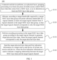
- FIG 1 is a schematic flowchart of a data transmission method 100 according to an embodiment of the present invention from a perspective of a transmit end device.
- the method 100 includes: S110: A transmit end device performs, at a physical layer, grouping processing on at least one piece of media access control MAC layer data that comes from a MAC layer, to determine at least one MAC layer data group.
- S120 Allocate, according to target bandwidth required by a target MAC layer data group and preset reference bandwidth of a logical channel, at least one target logical channel from N logical channels to the target MAC layer data group, so that the target logical channel corresponds to only the target MAC layer data group.
- S130 Perform encoding processing on the target MAC layer data group according to the target logical channel to generate target physical layer data, where the target logical channel corresponds to only the target physical layer data.
- S 140 Send the target physical layer data and first indication information to a target receive end device of at least one receive end device, where the first indication information is used to indicate a mapping relationship between the target MAC layer data and the target logical channel.
- the data transmission method 100 is mainly completed at the physical layer of the transmit end device. That is, when the physical layer receives a plurality of media access control (MAC, Medium Access Control) MAC layer data frames that comes from the MAC layer, the foregoing method 100 is executed to convert MAC layer data into physical layer data that complies with a format of data transmitted between Ethernet devices and to transmit the physical layer data.
- MAC media access control
- the physical layer includes a reconciliation sublayer and a physical coding sublayer.
- the reconciliation layer is used to perform conversion processing on data between the MAC and the physical layer.
- the physical coding sublayer which includes N logical channels is used to implement encoding processing on physical layer data.
- the physical layer further includes a media independent interface.
- the media independent interface is arranged between the reconciliation sublayer and the physical coding sublayer and used for data transmission between the reconciliation sublayer and the physical coding sublayer by using N timeslots, where one timeslot is used to transmit data in one logical channel.
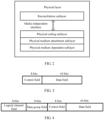
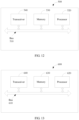
- FIG 2 is a schematic diagram of a physical layer structure according to an embodiment of the present invention.
- a physical layer of an Ethernet device may include: a reconciliation sublayer (RS, Reconciliation Sublayer), a physical coding sublayer (PCS, Physical Coding Sublayer), a media independent interface (MII, Media Independent Interface), a physical medium attachment (PMA, Physical Medium Attachment) sublayer, and a physical medium dependent (PMD, Physical Medium Dependent) sublayer.
- the reconciliation sublayer is used to perform reconciliation processing, convert an Ethernet frame (also known as a MAC layer data frame) into media independent interface data (an example of MAC layer data), and send the media independent interface data to the physical coding sublayer through the media independent interface.
- the physical coding sublayer performs encoding processing (for example, 64B/66B encoding), scrambling processing, and the like on the media independent interface data to generate a (for example, 66B) code block (an example of physical layer data), and delivers the code block to a logical channel.
- the physical medium attachment sublayer is used to implement multiplexing from a logical channel to a physical channel.
- the physical medium dependent sublayer is used to transmit the physical layer data through a physical channel.
- an Ethernet frame from the MAC layer may be converted into data (that is, MAC layer data) that complies with physical layer data transmission, where the MAC layer data may include 8 bits (bit) of control information and 64 bits of data.
- FIG 3 is a schematic diagram of a data format of media independent interface data (that is, MAC layer data) according to an embodiment of the present invention. As shown in FIG 3 , MAC layer data may include a control field and a data field. The control field is used to carry 8 bits of control information and the data field is used to carry 64 bits of data.
- grouping processing may be performed on MAC layer data.
- grouping method for example, MAC layer data may be divided by destination address, and MAC layer data with a same destination address is added to a same group.
- upper-layer data may be grouped (for example, by data type) at an upper layer (a layer above the MAC layer) in advance, and an Ethernet frame generated according to the grouped upper-layer data are sent to the physical layer in different time segments that are preset.
- MAC layer data converted from the Ethernet frame received within a same time segment may be added to a same group; or grouping may be performed according to a rule preset by an administrator or a group identifier added to the Ethernet frame (the group identifier indicates a group to which MAC layer data converted from the Ethernet frame belongs).
- the group identifier may be added at the MAC layer or an upper layer (a layer above the MAC layer) according to, for example, a service to which the data belongs.
- Ethernet frame may also be grouped first, and then format conversion processing is performed on the Ethernet frame by taking a group as a unit to directly obtain MAC layer data groups.
- bandwidth (target bandwidth) required by each MAC layer data group may be determined.
- the target bandwidth of each MAC layer data group may be determined according to a transmission rate of the MAC layer data group (that is, an amount of data of the MAC layer data group, which is received or sent within a unit time).
- the target bandwidth of each MAC layer data group may also be determined according to a bandwidth identifier added to an Ethernet frame (the bandwidth identifier indicates bandwidth required by MAC layer data converted from the Ethernet frame).
- the bandwidth identifier may be added at an upper layer (a layer above the MAC layer) according to, for example, a maximum bandwidth requirement of the data.
- a logical channel may be allocated to each MAC layer data group.
- this process may be implemented at the reconciliation sublayer (that is, case 1), or may be implemented at the physical coding sublayer (that is, case 2). The following describes the foregoing two cases separately.
- the allocating, according to target bandwidth required by a target MAC layer data group and preset reference bandwidth of a logical channel, at least one target logical channel to the target MAC layer data group includes:
- MAC layer data group A an example of the target MAC layer data group
- MAC layer data group B another example of the target MAC layer data group
- MAC layer data group Z still another example of the target MAC layer data group
- a traffic bandwidth requirement (target bandwidth) of the MAC layer data group A is 50 G
- a traffic bandwidth requirement (target bandwidth) of the MAC layer data group B is 25 G
- a traffic bandwidth requirement (target bandwidth) of the MAC layer data group Z is 50 G
- the MAC layer data group A corresponds to two logical channels (for example, a first logical channel and a second logical channel, which are referred to hereinafter as a logical channel 1 and a logical channel 2)
- the MAC layer data group B corresponds to one logical channel (for example, a third logical channel, which is referred to hereinafter as a logical channel 3)
- the MAC layer data group Z corresponds to two logical channels (for example, a fifteenth logical channel and a sixteenth logical channel, which are referred to hereinafter as a logical channel 15 and a logical channel 16).
- the reconciliation sublayer may send information (an example of the second indication information) indicating a logical channel corresponding to each piece of MAC layer data to the physical coding sublayer.
- the method further includes: sending, at the reconciliation sublayer, third indication information to the physical coding sublayer, where the third indication information is used to indicate the mapping relationship between the target MAC layer data group and the target logical channel.
- the reconciliation sublayer may send, to the physical coding sublayer, information (an example of the third indication information) used to indicate a MAC layer data group corresponding to each logical channel of the physical coding sublayer.
- the physical layer further includes a media independent interface.
- the media independent interface is arranged between the reconciliation sublayer and the physical coding sublayer and used for data transmission between the reconciliation sublayer and the physical coding sublayer by using N timeslots, where one timeslot is used to transmit data in one logical channel.
- data between the reconciliation sublayer and the physical coding sublayer is transmitted through the media independent interface.
- the media independent interface may use a time division multiplexing data transmission manner, that is, one period may be divided into N timeslots and the N timeslots correspond to N logical channels of the physical coding sublayer, that is, the media independent interface may transmit MAC layer data corresponding to only one logical channel in one timeslot.
- the first 8 bits of control information and 64 bits of data are placed in the first timeslot
- the second 8 bits of control information and 64 bits of data are placed in the second timeslot
- the third 8 bits of control information and 64 bits of data are placed in the first timeslot
- the fourth 8 bits of control information and 64 bits of data are placed in the second timeslot, and so on.
- the first 8 bits of control information and 64 bits of data are placed in the fifteenth timeslot
- the second 8 bits of control information and 64 bits of data are placed in the sixteenth timeslot
- the third 8 bits of control information and 64 bits of data are placed in the fifteenth timeslot
- the fourth 8 bits of control information and 64 bits of data are placed in the sixteenth timeslot, and so on.
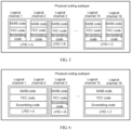
- FIG 4 is a schematic diagram of a data format of media independent interface data (that is, MAC layer data) according to another embodiment of the present invention.
- a logical channel field and a data group field may be added to a data format of MAC layer data.
- the logical channel field is used to carry second indication information indicating a logical channel corresponding to MAC layer data of a timeslot.
- the data group field is used to carry third indication information indicating a MAC layer data group to which the MAC layer data of the timeslot belongs.
- a logical channel field of the MAC layer data group A carries information indicating the first and second logical channels
- a data group field of the MAC layer data group A carries information indicating the data group A
- a logical channel field of the MAC layer data group B carries information indicating the third logical channel
- a data group field of the MAC layer data group B carries information indicating the data group B
- a logical channel field of the MAC layer data group Z carries information indicating the fifteenth and sixteenth logical channels
- a data group field of the MAC layer data group Z carries information indicating the data group Z.
- a sequence of the logical channel field and the data group field is not limited to that shown in FIG 4 as long as the logical channel field and the data group field are carried in the data format of MAC layer data.
- the second indication information, the third indication information, and the MAC layer data may also be sent separately in different time segments; or a transmission rule may be specified in advance so that timeslots of the media independent interface correspond to logical channels of the physical coding sublayer one to one, so that the reconciliation sublayer may select time for transmission according to a mapping relationship between the timeslots and the logical channels, and therefore the physical coding sublayer may determine, according to a timeslot of received MAC layer data, a logical channel corresponding to the MAC layer data. Therefore, the foregoing logical channel field may be omitted.
- the physical coding sublayer may determine, according to the second indication information, MAC layer data (MAC layer data received in a same timeslot) corresponding to each logical channel, and may determine, according to the third indication information, one or more logical channels corresponding to each MAC layer data group.
- the foregoing data group field may be omitted, and the physical coding sublayer considers by default that the logical channels correspond to only one same MAC layer data group.
- target bandwidth of the MAC layer data group is less (less than or equal to reference bandwidth of a logical channel)
- the MAC layer data group corresponds to only one logical channel. Therefore, the foregoing logical channel field may be omitted, and the physical coding sublayer may randomly allocate a logical channel to the MAC layer data group.
- the allocating, according to target bandwidth required by a target MAC layer data group and preset reference bandwidth of a logical channel, at least one target logical channel to the target MAC layer data group includes:
- the method further includes: sending, at the reconciliation sublayer, third indication information to the physical coding sublayer, where the third indication information is used to indicate the mapping relationship between the target MAC layer data group and the target logical channel.
- the reconciliation sublayer may send, to the physical coding sublayer, information (an example of the third indication information) used to indicate a MAC layer data group corresponding to each logical channel of the physical coding sublayer.
- the physical layer further includes a media independent interface.
- the media independent interface is arranged between the reconciliation sublayer and the physical coding sublayer and used for data transmission between the reconciliation sublayer and the physical coding sublayer by using N timeslots, where one timeslot is used to transmit data in one logical channel.
- data between the reconciliation sublayer and the physical coding sublayer is transmitted through the media independent interface.
- the media independent interface may use a periodic data transmission manner, that is, one period may be divided into N timeslots and the N timeslots correspond to N logical channels of the physical coding sublayer, in other words, in one timeslot, the media independent interface may transmit MAC layer data corresponding to only one logical channel.
- the first 8 bits of control information and 64 bits of data are placed in the first timeslot
- the second 8 bits of control information and 64 bits of data are placed in the second timeslot
- the third 8 bits of control information and 64 bits of data are placed in the first timeslot
- the fourth 8 bits of control information and 64 bits of data are placed in the second timeslot, and so on.
- the first 8 bits of control information and 64 bits of data are placed in the fifteenth timeslot
- the second 8 bits of control information and 64 bits of data are placed in the sixteenth timeslot
- the third 8 bits of control information and 64 bits of data are placed in the fifteenth timeslot
- the fourth 8 bits of control information and 64 bits of data are placed in the sixteenth timeslot, and so on.
- the third indication information may be included in MAC layer data and transmitted to the physical coding sublayer.
- FIG 4 is a schematic diagram of a data format of media independent interface data (that is, MAC layer data) according to another embodiment of the present invention. As shown in FIG 4 , a data group field may be added to a data format of MAC layer data. The data group field is used to carry third indication information indicating a MAC layer data group to which MAC layer data of a timeslot belongs.
- a target logical channel corresponding to each MAC layer data group is not determined at the RS layer, and therefore, a "logical channel field" shown in FIG 4 is not required in this embodiment, that is, the data format of media independent interface data (that is, MAC layer data) in this embodiment may include only the data group field, a control field, and a data field that are shown in FIG 4 .
- the physical coding sublayer may allocate, according to a received timeslot of each piece of MAC layer data, one same logical channel to MAC layer data received in a same timeslot, and therefore may determine, according to the third indication information, one or more logical channels corresponding to each MAC layer data group.
- the foregoing method for transmitting the third indication information is described merely as an example, and the present invention is not limited thereto.
- the third indication information and the MAC layer data may be sent separately in different time segments.
- the foregoing data group field may be omitted, and the physical coding sublayer considers by default that the logical channels correspond to only one same MAC layer data group.
- target bandwidth of the MAC layer data group is less (less than or equal to reference bandwidth of a logical channel)
- the MAC layer data group corresponds to only one logical channel. Therefore, the foregoing logical channel field may be omitted, and the physical coding sublayer may randomly allocate a logical channel to the MAC layer data group.
- encoding processing may be performed on data (a stream of 8 + 64 bits information) of each logical channel.
- the following method may be used as an example:
- 64B/66B encoding may be performed on the stream of 8 + 64 bits information (information in a control field and a data field) to form a 66B code block stream.
- forward error correction (FEC, Forward Error Correction) processing may be performed on the 66B code block stream; or encoding and compression processing may be performed again on 66B code blocks selectively, for example, every four 66B code blocks are encoded and converted into one 257B code block, and then FEC processing is performed on a 257B code block stream.
- FEC Forward Error Correction
- scrambling processing may be performed on a code block stream into which FEC check information is added.
- FEC check information For a 66B code block, a 2-bit synchronization header may not be involved in the scrambling processing.
- processes and methods of 64B/66B encoding processing, FEC processing, and scrambling processing may be the same as those in the prior art, and are not described herein to avoid repetition.
- the performing encoding processing on the target MAC layer data group according to the target logical channel to generate target physical layer data is specifically:
- 64B/66B encoding processing, FEC processing, and scrambling processing may be performed on the MAC layer data by taking a logical channel as a unit. In this case, it needs to be ensured that processing of logical channels corresponding to a same MAC layer data group is synchronized.
- overall 64B/66B encoding processing, FEC processing, and scrambling processing may be performed on code block streams of logical channels corresponding to a same MAC layer data group by taking a MAC data group as a unit.
- Performing encoding, FEC processing, and scrambling processing by taking a logical channel or a MAC data group as a unit can implement multi-channel processing and lower complexity of transmitting a high-rate service, thereby reducing hardware costs.
- an alignment marker (AM, Alignment Marker) may be inserted by taking a logical channel or a MAC layer data group as a unit.
- the AM is inserted based on a certain period, where the period is 16384 code blocks on each logical channel.
- Respective alignment markers are periodically inserted on logical channels, or respective alignment markers are periodically inserted on logical channels within a MAC layer data group at a same time.
- the AM is a special pattern. Alignment marker AM patterns inserted on logical channels are different and used for a receive end to differentiate the logical channels.
- a logical channel number can be identified by using a pattern of an alignment marker code block.
- data that complies with physical layer data transmission is generated. That is, by means of the foregoing process, physical layer data A corresponding to the foregoing MAC layer array A, physical layer data B corresponding to the foregoing MAC layer array B, and physical layer data C corresponding to the foregoing MAC layer array C are generated.
- the method further includes: sending the first indication information to the receive end device, where the first indication information is used to indicate the mapping relationship between the target MAC layer data and the target logical channel.
- the first indication information and the target physical layer data are carried in a same data packet; or the first indication information is sent independent of the target physical layer data.
- the transmit end device further needs to notify (by the first indication information) a receive end of a MAC layer data group corresponding to each logical channel.
- logic port identifier (LPID, Logic Port Identifier) information may be added to the foregoing added AM.
- LPID information added to logical channels corresponding to a same MAC layer data group is consistent, and LPID information added to logical channels corresponding to different MAC layer data groups varies. Therefore, the receive end device can differentiate a MAC layer data group corresponding to each logical channel by identifying LPID information of the logical channel.
- a 66B alignment code block is used as an example.
- Table 1 shows a 66B alignment marker according to an embodiment of the present invention.
- one AM may have 66 bits.
- Block synchronization header information 10 is placed in the first two bits, and the foregoing first indication information is placed in the LPID2 field and the LPID6 field.
- binary information content in the LPID2 field and the LPID6 field is bit-reversed.
- Check information of the logical channel is placed in the BIP3 field and the BIP7 field. Alignment pattern information of a logical channel is placed in the M0 field, M1 field, M4 field and M5 field.
- the foregoing method for transmitting the first indication information is described merely as an example, and the present invention is not limited thereto.
- the first indication information and the AM may be sent separately in different time segments.
- the foregoing LPID2 field and LPID6 field may be omitted, and the receive end considers by default that the logical channels correspond to only one same MAC layer data group.
- a transmit end device sends to a receive end device information indicating physical layer data (or each MAC layer data group) corresponding to each logical channel, which can enable a receive end device to easily determine logical channels corresponding to a same MAC layer data group.
- the physical medium attachment sublayer may multiplex to one or more physical channels the foregoing determined data corresponding to each logical channel.
- different MAC layer data groups (or physical layer data) may be multiplexed to different physical channels.
- one MAC layer data group may correspond to one or more physical channels.
- the transmit end device has a total of four physical channels and each channel has bandwidth of 100 G
- the logical channel 1 and the logical channel 2 corresponding to the MAC layer data group A may be multiplexed to one physical channel (for example, a physical channel 1).
- the logical channel 3 corresponding to the MAC layer data group B may be multiplexed to one physical channel (for example, a physical channel 2).
- the logical channel 15 and the logical channel 16 corresponding to the MAC layer data group Z may be multiplexed to one physical channel (for example, a physical channel 3).
- a multiplexing manner may be bit multiplexing.
- the number of logical channels may be an integer multiple of the number of physical channels, or reference bandwidth of a physical channel may be an integer multiple of reference bandwidth of a logical channel.
- reference bandwidth of a physical channel may be set to reference bandwidth of a logical channel, a same group of logical channels may be transmitted by using a same physical channel.
- a multi-carrier manner may be used to transmit to the receive end device the foregoing physical layer data that is multiplexed to each physical channel.
- the sending the target physical layer data to a target receive end device of at least one receive end device includes:
- one or more logical ports may be divided at the physical layer (specifically, the physical medium dependent sublayer), where one logical port may include one or more physical channels and physical channels included in different logical ports are different.
- the numbers of physical channels included in different logical ports may be the same or may be different, and the present invention poses no particular limitation thereon. It should be understood that the foregoing logical port dividing method is described merely as an example, and the present invention is not limited thereto.
- logical ports may also be divided based on the foregoing determined MAC layer data groups, so that one logical port corresponds to one MAC layer data group, or one logical port corresponds to a plurality of logical channels corresponding to a same MAC layer data group.
- a plurality of logical channels corresponding to a same logical port is multiplexed to at least one physical channel that belongs to the logical port.
- the transmit end device may connect to only one receive end device.
- the transmit end device may select, according to a rate requirement of the physical layer data (or target bandwidth of a corresponding MAC layer data group), reference bandwidth of each physical channel, and the number of physical channels included in each logical port, one logical port to perform the sending. For example, if the rate requirement of the physical layer data is 75 G and bandwidth of one physical channel is 25 G, a logical port including three physical channels may be selected to send the physical layer data.
- the transmit end device is communicatively connected to at least two receive end devices, and the transmit end device includes at least two logical ports, where one logical port corresponds to one receive end device.
- the transmit end device may divide a plurality of physical channels to a plurality of logical ports, and one logical port may correspond to only one receive end device, that is, the logical port is only used to transmit data that needs to be sent to the receive end device.
- one receive end device there may be a plurality of corresponding logical interfaces or there may be only one corresponding logical interface, and the present invention poses no particular limitation thereon.
- the determining, from at least one logical port, a target logical port that is used to transmit the target physical layer data includes: determining, from a preset mapping relationship between the at least two receive end devices and the at least two logical ports, the target logical port according to the target receive end device.
- the transmit end device may determine the mapping relationship between the logical ports and the receive end devices, and determine a logical port.
- physical layer data A (an example of target physical layer data) generated by a MAC layer data group A needs to be sent to a receive end device A; and then, a logical port A (an example of the target logical port) corresponding to the receive end device A may be selected and a physical channel corresponding to the logical port A is used to perform the sending.
- Physical layer data B (another example of the target physical layer data) generated by a MAC layer data group B needs to be sent to a receive end device B; and then, a logical port B (another example of the target logical port) corresponding to the receive end device B may be selected and a physical channel corresponding to the logical port B is used to perform the sending.
- Physical layer data Z (still another example of the target physical layer data) generated by a MAC layer data group Z needs to be sent to a receive end device Z; and then, a logical port Z (still another example of the target logical port) corresponding to the receive end device Z may be selected and a physical channel corresponding to the logical port Z is used to perform the sending.
- bandwidth of each logical port may be pre-determined according to a transmission rate supported by each receive end device, and a rate requirement (target bandwidth) of data that needs to be sent to a receive end device needs to be lower than the transmission rate supported by each receive end device, thereby ensuring that bandwidth of a selected logical port is greater than or equal to the rate requirement of the data that needs to be transmitted.
- the transmit end device may search a prestored mapping relationship between MAC layer addresses and the receive end devices, for example, a forwarding table, according to a destination MAC layer address of a MAC layer data group, to determine a receive end device to which each MAC layer data group (or target physical layer data generated after encoding processing is performed on the MAC layer data group) needs to be sent.
- a prestored mapping relationship between MAC layer addresses and the receive end devices for example, a forwarding table, according to a destination MAC layer address of a MAC layer data group, to determine a receive end device to which each MAC layer data group (or target physical layer data generated after encoding processing is performed on the MAC layer data group) needs to be sent.
- a physical port of a transmit end device may include a logical port A, a logical port B, and a logical port Z, where a service carried on the logical port A is transmitted by using a subcarrier A, a service carried on the logical port B is transmitted by using a subcarrier B, and a service carried on the logical port Z is transmitted by using a subcarrier Z, and be connected to a cross node by using a same optical fiber (specifically, the subcarrier A, the subcarrier B, and the subcarrier Z).
- the cross node may be a wavelength cross processing node and may schedule a plurality of subcarriers to different directions.
- the subcarrier A, the subcarrier B, and the subcarrier Z are scheduled to a receive end device A, a receive end device B, and a receive end device Z respectively.
- a configuration command may be delivered by a network management system in advance to determine a scheduling direction of each subcarrier, that is, it may be specified by the network management system in advance that the subcarrier A, the subcarrier B, and the subcarrier Z are scheduled to the receive end device A, the receive end device B, and the receive end device Z respectively.
- a plurality of physical channels is divided at a same time to form a plurality of logical ports, so that data can be sent to different receive end devices through different ports, which can implement point-to-multipoint data transmission, thereby communication flexibility of an Ethernet communications system is greatly improved.
- optical carrier scheduling is used, which, compared with the prior art, which can put an optical subcarrier that is temporarily unneeded to sleep or disable the optical subcarrier, thereby reducing power consumption and saving energy.
- the number of physical channels included in each logical port varies, which can adapt one Ethernet device to data transmission with a plurality of rate requirements, thereby improving adaptability and communication flexibility of the Ethernet device and saving device costs.
- a receive end device may process, at the physical layer, the physical layer data to acquire MAC layer data.
- a physical layer of an Ethernet device (the transmit end device) in this embodiment of the present invention may include: a reconciliation sublayer, a physical coding sublayer, a media independent interface, a physical medium attachment sublayer, and a physical medium dependent sublayer.
- the physical medium dependent sublayer is used to receive, through a physical channel, physical layer data sent by a transmit end.
- the physical medium attachment sublayer is used to implement demultiplexing from a physical channel to a logical channel.
- the physical coding sublayer is used to deliver physical layer data to a logical channel and perform decoding processing (for example, 64B/66B decoding), descrambling processing, and the like on the physical layer data to generate media independent interface data.
- the reconciliation sublayer is used to perform reconciliation processing and convert media independent interface data into an Ethernet frame.
- the receive end device may demultiplex the physical channel to restore all physical layer data.
- a logical channel corresponding to each piece of physical layer data may be determined, and the physical layer data is processed according to the logical channel to acquire MAC layer data.
- code block synchronization header searching processing may be performed for each logical channel to determine a code block border
- the Flex MII interface data may be converted into an Ethernet frame that needs to be sent to the MAC layer.
- the receive end device in a case in which the physical layer data is generated after the transmit end device performs processing such as encoding on a plurality of MAC layer data groups, the receive end device further needs to determine a MAC layer data group corresponding to each logical channel.
- the transmit end may add an LPID field to an AM to carry the first indication information. Therefore, the receive end device may extract and compare LPIDs in AMs of the logical channels to determine the MAC layer data groups (or a combination manner of the logical channels) corresponding to the logical channels.
- grouping is performed on MAC layer data and a logical channel is allocated to each MAC layer data group according to a rate of each MAC layer data group, to perform encoding processing and transmission processing on each MAC layer data group according to the allocated logical channel, which can meet a requirement for an Ethernet network with diversified rate levels and implement interconnection between Ethernet interfaces of different rate levels.
- a logical channel is allocated according to bandwidth required by a MAC layer data group, which, compared with the prior art, can put a logical channel that is temporarily unneeded to sleep or disable the logical channel when a bandwidth requirement of MAC layer data is low, thereby reducing power consumption and saving energy.
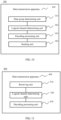
- FIG 9 is a schematic flowchart of a data transmission method 200 according to an embodiment of the present invention from a perspective of a receive end device.
- the method 200 includes: S210: A receive end device receives, at a physical layer, target physical layer data and first indication information that are sent by a target transmit end device of at least one transmit end device.
- S220 Determine, from N logical channels according to the first indication information, at least one target logical channel that corresponds to only a target media access control MAC layer data group, where the first indication information is used to indicate a mapping relationship between the MAC layer data group and the target logical channel, the target MAC layer data group is determined after the target transmit end device performs grouping processing on at least one piece of MAC layer data that comes from a MAC layer, and the target logical channel is allocated by the target transmit end device according to target bandwidth required by the target MAC layer data group and preset reference bandwidth of a logical channel.
- S230 Perform decoding processing on the target physical layer data according to the target logical channel to acquire the target MAC layer data group.
- the receive end device may receive the target physical layer data, where the target physical layer data may be generated and sent in the following manner by the target transmit end device that is communicatively connected to the receive end device, that is: when receiving a plurality of media access control (MAC, Medium Access Control) layer data frames that come from the MAC layer, a physical layer of the target transmit end device may covert the MAC layer data into physical layer data that complies with a format of data transmitted between Ethernet devices.
- MAC media access control
- the target transmit end device may convert, at a reconciliation sublayer, Ethernet frames that come from the MAC layer into data (that is, MAC layer data) that complies with physical layer data transmission, where the MAC layer data may include 8 bits (bit) of control information and 64 bits of data.
- MAC layer data may include a control field and a data field. The control field is used to carry 8 bits of control information and the data field is used to carry 64 bits of data.
- the target transmit end device may perform grouping processing on MAC layer data.
- grouping processing for example, MAC layer data may be divided by destination address, and MAC layer data with a same destination address is added to a same group.
- the target transmit end device may determine bandwidth (target bandwidth) required by each MAC layer data group.
- the target bandwidth of each MAC layer data group may be determined according to a transmission rate of the MAC layer data group (that is, an amount of data of the MAC layer data group, which is received or sent within a unit time).
- the target transmit end device may allocate a logical channel to each MAC layer data group.
- this process may be implemented at the reconciliation sublayer, or may be implemented at a physical coding sublayer.
- MAC layer data group A an example of the target MAC layer data group
- MAC layer data group B another example of the target MAC layer data group
- MAC layer data group Z still another example of the target MAC layer data group
- a traffic bandwidth requirement (target bandwidth) of the MAC layer data group A is 50 G
- a traffic bandwidth requirement (target bandwidth) of the MAC layer data group B is 25 G
- a traffic bandwidth requirement (target bandwidth) of the MAC layer data group Z is 50 G
- the target transmit end device may determine that the MAC layer data group A corresponds to two logical channels (for example, a first logical channel and a second logical channel, which are referred to hereinafter as a logical channel 1 and a logical channel 2), the MAC layer data group B corresponds to one logical channel (for example, a third logical channel, which is referred to hereinafter as a logical channel 3), and the MAC layer data group Z corresponds to two logical channels (for example, a fifteenth logical channel and a sixteenth logical channel, which are referred to hereinafter as a logical channel 15 and a logical channel 16).
- a first logical channel and a second logical channel which are referred to hereinafter as a logical channel 1 and a logical channel 2
- the MAC layer data group B corresponds to one logical channel (for example, a third logical channel, which is referred to hereinafter as a logical channel 3)
- the MAC layer data group Z corresponds to
- the reconciliation sublayer may send information (an example of second indication information) indicating a logical channel corresponding to each piece of MAC layer data to the physical coding sublayer.
- the reconciliation sublayer may send, to the physical coding sublayer, information (an example of third indication information) used to indicate a MAC layer data group corresponding to each logical channel of the physical coding sublayer.
- data between the reconciliation sublayer and the physical coding sublayer may be transmitted through a media independent interface.
- the media independent interface may use a time division multiplexing data transmission manner, that is, one period may be divided into N timeslots and the N timeslots correspond to N logical channels of the physical coding sublayer, in other words, in one timeslot, the media independent interface may transmit MAC layer data corresponding to only one logical channel .
- the media independent interface may transmit MAC layer data corresponding to only one logical channel .
- the first 8 bits of control information and 64 bits of data are placed in the first timeslot
- the second 8 bits of control information and 64 bits of data are placed in the second timeslot
- the third 8 bits of control information and 64 bits of data are placed in the first timeslot
- the fourth 8 bits of control information and 64 bits of data are placed in the second timeslot, and so on.
- the second indication information and the third indication information may be included in MAC layer data and transmitted to the physical coding sublayer at a same time.
- FIG 4 is a schematic diagram of a data format of media independent interface data (that is, MAC layer data) according to another embodiment of the present invention.
- a logical channel field and a data group field may be added to a data format of MAC layer data.
- the logical channel field is used to carry second indication information indicating a logical channel corresponding to MAC layer data of a timeslot.
- the data group field is used to carry third indication information indicating a MAC layer data group to which the MAC layer data of the timeslot belongs.
- the transmit end device may determine, according to the second indication information, MAC layer data (MAC layer data received in a same timeslot) corresponding to each logical channel, and may determine, according to the third indication information, one or more logical channels corresponding to each MAC layer data group.
- MAC layer data MAC layer data received in a same timeslot
- the transmit end device may determine at the reconciliation sublayer that the MAC layer data group A corresponds to two logical channels, the MAC layer data group B corresponds to one logical channel, and the MAC layer data group Z corresponds to two logical channels.
- the reconciliation sublayer may send, to the physical coding sublayer, information (an example of third indication information) used to indicate a MAC layer data group corresponding to each logical channel of the physical coding sublayer.
- data between the reconciliation sublayer and the physical coding sublayer is transmitted through a media independent interface.
- the media independent interface may use a time division multiplexing (or periodic) data transmission manner, that is, one period may be divided into N timeslots and the N timeslots correspond to N logical channels of the physical coding sublayer, in other words, the media independent interface may transmit MAC layer data corresponding to only one logical channel in one timeslot.
- the media independent interface may transmit MAC layer data corresponding to only one logical channel in one timeslot.
- the first 8 bits of control information and 64 bits of data are placed in the first timeslot
- the second 8 bits of control information and 64 bits of data are placed in the second timeslot
- the third 8 bits of control information and 64 bits of data are placed in the first timeslot
- the fourth 8 bits of control information and 64 bits of data are placed in the second timeslot, and so on.
- FIG 4 is a schematic diagram of a data format of media independent interface data (that is, MAC layer data) according to another embodiment of the present invention.
- a data group field may be added to a data format of MAC layer data.
- the data group field is used to carry third indication information indicating a MAC layer data group to which MAC layer data of the timeslot belongs. Therefore, at the physical coding sublayer, the transmit end device may allocate, according to a received timeslot of each piece of MAC layer data, a same logical channel to MAC layer data received within a same timeslot, and therefore may determine, according to the third indication information, one or more logical channels corresponding to each MAC layer data group.
- the target transmit end device may perform encoding processing on data (a stream of 8 + 64 bits information) of each logical channel. For example, first, 64B/66B encoding may be performed on the stream of 8 + 64 bits information (information in a control field and a data field) to form a 66B code block stream; after that, forward error correction (FEC, Forward Error Correction) processing may be performed on the 66B code block stream; or encoding and compression processing may be performed again on 66B code blocks selectively, for example, every four 66B code blocks are encoded and converted into one 257B code block, and then FEC processing is performed on a 257B code block stream; and finally, scrambling processing may be performed on a code block stream into which FEC check information is added.
- FEC Forward Error Correction
- a 2-bit synchronization header may not be involved in the scrambling processing.
- 64B/66B encoding processing, FEC processing, and scrambling processing may be performed on the MAC layer data by taking a logical channel as a unit. In this case, it needs to be ensured that processing of logical channels corresponding to a same MAC layer data group is synchronized.
- overall 64B/66B encoding processing, FEC processing, and scrambling processing may be performed on code block streams of logical channels corresponding to a same MAC layer data group by taking a MAC data group as a unit.
- an alignment marker (AM, Alignment Marker) may be inserted by taking a MAC layer data group as a unit.
- the AM is inserted based on a certain period, where the period is 16384 code blocks on each logical channel. Respective alignment markers are periodically inserted on logical channels within a MAC layer data group at a same time.
- the AM is a special pattern. Alignment marker AM patterns inserted on logical channels are different and used for a receive end to differentiate the logical channels. A logical channel number can be identified by using a pattern of an alignment marker code block.
- data that complies with physical layer data transmission is generated. That is, by means of the foregoing process, physical layer data A corresponding to the foregoing MAC layer array A, physical layer data B corresponding to the foregoing MAC layer array B, and physical layer data C corresponding to the foregoing MAC layer array C are generated.
- the target transmit end device may multiplex to one or more physical channels the foregoing determined data corresponding to each logical channel.
- different MAC layer data groups (or physical layer data) may be multiplexed to different physical channels.
- one MAC layer data group may correspond to one or more physical channels. For example, it is assumed that the transmit end device has a total of four physical channels and each channel has bandwidth of 100 G
- the logical channel 1 and the logical channel 2 corresponding to the MAC layer data group A may be multiplexed to one physical channel (for example, a physical channel 1).
- the logical channel 3 corresponding to the MAC layer data group B may be multiplexed to one physical channel (for example, a physical channel 2).
- the logical channel 15 and the logical channel 16 corresponding to the MAC layer data group Z may be multiplexed to one physical channel (for example, a physical channel 3).
- a multiplexing manner may be bit multiplexing.
- the target transmit end device may use a multi-carrier manner to transmit to the receive end device the foregoing physical layer data (including the target physical layer data) that is multiplexed to each physical channel.
- the receive end device may receive, through a physical channel, the target physical layer data sent by the target transmit end device.
- the receive end device may demultiplex the physical channel to restore all physical layer data. It should be noted that, in this embodiment of the present invention, in a case in which the physical layer data is generated after the transmit end device performs processing such as encoding on a plurality of MAC layer data groups, the receive end device further needs to determine a MAC layer data group corresponding to each logical channel. That is:
- the determining, from N logical channels, at least one target logical channel that corresponds to only the target physical layer data includes:
- the first indication information and the target physical layer data are carried in a same data packet; or the first indication information is sent independent of the target physical layer data.
- a target transmit end acquires a plurality of MAC layer data groups (the MAC layer data group A, the MAC layer data group B, and the MAC layer data group Z)
- the target transmit end device further needs to notify (by the first indication information) a receive end of a MAC layer data group corresponding to each logical channel.
- logic port identifier (LPID, Logic Port Identifier) information may be added to the foregoing added AM. LPID information added to logical channels corresponding to a same MAC layer data group is consistent, and LPID information added to logical channels corresponding to different MAC layer data groups varies.
- the receive end device can differentiate a MAC layer data group corresponding to each logical channel by identifying LPID information of the logical channel.
- a 66B alignment code block is used as an example. As shown in Table 1, there are a total of 66 bits. Block synchronization header information 10 is placed in the first two bits, and the foregoing first indication information is placed in the LPID2 field and the LPID6 field. Binary information content in the LPID2 field and the LPID6 field is bit-reversed. Check information of the logical channel is placed in the BIP3 field and the BIP7 field. Alignment pattern information of a logical channel is placed in the M0 field, M1 field, M4 field and M5 field.
- An LPID field may be added to an AM to carry the first indication information. Therefore, the receive end device may extract and compare LPIDs in AMs of the logical channels to determine the MAC layer data groups (or a combination manner of the logical channels) corresponding to the logical channels.
- the foregoing method for transmitting the first indication information is described merely as an example, and the present invention is not limited thereto.
- the first indication information and the AM may be sent separately in different time segments.
- the foregoing LPID2 field and LPID6 field may be omitted, and the receive end considers by default that the logical channels correspond to only one same MAC layer data group.
- the physical layer includes a reconciliation sublayer and a physical coding sublayer
- the receive end device may perform code block synchronization header searching processing separately for each logical channel to determine a code block border;
- the Flex MII interface data may be converted into an Ethernet frame that needs to be sent to the MAC layer.
- the physical layer further includes a media independent interface, where the media independent interface is arranged between the reconciliation sublayer and the physical coding sublayer and used for data transmission between the reconciliation sublayer and the physical coding sublayer by using N timeslots, where one timeslot is used to transmit data in one logical channel; and the sending, at the physical coding sublayer, the target MAC layer data group to the reconciliation sublayer according to the target logical channel includes:
- data between the reconciliation sublayer and the physical coding sublayer may be transmitted through the media independent interface.
- the media independent interface may use a time division multiplexing data transmission manner, that is, one period may be divided into N timeslots and the N timeslots correspond to N logical channels of the physical coding sublayer, that is, the media independent interface may transmit MAC layer data corresponding to only one logical channel in one timeslot.
- the first 8 bits of control information and 64 bits of data are placed in the first timeslot
- the second 8 bits of control information and 64 bits of data are placed in the second timeslot
- the third 8 bits of control information and 64 bits of data are placed in the first timeslot
- the fourth 8 bits of control information and 64 bits of data are placed in the second timeslot, and so on.
- the first 8 bits of control information and 64 bits of data are placed in the fifteenth timeslot
- the second 8 bits of control information and 64 bits of data are placed in the sixteenth timeslot
- the third 8 bits of control information and 64 bits of data are placed in the fifteenth timeslot
- the fourth 8 bits of control information and 64 bits of data are placed in the sixteenth timeslot, and so on.
- the performing decoding processing on the target physical layer data according to the target logical channel to acquire the target media access control MAC layer data group includes:
- the physical coding sublayer may send, to the reconciliation sublayer, information used to indicate a MAC layer data group corresponding to each logical channel of the physical coding sublayer (an example of the third indication information). Therefore, the reconciliation sublayer may determine, according to the second indication information, MAC layer data (MAC layer data received in a same timeslot) corresponding to each logical channel, and may determine, according to the third indication information, one or more logical channels corresponding to each MAC layer data group.
- the reconciliation sublayer may determine, according to the second indication information, MAC layer data (MAC layer data received in a same timeslot) corresponding to each logical channel, and may determine, according to the third indication information, one or more logical channels corresponding to each MAC layer data group.
- one or more logical ports may be divided at the physical layer (specifically, the physical medium dependent sublayer), where one logical port may include one or more physical channels and physical channels included in different logical ports are different.
- the numbers of physical channels included in different logical ports may be the same or may be different, and the present invention poses no particular limitation thereon.
- the receive end device may divide a plurality of physical channels to a plurality of logical ports, and one logical port may correspond to only one transmit end device, that is, the logical port is only used to transmit data that needs to come from the transmit end device.
- one transmit end device may have a plurality of corresponding logical interfaces or may have only one corresponding logical interface, and the present invention poses no particular limitation thereon.
- a plurality of physical channels is divided to form a plurality of logical ports, so that data sent by different transmit end devices can be received through different ports, which can implement point-to-multipoint data transmission, thereby greatly improving communication flexibility of an Ethernet communications system.
- the number of physical channels included in each logical port varies, which can adapt one Ethernet device to data transmission with a plurality of rate requirements, thereby improving adaptability and communication flexibility of the Ethernet device and saving device costs.
- grouping is performed on MAC layer data and a logical channel is allocated to each MAC layer data group according to a rate of each MAC layer data group, to perform encoding processing and transmission processing on each MAC layer data group according to the allocated logical channel, which can meet a requirement for an Ethernet network with diversified rate levels and implement interconnection between Ethernet interfaces of different rate levels.
- a logical channel is allocated according to bandwidth required by a MAC layer data group, which, compared with the prior art, can put a logical channel that is temporarily unneeded to sleep or disable the logical channel when a bandwidth requirement of MAC layer data is low, thereby reducing power consumption and saving energy.
- FIG 10 is a schematic block diagram of a data transmission apparatus 300 according to an embodiment of the present invention. As shown in FIG 10 , the apparatus 300 includes:
- the sending unit 340 is specifically configured to determine a target logical port from at least one logical port, where one logical port corresponds to at least one physical channel; and send the target physical layer data to the target receive end device through a physical channel corresponding to the target logical port.
- the transmit end device is communicatively connected to at least two receive end devices, and the transmit end device includes at least two logical ports, where one logical port corresponds to one receive end device; and the sending unit 340 is specifically configured to determine, from a preset mapping relationship between the at least two receive end devices and the at least two logical ports, the target logical port according to the target receive end device.
- the physical layer includes a reconciliation sublayer and a physical coding sublayer
- the physical layer includes a reconciliation sublayer, a media independent interface, and a physical coding sublayer, where the media independent interface is arranged between the reconciliation sublayer and the physical coding sublayer and used for data transmission between the reconciliation sublayer and the physical coding sublayer by using N timeslots, where one timeslot is used to transmit data in one logical channel; and
- the encoding processing unit 330 is specifically configured to perform, at the physical coding sublayer, encoding processing on the target MAC layer data group according to the target logical channel.
- the logical channel determining unit 320 is specifically configured to send, at the reconciliation sublayer, third indication information to the physical coding sublayer, where the third indication information is used to indicate the mapping relationship between the target MAC layer data group and the target logical channel.
- the encoding processing unit 330 is specifically configured to perform encoding processing on the target MAC layer data group by taking a target logical channel as a unit to generate the target physical layer data.
- the encoding processing unit 330 is specifically configured to take the target logical channel corresponding to the target MAC layer data group as one group, and perform encoding processing on the target MAC layer data group by taking a group as a unit, to generate the target physical layer data.
- the first indication information and the target physical layer data are carried in a same data packet; or the first indication information is sent independent of the target physical layer data.
- the data transmission apparatus 300 may correspond to the transmit end device (or the target transmit end device) in the method in the embodiments of the present invention.
- the units, that is, the modules, in the data transmission apparatus 300 and the foregoing other operations and/or functions are intended to implement a corresponding procedure of the method 100 in FIG 1 , which are not described herein again for brevity.
- grouping is performed on MAC layer data and a logical channel is allocated to each MAC layer data group according to a rate of each MAC layer data group, to perform encoding processing and transmission processing on each MAC layer data group according to the allocated logical channel, which can meet a requirement for an Ethernet network with diversified rate levels and implement interconnection between Ethernet interfaces of different rate levels.
- a logical channel is allocated according to bandwidth required by a MAC layer data group, which, compared with the prior art, can put a logical channel that is temporarily unneeded to sleep or disable the logical channel when a bandwidth requirement of MAC layer data is low, thereby reducing power consumption and saving energy.
- FIG 11 is a schematic block diagram of a data transmission apparatus 400 according to an embodiment of the present invention. As shown in FIG 11 , the apparatus 400 includes:
- the first indication information and the target physical layer data are carried in a same data packet; or the first indication information is sent independent of the target physical layer data.
- the physical layer includes a reconciliation sublayer and a physical coding sublayer
- the physical layer further includes a media independent interface, where the media independent interface is arranged between the reconciliation sublayer and the physical coding sublayer and used for data transmission between the reconciliation sublayer and the physical coding sublayer by using N timeslots, where one timeslot is used to transmit data in one logical channel; and
- the decoding processing unit 430 is specifically configured to perform, at the physical coding sublayer, decoding processing on the target physical layer data according to the target logical channel to acquire the target media access control MAC layer data group;
- the decoding processing unit 430 is specifically configured to take the target logical channel corresponding to the target physical layer data as one group, and perform decoding processing on the target physical layer data group by taking a group as a unit, to generate the target MAC layer data group.
- the data transmission apparatus 400 may correspond to the receive end device (or the target receive end device) in the method in the embodiments of the present invention.
- the units, that is, the modules, in the data transmission apparatus 400 and the foregoing other operations and/or functions are intended to implement a corresponding procedure of the method 200 in FIG 9 , which are not described herein again for brevity.
- grouping is performed on MAC layer data and a logical channel is allocated to each MAC layer data group according to a rate of each MAC layer data group, to perform encoding processing and transmission processing on each MAC layer data group according to the allocated logical channel, which can meet a requirement for an Ethernet network with diversified rate levels and implement interconnection between Ethernet interfaces of different rate levels.
- a logical channel is allocated according to bandwidth required by a MAC layer data group, which, compared with the prior art, can put a logical channel that is temporarily unneeded to sleep or disable the logical channel when a bandwidth requirement of MAC layer data is low, thereby reducing power consumption and saving energy.
- FIG 12 is a schematic block diagram of a data transmission device 500 according to an embodiment of the present invention. As shown in FIG 12 , the device 500 includes:
- the processor 520 invokes, through the bus 510, a program stored in the memory 530 to perform, at a physical layer, grouping processing on at least one piece of MAC layer data that comes from a media access control MAC layer, to determine at least one MAC layer data group;
- the first indication information and the target physical layer data are carried in a same data packet; or the first indication information is sent independent of the target physical layer data.
- the processor 520 is specifically configured to determine a target logical port from at least one logical port, where one logical port corresponds to at least one physical channel; and control the transceiver 540 to send, through a physical channel corresponding to the target logical port, the target physical layer data to the target receive end device.
- the transmit end device is communicatively connected to at least two receive end devices, and the transmit end device includes at least two logical ports, where one logical port corresponds to one receive end device; and the processor 520 is specifically configured to determine, from a preset mapping relationship between the at least two receive end devices and the at least two logical ports, the target logical port according to the target receive end device.
- the physical layer includes a reconciliation sublayer and a physical coding sublayer
- the physical layer includes a reconciliation sublayer, a media independent interface, and a physical coding sublayer, where the media independent interface is arranged between the reconciliation sublayer and the physical coding sublayer and used for data transmission between the reconciliation sublayer and the physical coding sublayer by using N timeslots, where one timeslot is used to transmit data in one logical channel; and
- the processor 520 is further configured to send, at the reconciliation sublayer, third indication information to the physical coding sublayer, where the third indication information is used to indicate a mapping relationship between the target MAC layer data group and the target logical channel.
- the processor 520 is specifically configured to take the target logical channel corresponding to the target MAC layer data group as one group, and perform encoding processing on the target MAC layer data group by taking a group as a unit, to generate the target physical layer data.
- the processor 520 may be a central processing unit (Central Processing Unit, "CPU” for short), or the processor 520 may be any other general-purpose processor, a digital signal processor (DSP), an application specific integrated circuit (ASIC), a field-programmable gate array (FPGA) or any other programmable logic device, a discrete gate or a transistor logic device, a discrete hardware component, or the like.
- the general-purpose processor may be a microprocessor, or the processor may be any conventional processor or the like.
- the memory 530 may include a read-only memory 530 and a random access memory 530, and provide an instruction and data for the processor 520. A part of the memory 530 may further include a non-volatile random access memory 530. For example, the memory 530 may further store information about a device type.
- the bus 510 may further include a power bus, a control bus, a status signal bus, and the like. However, for clear description, all buses are marked as the bus 510 in the figure.
- the steps in the foregoing method may be completed by an integrated logic circuit of hardware in the processor 520 or an instruction in a form of software.
- the steps of the method disclosed with reference to the embodiments of the present invention may be executed directly by the hardware processor 520, or may be executed by a combination of hardware and a software module in the processor 520.
- the software module may be located in a mature storage medium in the art, such as a random memory, a flash memory, a read-only memory, a programmable read-only memory, an electrically erasable programmable memory, or a register.
- the storage medium is located in the memory 530.
- the processor 520 reads information in the memory 530 and completes the steps in the foregoing method in combination with the hardware of the processor 520. To avoid repetition, details are not described herein again.
- the data transmission device 500 may correspond to the transmit end device (or the target transmit end device) in the method in the embodiments of the present invention.
- the units, that is, the modules, in the data transmission device 500 and the foregoing other operations and/or functions are intended to implement a corresponding procedure of the method 100 in FIG 1 , which are not described herein again for brevity.
- grouping is performed on MAC layer data and a logical channel is allocated to each MAC layer data group according to a rate of each MAC layer data group, to perform encoding processing and transmission processing on each MAC layer data group according to the allocated logical channel, which can meet a requirement for an Ethernet network with diversified rate levels and implement interconnection between Ethernet interfaces of different rate levels.
- a logical channel is allocated according to bandwidth required by a MAC layer data group, which, compared with the prior art, can put a logical channel that is temporarily unneeded to sleep or disable the logical channel when a bandwidth requirement of MAC layer data is low, thereby reducing power consumption and saving energy.
- FIG 13 is a schematic block diagram of a data transmission device 600 according to an embodiment of the present invention. As shown in FIG 13 , the device 600 includes:
- the processor 620 invokes, through the bus 610, a program stored in the memory 630 to control the transceiver 640 to receive, at a physical layer, target physical layer data and first indication information that are sent by a target transmit end device of at least one transmit end device;
- the first indication information and the target physical layer data are carried in a same data packet; or the first indication information is sent independent of the target physical layer data.
- the physical layer includes a reconciliation sublayer and a physical coding sublayer
- the physical layer further includes a media independent interface, where the media independent interface is arranged between the reconciliation sublayer and the physical coding sublayer and used for data transmission between the reconciliation sublayer and the physical coding sublayer by using N timeslots, where one timeslot is used to transmit data in one logical channel; and
- the processor 620 is specifically configured to perform, at the physical coding sublayer, decoding processing on the target physical layer data according to the target logical channel to acquire the target media access control MAC layer data group;
- the processor 620 is specifically configured to take the target logical channel corresponding to the target physical layer data as one group, and perform decoding processing on the target physical layer data group by taking a group as a unit, to generate the target MAC layer data group.
- the processor 620 may be a central processing unit (Central Processing Unit, "CPU” for short), or the processor 620 may be any other general-purpose processor, a digital signal processor (DSP), an application specific integrated circuit (ASIC), a field-programmable gate array (FPGA) or any other programmable logic device, a discrete gate or a transistor logic device, a discrete hardware component, or the like.
- the general-purpose processor may be a microprocessor, or the processor may be any conventional processor or the like.
- the memory 630 may include a read-only memory 630 and a random access memory 630, and provide an instruction and data for the processor 620610. A part of the memory 630 may further include a non-volatile random access memory 630. For example, the memory 630 may further store information about a device type.
- the bus 610 may further include a power bus, a control bus, a status signal bus, and the like. However, for clear description, all buses are marked as the bus 610 in the figure.
- the steps in the foregoing method may be completed by an integrated logic circuit of hardware in the processor 620 or an instruction in a form of software.
- the steps of the method disclosed with reference to the embodiments of the present invention may be executed directly by the hardware processor 620, or may be executed by a combination of hardware and a software module in the processor 620.
- the software module may be located in a mature storage medium in the art, such as a random memory, a flash memory, a read-only memory, a programmable read-only memory, an electrically erasable programmable memory, or a register.
- the storage medium is located in the memory 630.
- the processor 620 reads information in the memory 630 and completes the steps in the foregoing method in combination with the hardware of the processor 620. To avoid repetition, details are not described herein again.
- the data transmission device 600 may correspond to the receive end device (or the target receive end device) in the method in the embodiments of the present invention.
- the units, that is, the modules, in the data transmission device 600 and the foregoing other operations and/or functions are intended to implement a corresponding procedure of the method 200 in FIG 9 , which are not described herein again for brevity.
- grouping is performed on MAC layer data and a logical channel is allocated to each MAC layer data group according to a rate of each MAC layer data group, to perform encoding processing and transmission processing on each MAC layer data group according to the allocated logical channel, which can meet a requirement for an Ethernet network with diversified rate levels and implement interconnection between Ethernet interfaces of different rate levels.
- a logical channel is allocated according to bandwidth required by a MAC layer data group, which, compared with the prior art, can put a logical channel that is temporarily unneeded to sleep or disable the logical channel when a bandwidth requirement of MAC layer data is low, thereby reducing power consumption and saving energy.
- each Ethernet device in an Ethernet communications system may integrate functions of both a transmit end device and a receive end device in the embodiments of the present invention, or a single Ethernet device may execute both the data transmission method 100 and the data transmission method 200 in the embodiments of the present invention, and the present invention poses no particular limitation thereon.
- sequence numbers of the foregoing processes do not mean execution sequences.
- the execution sequences of the processes should be determined according to functions and internal logic of the processes, and should not be construed as any limitation on the implementation processes of the embodiments of the present invention.
- the disclosed system, apparatus, and method may be implemented in other manners.
- the described apparatus embodiment is merely exemplary.
- the unit division is merely logical function division and may be other division in actual implementation.
- a plurality of units or components may be combined or integrated into another system, or some features may be ignored or not performed.
- the displayed or discussed mutual couplings or direct couplings or communication connections may be implemented through some interfaces.
- the indirect couplings or communication connections between the apparatuses or units may be implemented in electronic, mechanical, or other forms.
- the units described as separate parts may or may not be physically separate, and parts displayed as units may or may not be physical units, may be located in one position, or may be distributed on a plurality of network units. A part or all of the units may be selected according to actual needs to achieve the objectives of the solutions of the embodiments.
- functional units in the embodiments of the present invention may be integrated into one processing unit, or each of the units may exist alone physically, or two or more units are integrated into one unit.
- the functions When the functions are implemented in a form of a software functional unit and sold or used as an independent product, the functions may be stored in a computer-readable storage medium. Based on such an understanding, the technical solutions of the present invention essentially, or the part contributing to the prior art, or a part of the technical solutions may be implemented in a form of a software product.
- the software product is stored in a storage medium, and includes several instructions for instructing a computer device (which may be a personal computer, a server, or a network device) to perform all or a part of the steps of the methods described in the embodiments of the present invention.
- the foregoing storage medium includes: any medium that can store program code, such as a USB flash drive, a removable hard disk, a read-only memory (ROM, Read-Only Memory), a random access memory (RAM, Random Access Memory), a magnetic disk, or an optical disc.
- program code such as a USB flash drive, a removable hard disk, a read-only memory (ROM, Read-Only Memory), a random access memory (RAM, Random Access Memory), a magnetic disk, or an optical disc.
Claims (15)
- Procédé de transmission de données, dans lequel le procédé est réalisé par une couche physique d'Ethernet d'un dispositif de transmission et comprend :l'obtention de données de couche de contrôle d'accès au support, MAC ;l'attribution, selon une largeur de bande requise par les données de couche de MAC et une largeur de bande de référence d'un canal logique, d'au moins un canal logique parmi N canaux logiques, dans lequel de multiples canaux logiques sont multiplexés par répartition dans le temps sur un canal physique, et dans lequel N est un nombre entier relatif non inférieur à 2 ;la génération de données de couche physique cibles en encodant les données de couche de MAC selon l'au moins un canal logique ; etl'envoi des données de couche physique cibles et de premières informations d'indication à un dispositif de réception cible, dans lequel les premières informations d'indication indiquent une relation de mappage entre les données de couche de MAC et l'au moins un canal logique et les premières informations d'indication différencient les données de couche de MAC transportées dans chaque canal logique des N canaux logiques.
- Procédé selon la revendication 1, dans lequel l'envoi des données de couche physique cibles et de premières informations d'indication à un dispositif de réception cible comprend :la détermination d'un port logique cible parmi au moins un port logique, dans lequel un port logique correspond à au moins un canal physique ; etl'envoi des données de couche physique cibles au dispositif d'extrémité de réception cible par l'intermédiaire d'un canal physique correspondant au port logique cible.
- Procédé selon la revendication 2, dans lequel le dispositif de transmission est connecté en communication à au moins deux dispositifs de réception, et le dispositif de transmission comprend au moins deux ports logiques, dans lequel un port logique correspond à un dispositif de réception ; et
la détermination d'un port logique cible à partir d'au moins un port logique comprend :
la détermination, à partir d'une relation de mappage prédéfinie entre les au moins deux dispositifs de réception et les au moins deux ports logiques, du port logique cible selon le dispositif de réception cible. - Procédé selon l'une quelconque des revendications 1 à 3, dans lequel les N canaux logiques sont inclus dans la sous-couche de codage physique de la couche physique d'Ethernet.
- Procédé selon l'une quelconque des revendications 1 à 4, dans lequel les premières informations d'indication et les données de couche physique cibles sont transportées dans un même paquet de données.
- Procédé selon l'une quelconque des revendications 1 à 5, dans lequel les premières informations d'indication transportent un identifiant de port logique.
- Procédé selon l'une quelconque des revendications 1 à 6, dans lequel la réalisation d'encodage sur les données de couche de MAC selon l'au moins un canal logique pour générer des données de couche physique cibles comprend un de ce qui suit :la réalisation d'encodage par blocs sur les données de couche de MAC selon l'au moins un canal logique pour générer des données de couche physique cibles ;la réalisation d'encodage à correction d'erreur sans voie de retour, FEC, sur les données de couche de MAC selon l'au moins un canal logique pour générer des données de couche physique cibles ; oula réalisation de brouillage sur les données de couche de MAC selon l'au moins un canal logique pour générer des données de couche physique cibles.
- Procédé selon l'une quelconque des revendications 1 à 7, dans lequel le nombre d'au moins un canal logique est déterminé par la largeur de bande requise par les données de couche de MAC, divisée par la largeur de bande de référence d'un canal logique.
- Dispositif de transmission, comprenant au moins une interface Ethernet, dans lequel l'au moins une interface Ethernet est configurée pour réaliser le procédé selon l'une quelconque des revendications 1 à 8.
- Système de transmission, comprenant le dispositif de transmission selon la revendication 9 et un dispositif de réception, dans lequel le dispositif de réception est configuré pour :recevoir les données de couche physique cibles et les premières informations d'indication ;déterminer, selon les premières informations d'indication, l'au moins un canal logique cible parmi N canaux logiques ;décoder, selon l'au moins un canal logique cible, les données de couche physique cibles pour obtenir les données de couche de MAC.
- Dispositif de transmission, comprenant une couche physique d'Ethernet et la couche physique d'Ethernet comprenant :des moyens pour obtenir des données de couche de contrôle d'accès au support, MAC ;des moyens pour attribuer, selon une largeur de bande requise par les données de couche de MAC et une largeur de bande de référence d'un canal logique, au moins un canal logique parmi N canaux logiques, dans lequel de multiples canaux logiques sont multiplexés par répartition dans le temps sur un canal physique, et dans lequel N est un nombre entier relatif non inférieur à 2 ;des moyens pour générer des données de couche physique cibles en encodant les données de couche de MAC selon l'au moins un canal logique ; etdes moyens pour envoyer les données de couche physique cibles et des premières informations d'indication à un dispositif de réception cible, dans lequel les premières informations d'indication indiquent une relation de mappage entre les données de couche de MAC et l'au moins un canal logique et les premières informations d'indication différencient les données de couche de MAC transportées dans chaque canal logique des N canaux logiques.
- Dispositif de transmission selon la revendication 11, dans lequel les premières informations d'indication et les données de couche physique cibles sont transportées dans un même paquet de données.
- Dispositif de transmission selon la revendication 11 ou 12, dans lequel les premières informations d'indication transportent un identifiant de port logique.
- Dispositif de transmission selon l'une quelconque des revendications 11 à 13, dans lequel la réalisation d'encodage sur les données de couche de MAC selon l'au moins un canal logique pour générer des données de couche physique cibles comprend un de ce qui suit :la réalisation d'encodage de bloc sur les données de couche de MAC selon le canal logique cible pour générer des données de couche physique cibles ;la réalisation d'encodage à correction d'erreur sans voie de retour, FEC, sur les données de couche de MAC selon l'au moins un canal logique pour générer des données de couche physique cibles ; oula réalisation de brouillage sur les données de couche de MAC selon l'au moins un canal logique pour générer des données de couche physique cibles.
- Dispositif de transmission selon l'une quelconque des revendications 11 à 13, dans lequel le nombre d'au moins un canal logique est déterminé par la largeur de bande requise par les données de couche de MAC, divisée par la largeur de bande de référence d'un canal logique.
Priority Applications (3)
| Application Number | Priority Date | Filing Date | Title |
|---|---|---|---|
| EP20212339.4A EP3852317B1 (fr) | 2013-09-13 | 2013-09-13 | Procédé et appareil de transmission de données |
| ES20212339T ES2956862T3 (es) | 2013-09-13 | 2013-09-13 | Método y aparato de transmisión de datos |
| EP23179430.6A EP4266632A1 (fr) | 2013-09-13 | 2013-09-13 | Procédé et appareil de transmission de données |
Applications Claiming Priority (3)
| Application Number | Priority Date | Filing Date | Title |
|---|---|---|---|
| PCT/CN2013/083494 WO2015035618A1 (fr) | 2013-09-13 | 2013-09-13 | Procédé et appareil de transmission de données |
| EP20212339.4A EP3852317B1 (fr) | 2013-09-13 | 2013-09-13 | Procédé et appareil de transmission de données |
| EP13893212.4A EP3041177B1 (fr) | 2013-09-13 | 2013-09-13 | Procédé et appareil de transmission de données |
Related Parent Applications (2)
| Application Number | Title | Priority Date | Filing Date |
|---|---|---|---|
| EP13893212.4A Division EP3041177B1 (fr) | 2013-09-13 | 2013-09-13 | Procédé et appareil de transmission de données |
| EP13893212.4A Division-Into EP3041177B1 (fr) | 2013-09-13 | 2013-09-13 | Procédé et appareil de transmission de données |
Related Child Applications (1)
| Application Number | Title | Priority Date | Filing Date |
|---|---|---|---|
| EP23179430.6A Division EP4266632A1 (fr) | 2013-09-13 | 2013-09-13 | Procédé et appareil de transmission de données |
Publications (2)
| Publication Number | Publication Date |
|---|---|
| EP3852317A1 EP3852317A1 (fr) | 2021-07-21 |
| EP3852317B1 true EP3852317B1 (fr) | 2023-06-21 |
Family
ID=50912424
Family Applications (3)
| Application Number | Title | Priority Date | Filing Date |
|---|---|---|---|
| EP23179430.6A Pending EP4266632A1 (fr) | 2013-09-13 | 2013-09-13 | Procédé et appareil de transmission de données |
| EP13893212.4A Active EP3041177B1 (fr) | 2013-09-13 | 2013-09-13 | Procédé et appareil de transmission de données |
| EP20212339.4A Active EP3852317B1 (fr) | 2013-09-13 | 2013-09-13 | Procédé et appareil de transmission de données |
Family Applications Before (2)
| Application Number | Title | Priority Date | Filing Date |
|---|---|---|---|
| EP23179430.6A Pending EP4266632A1 (fr) | 2013-09-13 | 2013-09-13 | Procédé et appareil de transmission de données |
| EP13893212.4A Active EP3041177B1 (fr) | 2013-09-13 | 2013-09-13 | Procédé et appareil de transmission de données |
Country Status (8)
| Country | Link |
|---|---|
| US (2) | US10511460B2 (fr) |
| EP (3) | EP4266632A1 (fr) |
| CN (2) | CN106453028B9 (fr) |
| BR (1) | BR112016005446B1 (fr) |
| CA (1) | CA2924089C (fr) |
| ES (2) | ES2864660T3 (fr) |
| PT (1) | PT3041177T (fr) |
| WO (1) | WO2015035618A1 (fr) |
Families Citing this family (32)
| Publication number | Priority date | Publication date | Assignee | Title |
|---|---|---|---|---|
| US10637604B2 (en) * | 2014-10-24 | 2020-04-28 | Ciena Corporation | Flexible ethernet and multi link gearbox mapping procedure to optical transport network |
| CN105871502B (zh) | 2015-01-22 | 2020-01-03 | 华为技术有限公司 | 一种利用以太网信道传输业务信号的方法及通信设备 |
| CN111431666B (zh) * | 2015-04-23 | 2022-05-31 | 华为技术有限公司 | 一种数据处理方法和数据发送端以及接收端 |
| CN106330629A (zh) * | 2015-06-29 | 2017-01-11 | 深圳市中兴微电子技术有限公司 | 一种以太网接口及其数据处理装置、方法 |
| CN106341207A (zh) * | 2015-07-06 | 2017-01-18 | 华为技术有限公司 | 一种编码块数据流的发送和接收方法、设备和系统 |
| CN106357421B (zh) | 2015-07-17 | 2019-10-01 | 华为技术有限公司 | 传输灵活以太网的业务流的方法和装置 |
| CN106452812B (zh) * | 2015-08-10 | 2019-11-12 | 华为技术有限公司 | 灵活以太网子链路的自协商方法及装置 |
| CN106788855B (zh) * | 2015-11-23 | 2018-12-07 | 华为技术有限公司 | 一种灵活以太网业务的光传送网承载方法及装置 |
| CN106982105B (zh) * | 2016-01-15 | 2020-03-31 | 华为技术有限公司 | 处理弹性以太网信号的方法和装置 |
| WO2018006304A1 (fr) * | 2016-07-06 | 2018-01-11 | 华为技术有限公司 | Procédé de transmission de données, et dispositif d'acheminement |
| EP3468097B1 (fr) | 2016-07-06 | 2022-03-09 | Huawei Technologies Co., Ltd. | Génération d'une table d'acheminement dans un dispositif d'acheminement |
| CN106888078B (zh) * | 2016-12-26 | 2019-03-12 | 中国移动通信有限公司研究院 | 前传网络的数据传输方法及装置 |
| CN108322367B (zh) * | 2017-01-16 | 2022-01-14 | 中兴通讯股份有限公司 | 一种业务传递的方法、设备和系统 |
| CN108449166B (zh) * | 2017-02-16 | 2021-02-12 | 华为技术有限公司 | 一种FlexE中的数据转发方法及网络设备 |
| CN109120657B (zh) * | 2017-06-23 | 2022-08-16 | 中兴通讯股份有限公司 | 一种业务配置方法和节点 |
| CN109379207A (zh) * | 2017-08-08 | 2019-02-22 | 华为技术有限公司 | 一种业务复用方法、业务解复用方法以及相关设备 |
| CN112003685A (zh) * | 2017-10-18 | 2020-11-27 | 华为技术有限公司 | 一种灵活以太网报文转发方法及装置 |
| US11363533B2 (en) * | 2018-01-12 | 2022-06-14 | Ford Global Technologies, Llc | Method and apparatus for selective vehicular power-preserving cellular band enablement |
| CN110830152B (zh) * | 2018-08-07 | 2021-04-09 | 华为技术有限公司 | 接收码块流的方法、发送码块流的方法和通信装置 |
| CN110875796B (zh) * | 2018-08-30 | 2021-02-23 | 华为技术有限公司 | 物理层端口通道化的方法和装置 |
| CN114363420B (zh) * | 2018-09-28 | 2024-02-09 | Oppo广东移动通信有限公司 | 通信方法、终端设备和网络设备 |
| CN111800756B (zh) * | 2019-04-08 | 2021-12-14 | 华为技术有限公司 | 一种数据发送方法、装置及计算机可读存储介质 |
| CN117692099A (zh) | 2019-06-04 | 2024-03-12 | 华为技术有限公司 | 一种以太网数据传输的方法和通信设备 |
| CN113938329A (zh) * | 2020-06-29 | 2022-01-14 | 华为技术有限公司 | 接口、电子设备和通信系统 |
| WO2022037090A1 (fr) * | 2020-08-17 | 2022-02-24 | 华为技术有限公司 | Interface, procédé et appareil de traitement de données, et dispositif de réseau |
| CN112433596B (zh) * | 2020-11-27 | 2023-02-17 | 海光信息技术股份有限公司 | 链路宽度调节方法、装置、设备和存储介质 |
| CN114793147A (zh) * | 2021-01-25 | 2022-07-26 | 华为技术有限公司 | 通信方法、装置、系统、存储介质及计算机程序产品 |
| WO2022155968A1 (fr) * | 2021-01-25 | 2022-07-28 | 华为技术有限公司 | Procédé et appareil de réglage de largeur de liaison |
| CN114090494B (zh) * | 2021-11-29 | 2024-04-05 | 海光信息技术股份有限公司 | 数据传输方法、装置、设备和存储介质 |
| CN114024796B (zh) * | 2021-11-30 | 2023-02-21 | 新华三半导体技术有限公司 | 一种数据发送方法、通信装置和电子设备 |
| CN114265624B (zh) * | 2022-03-02 | 2022-06-14 | 苏州联讯仪器有限公司 | 一种am码的插入方法、装置及计算机可读存储介质 |
| CN115118388B (zh) * | 2022-06-15 | 2024-04-23 | 北京诺芮集成电路设计有限公司 | 一种多通道的复用fec编解码方法及装置 |
Family Cites Families (48)
| Publication number | Priority date | Publication date | Assignee | Title |
|---|---|---|---|---|
| US5745837A (en) * | 1995-08-25 | 1998-04-28 | Terayon Corporation | Apparatus and method for digital data transmission over a CATV system using an ATM transport protocol and SCDMA |
| US5991308A (en) * | 1995-08-25 | 1999-11-23 | Terayon Communication Systems, Inc. | Lower overhead method for data transmission using ATM and SCDMA over hybrid fiber coax cable plant |
| US6169729B1 (en) * | 1997-04-08 | 2001-01-02 | Level One Communications, Inc. | 200 Mbps PHY/MAC apparatus and method |
| US6094439A (en) * | 1997-08-15 | 2000-07-25 | Advanced Micro Devices, Inc. | Arrangement for transmitting high speed packet data from a media access controller across multiple physical links |
| US6377782B1 (en) * | 1999-03-01 | 2002-04-23 | Mediacell, Inc. | Method and apparatus for communicating between a client device and a linear broadband network |
| WO2001063856A1 (fr) * | 2000-02-25 | 2001-08-30 | Telefonaktiebolaget Lm Ericsson (Publ) | Controle de flux entre des entites d'emission et de reception dans un systeme de communication |
| US7499453B2 (en) * | 2000-05-19 | 2009-03-03 | Cisco Technology, Inc. | Apparatus and methods for incorporating bandwidth forecasting and dynamic bandwidth allocation into a broadband communication system |
| US7024469B1 (en) * | 2000-08-28 | 2006-04-04 | Avaya Technology Corp. | Medium access control (MAC) protocol with seamless polling/contention modes |
| US6973096B2 (en) | 2001-07-10 | 2005-12-06 | Intel Corporation | System and method for processing bandwidth allocation messages |
| US7292552B2 (en) * | 2002-03-14 | 2007-11-06 | Qualcomm Incorporated | Method and apparatus for reducing interference in a wireless communication system |
| US7751843B2 (en) * | 2002-07-29 | 2010-07-06 | Qualcomm Incorporated | Reducing interference with a multiple format channel in a communication system |
| US7483432B2 (en) * | 2002-09-23 | 2009-01-27 | Alcatel Lucent Usa Inc. | Packet transport arrangement for the transmission of multiplexed channelized packet signals |
| KR100889865B1 (ko) * | 2002-11-07 | 2009-03-24 | 엘지전자 주식회사 | 무선 이동통신 시스템의 통신방법 |
| US20040120349A1 (en) * | 2002-11-14 | 2004-06-24 | Hughes Electronics | Systems and methods for transmitting internet protocol data via satellite |
| KR100493234B1 (ko) * | 2002-11-25 | 2005-06-02 | 한국전자통신연구원 | 노드 시스템, 이를 이용한 이중링 통신 시스템 및 그 통신방법 |
| US6920121B2 (en) * | 2003-03-17 | 2005-07-19 | Qprs Limited | Quality packet radio service for a general packet radio system |
| KR101141650B1 (ko) * | 2004-09-30 | 2012-05-17 | 엘지전자 주식회사 | 매체접속제어 계층에서의 데이터 처리 방법 및 이동통신용단말 |
| KR100929073B1 (ko) * | 2005-10-14 | 2009-11-30 | 삼성전자주식회사 | 휴대 방송 시스템에서 다중 스트림 수신 장치 및 방법 |
| US7630402B2 (en) * | 2006-01-06 | 2009-12-08 | Fujitsu Limited | Media access layer processors for network communications |
| CN101047695A (zh) * | 2006-03-30 | 2007-10-03 | 西门子(中国)有限公司 | 一种在数字用户线中实现多服务和动态业务选择的方法 |
| US7792140B2 (en) * | 2006-06-30 | 2010-09-07 | Oracle America Inc. | Reflecting the bandwidth assigned to a virtual network interface card through its link speed |
| US8565673B2 (en) * | 2006-07-19 | 2013-10-22 | Stmicroelectronics, Inc. | Hierarchical networks utilizing frame transmissions pipelining |
| CN101553999B (zh) * | 2006-10-16 | 2014-10-29 | 诺基亚公司 | 无线电接入网络中的通信协议数据单元 |
| US9014563B2 (en) | 2006-12-11 | 2015-04-21 | Cisco Technology, Inc. | System and method for providing an Ethernet interface |
| EP1944896A1 (fr) * | 2007-01-09 | 2008-07-16 | Matsushita Electric Industrial Co., Ltd. | Configuration de canaux de contrôle dans un système de communication mobile |
| US20080219251A1 (en) * | 2007-03-08 | 2008-09-11 | Feng Xue | Combining packets in physical layer for two-way relaying |
| KR101549275B1 (ko) * | 2007-06-18 | 2015-09-01 | 텔레폰악티에볼라겟엘엠에릭슨(펍) | 다운링크 공유 채널에서의 시스템 정보의 송신 |
| US8856003B2 (en) * | 2008-04-30 | 2014-10-07 | Motorola Solutions, Inc. | Method for dual channel monitoring on a radio device |
| US8494082B2 (en) * | 2008-05-06 | 2013-07-23 | Electronics And Telecommunications Research Institute | Apparatus for transmitting layered data |
| US8730878B2 (en) * | 2008-08-20 | 2014-05-20 | Qualcomm Incorporated | Power and resource efficient APPDU based approach with scheduled block ACKS for WLAN |
| JP5541488B2 (ja) * | 2009-02-09 | 2014-07-09 | ソニー株式会社 | コンテンツ受信装置および方法 |
| CN102036344B (zh) * | 2009-09-29 | 2015-05-20 | 中兴通讯股份有限公司 | 逻辑信道与mac流的映射方法和系统 |
| KR101785997B1 (ko) * | 2009-10-30 | 2017-10-17 | 주식회사 골드피크이노베이션즈 | 무선통신 시스템에서 요소 반송파 집합 정보 전송방법 및 그 기지국, 단말의 수신방법 |
| JP5025716B2 (ja) * | 2009-12-09 | 2012-09-12 | 三菱電機株式会社 | デジタル放送受信装置、デジタル放送受信方法及びコンピュータプログラム |
| JP5198518B2 (ja) * | 2010-08-16 | 2013-05-15 | 株式会社エヌ・ティ・ティ・ドコモ | 移動通信システムにおける基地局、中継局及び方法 |
| CN101945440B (zh) * | 2010-09-03 | 2013-05-08 | 北京天碁科技有限公司 | 一种数据传输处理方法和系统 |
| US9794731B2 (en) * | 2010-12-31 | 2017-10-17 | Google Technology Holdings LLC | Method and apparatus for providing secure communication in a self-organizing network |
| CN102655448B (zh) * | 2011-03-03 | 2014-07-16 | 工业和信息化部电信传输研究所 | 一种长期演进系统媒质访问控制层的数据传输方法 |
| CN102695103B (zh) * | 2011-03-25 | 2016-08-03 | 中兴通讯股份有限公司 | 业务转发方法及系统 |
| EP2981131A1 (fr) * | 2011-05-23 | 2016-02-03 | Interdigital Patent Holdings, Inc. | Appareil et procédés pour transfert d'unité de transmission/réception sans fil (wtru) en groupe |
| US8966240B2 (en) * | 2011-10-05 | 2015-02-24 | Cisco Technology, Inc. | Enabling packet handling information in the clear for MACSEC protected frames |
| PL2744199T3 (pl) * | 2011-11-17 | 2017-07-31 | Huawei Technologies Co., Ltd. | Sposób dostępu, urządzenie i system na bazie protokołu DOCSIS |
| CN102547592B (zh) | 2012-01-06 | 2015-02-18 | 电信科学技术研究院 | 一种数据传输方法及装置 |
| US9363017B2 (en) * | 2012-07-06 | 2016-06-07 | Qualcomm Incorporated | Methods and systems of specifying coaxial resource allocation across a MAC/PHY interface |
| KR20140107088A (ko) * | 2013-02-27 | 2014-09-04 | 주식회사 케이티 | 스몰셀 환경에서 단말의 버퍼상태보고 전송방법 및 장치 |
| WO2014161168A1 (fr) * | 2013-04-03 | 2014-10-09 | Broadcom Corporation | Procédé et appareil de signalement de l'état d'un tampon dans un environnement à double connectivité |
| WO2015012545A1 (fr) * | 2013-07-26 | 2015-01-29 | Lg Electronics Inc. | Procédé de calcul d'une quantité de données disponibles pour une transmission et dispositif associé |
| KR102130296B1 (ko) * | 2013-07-31 | 2020-07-08 | 삼성전자주식회사 | 단말 대 단말 통신을 지원하는 단말 및 그 동작 방법 |
-
2013
- 2013-09-13 EP EP23179430.6A patent/EP4266632A1/fr active Pending
- 2013-09-13 WO PCT/CN2013/083494 patent/WO2015035618A1/fr active Application Filing
- 2013-09-13 EP EP13893212.4A patent/EP3041177B1/fr active Active
- 2013-09-13 PT PT138932124T patent/PT3041177T/pt unknown
- 2013-09-13 CN CN201611105528.0A patent/CN106453028B9/zh active Active
- 2013-09-13 CN CN201380001954.8A patent/CN103875205B/zh active Active
- 2013-09-13 ES ES13893212T patent/ES2864660T3/es active Active
- 2013-09-13 EP EP20212339.4A patent/EP3852317B1/fr active Active
- 2013-09-13 BR BR112016005446-6A patent/BR112016005446B1/pt active IP Right Grant
- 2013-09-13 CA CA2924089A patent/CA2924089C/fr active Active
- 2013-09-13 ES ES20212339T patent/ES2956862T3/es active Active
-
2016
- 2016-03-11 US US15/068,518 patent/US10511460B2/en active Active
-
2019
- 2019-12-02 US US16/701,145 patent/US11722337B2/en active Active
Also Published As
| Publication number | Publication date |
|---|---|
| EP3041177A4 (fr) | 2016-09-21 |
| CA2924089C (fr) | 2023-02-21 |
| ES2956862T3 (es) | 2023-12-29 |
| US20160197743A1 (en) | 2016-07-07 |
| US11722337B2 (en) | 2023-08-08 |
| CN106453028B (zh) | 2020-08-07 |
| EP4266632A1 (fr) | 2023-10-25 |
| EP3852317A1 (fr) | 2021-07-21 |
| WO2015035618A1 (fr) | 2015-03-19 |
| BR112016005446B1 (pt) | 2023-02-23 |
| US20200186391A1 (en) | 2020-06-11 |
| CN103875205B (zh) | 2016-12-28 |
| ES2864660T3 (es) | 2021-10-14 |
| CA2924089A1 (fr) | 2015-03-19 |
| CN106453028A (zh) | 2017-02-22 |
| US10511460B2 (en) | 2019-12-17 |
| EP3041177A1 (fr) | 2016-07-06 |
| BR112016005446A2 (fr) | 2017-08-01 |
| EP3041177B1 (fr) | 2021-02-17 |
| CN103875205A (zh) | 2014-06-18 |
| PT3041177T (pt) | 2021-04-06 |
| CN106453028B9 (zh) | 2020-09-11 |
Similar Documents
| Publication | Publication Date | Title |
|---|---|---|
| EP3852317B1 (fr) | Procédé et appareil de transmission de données | |
| EP3729735B1 (fr) | Procédés et appareil de configuration d'un noeud ethernet flexible | |
| EP3787208A1 (fr) | Procédé de transmission de données, émetteur et récepteur | |
| US20210399918A1 (en) | Transmission apparatus, connection device, and method | |
| CN106717111B (zh) | 接收cpri数据流和接收以太网帧的方法、装置及系统 | |
| WO2018228420A1 (fr) | Système de réseau de transmission, et procédé, dispositif et appareil d'échange et de transmission de données | |
| CN104869176A (zh) | 使用共享数据路径的多个以太网端口以及端口类型 | |
| CN110875796A (zh) | 物理层端口通道化的方法和装置 | |
| WO2019100982A1 (fr) | Procédé et dispositif de transmission de données | |
| US20220021472A1 (en) | CPRI Data Block Transmission Method and Apparatus | |
| CN115021875A (zh) | 确定传输时隙的方法和相关装置 | |
| WO2022037090A1 (fr) | Interface, procédé et appareil de traitement de données, et dispositif de réseau | |
| CN114157517A (zh) | 一种接口、数据处理方法、装置及网络设备 | |
| CN116112452A (zh) | 报文传输方法及通信装置 |
Legal Events
| Date | Code | Title | Description |
|---|---|---|---|
| PUAI | Public reference made under article 153(3) epc to a published international application that has entered the european phase |
Free format text: ORIGINAL CODE: 0009012 |
|
| STAA | Information on the status of an ep patent application or granted ep patent |
Free format text: STATUS: REQUEST FOR EXAMINATION WAS MADE |
|
| 17P | Request for examination filed |
Effective date: 20201208 |
|
| AC | Divisional application: reference to earlier application |
Ref document number: 3041177 Country of ref document: EP Kind code of ref document: P |
|
| AK | Designated contracting states |
Kind code of ref document: A1 Designated state(s): AL AT BE BG CH CY CZ DE DK EE ES FI FR GB GR HR HU IE IS IT LI LT LU LV MC MK MT NL NO PL PT RO RS SE SI SK SM TR |
|
| REG | Reference to a national code |
Ref country code: DE Ref legal event code: R079 Ref document number: 602013084107 Country of ref document: DE Free format text: PREVIOUS MAIN CLASS: H04L0012700000 Ipc: H04L0047410000 Ref country code: DE Ref legal event code: R079 Free format text: PREVIOUS MAIN CLASS: H04L0012700000 Ipc: H04L0047410000 |
|
| GRAP | Despatch of communication of intention to grant a patent |
Free format text: ORIGINAL CODE: EPIDOSNIGR1 |
|
| STAA | Information on the status of an ep patent application or granted ep patent |
Free format text: STATUS: GRANT OF PATENT IS INTENDED |
|
| RIC1 | Information provided on ipc code assigned before grant |
Ipc: H04L 1/00 20060101ALI20230209BHEP Ipc: H04L 12/46 20060101ALI20230209BHEP Ipc: H04L 47/41 20220101AFI20230209BHEP |
|
| INTG | Intention to grant announced |
Effective date: 20230307 |
|
| GRAS | Grant fee paid |
Free format text: ORIGINAL CODE: EPIDOSNIGR3 |
|
| GRAA | (expected) grant |
Free format text: ORIGINAL CODE: 0009210 |
|
| STAA | Information on the status of an ep patent application or granted ep patent |
Free format text: STATUS: THE PATENT HAS BEEN GRANTED |
|
| AC | Divisional application: reference to earlier application |
Ref document number: 3041177 Country of ref document: EP Kind code of ref document: P |
|
| AK | Designated contracting states |
Kind code of ref document: B1 Designated state(s): AL AT BE BG CH CY CZ DE DK EE ES FI FR GB GR HR HU IE IS IT LI LT LU LV MC MK MT NL NO PL PT RO RS SE SI SK SM TR |
|
| P01 | Opt-out of the competence of the unified patent court (upc) registered |
Effective date: 20230515 |
|
| REG | Reference to a national code |
Ref country code: CH Ref legal event code: EP |
|
| REG | Reference to a national code |
Ref country code: DE Ref legal event code: R096 Ref document number: 602013084107 Country of ref document: DE |
|
| REG | Reference to a national code |
Ref country code: AT Ref legal event code: REF Ref document number: 1581730 Country of ref document: AT Kind code of ref document: T Effective date: 20230715 |
|
| REG | Reference to a national code |
Ref country code: IE Ref legal event code: FG4D |
|
| REG | Reference to a national code |
Ref country code: NL Ref legal event code: FP |
|
| PGFP | Annual fee paid to national office [announced via postgrant information from national office to epo] |
Ref country code: NL Payment date: 20230816 Year of fee payment: 11 |
|
| REG | Reference to a national code |
Ref country code: LT Ref legal event code: MG9D |
|
| PG25 | Lapsed in a contracting state [announced via postgrant information from national office to epo] |
Ref country code: SE Free format text: LAPSE BECAUSE OF FAILURE TO SUBMIT A TRANSLATION OF THE DESCRIPTION OR TO PAY THE FEE WITHIN THE PRESCRIBED TIME-LIMIT Effective date: 20230621 Ref country code: NO Free format text: LAPSE BECAUSE OF FAILURE TO SUBMIT A TRANSLATION OF THE DESCRIPTION OR TO PAY THE FEE WITHIN THE PRESCRIBED TIME-LIMIT Effective date: 20230921 |
|
| PGFP | Annual fee paid to national office [announced via postgrant information from national office to epo] |
Ref country code: GB Payment date: 20230803 Year of fee payment: 11 |
|
| REG | Reference to a national code |
Ref country code: AT Ref legal event code: MK05 Ref document number: 1581730 Country of ref document: AT Kind code of ref document: T Effective date: 20230621 |
|
| PG25 | Lapsed in a contracting state [announced via postgrant information from national office to epo] |
Ref country code: RS Free format text: LAPSE BECAUSE OF FAILURE TO SUBMIT A TRANSLATION OF THE DESCRIPTION OR TO PAY THE FEE WITHIN THE PRESCRIBED TIME-LIMIT Effective date: 20230621 Ref country code: LV Free format text: LAPSE BECAUSE OF FAILURE TO SUBMIT A TRANSLATION OF THE DESCRIPTION OR TO PAY THE FEE WITHIN THE PRESCRIBED TIME-LIMIT Effective date: 20230621 Ref country code: LT Free format text: LAPSE BECAUSE OF FAILURE TO SUBMIT A TRANSLATION OF THE DESCRIPTION OR TO PAY THE FEE WITHIN THE PRESCRIBED TIME-LIMIT Effective date: 20230621 Ref country code: HR Free format text: LAPSE BECAUSE OF FAILURE TO SUBMIT A TRANSLATION OF THE DESCRIPTION OR TO PAY THE FEE WITHIN THE PRESCRIBED TIME-LIMIT Effective date: 20230621 Ref country code: GR Free format text: LAPSE BECAUSE OF FAILURE TO SUBMIT A TRANSLATION OF THE DESCRIPTION OR TO PAY THE FEE WITHIN THE PRESCRIBED TIME-LIMIT Effective date: 20230922 |
|
| PGFP | Annual fee paid to national office [announced via postgrant information from national office to epo] |
Ref country code: FR Payment date: 20230808 Year of fee payment: 11 Ref country code: DE Payment date: 20230802 Year of fee payment: 11 |
|
| PG25 | Lapsed in a contracting state [announced via postgrant information from national office to epo] |
Ref country code: FI Free format text: LAPSE BECAUSE OF FAILURE TO SUBMIT A TRANSLATION OF THE DESCRIPTION OR TO PAY THE FEE WITHIN THE PRESCRIBED TIME-LIMIT Effective date: 20230621 |
|
| REG | Reference to a national code |
Ref country code: ES Ref legal event code: FG2A Ref document number: 2956862 Country of ref document: ES Kind code of ref document: T3 Effective date: 20231229 |
|
| PG25 | Lapsed in a contracting state [announced via postgrant information from national office to epo] |
Ref country code: SK Free format text: LAPSE BECAUSE OF FAILURE TO SUBMIT A TRANSLATION OF THE DESCRIPTION OR TO PAY THE FEE WITHIN THE PRESCRIBED TIME-LIMIT Effective date: 20230621 |
|
| PGFP | Annual fee paid to national office [announced via postgrant information from national office to epo] |
Ref country code: ES Payment date: 20231009 Year of fee payment: 11 |
|
| PG25 | Lapsed in a contracting state [announced via postgrant information from national office to epo] |
Ref country code: IS Free format text: LAPSE BECAUSE OF FAILURE TO SUBMIT A TRANSLATION OF THE DESCRIPTION OR TO PAY THE FEE WITHIN THE PRESCRIBED TIME-LIMIT Effective date: 20231021 |
|
| PG25 | Lapsed in a contracting state [announced via postgrant information from national office to epo] |
Ref country code: SM Free format text: LAPSE BECAUSE OF FAILURE TO SUBMIT A TRANSLATION OF THE DESCRIPTION OR TO PAY THE FEE WITHIN THE PRESCRIBED TIME-LIMIT Effective date: 20230621 Ref country code: SK Free format text: LAPSE BECAUSE OF FAILURE TO SUBMIT A TRANSLATION OF THE DESCRIPTION OR TO PAY THE FEE WITHIN THE PRESCRIBED TIME-LIMIT Effective date: 20230621 Ref country code: RO Free format text: LAPSE BECAUSE OF FAILURE TO SUBMIT A TRANSLATION OF THE DESCRIPTION OR TO PAY THE FEE WITHIN THE PRESCRIBED TIME-LIMIT Effective date: 20230621 Ref country code: PT Free format text: LAPSE BECAUSE OF FAILURE TO SUBMIT A TRANSLATION OF THE DESCRIPTION OR TO PAY THE FEE WITHIN THE PRESCRIBED TIME-LIMIT Effective date: 20231023 Ref country code: IS Free format text: LAPSE BECAUSE OF FAILURE TO SUBMIT A TRANSLATION OF THE DESCRIPTION OR TO PAY THE FEE WITHIN THE PRESCRIBED TIME-LIMIT Effective date: 20231021 Ref country code: EE Free format text: LAPSE BECAUSE OF FAILURE TO SUBMIT A TRANSLATION OF THE DESCRIPTION OR TO PAY THE FEE WITHIN THE PRESCRIBED TIME-LIMIT Effective date: 20230621 Ref country code: CZ Free format text: LAPSE BECAUSE OF FAILURE TO SUBMIT A TRANSLATION OF THE DESCRIPTION OR TO PAY THE FEE WITHIN THE PRESCRIBED TIME-LIMIT Effective date: 20230621 Ref country code: AT Free format text: LAPSE BECAUSE OF FAILURE TO SUBMIT A TRANSLATION OF THE DESCRIPTION OR TO PAY THE FEE WITHIN THE PRESCRIBED TIME-LIMIT Effective date: 20230621 |
|
| PGFP | Annual fee paid to national office [announced via postgrant information from national office to epo] |
Ref country code: IT Payment date: 20230926 Year of fee payment: 11 Ref country code: CH Payment date: 20231001 Year of fee payment: 11 |
|
| PG25 | Lapsed in a contracting state [announced via postgrant information from national office to epo] |
Ref country code: PL Free format text: LAPSE BECAUSE OF FAILURE TO SUBMIT A TRANSLATION OF THE DESCRIPTION OR TO PAY THE FEE WITHIN THE PRESCRIBED TIME-LIMIT Effective date: 20230621 |
|
| PLBE | No opposition filed within time limit |
Free format text: ORIGINAL CODE: 0009261 |
|
| STAA | Information on the status of an ep patent application or granted ep patent |
Free format text: STATUS: NO OPPOSITION FILED WITHIN TIME LIMIT |
|
| PG25 | Lapsed in a contracting state [announced via postgrant information from national office to epo] |
Ref country code: DK Free format text: LAPSE BECAUSE OF FAILURE TO SUBMIT A TRANSLATION OF THE DESCRIPTION OR TO PAY THE FEE WITHIN THE PRESCRIBED TIME-LIMIT Effective date: 20230621 |
|
| PG25 | Lapsed in a contracting state [announced via postgrant information from national office to epo] |
Ref country code: SI Free format text: LAPSE BECAUSE OF FAILURE TO SUBMIT A TRANSLATION OF THE DESCRIPTION OR TO PAY THE FEE WITHIN THE PRESCRIBED TIME-LIMIT Effective date: 20230621 |