EP3851724A1 - Johnston-kupplung mit galvanischer trennung - Google Patents
Johnston-kupplung mit galvanischer trennung Download PDFInfo
- Publication number
- EP3851724A1 EP3851724A1 EP20305042.2A EP20305042A EP3851724A1 EP 3851724 A1 EP3851724 A1 EP 3851724A1 EP 20305042 A EP20305042 A EP 20305042A EP 3851724 A1 EP3851724 A1 EP 3851724A1
- Authority
- EP
- European Patent Office
- Prior art keywords
- coupling
- plug
- connection flange
- flange
- insulating
- Prior art date
- Legal status (The legal status is an assumption and is not a legal conclusion. Google has not performed a legal analysis and makes no representation as to the accuracy of the status listed.)
- Granted
Links
Images


Classifications
-
- F—MECHANICAL ENGINEERING; LIGHTING; HEATING; WEAPONS; BLASTING
- F16—ENGINEERING ELEMENTS AND UNITS; GENERAL MEASURES FOR PRODUCING AND MAINTAINING EFFECTIVE FUNCTIONING OF MACHINES OR INSTALLATIONS; THERMAL INSULATION IN GENERAL
- F16L—PIPES; JOINTS OR FITTINGS FOR PIPES; SUPPORTS FOR PIPES, CABLES OR PROTECTIVE TUBING; MEANS FOR THERMAL INSULATION IN GENERAL
- F16L59/00—Thermal insulation in general
- F16L59/06—Arrangements using an air layer or vacuum
- F16L59/065—Arrangements using an air layer or vacuum using vacuum
-
- F—MECHANICAL ENGINEERING; LIGHTING; HEATING; WEAPONS; BLASTING
- F16—ENGINEERING ELEMENTS AND UNITS; GENERAL MEASURES FOR PRODUCING AND MAINTAINING EFFECTIVE FUNCTIONING OF MACHINES OR INSTALLATIONS; THERMAL INSULATION IN GENERAL
- F16L—PIPES; JOINTS OR FITTINGS FOR PIPES; SUPPORTS FOR PIPES, CABLES OR PROTECTIVE TUBING; MEANS FOR THERMAL INSULATION IN GENERAL
- F16L39/00—Joints or fittings for double-walled or multi-channel pipes or pipe assemblies
- F16L39/005—Joints or fittings for double-walled or multi-channel pipes or pipe assemblies for concentric pipes
-
- F—MECHANICAL ENGINEERING; LIGHTING; HEATING; WEAPONS; BLASTING
- F16—ENGINEERING ELEMENTS AND UNITS; GENERAL MEASURES FOR PRODUCING AND MAINTAINING EFFECTIVE FUNCTIONING OF MACHINES OR INSTALLATIONS; THERMAL INSULATION IN GENERAL
- F16L—PIPES; JOINTS OR FITTINGS FOR PIPES; SUPPORTS FOR PIPES, CABLES OR PROTECTIVE TUBING; MEANS FOR THERMAL INSULATION IN GENERAL
- F16L25/00—Construction or details of pipe joints not provided for in, or of interest apart from, groups F16L13/00 - F16L23/00
- F16L25/02—Construction or details of pipe joints not provided for in, or of interest apart from, groups F16L13/00 - F16L23/00 specially adapted for electrically insulating the two pipe ends of the joint from each other
- F16L25/026—Construction or details of pipe joints not provided for in, or of interest apart from, groups F16L13/00 - F16L23/00 specially adapted for electrically insulating the two pipe ends of the joint from each other for flanged joints
-
- F—MECHANICAL ENGINEERING; LIGHTING; HEATING; WEAPONS; BLASTING
- F16—ENGINEERING ELEMENTS AND UNITS; GENERAL MEASURES FOR PRODUCING AND MAINTAINING EFFECTIVE FUNCTIONING OF MACHINES OR INSTALLATIONS; THERMAL INSULATION IN GENERAL
- F16L—PIPES; JOINTS OR FITTINGS FOR PIPES; SUPPORTS FOR PIPES, CABLES OR PROTECTIVE TUBING; MEANS FOR THERMAL INSULATION IN GENERAL
- F16L59/00—Thermal insulation in general
- F16L59/14—Arrangements for the insulation of pipes or pipe systems
- F16L59/141—Arrangements for the insulation of pipes or pipe systems in which the temperature of the medium is below that of the ambient temperature
-
- F—MECHANICAL ENGINEERING; LIGHTING; HEATING; WEAPONS; BLASTING
- F16—ENGINEERING ELEMENTS AND UNITS; GENERAL MEASURES FOR PRODUCING AND MAINTAINING EFFECTIVE FUNCTIONING OF MACHINES OR INSTALLATIONS; THERMAL INSULATION IN GENERAL
- F16L—PIPES; JOINTS OR FITTINGS FOR PIPES; SUPPORTS FOR PIPES, CABLES OR PROTECTIVE TUBING; MEANS FOR THERMAL INSULATION IN GENERAL
- F16L59/00—Thermal insulation in general
- F16L59/14—Arrangements for the insulation of pipes or pipe systems
- F16L59/16—Arrangements specially adapted to local requirements at flanges, junctions, valves or the like
- F16L59/18—Arrangements specially adapted to local requirements at flanges, junctions, valves or the like adapted for joints
- F16L59/182—Joints with sleeve or socket
-
- F—MECHANICAL ENGINEERING; LIGHTING; HEATING; WEAPONS; BLASTING
- F16—ENGINEERING ELEMENTS AND UNITS; GENERAL MEASURES FOR PRODUCING AND MAINTAINING EFFECTIVE FUNCTIONING OF MACHINES OR INSTALLATIONS; THERMAL INSULATION IN GENERAL
- F16L—PIPES; JOINTS OR FITTINGS FOR PIPES; SUPPORTS FOR PIPES, CABLES OR PROTECTIVE TUBING; MEANS FOR THERMAL INSULATION IN GENERAL
- F16L59/00—Thermal insulation in general
- F16L59/14—Arrangements for the insulation of pipes or pipe systems
- F16L59/16—Arrangements specially adapted to local requirements at flanges, junctions, valves or the like
- F16L59/18—Arrangements specially adapted to local requirements at flanges, junctions, valves or the like adapted for joints
- F16L59/184—Flanged joints
-
- F—MECHANICAL ENGINEERING; LIGHTING; HEATING; WEAPONS; BLASTING
- F16—ENGINEERING ELEMENTS AND UNITS; GENERAL MEASURES FOR PRODUCING AND MAINTAINING EFFECTIVE FUNCTIONING OF MACHINES OR INSTALLATIONS; THERMAL INSULATION IN GENERAL
- F16L—PIPES; JOINTS OR FITTINGS FOR PIPES; SUPPORTS FOR PIPES, CABLES OR PROTECTIVE TUBING; MEANS FOR THERMAL INSULATION IN GENERAL
- F16L2201/00—Special arrangements for pipe couplings
- F16L2201/20—Safety or protective couplings
Definitions
- the invention relates to a plug-in coupling for vacuum-insulated flexible lines, which is also known under the term "Johnston coupling".
- the invention relates to a Johnston coupling with galvanic isolation.
- Cryogenic media which are also known as cryogenic liquids, are often transported on ships, in tanker cars or on tanker trucks.
- An important example of this is liquid natural gas (LNG), which has an evaporation temperature of -162 ° C (111 K).
- LNG liquid natural gas
- Loading is typically carried out with non-insulated lines and couplings that ice up during loading.
- the lack of thermal insulation leads to the evaporation of part of the cryogenic medium, which is associated with a loss of energy, because the evaporated medium has to be liquefied again at another point with a high expenditure of energy.
- vacuum-insulated lines are also known for the transport of such cryogenic liquids or media, which are manufactured by the Nexans company, for example.
- the vacuum-insulated lines are flexible and equipped at one end with a so-called Johnston coupling, by means of which two cryogenic lines can be connected without the thermal insulation being lost at the connection point. This reduces icing of the coupling point and losses of the cryogenic medium due to evaporation.
- a Johnston coupling is two double-walled vacuum-insulated pipes that are plugged into one another.
- the Inner diameters of such pipelines are typically between 20 mm and 150 mm. In principle, however, smaller or larger internal diameters are also possible.
- the male part inner double-walled pipe
- the female part outer double-walled pipe
- the outer surface is very well insulated from the inner pipe carrying the medium.
- both double-walled pipelines have to be plugged into one another over a predetermined length.
- typical tube-in-tube lengths are in the range from 200 mm to 600 mm. Deviations from smaller or larger lengths are possible for individual applications.
- Pipe connections that connect two objects that are at different electrical potentials have galvanic isolation in order to electrically isolate the two objects from each other. For example, there is always a voltage difference between a ship and a port quay where the ship is moored. This voltage difference is generated, for example, by a ship's cathodic protection system or by galvanically generated voltages.
- the mentioned voltage difference can lead to the development of ignition sources, which represent a significant source of danger, especially when loading or unloading flammable products.
- ignition sources can be avoided, for example, by an electrical connection between the ship and the harbor quay. In practice, however, it has been shown that the currents flowing in the electrical connection can lead to inadmissible heating of the electrical connection.
- an insulating flange is used in the transport lines between ship and shore.
- Such an insulating flange is, for example, from EP 0 113 948 A1 known, which proposes a coupling body made of an insulating material, which is connected on both sides with annular flanges of a pipeline which leads on one side to the ship and on the other side to a shore-side device.
- the pipeline is designed as a non-insulated pipeline.
- the present invention has the object of creating a plug-in coupling for cryogenic lines with galvanic isolation in order to overcome or at least improve one or more of the problems mentioned at the beginning.
- the proposed plug-in coupling offers a solution, on the one hand, to transport cryogenic media by means of a vacuum-insulated line, which is advantageous with regard to energy losses due to evaporation of the transported medium.
- the proposed plug-in coupling allows electrical separation between the coupling parts, which is desirable or mandatory, for example, when loading ships.
- through-holes for screws are provided in the first and second connection flange to connect the first to the second connection flange, in which insulating sockets are inserted which electrically isolate the screws from the first and / or second connection flange.
- the outside diameter of the first connection flange is smaller than the outside diameter of the second connection flange.
- a rotatable rotary flange with through holes for screws rests on the first connection flange and can be brought into a rotary position in which the through holes of the rotary flange are aligned with the through holes in the second connection flange.
- a seal is arranged between the insulating washer and the second connection flange and / or between the insulating washer and the first connection flange.
- This additional seal has or have the task of sealing the plug-in coupling in the warm area in the event that the seal at the distal end of the coupling plug does not properly seal the plug-in coupling due to the low temperatures prevailing there.
- the additional seals ensure that even in this unfavorable situation, no evaporated medium can escape, which could pose a risk of explosion under certain circumstances.
- the insulating washer and the insulating sleeve are designed as a single piece. As a result, fewer parts have to be assembled when assembling the coupling plug.
- a loading device for cryogenic fluids with a plug-in coupling according to the first aspect of the invention is proposed.
- This loading device realizes the advantages already described in connection with the plug-in coupling when loading cryogenic media between a ship and a facility located on land.
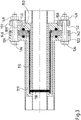
- FIG Figure 1 shows a plug-in coupling which is designated as a whole by the reference symbol 100.
- the plug-in coupling 100 includes a coupling plug 101 and a coupling socket 102, which are shown in FIG Figure 1 are shown before assembly and with a small distance from each other.
- the coupling plug 101 is connected to a first cryogenic line 103 and the coupling socket 102 is connected to a second cryogenic line 104.
- the first cryogenic line 103 has an outer tube 106 and an inner tube 107, which are separated from one another by an intermediate space 108 and thermally insulated from one another by an insulating vacuum in the intermediate space 108.
- the cryogenic lines 103, 104 are double-walled, vacuum-insulated cryogenic lines.
- the coupling plug 101 comprises a first connection flange 109, an outer pipe section 111 and an inner pipe section 112.
- the outer pipe 106 of the first cryogenic line 103 is welded to a first main surface of the first connection flange 109.
- the outer pipe section 111 is welded to the first connection flange 109.
- a distal end 113 of the outer pipe section 111 remote from the first connection flange is connected to the inner pipe section 112, which extends towards the first connection flange and is connected to the inner pipe 107 of the first cryogenic line 103.
- An annular gap 114 is formed between the outer pipe section 111 and the inner pipe section 112.
- the intermediate space 108 is fluidically connected to the annular gap 114, so that the insulating vacuum extends into the annular gap 114 and ensures good thermal insulation of the inner pipe section 112.
- An electrically insulating sleeve 116 is pushed onto the outer pipe section 111 of the plug-in coupling 101.
- the sleeve 116 is slightly longer than the outer pipe section 111 and therefore protrudes from the distal end 113 of the plug-in coupling 101 and forms a protruding edge 117 which holds an annular seal 118 which rests on the distal end 113 of the plug-in coupling 101.
- the seal 118 is made of an electrically insulating material, for example polytetrafluoroethylene (PTFE) or Torlon®.
- An annular groove 120, into which a seal 121 is inserted, is pierced in the first connection flange 109.
- the seal 121 can be designed to be electrically conductive or electrically non-conductive.
- the coupling socket 102 has a second connection flange 122, an outer pipe section 123 and an inner pipe section 124.
- the pipe sections 123, 124 are each welded with one end to the second connection flange 122, with an annular gap 126 again being formed between the pipe sections 123, 124.
- the respective other ends of the pipe sections 123, 124 are connected to the second cryogenic line 104.
- the second cryogenic line has an outer tube 128 and an inner tube 129.
- An intermediate space 130 is formed between the outer tube 128 and the inner tube 129, in which there is an insulating vacuum which thermally insulates the inner tube 129.
- the outer pipe 128 of the second cryogenic line 104 is connected to the outer pipe section 123 and the inner pipe 129 to the inner pipe section 124 of the coupling socket 102, so that the space 130 is in flow connection with the annular gap 126 and the insulating vacuum extends into the annular gap 126 of the coupling socket 102 extends into it and ensures good thermal insulation of the inner pipe section 124 of the coupling socket 102.
- the outer diameter of the insulating sleeve 116 is smaller than the inner diameter of the inner pipe section of the coupling socket, so that an annular gap 131 ( Figure 2 ) forms.
- annular seat 132 is formed for the seal 118, which rests against the seat 132 when the coupling plug 101 is fully inserted into the coupling socket 102 ( Figure 2 ).
- the first and the second connection flange 109, 122 have through holes 133, 134 for fastening screws 136.
- the through holes 134 have a diameter which is larger than the diameter of the fastening screws 136 in order to enable the installation of insulating bushings 137 which, in the assembled state, rest with a collar 138 on the second connection flange 122.
- An annular groove 139, into which a seal 141 is inserted, is pierced in the second connection flange 122.
- the seal 141 can be designed to be electrically conductive or electrically non-conductive.
- An insulating washer 142 is arranged between the first and the second connecting flange 109, 122, which has a central opening 143 through which the insulating sleeve 116 protrudes.
- the insulating washer 142 On the side facing the second connection flange 122, the insulating washer 142 has an annular projection 144 which fits exactly into an annular recess 145 in the second connecting flange 122 and is used to center the insulating washer 142.
- an annular recess 146 is provided in the insulating disk 142, which, in the assembled state of the plug-in coupling, receives a circumferential collar 147 of the insulating sleeve 116.
- the annular projections and recesses ensure that the individual components are centered with respect to one another.
- the insulating washer 142 also has through-holes 148 for the fastening screws 136, which are arranged at the same angular positions as the through-holes 133, 134 in the first and second connection flange 109, 122, in order to enable the fastening screws 136 to be installed when the insulating washer 142 and the first or Second connection flange 109, 122 are rotated into a corresponding rotational position.
- FIG 2 shows the plug-in coupling 100 Figure 1 in an assembled state.
- the fastening screws 136 are mounted with the aid of screw nuts 149 and washers 150 and press the first and second connecting flanges 109, 122 from both sides against the insulating washer 142.
- the thickness D of the insulating washer 142 is dimensioned such that the distal end 113 of the Coupling plug 101 presses the seal 118 onto the seat 132 of the coupling socket 102.
- the seal 118 seals the transition between the coupling plug 101 and the coupling socket 102. Since the seal 118 is in contact with cryogenic media when the plug-in coupling is in operation, 100 percent tightness may not be guaranteed.
- cryogenic medium penetrates past the seal 118 into the annular gap 131 between the insulating sleeve 116 and the inner tube 124 of the coupling socket 102 and evaporates there, then the seals 121,141, which are arranged in the warm area of the first or second connection flange 109,122, prevent evaporated medium escapes from the plug-in coupling into the environment.
- flammable media such as liquid natural gas or liquid hydrogen, this is extremely undesirable.
- the coupling plug When assembling the plug-in coupling, the coupling plug is first inserted into the coupling socket. The insulating washer 142 is then rotated until the through holes 148 in the insulating washer 142 are aligned with the through holes 134 in the second connection flange 122. This rotational position of the insulating disk 142 is fixed with one or more partially inserted fastening screws 136. The coupling plug 101 is then rotated until the fastening screws 136 can also be pushed through the through holes 133 in the first connection flange 109 and can be fixed with the screw nuts 149.
- the insulating disk 142 can be rotated relatively easily, but the plug-in coupling 101 often cannot because the plug-in coupling is fixed to the first cryogenic line 103 connected is.
- a further exemplary embodiment is therefore proposed in which the plug-in coupling 100 is easier to close.
- FIG. 3 shows a second embodiment of the plug connection 100 according to the invention, which differs from the plug connection according to FIG Figure 2
- the main difference is that the first connection flange 109 'with the fastening screws is not pressed directly against the insulating washer 142 or the second fastening flange 122, but rather the clamping force of the fastening screws 136 is exerted on a rotatable rotary flange 151 which is attached to the first connection flange 109' is applied and thus transmits the force exerted by the fastening screws 136 to the first connection flange 109 '.
- connection flange 109 ' is reduced to such an extent that the fastening screws 136 pass an outer circumference of the first connection flange 109'.
- the rotary flange 151 is designed as a circular ring disk which has through holes 152 for the fastening screws 136.
- the through holes 152 are arranged concentrically to the through holes 134 in the second connection flange 122.
- the rotary flange 151 is received in a seat 153 on the first connection flange 109 'with little play, so that the rotary flange 151 on the first connection flange 109' can easily be rotated into a rotary position in which the through holes 152 with the through holes 134 in the second connection flange 122 are aligned so that the fastening screws 136 can be mounted.
- the first and second connection flange to a certain extent swap their roles in the sense that a rotary flange rests on the second connection flange.
- the outer diameter of the second connection flange is smaller, so that the fastening screws 136 pass the outer circumference of the second connection flange.
- the insulating sockets 137 are arranged in the first connection flange 109.
- the insulating sleeve 116 and the insulating washer 142 are designed as a one-piece individual part, as a result of which the number of individual parts of the plug-in coupling 100 is reduced.
- the item can also have advantages when assembling the plug-in coupling.
Landscapes
- Engineering & Computer Science (AREA)
- General Engineering & Computer Science (AREA)
- Mechanical Engineering (AREA)
- Thermal Insulation (AREA)
- Filling Or Discharging Of Gas Storage Vessels (AREA)
- Flanged Joints, Insulating Joints, And Other Joints (AREA)
Abstract
Description
- Die Erfindung betrifft eine Steckkupplung für vakuumisolierte flexible Leitungen, die auch unter dem Begriff "Johnston-Kupplung" bekannt ist. Insbesondere betrifft die Erfindung eine Johnston-Kupplung mit galvanischer Trennung.
- Tiefkalte Medien, die auch als kryogene Flüssigkeiten bezeichnet werden, werden häufig auf Schiffen, in Tankwaggons oder auf Tanklastwagen transportiert. Ein wichtiges Beispiel hierfür ist flüssiges Erdgas (LNG), das eine Verdampfungstemperatur von -162 °C (111 K) hat. Die Verladung wird typischerweise mit nicht-isolierten Leitungen und Kupplungen durchgeführt, die während der Verladung vereisen. Die fehlende Wärmeisolierung führt zur Verdampfung eines Teils des tiefkalten Mediums, was mit einem Energieverlust einhergeht, denn das verdampfte Medium muss an anderer Stelle mit hohem Energieaufwand wieder verflüssigt werden.
- Bei der Verladung noch kälterer Medien, zum Beispiel flüssigem Wasserstoff (Verdampfungstemperatur -253 °C, 20 K) oder flüssigem Helium (Verdampfungstemperatur -269 °C, 4 K) würde an der Oberfläche von nicht-isolierten Leitungen und Kupplungen der Sauerstoff in der Umgebungsluft kondensieren, dessen Verdampfungstemperatur vergleichsweise höher ist (-183 °C; 90 K). Das ist höchst unerwünscht, weil durch flüssigen Sauerstoff eine potentielle Brandgefahr erheblich steigt.
- Darüber hinaus sind für den Transport von solchen kryogenen Flüssigkeiten oder Medien auch vakuumisolierte Leitungen bekannt, die beispielsweise von der Firma Nexans hergestellt werden. Für Tank- und Verladezwecke sind die vakuumisolierten Leitungen flexibel ausgebildet und an einem Ende mit einer sogenannten Johnston-Kupplung ausgerüstet, mittels der zwei kryogene Leitungen verbindbar sind, ohne dass an der Verbindungsstelle die Wärmeisolierung verloren geht. Dadurch werden eine Vereisung der Kupplungsstelle und Verluste des kryogenen Mediums durch Verdampfung verringert.
- Einfach ausgedrückt werden bei einer Johnston-Kupplung zwei doppelwandige vakuumisolierte Rohrleitungen ineinandergesteckt. Die Innendurchmesser solcher Rohrleitungen betragen typischerweise zwischen 20 mm und 150 mm. Grundsätzlich sind aber auch kleinere oder größere Innendurchmesser möglich. Das männliche Teil (innere doppelwandige Rohrleitung) wird in das weibliche Teil (äußere doppelwandige Rohrleitung) gesteckt. Man spricht auch von Kupplungsstecker und Kupplungsdose. Dadurch wird die äußere Oberfläche sehr gut zum inneren medienführenden Rohr wärmeisoliert. Hierfür müssen beide doppelwandigen Rohrleitungen über eine vorbestimmte Länge ineinandergesteckt werden. Je nach Medium und gewünschter Wärmeisolierung liegen typische Rohr-in-Rohr-Längen im Bereich von 200 mm bis 600 mm. Abweichungen zu kleineren oder größeren Längen sind bei einzelnen Anwendungsfällen möglich.
- Rohrverbindungen, die zwei Objekte miteinander verbinden, die auf unterschiedlichem elektrischem Potenzial liegen, weisen eine galvanische Trennung auf, um die beiden Objekte elektrisch voneinander zu isolieren. Beispielsweise zwischen einem Schiff und einem Hafenkai, an dem das Schiff festgemacht ist, besteht immer eine Spannungsdifferenz. Dieser Spannungsunterschied wird beispielsweise durch ein kathodisches Schutzsystem eines Schiffes oder durch galvanisch erzeugte Spannungen erzeugt.
- Der genannte Spannungsunterschied kann zum Entstehen von Zündquellen führen, die insbesondere beim Be- oder Entladen von brennbaren Produkten eine erhebliche Gefahrenquelle darstellen. Solche Zündquellen können zum Beispiel durch eine elektrische Verbindung zwischen dem Schiff und dem Hafenkai vermieden werden. In der Praxis hat es sich jedoch gezeigt, dass die in der elektrischen Verbindung fließenden Ströme zu einer unzulässigen Erwärmung der elektrischen Verbindung führen können.
- Zur Vermeidung dieser Probleme wurden Vorschriften erlassen gemäß derer Schiff und eine Einrichtung an Land bzw. auf einem Hafenkai elektrisch getrennt bleiben sollen. Für Öltankschiffe und Terminals wird beispielsweise gefordert, dass Schiff und Uferstruktur elektrisch voneinander getrennt sind. Hierfür wird ein Isolierflansch in die Transportleitungen zwischen Schiff und Land eingesetzt. Ein solcher Isolierflansch ist beispielsweise aus der
EP 0 113 948 A1 bekannt, die einen Kupplungskörper aus einem isolierenden Material vorschlägt, der beidseitig mit ringförmigen Flanschen eine Rohrleitung verbunden ist, die auf der einen Seite zu dem Schiff und auf der anderen Seite zu einer landseitigen Einrichtung führt. Die Rohrleitung ist als nicht isolierte Rohrleitung ausgebildet. - Solche nicht isolierten Rohrleitungen funktionieren gut für den Transport von Flüssigkeiten, die bei Raumtemperatur flüssig sind, aber nicht für tiefkalte Medien bzw. kryogene Flüssigkeiten, die aus den eingangs genannten Gründen vakuumisolierte Leitungen und Kupplungen erforderlich machen.
- Hiervon ausgehend hat die vorliegende Erfindung die Aufgabe, eine Steckkupplung für Kryoleitungen mit einer galvanischen Trennung zu schaffen, um eines oder mehrere der eingangs genannten Probleme zu überwinden oder zumindest zu verbessern.
- Zur Lösung dieser Aufgabe schlägt die Erfindung nach einem ersten Aspekt eine Steckkupplung zum Verbinden einer ersten mit einer zweiten doppelwandigen vakuumisolierten Kryoleitung vor. Die Steckkupplung umfasst einen Kupplungsstecker und eine Kupplungsdose. Der Kupplungsstecker weist ein inneres und ein äußeres Rohrstück sowie einen ersten Anschlussflansch auf und ist mit der ersten Kryoleitung verbunden. Die Kupplungsdose weist ein inneres und ein äußeres Rohrstück sowie einen zweiten Anschlussflansch auf und ist mit der zweiten Kryoleitung verbunden. An einem distalen Ende des Kupplungssteckers ist eine kreisringförmige Dichtung angeordnet, so dass eine abgedichtete Verbindung zwischen der Kupplungsdose und dem Kupplungsstecker entsteht, wenn der Kupplungsstecker vollständig in die Kupplungsdose eingesteckt ist. Die erfindungsgemäße Steckkupplung zeichnet sich dadurch aus,
- dass die Dichtung an dem distalen Ende des Kupplungssteckers elektrisch isolierend ausgebildet ist,
- dass eine isolierende Hülse auf dem äußeren Rohrstück des Kupplungssteckers angeordnet ist und
- dass eine Isolierscheibe zwischen dem ersten und dem zweiten Anschlussflansch liegt, wenn der Kupplungsstecker in die Kupplungsdose gesteckt ist.
- Die vorgeschlagene Steckkupplung bietet eine Lösung an, um einerseits tiefkalte Medien mittels einer vakuumisolierten Leitung zu transportieren, was im Hinblick auf Energieverluste durch Verdampfen des transportierten Mediums vorteilhaft ist. Gleichzeitig gestattet die vorgeschlagene Steckkupplung eine elektrische Trennung zwischen den Kupplungsteilen, die beispielsweise bei der Beladung von Schiffen wünschenswert bzw. zwingend vorgeschrieben ist.
- Bei einer Weiterbildung der erfindungsgemäßen Steckkupplung sind in dem ersten und dem zweiten Anschlussflansch Durchgangslöcher für Schrauben zur Verbindung des ersten mit dem zweiten Anschlussflansch vorgesehen, in welche isolierende Buchsen eingesetzt sind, welche die Schrauben gegenüber dem ersten und/oder zweiten Anschlussflansch elektrisch isolieren.
- Bei einer bevorzugten Ausführungsform der Steckkupplung ist der Außendurchmesser des ersten Anschlussflansches kleiner als der Außendurchmesser des zweiten Anschlussflansches. Auf dem ersten Anschlussflansch liegt ein drehbarer Drehflansch mit Durchgangslöchern für Schrauben auf, der in eine Drehstellung bringbar ist, in der die Durchgangslöcher des Drehflansches mit den Durchgangslöchern in dem zweiten Anschlussflansch fluchten.
- Bei diesem Ausführungsbeispiel ist es nicht notwendig den Kupplungsstecker in der Kupplungsdose zu drehen, um zu erreichen, dass Durchgangslöcher für Befestigungsschrauben in dem Kupplungsstecker bzw. in der Kupplungsdose miteinander fluchten. Die Handhabung bei dem Schließen der Steckkupplung wird dadurch erheblich vereinfacht, weil die doppelwandige vakuumisolierten Kryoleitungen ein erhebliches Gewicht aufweisen können und nicht leicht zu bewegen sind.
- Bei einer vorteilhaften Weiterbildung der Steckkupplung ist eine Dichtung zwischen der Isolierscheibe und dem zweiten Anschlussflansch und/oder zwischen der Isolierscheibe und dem ersten Anschlussflansch angeordnet. Diese zusätzliche(n) Dichtung(en) hat bzw. haben die Aufgabe, die Steckkupplung im warmen Bereich abzudichten für den Fall, dass die Dichtung an dem distalen Ende des Kupplungssteckers wegen der dort herrschenden niedrigen Temperaturen die Steckkupplung nicht einwandfrei abdichtet. Die zusätzlichen Dichtungen sorgen dafür, dass auch in dieser ungünstigen Situation kein verdampftes Medium austreten kann, das unter Umständen ein Explosionsrisiko darstellen kann.
- Bei einer Abwandlung der Steckkupplung sind die Isolierscheibe und die isolierende Hülse als einstückiges Einzelteil ausgebildet. Bei dem Zusammenbau des Kupplungssteckers sind dadurch weniger Teile zu montieren.
- Nach einem zweiten Aspekt der Erfindung wird eine Verladeeinrichtung für kryogene Fluide mit einer Steckkupplung gemäß dem ersten Aspekt der Erfindung vorgeschlagen.
- Diese Verladeeinrichtung verwirklicht die im Zusammenhang mit der Steckkupplung bereits beschriebenen Vorteile bei der Verladung von tiefkalten Medien zwischen einem Schiff und einer an Land gelegenen Einrichtung.
- Nachfolgend wird die Erfindung anhand zweier Ausführungsbeispiele unter Bezugnahme auf die begleitenden Figuren exemplarisch näher erläutert. Alle Figuren sind rein schematisch und nicht maßstäblich. Es zeigen:
- Fig. 1
- eine schematische Explosionsdarstellung einer Johnston-Kupplung mit galvanischer Trennung;
- Fig. 2
- die Johnston-Kupplung aus
Figur 1 nach dem Zusammenbau; und - Fig. 3
- ein weiteres Ausführungsbeispiel einer Johnston-Kupplung mit galvanischer Trennung im zusammengebauten Zustand.
- Gleiche oder ähnliche Elemente sind in den Figuren mit gleichen oder ähnlichen Bezugszeichen versehen.
-
Figur 1 zeigt eine Steckkupplung, die als Ganzes mit dem Bezugszeichen 100 bezeichnet ist. Zu der Steckkupplung 100 gehören ein Kupplungsstecker 101 und eine Kupplungsdose 102, die inFigur 1 vor dem Zusammenbau und mit einem kleinen Abstand voneinander dargestellt sind. - Der Kupplungsstecker 101 ist mit einer ersten Kryoleitung 103 und die Kupplungsdose 102 mit einer zweiten Kryoleitung 104 verbunden. Die erste Kryoleitung 103 weist ein Außenrohr 106 sowie ein Innenrohr 107 auf, die durch einen Zwischenraum 108 voneinander getrennt und durch ein Isoliervakuum in dem Zwischenraum 108 thermisch voneinander isoliert sind. Die Kryoleitungen 103,104 sind doppelwandige vakuumisolierte Kryoleitungen.
- Der Kupplungsstecker 101 umfasst einen ersten Anschlussflansch 109, ein äußeres Rohrstück 111 sowie ein inneres Rohrstück 112. Das Außenrohr 106 der ersten Kryoleitung 103 ist an eine erste Hauptfläche des ersten Anschlussflansches 109 angeschweißt. Auf der gegenüberliegenden Hauptfläche des Anschlussflansches 109 ist das äußere Rohrstück 111 an den ersten Anschlussflansch 109 angeschweißt. Ein von dem ersten Anschlussflansch entferntes distales Ende 113 des äußeren Rohrstückes 111 ist mit dem inneren Rohrstück 112 verbunden, das sich zu dem ersten Anschlussflansch hin erstreckt und mit dem Innenrohr 107 der ersten Kryoleitung 103 verbunden ist. Zwischen dem äußeren Rohrstück 111 und dem inneren Rohrstück 112 ist ein Ringspalt 114 ausgebildet. Der Zwischenraum 108 ist mit dem Ringspalt 114 strömungsmäßig verbunden, sodass sich das Isoliervakuum bis in den Ringspalt 114 hinein erstreckt und für eine gute thermische Isolierung des inneren Rohrstückes 112 sorgt.
- Auf das äußere Rohrstück 111 der Steckkupplung 101 ist eine elektrisch isolierende Hülse 116 aufgesteckt. Die Hülse 116 ist etwas länger als das äußere Rohrstück 111 und steht deshalb an dem distalen Ende 113 der Steckkupplung 101 über und bildet einen überstehenden Rand 117, der eine kreisringförmige Dichtung 118 haltert, die an dem distalen Ende 113 der Steckkupplung 101 anliegt. Die Dichtung 118 ist aus einem elektrisch isolierenden Material hergestellt, zum Beispiel aus Polytetrafluorethylen (PTFE) oder Torlon ®. In dem ersten Anschlussflansch 109 ist eine Ringnut 120 eingestochen, in die eine Dichtung 121 eingesetzt ist. Die Dichtung 121 kann elektrisch leitend oder elektrisch nichtleitend ausgebildet sein.
- Die Kupplungsdose 102 weist einen zweiten Anschlussflansch 122, ein äußeres Rohrstück 123 und ein Inneres Rohrstück 124 auf. Die Rohrstücke 123,124 sind jeweils mit einem Ende an dem zweiten Anschlussflansch 122 angeschweißt, wobei zwischen den Rohrstücken 123,124 wiederum ein Ringspalt 126 ausgebildet ist. Die jeweils anderen Enden der Rohrstücke 123,124 sind mit der zweiten Kryoleitung 104 verbunden. Die zweite Kryoleitung weist ein Außenrohr 128 und ein Innenrohr 129 auf. Zwischen dem Außenrohr 128 und dem Innenrohr 129 ist ein Zwischenraum 130 gebildet, in dem ein Isoliervakuum herrscht, welches das Innenrohr 129 thermisch isoliert. Das Außenrohr 128 der zweiten Kryoleitung 104 ist mit dem äußeren Rohrstück 123 und das Innenrohr 129 mit dem inneren Rohrstück 124 der Kupplungsdose 102 verbunden, sodass der Zwischenraum 130 mit dem Ringspalt 126 strömungsmäßig in Verbindung steht und sich das Isoliervakuum bis in den Ringspalt 126 der Kupplungsdose 102 hinein erstreckt und für eine gute thermische Isolierung des inneren Rohrstückes 124 der Kupplungsdose 102 sorgt. Der Außendurchmesser der isolierenden Hülse 116 ist kleiner als der Innendurchmesser des inneren Rohrstücks der Kupplungsdose, sodass sich zwischen der Hülse 116 und dem inneren Rohrstück 124 ein Ringspalt 131 (
Figur 2 ) bildet. - An dem Übergang zwischen der Kupplungsdose 102 und der zweiten Kryoleitung 104 ist ein ringförmiger Sitz 132 für die Dichtung 118 ausgebildet, die an dem Sitz 132 anliegt, wenn der Kupplungsstecker 101 vollständig in die Kupplungsdose 102 eingesteckt ist (
Figur 2 ). - In radialer Richtung außen liegend weisen der erste und der zweite Anschlussflansch 109,122 Durchgangslöcher 133,134 für Befestigungsschrauben 136 auf. Die Durchgangslöcher 134 haben einen Durchmesser, der größer als der Durchmesser der Befestigungsschrauben 136 ist, um den Einbau von isolierenden Buchsen 137 zu ermöglichen, die im montierten Zustand mit einem Kragen 138 an dem zweiten Anschlussflansch 122 anliegen. In dem zweiten Anschlussflansch 122 ist eine Ringnut 139 eingestochen, in die eine Dichtung 141 eingesetzt ist. Die Dichtung 141 kann elektrisch leitend oder elektrisch nichtleitend ausgebildet sein.
- Zwischen dem ersten und dem zweiten Anschlussflansch 109,122 ist eine Isolierscheibe 142 angeordnet, die eine zentrale Öffnung 143 aufweist, durch welche die isolierende Hülse 116 hindurchragt.
- Die Isolierscheibe 142 weist auf der dem zweite Anschlussflansch 122 zugewandten Seite einen ringförmigen Vorsprung 144 auf, der genau in eine ringförmige Ausnehmung 145 in dem zweiten Anschlussflansch 122 passt und zur Zentrierung der Isolierscheibe 142 dient. Auf ihrer gegenüberliegenden Seite ist in der Isolierscheibe 142 eine ringförmige Ausnehmung 146 vorgesehen, die im zusammengebauten Zustand der Steckkupplung einen umlaufenden Kragen 147 der isolierenden Hülse 116 aufnimmt. Die ringförmigen Vorsprünge und Ausnehmungen sorgen für eine Zentrierung der einzelnen Bauteile zueinander. Die Isolierscheibe 142 weist darüber hinaus Durchgangslöcher 148 für die Befestigungsschrauben 136 auf, die an denselben Winkelpositionen angeordnet sind wie die Durchgangslöcher 133,134 in dem ersten bzw. zweiten Anschlussflansch 109,122, um die Montage der Befestigungsschrauben 136 zu ermöglichen, wenn die Isolierscheibe 142 und der erste bzw. zweite Anschlussflansch 109,122 in eine entsprechende Drehposition gedreht sind.
-
Figur 2 zeigt die Steckkupplung 100 ausFigur 1 in einem zusammengebauten Zustand. Die Befestigungsschrauben 136 sind mithilfe von Schraubenmuttern 149 und Unterlegscheiben 150 montiert und pressen den ersten und zweiten Anschlussflansch 109,122 von beiden Seiten her gegen die Isolierscheibe 142. Die Dicke D der Isolierscheibe 142 ist dabei so bemessen, dass das distale Ende 113 des Kupplungssteckers 101 die Dichtung 118 auf den Sitz 132 der Kupplungsdose 102 drückt. Die Dichtung 118 dichtet dabei den Übergang zwischen den Kupplungsstecker 101 und der Kupplungsdose 102 ab. Da sich die Dichtung 118 im Betrieb der Steckkupplung in Kontakt mit tiefkalten Medien befindet, ist eine 100-prozentige Dichtigkeit unter Umständen nicht gewährleistet. Falls tiefkaltes Medium an der Dichtung 118 vorbei in den Ringspalt 131 zwischen der isolierenden Hülse 116 und dem Innenrohr 124 der Kupplungsdose 102 eindringt und dort verdampft, dann verhindern die Dichtungen 121,141, die im warmen Bereich des ersten bzw. zweiten Anschlussflansches 109,122 angeordnet sind, dass verdampftes Medium aus der Steckkupplung in die Umgebung austritt. Bei entzündlichen Medien wie zum Beispiel flüssigem Erdgas oder flüssigem Wasserstoff ist das in höchstem Grade unerwünscht. - Wie aus
Figur 2 ersichtlich ist existiert keine metallische Verbindung zwischen dem Kupplungsstecker 101 und der Kupplungsdose 102. Die elektrische isolierende Dichtung 118, die elektrische isolierende Hülse 116 sowie die Isolierscheibe 142 verhindern, dass sich Metallteile des Kupplungsstecker 101 und der Kupplungsdose 102 berühren. Das gilt selbst dann, wenn der Kupplungsstecker 101 schräg oder verkantet in die Kupplungsdose eingeführt wird. Die elektrische isolierende Hülse 116 verhindert, dass Metallteile des Kupplungssteckers 101 mit dem inneren Rohrstück 124 der Kupplungsdose 102 in Berührung kommen. Die Befestigungsschrauben 136 sind in den elektrisch isolierenden Hülsen 137 geführt und stellen ebenso keinen elektrischen Kontakt zwischen dem Kupplungsstecker 101 und der Kupplungsdose 102 her. Auf diese Weise wird eine galvanische Trennung zwischen den Kupplungsstecker 101 und der Kupplungsdose 102 erreicht. - Bei dem Zusammenbau der Steckkupplung wird zunächst der Kupplungsstecker in die Kupplungsdose eingesteckt. Dann wird die Isolierscheibe 142 verdreht bis die Durchgangslöcher 148 in der Isolierscheibe 142 mit den Durchgangslöchern 134 in dem zweiten Anschlussflansch 122 fluchten. Diese Drehposition der Isolierscheibe 142 wird mit einer oder mehreren teilweise eingesteckten Befestigungsschrauben 136 fixiert. Dann wird der Kupplungsstecker 101 verdreht bis die Befestigungsschrauben 136 auch durch die Durchgangslöcher 133 in dem ersten Anschlussflansch 109 durchsteckbar sind und mit den Schraubenmuttern 149 fixiert werden können.
- Die Isolierscheibe 142 lässt sich relativ leicht drehen, die Steckkupplung 101 häufig jedoch nicht, weil die Steckkupplung mit der ersten Kryoleitung 103 fest verbunden ist. Daher wird ein weiteres Ausführungsbeispiel vorgeschlagen, bei dem die Steckkupplung 100 einfacher zu schließen ist.
-
Figur 3 zeigt ein zweites Ausführungsbeispiel der erfindungsgemäßen Steckverbindung 100, die sich von der Steckverbindung gemäßFigur 2 vor allem dadurch unterscheidet, dass der erste Anschlussflansch 109' mit den Befestigungsschrauben nicht unmittelbar gegen die Isolierscheibe 142 bzw. den zweiten Befestigungsflansch 122 gedrückt wird, sondern die Spannkraft der Befestigungsschrauben 136 wird auf einen drehbaren Drehflansch 151 ausgeübt, der an dem ersten Anschlussflansch 109' anliegt und so die von den Befestigungsschrauben 136 ausgeübte Kraft auf den ersten Anschlussflansch 109' überträgt. Zu diesem Zweck ist der Außendurchmesser des Anschlussflansches 109' soweit reduziert, dass die Befestigungsschrauben 136 an einem Außenumfang des ersten Anschlussflansches 109' vorbeigehen. Der Drehflansch 151 ist als Kreisringscheibe ausgebildet, die Durchgangslöcher 152 für die Befestigungsschrauben 136 aufweist. Die Durchgangslöcher 152 sind konzentrisch zu den Durchgangslöchern 134 in dem zweiten Anschlussflansch 122 angeordnet. Der Drehflansch 151 ist in einem Sitz 153 auf dem erste Anschlussflansch 109' mit geringem Spiel aufgenommen, sodass der Drehflansch 151 auf dem ersten Anschlussflansch 109' einfach in eine Drehstellung zu drehen ist, in der die Durchgangslöcher 152 mit den Durchgangslöchern 134 in dem zweiten Anschlussflansch 122 fluchten, so dass die Befestigungsschrauben 136 montierbar sind. Bei diesem Ausführungsbeispiel ist es nicht erforderlich den Kupplungsstecker 101 nach dem Einstecken in die Kupplungsdose 102 zu verdrehen. Es genügt den Drehflansch 151 zu drehen, was für das Personal, dass die Steckkupplungsverbindung herstellt eine erhebliche Erleichterung ist. - Bei einer in den Figuren nicht dargestellten Abwandlung des zweiten Ausführungsbeispiels tauschen der erste und der zweite Anschlussflansch gewissermaßen in den Sinn ihre Rollen, dass ein Drehflansch auf dem zweiten Anschlussflansch aufliegt. Bei diesem abgewandelten zweiten Ausführungsbeispiel ist der Außendurchmesser des zweiten Anschlussflansches kleiner, sodass die Befestigungsschrauben 136 am Außenumfang des zweiten Anschlussflansches vorbeigehen. Auf diese Weise wird wieder erreicht, dass bei der Montage der Steckkupplung nur der leicht drehbare Drehflansch in eine Drehstellung gebracht werden muss, damit die Durchgangslöcher in dem Drehflansch mit den Durchgangslöchern in dem ersten Anschlussflansch fluchten und die Befestigungsschrauben montiert werden können. Bei dieser abgewandelten Ausführungsform sind die isolierenden Buchsen 137 in dem ersten Anschlussflansch 109 angeordnet.
- In einer weiteren Abwandlung des ersten bzw. zweiten Ausführungsbeispiels sind die isolierende Hülse 116 und die Isolierscheibe 142 als einstückiges Einzelteil ausgebildet, wodurch die Anzahl der Einzelteile der Steckkupplung 100 reduziert wird. Das Einzelteil kann auch Vorteile bei der Montage der Steckkupplung haben.
Bezugszeichenliste 100 Steckkupplung 133 Durchgangsloch 101 Kupplungsstecker 134 Durchgangsloch 102 Kupplungsdose 103 erste Kryoleitung 136 Befestigungsschraube 104 zweite Kryoleitung 137 Isolierende Buchsen 138 Kragen an der isolierenden Buchse 106 Außen rohr 139 Ringnut 107 Innenrohr 108 Zwischenraum 141 Dichtung 109,109' erste Anschlussflansch 142 Isolierscheibe 143 Zentrale Öffnung 111 Äußeres Rohrstück 144 Ringförmiger Vorsprung 112 Inneres Rohrstück 145 Ringförmige Ausnehmung 113 Distales Ende 146 Ringförmige Ausnehmung 114 Ringspalt 147 Umlaufender Kragen 148 Durchgangsloch 116 Isolierende Hülse 149 Schraubenmutter 117 Überstehender Rand 150 Unterlegscheibe 118 Dichtung 151 Drehflansch 152 Durchgangslöcher 120 Ringnut 153 Sitz 121 Dichtung 122 zweite Anschlussflansch 123 Äußeres Rohrstück 124 Inneres Rohrstück 126 Ringspalt 128 Außenrohr 129 Innenrohr 131 Zwischenraum 132 ringförmiger Sitz
Claims (6)
- Steckkupplung zum Verbinden einer ersten mit einer zweiten doppelwandigen vakuumisolierten Kryoleitung (103,104), wobei die Steckkupplung (100) einen Kupplungsstecker (101) und eine Kupplungsdose (102) umfasst,- wobei der Kupplungsstecker (101) ein inneres und ein äußeres Rohrstück (111,112) sowie einen ersten Anschlussflansch (109,109') aufweist und mit der ersten Kryoleitung (103) verbunden ist,- wobei die Kupplungsdose (102) ein inneres und ein äußeres Rohrstück (123,124) sowie einen zweiten Anschlussflansch (122) aufweist und mit der zweiten Kryoleitung (104) verbunden ist- wobei an einem distalen Ende (113) des Kupplungssteckers (101) eine kreisringförmige Dichtung (118) angeordnet ist, so dass eine abgedichtete Verbindung zwischen der Kupplungsdose und dem Kupplungsstecker, wenn der Kupplungsstecker vollständig in die Kupplungsdose eingesteckt ist,dadurch gekennzeichnet, dass
die Dichtung (118) an dem distalen Ende (113) des Kupplungssteckers elektrisch isolierend ausgebildet ist,
dass eine isolierende Hülse (116) auf dem äußeren Rohrstück (111) des Kupplungssteckers (101) angeordnet ist und
dass eine Isolierscheibe (142) zwischen dem ersten und dem zweiten Anschlussflansch (109,109';122) liegt, wenn der Kupplungsstecker in die Kupplungsdose gesteckt ist. - Steckkupplung nach Anspruch 1, dadurch gekennzeichnet, dass in dem ersten und dem zweiten Anschlussflansch Durchgangslöcher (133,134) für Schrauben (136) zur Verbindung des ersten mit dem zweiten Anschlussflansch (109,109';122) vorgesehen sind und in den Durchgangslöchern (133,134) isolierende Buchsen eingesetzt sind, welche die Schrauben (133,134) gegenüber dem ersten und/oder zweiten Anschlussflansch (109,109';122) elektrisch isolieren.
- Steckkupplung nach Anspruch 1 oder 2, dadurch gekennzeichnet, dass der Außendurchmesser des ersten Anschlussflansches (109,109') kleiner ist als der Außendurchmesser des zweiten Anschlussflansches (122), dass auf den ersten Anschlussflansch (109,109') ein drehbarer Drehflansch (151) mit Durchgangslöchern (152) für Schrauben (136) aufliegt, der in eine Drehstellung bringbar ist, in der die Durchgangslöcher (152) des Drehflansches (151) mit den Durchgangslöchern (134) in dem zweiten Anschlussflansch (122) fluchten.
- Steckkupplung nach einem der vorstehenden Ansprüche, dadurch gekennzeichnet, dass eine Dichtung (121) zwischen der Isolierscheibe (142) und dem ersten Anschlussflansch (109,109') und/oder zwischen der Isolierscheibe (142) und dem zweiten Anschlussflansch (122) angeordnet ist.
- Steckkupplung nach einem der vorstehenden Ansprüche, dadurch gekennzeichnet, dass die Isolierscheibe (142) und die isolierende Hülse (116) als einstückiges Einzelteil ausgebildet sind.
- Verladeeinrichtung für kryogene Fluide mit einer Steckkupplung (100) nach einem der Ansprüche 1 bis 5.
Priority Applications (3)
| Application Number | Priority Date | Filing Date | Title |
|---|---|---|---|
| EP20305042.2A EP3851724B1 (de) | 2020-01-20 | 2020-01-20 | Johnston-kupplung mit galvanischer trennung |
| US17/149,260 US11598467B2 (en) | 2020-01-20 | 2021-01-14 | Johnston coupling with galvanic separation |
| JP2021006004A JP7822697B2 (ja) | 2020-01-20 | 2021-01-18 | ガルバニック絶縁を有するジョンストンカプリング |
Applications Claiming Priority (1)
| Application Number | Priority Date | Filing Date | Title |
|---|---|---|---|
| EP20305042.2A EP3851724B1 (de) | 2020-01-20 | 2020-01-20 | Johnston-kupplung mit galvanischer trennung |
Publications (2)
| Publication Number | Publication Date |
|---|---|
| EP3851724A1 true EP3851724A1 (de) | 2021-07-21 |
| EP3851724B1 EP3851724B1 (de) | 2022-08-10 |
Family
ID=69423260
Family Applications (1)
| Application Number | Title | Priority Date | Filing Date |
|---|---|---|---|
| EP20305042.2A Active EP3851724B1 (de) | 2020-01-20 | 2020-01-20 | Johnston-kupplung mit galvanischer trennung |
Country Status (3)
| Country | Link |
|---|---|
| US (1) | US11598467B2 (de) |
| EP (1) | EP3851724B1 (de) |
| JP (1) | JP7822697B2 (de) |
Cited By (1)
| Publication number | Priority date | Publication date | Assignee | Title |
|---|---|---|---|---|
| DE102024101039A1 (de) * | 2024-01-15 | 2025-07-17 | Viessmann Holding International GmbH | Rohrmuffe |
Families Citing this family (2)
| Publication number | Priority date | Publication date | Assignee | Title |
|---|---|---|---|---|
| NL2024894B1 (en) * | 2020-02-13 | 2021-09-15 | Ddc Eng B V | Hose |
| US12449080B2 (en) * | 2022-05-18 | 2025-10-21 | Flexsteel Usa, Llc | Pipe-in-pipe outer pipeline sealing systems and methods |
Citations (5)
| Publication number | Priority date | Publication date | Assignee | Title |
|---|---|---|---|---|
| EP0113948A1 (de) | 1983-01-12 | 1984-07-25 | Powell Duffryn Terminals Limited | Rohrverbindung |
| US5139288A (en) * | 1990-08-30 | 1992-08-18 | Texas Instruments Incorporated | Coupling device for providing electrical and thermal insulation under high pressure, cryogenic conditions |
| CN103307380A (zh) * | 2013-05-15 | 2013-09-18 | 中国科学院等离子体物理研究所 | 一种具备电位隔离功能的低温流体输送管接头 |
| CN103322357A (zh) * | 2013-05-15 | 2013-09-25 | 中国科学院等离子体物理研究所 | 一种具备电位隔离功能的复合型液氮液氦输送管接头 |
| EP3339713A1 (de) * | 2016-12-23 | 2018-06-27 | Nexans | Steckkupplung fur kryoleitungen |
Family Cites Families (15)
| Publication number | Priority date | Publication date | Assignee | Title |
|---|---|---|---|---|
| US2785536A (en) * | 1953-11-03 | 1957-03-19 | Little Inc A | Delivery tube for liquefied gases |
| US2980448A (en) * | 1958-03-24 | 1961-04-18 | Beech Aircraft Corp | Connector for joining pipelines having outer jacket insulation in continuously insulated relation |
| US3137143A (en) * | 1962-04-23 | 1964-06-16 | Robert B Jacobs | Condensing vacuum insulation |
| US3204989A (en) * | 1962-06-05 | 1965-09-07 | Barlow Corp | Pipe joint |
| US3207533A (en) * | 1963-01-17 | 1965-09-21 | Donald A Van Gundy | Double bayonet insulated transfer line coupling |
| US4011732A (en) * | 1974-02-14 | 1977-03-15 | Helix Technology Incorporated | Heat-stationed bayonet connector for cryogenic fluid lines |
| US4014369A (en) * | 1975-12-31 | 1977-03-29 | Exxon Research And Engineering Company | Triple pipe low temperature pipeline |
| JPS536923U (de) * | 1976-07-03 | 1978-01-21 | ||
| US5184850A (en) * | 1989-07-07 | 1993-02-09 | Georg Fischer Ag | Method of connecting pipes of plastics material of a double pipe system and a pipe connection made by the method |
| JPH0960774A (ja) * | 1995-08-25 | 1997-03-04 | Nagase Chuko Kk | フランジ形管継手 |
| JP4210123B2 (ja) * | 2003-01-08 | 2009-01-14 | マルヤス工業株式会社 | 流体配管接続用フランジ継ぎ手 |
| DE102005059089A1 (de) * | 2005-12-10 | 2007-06-14 | Nexans | Steckkupplung für Kryoleitungen |
| CN202580387U (zh) * | 2012-05-15 | 2012-12-05 | 青岛瑞丰气体有限公司 | 一种真空管连接法兰 |
| JP2016070376A (ja) * | 2014-09-30 | 2016-05-09 | 川崎重工業株式会社 | 低温流体用真空断熱二重管のバイヨネット継手用ガイド機構 |
| JP6585560B2 (ja) * | 2016-08-03 | 2019-10-02 | 大陽日酸株式会社 | バイオネット継手 |
-
2020
- 2020-01-20 EP EP20305042.2A patent/EP3851724B1/de active Active
-
2021
- 2021-01-14 US US17/149,260 patent/US11598467B2/en active Active
- 2021-01-18 JP JP2021006004A patent/JP7822697B2/ja active Active
Patent Citations (5)
| Publication number | Priority date | Publication date | Assignee | Title |
|---|---|---|---|---|
| EP0113948A1 (de) | 1983-01-12 | 1984-07-25 | Powell Duffryn Terminals Limited | Rohrverbindung |
| US5139288A (en) * | 1990-08-30 | 1992-08-18 | Texas Instruments Incorporated | Coupling device for providing electrical and thermal insulation under high pressure, cryogenic conditions |
| CN103307380A (zh) * | 2013-05-15 | 2013-09-18 | 中国科学院等离子体物理研究所 | 一种具备电位隔离功能的低温流体输送管接头 |
| CN103322357A (zh) * | 2013-05-15 | 2013-09-25 | 中国科学院等离子体物理研究所 | 一种具备电位隔离功能的复合型液氮液氦输送管接头 |
| EP3339713A1 (de) * | 2016-12-23 | 2018-06-27 | Nexans | Steckkupplung fur kryoleitungen |
Cited By (1)
| Publication number | Priority date | Publication date | Assignee | Title |
|---|---|---|---|---|
| DE102024101039A1 (de) * | 2024-01-15 | 2025-07-17 | Viessmann Holding International GmbH | Rohrmuffe |
Also Published As
| Publication number | Publication date |
|---|---|
| US11598467B2 (en) | 2023-03-07 |
| JP2021113615A (ja) | 2021-08-05 |
| JP7822697B2 (ja) | 2026-03-03 |
| EP3851724B1 (de) | 2022-08-10 |
| US20210254771A1 (en) | 2021-08-19 |
Similar Documents
| Publication | Publication Date | Title |
|---|---|---|
| EP3851726B1 (de) | Johnston-kupplung mit zusätzlicher vakuumhülle | |
| EP3842681B1 (de) | Schnell trennende johnston steckkupplung | |
| EP3851724B1 (de) | Johnston-kupplung mit galvanischer trennung | |
| EP2828566B1 (de) | Kupplung zum anschluss fluidführender leitungen | |
| DE69000707T2 (de) | Rohrverbindung mit einer vorrichtung zur ableitung von lecken. | |
| EP3638939A1 (de) | Kupplung für tiefkalte verflüssigte medien | |
| EP1957851B1 (de) | Steckkupplung für kryoleitungen | |
| EP2781818B1 (de) | Kupplung für tiefkalte verflüssigte Medien | |
| EP0889273B1 (de) | Kupplung zum Verbinden vakuumisolierter Leitungsenden | |
| EP3670998B1 (de) | Kupplung für fluidführende leitungen | |
| DE2857863C2 (de) | Temperatursteuereinrichtung für die Abdichtung eines Rohrdrehgelenkes | |
| EP3480826A1 (de) | Ventilblock für ein molchbares und/oder festkörperführendes leitungssystem und verteilerleitungssystem | |
| DE4339676A1 (de) | Kupplung für tiefkalte verflüssigte Medien | |
| DE3142702A1 (de) | "anordnung zum verbinden von zwei leitungsrohren bzw. zum anschluss eines leitungsrohres an eine armatur, einen behaelter etc." | |
| EP2151618B1 (de) | Vorrichtung zur Isolierung eines Rohrleitungssystems | |
| DE2218877A1 (de) | Tieftemperatur-schnellkupplung | |
| DE2212656C3 (de) | Schnellkupplung für eine kombinierte Luft- und Sprechverbindung zu einem Gasschutzanzug | |
| EP3670999A1 (de) | Johnston-kupplung mit verschiebeeinheit | |
| DE102023108303A1 (de) | Flüssigkeitsladendes Verbindungsstück für eine drehbare Verbindung von Flüssigkeitsleitungsrohren für cryogene Flüssigkeiten | |
| WO2005121626A1 (de) | Drehdurchführung mit einer gasrückführung | |
| EP0313717A1 (de) | Absperrhahn für eine Rohrleitung | |
| DE7930690U1 (de) | Absperrhahn | |
| DE102006002936A1 (de) | Armatur zum Absperren oder Regeln eines Mediums | |
| DE19621493A1 (de) | Feuersicherer Kugelhahn | |
| DE102022104635A1 (de) | Einleiten eines Fluids in einen Anschluss |
Legal Events
| Date | Code | Title | Description |
|---|---|---|---|
| PUAI | Public reference made under article 153(3) epc to a published international application that has entered the european phase |
Free format text: ORIGINAL CODE: 0009012 |
|
| STAA | Information on the status of an ep patent application or granted ep patent |
Free format text: STATUS: THE APPLICATION HAS BEEN PUBLISHED |
|
| AK | Designated contracting states |
Kind code of ref document: A1 Designated state(s): AL AT BE BG CH CY CZ DE DK EE ES FI FR GB GR HR HU IE IS IT LI LT LU LV MC MK MT NL NO PL PT RO RS SE SI SK SM TR |
|
| STAA | Information on the status of an ep patent application or granted ep patent |
Free format text: STATUS: REQUEST FOR EXAMINATION WAS MADE |
|
| 17P | Request for examination filed |
Effective date: 20220121 |
|
| RBV | Designated contracting states (corrected) |
Designated state(s): AL AT BE BG CH CY CZ DE DK EE ES FI FR GB GR HR HU IE IS IT LI LT LU LV MC MK MT NL NO PL PT RO RS SE SI SK SM TR |
|
| GRAP | Despatch of communication of intention to grant a patent |
Free format text: ORIGINAL CODE: EPIDOSNIGR1 |
|
| STAA | Information on the status of an ep patent application or granted ep patent |
Free format text: STATUS: GRANT OF PATENT IS INTENDED |
|
| INTG | Intention to grant announced |
Effective date: 20220412 |
|
| GRAS | Grant fee paid |
Free format text: ORIGINAL CODE: EPIDOSNIGR3 |
|
| GRAA | (expected) grant |
Free format text: ORIGINAL CODE: 0009210 |
|
| STAA | Information on the status of an ep patent application or granted ep patent |
Free format text: STATUS: THE PATENT HAS BEEN GRANTED |
|
| AK | Designated contracting states |
Kind code of ref document: B1 Designated state(s): AL AT BE BG CH CY CZ DE DK EE ES FI FR GB GR HR HU IE IS IT LI LT LU LV MC MK MT NL NO PL PT RO RS SE SI SK SM TR |
|
| REG | Reference to a national code |
Ref country code: AT Ref legal event code: REF Ref document number: 1510784 Country of ref document: AT Kind code of ref document: T Effective date: 20220815 Ref country code: CH Ref legal event code: EP |
|
| REG | Reference to a national code |
Ref country code: IE Ref legal event code: FG4D Free format text: LANGUAGE OF EP DOCUMENT: GERMAN |
|
| REG | Reference to a national code |
Ref country code: DE Ref legal event code: R096 Ref document number: 502020001512 Country of ref document: DE |
|
| REG | Reference to a national code |
Ref country code: NO Ref legal event code: T2 Effective date: 20220810 |
|
| REG | Reference to a national code |
Ref country code: NL Ref legal event code: MP Effective date: 20220810 |
|
| REG | Reference to a national code |
Ref country code: LT Ref legal event code: MG9D |
|
| PG25 | Lapsed in a contracting state [announced via postgrant information from national office to epo] |
Ref country code: SE Free format text: LAPSE BECAUSE OF FAILURE TO SUBMIT A TRANSLATION OF THE DESCRIPTION OR TO PAY THE FEE WITHIN THE PRESCRIBED TIME-LIMIT Effective date: 20220810 Ref country code: RS Free format text: LAPSE BECAUSE OF FAILURE TO SUBMIT A TRANSLATION OF THE DESCRIPTION OR TO PAY THE FEE WITHIN THE PRESCRIBED TIME-LIMIT Effective date: 20220810 Ref country code: PT Free format text: LAPSE BECAUSE OF FAILURE TO SUBMIT A TRANSLATION OF THE DESCRIPTION OR TO PAY THE FEE WITHIN THE PRESCRIBED TIME-LIMIT Effective date: 20221212 Ref country code: NL Free format text: LAPSE BECAUSE OF FAILURE TO SUBMIT A TRANSLATION OF THE DESCRIPTION OR TO PAY THE FEE WITHIN THE PRESCRIBED TIME-LIMIT Effective date: 20220810 Ref country code: LV Free format text: LAPSE BECAUSE OF FAILURE TO SUBMIT A TRANSLATION OF THE DESCRIPTION OR TO PAY THE FEE WITHIN THE PRESCRIBED TIME-LIMIT Effective date: 20220810 Ref country code: LT Free format text: LAPSE BECAUSE OF FAILURE TO SUBMIT A TRANSLATION OF THE DESCRIPTION OR TO PAY THE FEE WITHIN THE PRESCRIBED TIME-LIMIT Effective date: 20220810 Ref country code: FI Free format text: LAPSE BECAUSE OF FAILURE TO SUBMIT A TRANSLATION OF THE DESCRIPTION OR TO PAY THE FEE WITHIN THE PRESCRIBED TIME-LIMIT Effective date: 20220810 |
|
| PG25 | Lapsed in a contracting state [announced via postgrant information from national office to epo] |
Ref country code: PL Free format text: LAPSE BECAUSE OF FAILURE TO SUBMIT A TRANSLATION OF THE DESCRIPTION OR TO PAY THE FEE WITHIN THE PRESCRIBED TIME-LIMIT Effective date: 20220810 Ref country code: IS Free format text: LAPSE BECAUSE OF FAILURE TO SUBMIT A TRANSLATION OF THE DESCRIPTION OR TO PAY THE FEE WITHIN THE PRESCRIBED TIME-LIMIT Effective date: 20221210 Ref country code: HR Free format text: LAPSE BECAUSE OF FAILURE TO SUBMIT A TRANSLATION OF THE DESCRIPTION OR TO PAY THE FEE WITHIN THE PRESCRIBED TIME-LIMIT Effective date: 20220810 Ref country code: GR Free format text: LAPSE BECAUSE OF FAILURE TO SUBMIT A TRANSLATION OF THE DESCRIPTION OR TO PAY THE FEE WITHIN THE PRESCRIBED TIME-LIMIT Effective date: 20221111 |
|
| PG25 | Lapsed in a contracting state [announced via postgrant information from national office to epo] |
Ref country code: SM Free format text: LAPSE BECAUSE OF FAILURE TO SUBMIT A TRANSLATION OF THE DESCRIPTION OR TO PAY THE FEE WITHIN THE PRESCRIBED TIME-LIMIT Effective date: 20220810 Ref country code: RO Free format text: LAPSE BECAUSE OF FAILURE TO SUBMIT A TRANSLATION OF THE DESCRIPTION OR TO PAY THE FEE WITHIN THE PRESCRIBED TIME-LIMIT Effective date: 20220810 Ref country code: ES Free format text: LAPSE BECAUSE OF FAILURE TO SUBMIT A TRANSLATION OF THE DESCRIPTION OR TO PAY THE FEE WITHIN THE PRESCRIBED TIME-LIMIT Effective date: 20220810 Ref country code: DK Free format text: LAPSE BECAUSE OF FAILURE TO SUBMIT A TRANSLATION OF THE DESCRIPTION OR TO PAY THE FEE WITHIN THE PRESCRIBED TIME-LIMIT Effective date: 20220810 Ref country code: CZ Free format text: LAPSE BECAUSE OF FAILURE TO SUBMIT A TRANSLATION OF THE DESCRIPTION OR TO PAY THE FEE WITHIN THE PRESCRIBED TIME-LIMIT Effective date: 20220810 |
|
| REG | Reference to a national code |
Ref country code: DE Ref legal event code: R097 Ref document number: 502020001512 Country of ref document: DE |
|
| PG25 | Lapsed in a contracting state [announced via postgrant information from national office to epo] |
Ref country code: SK Free format text: LAPSE BECAUSE OF FAILURE TO SUBMIT A TRANSLATION OF THE DESCRIPTION OR TO PAY THE FEE WITHIN THE PRESCRIBED TIME-LIMIT Effective date: 20220810 Ref country code: EE Free format text: LAPSE BECAUSE OF FAILURE TO SUBMIT A TRANSLATION OF THE DESCRIPTION OR TO PAY THE FEE WITHIN THE PRESCRIBED TIME-LIMIT Effective date: 20220810 |
|
| PLBE | No opposition filed within time limit |
Free format text: ORIGINAL CODE: 0009261 |
|
| STAA | Information on the status of an ep patent application or granted ep patent |
Free format text: STATUS: NO OPPOSITION FILED WITHIN TIME LIMIT |
|
| PG25 | Lapsed in a contracting state [announced via postgrant information from national office to epo] |
Ref country code: AL Free format text: LAPSE BECAUSE OF FAILURE TO SUBMIT A TRANSLATION OF THE DESCRIPTION OR TO PAY THE FEE WITHIN THE PRESCRIBED TIME-LIMIT Effective date: 20220810 |
|
| 26N | No opposition filed |
Effective date: 20230511 |
|
| PG25 | Lapsed in a contracting state [announced via postgrant information from national office to epo] |
Ref country code: SI Free format text: LAPSE BECAUSE OF FAILURE TO SUBMIT A TRANSLATION OF THE DESCRIPTION OR TO PAY THE FEE WITHIN THE PRESCRIBED TIME-LIMIT Effective date: 20220810 |
|
| REG | Reference to a national code |
Ref country code: CH Ref legal event code: PL |
|
| PG25 | Lapsed in a contracting state [announced via postgrant information from national office to epo] |
Ref country code: LU Free format text: LAPSE BECAUSE OF NON-PAYMENT OF DUE FEES Effective date: 20230120 |
|
| REG | Reference to a national code |
Ref country code: BE Ref legal event code: MM Effective date: 20230131 |
|
| PG25 | Lapsed in a contracting state [announced via postgrant information from national office to epo] |
Ref country code: LI Free format text: LAPSE BECAUSE OF NON-PAYMENT OF DUE FEES Effective date: 20230131 Ref country code: CH Free format text: LAPSE BECAUSE OF NON-PAYMENT OF DUE FEES Effective date: 20230131 |
|
| PG25 | Lapsed in a contracting state [announced via postgrant information from national office to epo] |
Ref country code: BE Free format text: LAPSE BECAUSE OF NON-PAYMENT OF DUE FEES Effective date: 20230131 |
|
| PG25 | Lapsed in a contracting state [announced via postgrant information from national office to epo] |
Ref country code: IE Free format text: LAPSE BECAUSE OF NON-PAYMENT OF DUE FEES Effective date: 20230120 |
|
| PGFP | Annual fee paid to national office [announced via postgrant information from national office to epo] |
Ref country code: NO Payment date: 20240123 Year of fee payment: 5 |
|
| PG25 | Lapsed in a contracting state [announced via postgrant information from national office to epo] |
Ref country code: MC Free format text: LAPSE BECAUSE OF FAILURE TO SUBMIT A TRANSLATION OF THE DESCRIPTION OR TO PAY THE FEE WITHIN THE PRESCRIBED TIME-LIMIT Effective date: 20220810 |
|
| PG25 | Lapsed in a contracting state [announced via postgrant information from national office to epo] |
Ref country code: MC Free format text: LAPSE BECAUSE OF FAILURE TO SUBMIT A TRANSLATION OF THE DESCRIPTION OR TO PAY THE FEE WITHIN THE PRESCRIBED TIME-LIMIT Effective date: 20220810 |
|
| PG25 | Lapsed in a contracting state [announced via postgrant information from national office to epo] |
Ref country code: BG Free format text: LAPSE BECAUSE OF FAILURE TO SUBMIT A TRANSLATION OF THE DESCRIPTION OR TO PAY THE FEE WITHIN THE PRESCRIBED TIME-LIMIT Effective date: 20220810 |
|
| PG25 | Lapsed in a contracting state [announced via postgrant information from national office to epo] |
Ref country code: BG Free format text: LAPSE BECAUSE OF FAILURE TO SUBMIT A TRANSLATION OF THE DESCRIPTION OR TO PAY THE FEE WITHIN THE PRESCRIBED TIME-LIMIT Effective date: 20220810 |
|
| PGFP | Annual fee paid to national office [announced via postgrant information from national office to epo] |
Ref country code: AT Payment date: 20250417 Year of fee payment: 5 |
|
| PG25 | Lapsed in a contracting state [announced via postgrant information from national office to epo] |
Ref country code: CY Free format text: LAPSE BECAUSE OF FAILURE TO SUBMIT A TRANSLATION OF THE DESCRIPTION OR TO PAY THE FEE WITHIN THE PRESCRIBED TIME-LIMIT; INVALID AB INITIO Effective date: 20200120 |
|
| PG25 | Lapsed in a contracting state [announced via postgrant information from national office to epo] |
Ref country code: HU Free format text: LAPSE BECAUSE OF FAILURE TO SUBMIT A TRANSLATION OF THE DESCRIPTION OR TO PAY THE FEE WITHIN THE PRESCRIBED TIME-LIMIT; INVALID AB INITIO Effective date: 20200120 |
|
| PG25 | Lapsed in a contracting state [announced via postgrant information from national office to epo] |
Ref country code: NO Free format text: LAPSE BECAUSE OF NON-PAYMENT OF DUE FEES Effective date: 20250131 |
|
| PG25 | Lapsed in a contracting state [announced via postgrant information from national office to epo] |
Ref country code: TR Free format text: LAPSE BECAUSE OF FAILURE TO SUBMIT A TRANSLATION OF THE DESCRIPTION OR TO PAY THE FEE WITHIN THE PRESCRIBED TIME-LIMIT Effective date: 20220810 |
|
| REG | Reference to a national code |
Ref country code: AT Ref legal event code: MM01 Ref document number: 1510784 Country of ref document: AT Kind code of ref document: T Effective date: 20250120 |
|
| PGFP | Annual fee paid to national office [announced via postgrant information from national office to epo] |
Ref country code: GB Payment date: 20260123 Year of fee payment: 7 |
|
| PGFP | Annual fee paid to national office [announced via postgrant information from national office to epo] |
Ref country code: DE Payment date: 20260121 Year of fee payment: 7 |
|
| PG25 | Lapsed in a contracting state [announced via postgrant information from national office to epo] |
Ref country code: AT Free format text: LAPSE BECAUSE OF NON-PAYMENT OF DUE FEES Effective date: 20250120 |
|
| PGFP | Annual fee paid to national office [announced via postgrant information from national office to epo] |
Ref country code: IT Payment date: 20260126 Year of fee payment: 7 |
|
| PGFP | Annual fee paid to national office [announced via postgrant information from national office to epo] |
Ref country code: FR Payment date: 20260123 Year of fee payment: 7 |