EP0113948A1 - Pipe coupling - Google Patents
Pipe coupling Download PDFInfo
- Publication number
- EP0113948A1 EP0113948A1 EP83304323A EP83304323A EP0113948A1 EP 0113948 A1 EP0113948 A1 EP 0113948A1 EP 83304323 A EP83304323 A EP 83304323A EP 83304323 A EP83304323 A EP 83304323A EP 0113948 A1 EP0113948 A1 EP 0113948A1
- Authority
- EP
- European Patent Office
- Prior art keywords
- cut
- pipe coupling
- aways
- coupling according
- face
- Prior art date
- Legal status (The legal status is an assumption and is not a legal conclusion. Google has not performed a legal analysis and makes no representation as to the accuracy of the status listed.)
- Granted
Links
- 230000008878 coupling Effects 0.000 title claims abstract description 29
- 238000010168 coupling process Methods 0.000 title claims abstract description 29
- 238000005859 coupling reaction Methods 0.000 title claims abstract description 29
- 230000015572 biosynthetic process Effects 0.000 claims abstract description 11
- 238000005755 formation reaction Methods 0.000 claims abstract description 11
- 230000013011 mating Effects 0.000 claims description 4
- 230000002093 peripheral effect Effects 0.000 claims description 2
- 238000007789 sealing Methods 0.000 claims description 2
- 239000004810 polytetrafluoroethylene Substances 0.000 abstract description 2
- 229920001343 polytetrafluoroethylene Polymers 0.000 abstract description 2
- 239000000463 material Substances 0.000 description 5
- 238000006073 displacement reaction Methods 0.000 description 2
- 239000002184 metal Substances 0.000 description 2
- 229920006074 Nylatron® Polymers 0.000 description 1
- 238000004210 cathodic protection Methods 0.000 description 1
- 239000011248 coating agent Substances 0.000 description 1
- 238000000576 coating method Methods 0.000 description 1
- 238000010276 construction Methods 0.000 description 1
- 238000010438 heat treatment Methods 0.000 description 1
- 239000011810 insulating material Substances 0.000 description 1
- 238000009413 insulation Methods 0.000 description 1
- 238000003754 machining Methods 0.000 description 1
- 238000004519 manufacturing process Methods 0.000 description 1
- 239000004033 plastic Substances 0.000 description 1
- 229920003023 plastic Polymers 0.000 description 1
Images
Classifications
-
- F—MECHANICAL ENGINEERING; LIGHTING; HEATING; WEAPONS; BLASTING
- F16—ENGINEERING ELEMENTS AND UNITS; GENERAL MEASURES FOR PRODUCING AND MAINTAINING EFFECTIVE FUNCTIONING OF MACHINES OR INSTALLATIONS; THERMAL INSULATION IN GENERAL
- F16L—PIPES; JOINTS OR FITTINGS FOR PIPES; SUPPORTS FOR PIPES, CABLES OR PROTECTIVE TUBING; MEANS FOR THERMAL INSULATION IN GENERAL
- F16L25/00—Construction or details of pipe joints not provided for in, or of interest apart from, groups F16L13/00 - F16L23/00
- F16L25/02—Construction or details of pipe joints not provided for in, or of interest apart from, groups F16L13/00 - F16L23/00 specially adapted for electrically insulating the two pipe ends of the joint from each other
- F16L25/026—Construction or details of pipe joints not provided for in, or of interest apart from, groups F16L13/00 - F16L23/00 specially adapted for electrically insulating the two pipe ends of the joint from each other for flanged joints
Definitions
- the present invention relates to a pipe coupling and more particularly to a insulating pipe coupling for interconnecting ship to shore, and similar, pipework.
- an insulating coupling Because of the hard use to which such an insulating flange or pipe coupling may be put, it is preferable that its insulating properties derive from the material from which it is made, rather than from any insulating coating.
- One proposed construction of an insulating coupling consisted of a cylindrical body of insulating material having radially outwardly directed annular flanges at each end, the two flanges having through holes for bolting the flanges to mating flanges on the ship and shore pipework.
- a third radially outwardly directed flange was provided intermediate the ends of the cylinder so as to occupy the space between corresponding securing bolts of the two end flanges and prevent metal items from bridging the two.
- this pipe coupling was difficult to make with adequate strength because of the amount of material which had to be removed in its manufacture.
- a pipe coupling comprising a body having a through bore and, at respective ends, annular end faces for mating with the flanged ends of two conduits which are to be coupled, each end of the body being provided with a circumferential array of castellated formations formed by cut-aways at the junction between the respective end face and periphery of the body, each cut-away having an end wall offset axially inwardly from the adjacent end face, with the castellated formations at opposite ends angularly offset so that each castellated formation at one end is aligned with a respective one of the cut-away of the other end, with a through-hole extending between the two ends to receive the shank of a bolt.
- the body Preferably there is an un-cut-away axial central portion of the body so that the end walls of the cut-aways at the two ends are offset axially of the body relative to one another. This should assist in maintaining the strength of the pipe coupling and additionally make it even more difficult for conductive bridges to occur between the bolts secured to the respective pipework flanges.
- the body of the pipe coupling is made from an electrically insulating, or substantially electrically insulating (i.e. greater than a few ohms end to end resistance) material and any additional parts which may constitute the pipe coupling are made of such a material and are so arranged so that there is no possibility of their causing a short circuit between the flanges to which the coupling is connected.
- an electrically insulating, or substantially electrically insulating (i.e. greater than a few ohms end to end resistance) material any additional parts which may constitute the pipe coupling are made of such a material and are so arranged so that there is no possibility of their causing a short circuit between the flanges to which the coupling is connected.
- FIG 1 shows the annular flanges 1 and 2 at the opposed ends of pieces of ship to shore pipework which are to be interconnected by a pipe coupling 3 according to the present invention.
- the pipe coupling 3 is in the form of an annular body with a coaxial, cylindrical through-bore made of a strong, easily machinable insulating plastics material such as polypenco nylatron GSM with two end faces 5 and 6 which are perpendicular to its longitudinal axis.
- a circumferential array of cut-aways such as 7 into the peripheral surface and end surface of the body 4.
- the cut-aways 7 are all similar to one another and are equally angularly spaced around the axis of the body 4 with the cut-aways 7 at one of the body 4 being aligned with castellated formations 8 formed by the part of the body 4 between adjacent cut-aways at the opposite end. It will be appreciated, therefore, that the angular displacement between the two sets of cutaways is half the angular displacement between adjacent cut-aways in each set.
- a respective through-hole 10 extends between the inner end wall 9 of each cut-away, which end wall 9 is also perpendicular to the axis of body 4 and the opposite end of the body.
- Each through-hole 10 accommodates the shank 11 of a bolt, the head 12 of which is accommodated in the associated cut-away 7.
- the threaded part of the bolt 12 extends through the mating flange, such as 2, and is secured by means of a nut 13.
- each cut-away 7 has a radially inner wall portion 14 which conforms to a part cylinder whose axis coincides with that of the corresponding through-hole 10.
- this part cylindrical surface portion accommodates the rotation of a key 15 which may, if necessary, be a specially fabricated allen key, and is used to tighten the bolts 12.
- a key 15 which may, if necessary, be a specially fabricated allen key, and is used to tighten the bolts 12.
- each castellated formation 8 extends radially outwardly beyond the heads of the bolts 12 in the circumferentially adjacent cut-aways 7 provides a measure of protection for these heads.
- the inner end walls 9 at opposite ends of the body 4 are spaced to opposite sides of the longitudinal medium plane of the body 4 means that it is difficult for short circuiting bridges to occur between bolts respectively connected to the two opposed flanges 1 and 2.
- the coupling may be provided with a PTFE liner 16 having a cylindrical middle section accommodated in the through-bore of the body 4 and two annular end flanges 17 and 18 which preferably extend across the annular sealing faces 19 and 20 constituted by the portions of the end faces radially inwardly of the radially innermost parts of the cut-away 7.
- the liner 16 is intended to protect the main body of the coupling against incompatible products.
- the flanges 17 and 18 are shaped so as to be inclined outwardly when in an unclamped condition.
Landscapes
- Engineering & Computer Science (AREA)
- General Engineering & Computer Science (AREA)
- Mechanical Engineering (AREA)
- Supports For Pipes And Cables (AREA)
- Joints Allowing Movement (AREA)
- Paper (AREA)
- Gas-Insulated Switchgears (AREA)
- Flanged Joints, Insulating Joints, And Other Joints (AREA)
- Thermal Insulation (AREA)
- Laying Of Electric Cables Or Lines Outside (AREA)
- Protection Of Pipes Against Damage, Friction, And Corrosion (AREA)
- Insulators (AREA)
- Quick-Acting Or Multi-Walled Pipe Joints (AREA)
Abstract
Description
- The present invention relates to a pipe coupling and more particularly to a insulating pipe coupling for interconnecting ship to shore, and similar, pipework.
- A voltage difference always exists between a ship and the adjacent shore, e.g. the jetty to which it is moored. This voltage diference is produced by:-
- (a) the cathodic protection system of the ship, shore structure or both;
- (b) galvanic action;
- (c) stray currents in ship on shore structure or both.
- The voltage differences have been found to be sufficient to cause incendive arcing between metal components connecting ship and shore. In order to prevent such ignition sources occurring, particularly where on- or off-loading inflammable products, it was hitherto considered safe practice deliberately to connect ship to shore by an electrically conducting bonding wire.
- However, experience has shown that the currents flowing through the bonding wire may be sufficient to cause unacceptable heating. It has not been possible to specify the size of bonding wire which would always be adequate for the currents flowing. For this reason, it was decided that ship and shore should remain electrically separate and various port authorities are bringing into force regulations requiring that measures are taken to keep the ship and shore structure electrically separate. The International Safety Guide for Oil Tankers and Terminals calls for an insulating flange to be inserted in the ship to shore product lines. The insulation need not have a very high resistance (a few ohms is probably sufficient) but its integrity must be good.
- Because of the hard use to which such an insulating flange or pipe coupling may be put, it is preferable that its insulating properties derive from the material from which it is made, rather than from any insulating coating. One proposed construction of an insulating coupling consisted of a cylindrical body of insulating material having radially outwardly directed annular flanges at each end, the two flanges having through holes for bolting the flanges to mating flanges on the ship and shore pipework. A third radially outwardly directed flange was provided intermediate the ends of the cylinder so as to occupy the space between corresponding securing bolts of the two end flanges and prevent metal items from bridging the two. Although effective, this pipe coupling was difficult to make with adequate strength because of the amount of material which had to be removed in its manufacture.
- According to the present invention there is provided a pipe coupling comprising a body having a through bore and, at respective ends, annular end faces for mating with the flanged ends of two conduits which are to be coupled, each end of the body being provided with a circumferential array of castellated formations formed by cut-aways at the junction between the respective end face and periphery of the body, each cut-away having an end wall offset axially inwardly from the adjacent end face, with the castellated formations at opposite ends angularly offset so that each castellated formation at one end is aligned with a respective one of the cut-away of the other end, with a through-hole extending between the two ends to receive the shank of a bolt.
- It will be appreciated that since the cut-aways accommodate the heads of respective securing bolts (or the associated nuts, depending on which way round the bolts are inserted) bridging between circumferentially adjacent bolts, which are secured to respective ones of the pipe flanges, is easy to achieve without the need for a great deal of machining of a nature likely to reduce the strength of the pipe coupling.
- Preferably there is an un-cut-away axial central portion of the body so that the end walls of the cut-aways at the two ends are offset axially of the body relative to one another. This should assist in maintaining the strength of the pipe coupling and additionally make it even more difficult for conductive bridges to occur between the bolts secured to the respective pipework flanges.
- Preferably, for use in the application mentioned earlier, the body of the pipe coupling is made from an electrically insulating, or substantially electrically insulating (i.e. greater than a few ohms end to end resistance) material and any additional parts which may constitute the pipe coupling are made of such a material and are so arranged so that there is no possibility of their causing a short circuit between the flanges to which the coupling is connected.
- The invention will be further described by way of non-limiting example with reference to the accompanying drawings in which:-
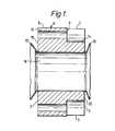
- Figure 1 is a cross-sectional view of one embodiment of the present invention;
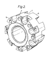
- Figure 2 is a perspective view of the pipe coupling of Figure 1;
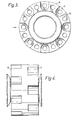
- Figure 3 is an end elevation of the pipe coupling of Figure 1;
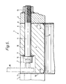
- Figure 4 is a side elevation of the pipe coupling of Figure 1; and
- Figure 5 is a partial cross-sectional view of the pipe coupling of Figures 1 to 4 installed between two pieces of pipework.
- Figure 1 shows the
annular flanges 1 and 2 at the opposed ends of pieces of ship to shore pipework which are to be interconnected by apipe coupling 3 according to the present invention. Thepipe coupling 3 is in the form of an annular body with a coaxial, cylindrical through-bore made of a strong, easily machinable insulating plastics material such as polypenco nylatron GSM with twoend faces body 4 there is a circumferential array of cut-aways such as 7 into the peripheral surface and end surface of thebody 4. The cut-aways 7 are all similar to one another and are equally angularly spaced around the axis of thebody 4 with the cut-aways 7 at one of thebody 4 being aligned with castellatedformations 8 formed by the part of thebody 4 between adjacent cut-aways at the opposite end. It will be appreciated, therefore, that the angular displacement between the two sets of cutaways is half the angular displacement between adjacent cut-aways in each set. - A respective through-
hole 10 extends between theinner end wall 9 of each cut-away, whichend wall 9 is also perpendicular to the axis ofbody 4 and the opposite end of the body. Each through-hole 10 accommodates theshank 11 of a bolt, thehead 12 of which is accommodated in the associated cut-away 7. The threaded part of thebolt 12 extends through the mating flange, such as 2, and is secured by means of anut 13. It will be seen from Figure 2 that each cut-away 7 has a radiallyinner wall portion 14 which conforms to a part cylinder whose axis coincides with that of the corresponding through-hole 10. Apart from being relatively easy to mill, this part cylindrical surface portion accommodates the rotation of akey 15 which may, if necessary, be a specially fabricated allen key, and is used to tighten thebolts 12. It will be appreciated that the fact that eachcastellated formation 8 extends radially outwardly beyond the heads of thebolts 12 in the circumferentially adjacent cut-aways 7 provides a measure of protection for these heads. Also, the fact that theinner end walls 9 at opposite ends of thebody 4 are spaced to opposite sides of the longitudinal medium plane of thebody 4 means that it is difficult for short circuiting bridges to occur between bolts respectively connected to the two opposedflanges 1 and 2. The coupling may be provided with aPTFE liner 16 having a cylindrical middle section accommodated in the through-bore of thebody 4 and twoannular end flanges annular sealing faces away 7. Theliner 16 is intended to protect the main body of the coupling against incompatible products. Theflanges
Claims (7)
Priority Applications (1)
| Application Number | Priority Date | Filing Date | Title |
|---|---|---|---|
| AT83304323T ATE23216T1 (en) | 1983-01-12 | 1983-07-26 | PIPE CONNECTION. |
Applications Claiming Priority (2)
| Application Number | Priority Date | Filing Date | Title |
|---|---|---|---|
| GB8300730 | 1983-01-12 | ||
| GB08300730A GB2133490B (en) | 1983-01-12 | 1983-01-12 | Pipe coupling |
Publications (2)
| Publication Number | Publication Date |
|---|---|
| EP0113948A1 true EP0113948A1 (en) | 1984-07-25 |
| EP0113948B1 EP0113948B1 (en) | 1986-10-29 |
Family
ID=10536220
Family Applications (1)
| Application Number | Title | Priority Date | Filing Date |
|---|---|---|---|
| EP83304323A Expired EP0113948B1 (en) | 1983-01-12 | 1983-07-26 | Pipe coupling |
Country Status (5)
| Country | Link |
|---|---|
| EP (1) | EP0113948B1 (en) |
| AT (1) | ATE23216T1 (en) |
| AU (1) | AU1754783A (en) |
| DE (1) | DE3367268D1 (en) |
| GB (1) | GB2133490B (en) |
Cited By (3)
| Publication number | Priority date | Publication date | Assignee | Title |
|---|---|---|---|---|
| EP1964777A4 (en) * | 2005-12-23 | 2014-07-02 | Airbus Operations Sl | Electric insulation device for use in fuel lines |
| US10634269B2 (en) | 2016-07-08 | 2020-04-28 | Thermon Heating Systems, Inc. | Electrically isolating block and flange for rail-heating duct |
| EP3851724A1 (en) | 2020-01-20 | 2021-07-21 | Nexans | Johnston coupling with galvanic separation |
Citations (4)
| Publication number | Priority date | Publication date | Assignee | Title |
|---|---|---|---|---|
| US2859052A (en) * | 1954-11-17 | 1958-11-04 | Western Electric Co | Coupling with flange aligning means |
| GB838464A (en) * | 1957-11-16 | 1960-06-22 | Vauxhall Motors Ltd | Improved coupling and joint for pipes and tubes |
| GB977133A (en) * | 1962-04-04 | 1964-12-02 | Pirelli General Cable Works | Improvements in or relating to flanged pipe couplings |
| US3862771A (en) * | 1973-04-18 | 1975-01-28 | Walter Schwarz | Electrically insulating tube coupling |
-
1983
- 1983-01-12 GB GB08300730A patent/GB2133490B/en not_active Expired
- 1983-07-26 EP EP83304323A patent/EP0113948B1/en not_active Expired
- 1983-07-26 DE DE8383304323T patent/DE3367268D1/en not_active Expired
- 1983-07-26 AT AT83304323T patent/ATE23216T1/en not_active IP Right Cessation
- 1983-08-03 AU AU17547/83A patent/AU1754783A/en not_active Abandoned
Patent Citations (4)
| Publication number | Priority date | Publication date | Assignee | Title |
|---|---|---|---|---|
| US2859052A (en) * | 1954-11-17 | 1958-11-04 | Western Electric Co | Coupling with flange aligning means |
| GB838464A (en) * | 1957-11-16 | 1960-06-22 | Vauxhall Motors Ltd | Improved coupling and joint for pipes and tubes |
| GB977133A (en) * | 1962-04-04 | 1964-12-02 | Pirelli General Cable Works | Improvements in or relating to flanged pipe couplings |
| US3862771A (en) * | 1973-04-18 | 1975-01-28 | Walter Schwarz | Electrically insulating tube coupling |
Cited By (3)
| Publication number | Priority date | Publication date | Assignee | Title |
|---|---|---|---|---|
| EP1964777A4 (en) * | 2005-12-23 | 2014-07-02 | Airbus Operations Sl | Electric insulation device for use in fuel lines |
| US10634269B2 (en) | 2016-07-08 | 2020-04-28 | Thermon Heating Systems, Inc. | Electrically isolating block and flange for rail-heating duct |
| EP3851724A1 (en) | 2020-01-20 | 2021-07-21 | Nexans | Johnston coupling with galvanic separation |
Also Published As
| Publication number | Publication date |
|---|---|
| GB8300730D0 (en) | 1983-02-16 |
| GB2133490B (en) | 1986-02-26 |
| ATE23216T1 (en) | 1986-11-15 |
| GB2133490A (en) | 1984-07-25 |
| DE3367268D1 (en) | 1986-12-04 |
| AU1754783A (en) | 1984-07-19 |
| EP0113948B1 (en) | 1986-10-29 |
Similar Documents
| Publication | Publication Date | Title |
|---|---|---|
| US4302066A (en) | Safety locking means for industrial grade electrical connectors | |
| US4654747A (en) | Dielectric isolation of metallic conduits | |
| US3104276A (en) | Through-bolt joint for bus duct | |
| US5197903A (en) | Firewall connector | |
| US20080101886A1 (en) | Bolt Assembly | |
| US4316053A (en) | Pipe couplings and coupling gaskets | |
| US4348956A (en) | Artillery shell comprising two sections having complementary coupling members for connecting the sections together | |
| CA2019458A1 (en) | Rigid or flexible coupling for pipes | |
| GB2230835A (en) | Pipe flange connections | |
| US20100173512A1 (en) | High power, single pole electrical connector | |
| US4575129A (en) | Pipelock | |
| EP0113948B1 (en) | Pipe coupling | |
| US5213520A (en) | Firewall connector | |
| US5333964A (en) | Slip joint connector | |
| US4420202A (en) | Plural phase cable couplers | |
| EP0034599B1 (en) | A chain joining shackle or link | |
| CN107706681B (en) | Energy distribution device for power supply of reefer containers | |
| US4572548A (en) | Pipelock | |
| US3454287A (en) | Insulated coupling for grooved end pipe | |
| US6129391A (en) | Plastic coupling for plastic pipe having a completed installation signal | |
| US12607281B2 (en) | Pipe coupling | |
| EP1964777B1 (en) | Electric insulation device for use in fuel lines | |
| CA2142559A1 (en) | Supporting insulator having an outer ring | |
| US6499774B1 (en) | Radial wedge flange clamp | |
| US5447453A (en) | Field Serviceable mining cable coupler |
Legal Events
| Date | Code | Title | Description |
|---|---|---|---|
| PUAI | Public reference made under article 153(3) epc to a published international application that has entered the european phase |
Free format text: ORIGINAL CODE: 0009012 |
|
| 17P | Request for examination filed |
Effective date: 19840502 |
|
| AK | Designated contracting states |
Designated state(s): AT BE CH DE FR GB IT LI LU NL SE |
|
| GRAA | (expected) grant |
Free format text: ORIGINAL CODE: 0009210 |
|
| AK | Designated contracting states |
Kind code of ref document: B1 Designated state(s): AT BE CH DE FR IT LI LU NL SE |
|
| PG25 | Lapsed in a contracting state [announced via postgrant information from national office to epo] |
Ref country code: LI Effective date: 19861029 Ref country code: IT Free format text: LAPSE BECAUSE OF FAILURE TO SUBMIT A TRANSLATION OF THE DESCRIPTION OR TO PAY THE FEE WITHIN THE PRESCRIBED TIME-LIMIT;WARNING: LAPSES OF ITALIAN PATENTS WITH EFFECTIVE DATE BEFORE 2007 MAY HAVE OCCURRED AT ANY TIME BEFORE 2007. THE CORRECT EFFECTIVE DATE MAY BE DIFFERENT FROM THE ONE RECORDED. Effective date: 19861029 Ref country code: CH Effective date: 19861029 Ref country code: AT Effective date: 19861029 |
|
| REF | Corresponds to: |
Ref document number: 23216 Country of ref document: AT Date of ref document: 19861115 Kind code of ref document: T |
|
| PG25 | Lapsed in a contracting state [announced via postgrant information from national office to epo] |
Ref country code: SE Effective date: 19861031 |
|
| REF | Corresponds to: |
Ref document number: 3367268 Country of ref document: DE Date of ref document: 19861204 |
|
| ET | Fr: translation filed | ||
| REG | Reference to a national code |
Ref country code: CH Ref legal event code: PL |
|
| PG25 | Lapsed in a contracting state [announced via postgrant information from national office to epo] |
Ref country code: LU Free format text: LAPSE BECAUSE OF NON-PAYMENT OF DUE FEES Effective date: 19870731 |
|
| PLBE | No opposition filed within time limit |
Free format text: ORIGINAL CODE: 0009261 |
|
| STAA | Information on the status of an ep patent application or granted ep patent |
Free format text: STATUS: NO OPPOSITION FILED WITHIN TIME LIMIT |
|
| 26N | No opposition filed | ||
| PGFP | Annual fee paid to national office [announced via postgrant information from national office to epo] |
Ref country code: FR Payment date: 19930730 Year of fee payment: 11 |
|
| PGFP | Annual fee paid to national office [announced via postgrant information from national office to epo] |
Ref country code: NL Payment date: 19930731 Year of fee payment: 11 |
|
| PGFP | Annual fee paid to national office [announced via postgrant information from national office to epo] |
Ref country code: DE Payment date: 19930806 Year of fee payment: 11 |
|
| PGFP | Annual fee paid to national office [announced via postgrant information from national office to epo] |
Ref country code: BE Payment date: 19930901 Year of fee payment: 11 |
|
| PG25 | Lapsed in a contracting state [announced via postgrant information from national office to epo] |
Ref country code: BE Effective date: 19940731 |
|
| BERE | Be: lapsed |
Owner name: POWELL DUFFRYN TERMINALS LTD Effective date: 19940731 |
|
| PG25 | Lapsed in a contracting state [announced via postgrant information from national office to epo] |
Ref country code: NL Effective date: 19950201 |
|
| NLV4 | Nl: lapsed or anulled due to non-payment of the annual fee | ||
| PG25 | Lapsed in a contracting state [announced via postgrant information from national office to epo] |
Ref country code: FR Effective date: 19950331 |
|
| PG25 | Lapsed in a contracting state [announced via postgrant information from national office to epo] |
Ref country code: DE Effective date: 19950401 |
|
| REG | Reference to a national code |
Ref country code: FR Ref legal event code: ST |