EP3849909B1 - Verfahren und system zur anordnung von artikeln - Google Patents
Verfahren und system zur anordnung von artikeln Download PDFInfo
- Publication number
- EP3849909B1 EP3849909B1 EP19860001.7A EP19860001A EP3849909B1 EP 3849909 B1 EP3849909 B1 EP 3849909B1 EP 19860001 A EP19860001 A EP 19860001A EP 3849909 B1 EP3849909 B1 EP 3849909B1
- Authority
- EP
- European Patent Office
- Prior art keywords
- article
- articles
- bucket
- finger
- sidewall
- Prior art date
- Legal status (The legal status is an assumption and is not a legal conclusion. Google has not performed a legal analysis and makes no representation as to the accuracy of the status listed.)
- Active
Links
Images


Classifications
-
- B—PERFORMING OPERATIONS; TRANSPORTING
- B65—CONVEYING; PACKING; STORING; HANDLING THIN OR FILAMENTARY MATERIAL
- B65G—TRANSPORT OR STORAGE DEVICES, e.g. CONVEYORS FOR LOADING OR TIPPING, SHOP CONVEYOR SYSTEMS OR PNEUMATIC TUBE CONVEYORS
- B65G47/00—Article or material-handling devices associated with conveyors; Methods employing such devices
- B65G47/22—Devices influencing the relative position or the attitude of articles during transit by conveyors
- B65G47/26—Devices influencing the relative position or the attitude of articles during transit by conveyors arranging the articles, e.g. varying spacing between individual articles
- B65G47/28—Devices influencing the relative position or the attitude of articles during transit by conveyors arranging the articles, e.g. varying spacing between individual articles during transit by a single conveyor
-
- B—PERFORMING OPERATIONS; TRANSPORTING
- B65—CONVEYING; PACKING; STORING; HANDLING THIN OR FILAMENTARY MATERIAL
- B65B—MACHINES, APPARATUS OR DEVICES FOR, OR METHODS OF, PACKAGING ARTICLES OR MATERIALS; UNPACKING
- B65B35/00—Supplying, feeding, arranging or orientating articles to be packaged
- B65B35/30—Arranging and feeding articles in groups
-
- B—PERFORMING OPERATIONS; TRANSPORTING
- B65—CONVEYING; PACKING; STORING; HANDLING THIN OR FILAMENTARY MATERIAL
- B65B—MACHINES, APPARATUS OR DEVICES FOR, OR METHODS OF, PACKAGING ARTICLES OR MATERIALS; UNPACKING
- B65B35/00—Supplying, feeding, arranging or orientating articles to be packaged
- B65B35/56—Orientating, i.e. changing the attitude of, articles, e.g. of non-uniform cross-section
-
- B—PERFORMING OPERATIONS; TRANSPORTING
- B65—CONVEYING; PACKING; STORING; HANDLING THIN OR FILAMENTARY MATERIAL
- B65B—MACHINES, APPARATUS OR DEVICES FOR, OR METHODS OF, PACKAGING ARTICLES OR MATERIALS; UNPACKING
- B65B5/00—Packaging individual articles in containers or receptacles, e.g. bags, sacks, boxes, cartons, cans, jars
- B65B5/06—Packaging groups of articles, the groups being treated as single articles
-
- B—PERFORMING OPERATIONS; TRANSPORTING
- B65—CONVEYING; PACKING; STORING; HANDLING THIN OR FILAMENTARY MATERIAL
- B65G—TRANSPORT OR STORAGE DEVICES, e.g. CONVEYORS FOR LOADING OR TIPPING, SHOP CONVEYOR SYSTEMS OR PNEUMATIC TUBE CONVEYORS
- B65G47/00—Article or material-handling devices associated with conveyors; Methods employing such devices
- B65G47/02—Devices for feeding articles or materials to conveyors
- B65G47/04—Devices for feeding articles or materials to conveyors for feeding articles
- B65G47/06—Devices for feeding articles or materials to conveyors for feeding articles from a single group of articles arranged in orderly pattern, e.g. workpieces in magazines
- B65G47/08—Devices for feeding articles or materials to conveyors for feeding articles from a single group of articles arranged in orderly pattern, e.g. workpieces in magazines spacing or grouping the articles during feeding
- B65G47/084—Devices for feeding articles or materials to conveyors for feeding articles from a single group of articles arranged in orderly pattern, e.g. workpieces in magazines spacing or grouping the articles during feeding grouping articles in a predetermined 2-dimensional pattern
- B65G47/086—Devices for feeding articles or materials to conveyors for feeding articles from a single group of articles arranged in orderly pattern, e.g. workpieces in magazines spacing or grouping the articles during feeding grouping articles in a predetermined 2-dimensional pattern cubiform articles
-
- B—PERFORMING OPERATIONS; TRANSPORTING
- B65—CONVEYING; PACKING; STORING; HANDLING THIN OR FILAMENTARY MATERIAL
- B65G—TRANSPORT OR STORAGE DEVICES, e.g. CONVEYORS FOR LOADING OR TIPPING, SHOP CONVEYOR SYSTEMS OR PNEUMATIC TUBE CONVEYORS
- B65G47/00—Article or material-handling devices associated with conveyors; Methods employing such devices
- B65G47/52—Devices for transferring articles or materials between conveyors i.e. discharging or feeding devices
- B65G47/68—Devices for transferring articles or materials between conveyors i.e. discharging or feeding devices adapted to receive articles arriving in one layer from one conveyor lane and to transfer them in individual layers to more than one conveyor lane or to one broader conveyor lane, or vice versa, e.g. combining the flows of articles conveyed by more than one conveyor
- B65G47/681—Devices for transferring articles or materials between conveyors i.e. discharging or feeding devices adapted to receive articles arriving in one layer from one conveyor lane and to transfer them in individual layers to more than one conveyor lane or to one broader conveyor lane, or vice versa, e.g. combining the flows of articles conveyed by more than one conveyor from distinct, separate conveyor lanes
-
- B—PERFORMING OPERATIONS; TRANSPORTING
- B65—CONVEYING; PACKING; STORING; HANDLING THIN OR FILAMENTARY MATERIAL
- B65B—MACHINES, APPARATUS OR DEVICES FOR, OR METHODS OF, PACKAGING ARTICLES OR MATERIALS; UNPACKING
- B65B21/00—Packaging or unpacking of bottles
- B65B21/02—Packaging or unpacking of bottles in or from preformed containers, e.g. crates
- B65B21/025—Packaging or unpacking of bottles in or from preformed containers, e.g. crates the bottles being arranged in a head-to-bottom formation
-
- B—PERFORMING OPERATIONS; TRANSPORTING
- B65—CONVEYING; PACKING; STORING; HANDLING THIN OR FILAMENTARY MATERIAL
- B65B—MACHINES, APPARATUS OR DEVICES FOR, OR METHODS OF, PACKAGING ARTICLES OR MATERIALS; UNPACKING
- B65B35/00—Supplying, feeding, arranging or orientating articles to be packaged
- B65B35/30—Arranging and feeding articles in groups
- B65B35/44—Arranging and feeding articles in groups by endless belts or chains
Definitions
- the present disclosure generally relates to systems and methods for arranging articles prior to loading the articles into cartons. More specifically, the present disclosure is directed to methods and systems for arranging the articles to be in a compact and reliable configuration.
- US 6,446,416 A discloses a bucket on a bucket conveyor that has a movable member or wall movable to a laid down position for receiving a horizontally disposed item. The member or wall is moved to reorient the item into an upright position for loading into a carton with another item later introduced into the bucket on another side of the movable member from the first item. Multiple items, inserts and/or multiple products can be handled. Prior art methods and systems, however, still leave room for improvement. According to various aspects disclosed herein, the invention is directed to a method of arranging articles and a system for arranging articles as recited in the independent claims. Further embodiments are recited in the dependent claims.
- the disclosure is directed to a method of arranging articles according to claim 1 and a system for arranging articles according to claim 17.
- the present disclosure generally relates to a system and method of arranging articles prior to loading the articles into cartons.
- the system according to the present disclosure can accommodate articles of any shape.
- the articles can be containers, bottles, cans, etc.
- the articles can be used for packaging food and beverage products, for example.
- the articles can be made from materials suitable in composition for packaging the particular food or beverage item, and the materials include, but are not limited to, aluminum and/or other metals; glass; plastics such as PET, LDPE, LLDPE, HDPE, PP, PS, PVC, EVOH, and Nylon; and the like, or any combination thereof.
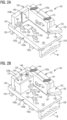
- Figs. 1-11 generally illustrate an example embodiment of a system and method 100 for arranging articles or containers C for being loaded into cartons (not shown) in accordance with the disclosure.
- the system 100 can be included in a continuous packaging machine for packaging the articles C for storage, shipping, and/or sale.
- the packaging machine can continuously, substantially continuously, or intermittently (e.g., indexed) feed articles C to the system 100, which arranges the articles C as described below, and then transfers the arranged articles C to a carton (not shown), wherein the carton and the articles form a package.
- the articles C e.g., as shown in Figs.
- each article C can be in the form of tubs or cups having tapered sides S so that the cups are narrower at their bottoms B than at their tops T.
- the top T of each article C can have a rim R and a lid L (e.g., a foil or other suitable lid) that can seal the top T at the rim R.
- the articles C can be for containing a product for brewing a beverage (e.g., coffee, tea, cocoa, etc.) in a brewing system (e.g., K-Cup pods for single-cup and/or multi-cup brewing systems available from Keurig of Burlington, MA, or other suitable containers and systems).
- the buckets 101 can interact with an actuating cam assembly 111, which can actuate the buckets 101 to at least partially arrange the articles C to be in a more compact configuration.
- the articles C can be removed from the bucket 101 in the compact configuration by a robot arm (not shown) or other suitable apparatus and loaded into a carton (not shown).
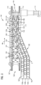
- the buckets 101 can be returned to the upstream end 103 by the conveyor assembly 107 where the buckets can interact with a reset cam assembly 112 that can prepare the buckets 101 for receiving the articles C.
- the actuating cam assembly 111 and the reset cam assembly can be mounted to respective downstream and upstream ends of a cam base plate 110 ( Figs. 1 and 6-11 ).
- the buckets 101 are mounted to two belts or chains 113 of the conveyor assembly 107, which carries the buckets 101 in the machine direction M on top of the conveyor assembly 107 and returns the buckets 101 from the downstream end 105 to the upstream end 103 on an underside of the conveyor assembly 107 in an endless loop.
- the conveyor assembly 107 can include a motor 115 or other suitable apparatus for moving the chains 113. While Fig. 1 shows buckets 101 only on the top side of the conveyor assembly 107, the system 100 can include buckets 101 mounted along the entire conveyor assembly 107.
- the conveyor assembly 107 could be otherwise shaped, positioned, arranged, and/or configured without departing from the disclosure.
- the bucket 101 can include a base 121 (e.g., a base plate), a sidewall 123, a translation plate 125, and a plurality of fingers 127a, 127b, 127c.
- brackets 129 can be secured (e.g., bolted) to the base 121 and can extend downwardly from the base 121 for being secured (e.g., bolted) to the chains 113 of the conveyor assembly 107 ( Fig. 1 ).
- Figs. 1 As shown in Figs.
- the bucket 101 is configured for receiving six articles C in a single layer in a 2x3 arrangement, but it is understood that the bucket 101 may be sized and shaped to hold articles of a different or same quantity in more than one layer and/or in different row/column arrangements (e.g., 1x6, 3x4, 2x6, 4x6, 3x8, 2x6x2, 3x4x2, 2x9, 3x6, etc.).
- the bucket 101 can receive a spacer insert 131 that can engage the translation plate 125, as described in more detail below, so that the bucket 101 is configured to receive four articles in a 2x2 arrangement when the spacer insert 129 is included.
- the sidewall 123 can extend upwardly from the base 121 on a downstream side of the bucket 101.
- the sidewall 123 can be secured (e.g., bolted) to the base 121.
- a wedge 133 can extend from the sidewall 123 (e.g., on a loading or article-receiving side of the bucket 101) and can have a generally orthogonal downstream side 135, a generally orthogonal upstream side 137, and an oblique side 139 extending between the sides 135, 137.
- the orthogonal sides 135, 137 can extend transverse to the machine direction M. As shown in Fig.
- the wedge 133 is located on the sidewall 123 so that it is spaced from the base 121. Accordingly, the wedge 133 can extend between guides of the article conveyor 109 and downstream guide rails as shown in Figs. 3 and 4 and as described in more detail below. Generally the wedge 133 can help engage articles C as they are loaded into the bucket 101 and guide the engaged articles C onto the base 121.
- the translation plate 125 can be positioned on the base 121 and can be connected to the sidewall 123 by a hinge such as pivot arms 141, which can include two pivot arms 141 at the tops of the translation plate 125 and the sidewall 123 ( Figs. 1-7 and 11 ) and a pivot arm 141 at the bases of the translation plate 125 and the sidewall 123 ( Figs. 5-7 and 11 ).
- the translation plate 125 can be in the form of an L-shaped plate and can be movable in a depression 143 of the base 121.
- the translation plate 125 can include a first portion 125a that extends in a transverse direction that is perpendicular to the machine direction M and a second portion 125b that extends in the machine direction M ( Figs. 2A and 2B ).
- a cam follower 144 can be mounted to an extension 146 extending downwardly from the translation plate 125 through an opening or slot (not shown) in the base 121.
- the cam follower 144 can be configured to interact with the actuating cam assembly 111 and the reset cam assembly 112 as described in more detail below.
- the translation plate 125 can move (e.g., due to the interaction between the cam follower 144 and the actuating cam assembly 111) on the pivot arms 141 from an initial configuration 142a (e.g., a loading configuration) to a secondary configuration 142b (e.g., a compacting configuration) ( Figs. 1 and 3 ).
- the translation plate 125 can be retained in the loading configuration 142a against the sidewall 123 by the interaction between the cam follower 144 and the reset cam assembly 112 as described in more detail below or by any other suitable feature.
- the translation plate 125 can be biased toward the loading configuration 142a against the sidewall 123 by springs (e.g., associated with the pivot arms 141) or any other suitable feature.
- the translation plate 125 In the compacting configuration 142b, the translation plate 125 can be moved away from the sidewall 123 (e.g., in the upstream direction) and toward the loading side of the bucket 101 (e.g., in the transverse direction) in order to compact the articles C in the bucket 101 as discussed in more detail below.
- the translation plate 125 can include a slot or groove 145 that can be vertically oriented and that can receive a tongue 147 of the spacer insert 131 to help retain the spacer insert 131 against the translation plate 125.
- the spacer insert 131 can further include a fastener that engages a bore 151 in the translation plate 125 for further securing the spacer insert 131 to the translation plate 125.
- the fastener can include a biased pin (not shown) that can be biased toward engagement with the bore 151 ( Fig.
- the spacer insert 131 can be configured to take the space of one row of articles C, covering one of the fingers (e.g., finger 127a), so that the bucket 101 is configured for receiving the articles C in a 2x2 arrangement when the spacer insert 131 is used.
- each of the fingers 127a, 127b, 127c can be received in respective slots 153 in the base 121.
- each of the fingers 127a, 127b, 127c can have a respective base arm 155a, 155b, 155c that is pivotably mounted to the base 121 at a pivot point 156 at an end of the base arm 155a, 155b, 155c.
- the base arms 155a and 155c can pivot on an axle 160a at a downstream end of the base arms and the base arm 155b can pivot on an axle 160b at an upstream end of the base arm ( Figs.
- each of the base arms 155a, 155b, 155c can include a downward protrusion 157 and a projection 158 for interacting with the cam assemblies 111, 112 as described in more detail below.
- the base arm 155a, 155b, 155c of each finger 127a, 127b, 127c can pivot about its pivot point 156 from an initial configuration (e.g., a retracted configuration), wherein the top end 159 of each finger 127a, 127b, 127c is disposed in the respective slot 153 below the support surface 161 of the base 121 ( Figs. 1 and 4 ), to a secondary configuration (e.g., an elevated configuration), wherein the top end 159 extends above the support surface 161 of the base 121 ( Figs. 1-2B , 4-7 and 11 ).
- the buckets 101 could be otherwise shaped, positioned, arranged, and/or configured without departing from the disclosure.
- the article conveyor 109 can include a belt conveyor or other suitable apparatus for moving the articles C toward the loading side of the buckets 101 in a plurality of lanes 163a, 163b, 163c.
- the article conveyor 109 includes three lanes 163a, 163b, 163c for a bucket 101 configured to receive three rows of articles C (e.g., in a 2x3 arrangement). Accordingly, each lane 163a, 163b, 163c can provide one row of articles C.
- one or more of the lanes can be deactivated (e.g., blocked) for buckets 101 configured to receive fewer rows of articles C.
- the buckets 101 can include the spacer inserts 131 ( Fig. 1 ) so that they are configured to receive two rows of articles C (e.g., in a 2x2 arrangement) and one of the lanes 163a, 163b, 163c could be deactivated.
- the article conveyor 109 could be reconfigured or replaced to include only two lanes for loading articles C in a 2x2 arrangement when the spacer inserts 131 are included.
- the article conveyor could include more than three lanes and/or each lane could provide more than one row of articles to each bucket.
- each lane 163a, 163b, 163c can supply two articles C so that one is foil up and one is foil down ( Fig. 3 ).
- each subsequent lane can be configured so that the orientations of the articles C are out of phase with the orientations of the articles of the prior, upstream lane.
- the upstream lane 163a can load a foil down article C (the bottom B is visible in Fig. 3 ) followed by a foil up article C (the top T is visible in Fig.
- each of the slots 153 and the respective fingers 127a, 127b, 127c is aligned with (e.g., for abutting) the bottom B of a respective foil up article C when the articles C are fully loaded in the buckets 101.
- the fingers 127a, 127b, 127c could be aligned with foil down and/or foil up articles C.
- the article conveyor 109 includes a plurality of guides 165 that define the lanes (e.g., four guides 165 can define the three lanes 163a, 163b, 163c) and guide the articles C as they move along the lanes 163a, 163b, 163c.
- at least the downstream ends of each of the guides 165 can include an upper portion 167a spaced from a lower portion 167b to provide a clearance gap 169 so that the wedges 133 can pass between the portions 167a, 167b in the gap 169 as the buckets 101 move past the guides 165.
- the articles C can be moved on a conveyor belt (not shown) or any other suitable apparatus for moving the articles C along the guides 165 in the lanes 163a, 163b, 163c.
- a guide rail 171 can extend in the machine direction M from the article conveyor 109 for retaining the articles C in the buckets 101 as the buckets 101 move downstream from the article conveyor 109.
- an upstream end of the guide rail 171 extends from a downstream end of the downstream guide 165 of the downstream lane 163c.
- the guide rail 171 can include an upper portion 173a, and a lower portion 173b spaced apart by a gap 175 for providing clearance for the wedges 133 ( Fig. 4 ).
- the article conveyor 109 and/or the guide rail 171 could be omitted or could be otherwise shaped, positioned, arranged, and/or configured without departing from the disclosure.
- the actuating cam assembly 111 is disposed on the cam base plate 110 proximate the downstream end 105 of the system 100 and is downstream from the article conveyor 109.
- the actuating cam assembly 111 can include a plurality of actuating finger cam surfaces 177a, 177b, 177c for guiding the protrusions 157 of the respective fingers 127a, 127b, 127c from the retracted configuration to the elevated configuration (e.g., so that the tops 159 of the fingers 127a, 127b, 127c extend above the top surface 161 of the base 121).
- each of the finger cam surfaces 177a, 177b, 177c can include an upstream sloped surface portion 179 and a horizontal surface portion 181 extending downstream from the sloped surface portion 179.
- the sloped surface portions 179 can gradually push the respective fingers 127a, 127b, 127c upwardly through the slots 153 by engaging the protrusions 157 and causing the base arms 155a, 155b, 155c to pivot about their pivot points 156.
- the protrusions 157 can slide along the horizontal surface portions 181 of the respective finger cam surfaces 177a, 177b, 177c to maintain the fingers 127a, 127b, 127c in the elevated configuration. As shown in Figs.
- the central cam surface 177b can be offset in the machine direction M from the outer cam surfaces 177a, 177c so that the protrusions 157 of the respective fingers 127a, 127b, 127c engage the respective cam surfaces 177a, 177b, 177c to be moved to the elevated configuration at substantially the same time even though the protrusion 157 of the central finger 127b is located downstream from the protrusions 157 the outer fingers 127a, 127c.
- the protrusions 157 have rounded surfaces for sliding along the cam surfaces.
- a cam follower (not shown) or other suitable feature could be mounted to each of the protrusions for rolling or otherwise moving along the cam surfaces 177a, 177b, 177c.
- the actuating cam assembly 111 can include a translating cam surface 183 for engaging the cam follower 144 of the translation plate 125.
- translating cam surface 183 can include a sloped surface portion 185 and a vertical surface portion 187 so that the cam follower 144 can engage the sloped surface portion 185 to gradually move the translation plate 125 via the extension 146 relative to the sidewall 123 and the base 121 on the pivot arms 141 to the compacting configuration 142b of the bucket 101.
- the cam follower 144 can roll along the vertical surface portion 187 to maintain the translation plate 125 in the compacting configuration 142b. As shown in Figs.
- the translating cam surface 183 can be offset in the machine direction M from the finger cam surfaces 177a, 177b, 177c so that the translation plate 125 is moved to the compacting configuration 142b after the fingers 127a, 127b, 127c are moved to the elevated configuration.
- the cam surfaces 177a, 177b, 177c, 183 extend along blocks that are mounted to the cam base plate 110. As shown in Figs. 6 and 8-10 , the central finger cam surface 177b and the translating cam surface 183 are formed on the same block.
- the actuating cam assembly 111 could be otherwise shaped, positioned, arranged, and/or configured without departing from the disclosure. For example, any suitable number of cam surfaces could be formed on any suitable number of blocks. In another example, the one or more of the cam surfaces could be integrally formed with the cam base plate 110.
- the reset cam assembly 112 is mounted at an upstream end of the cam base plate 110 and includes a plurality of reset cam surfaces 197a, 197b, 197c for moving the respective fingers 127a, 127b, 127c to the retracted configuration (e.g., so that the tops 159 of the fingers 127a, 127b, 127c are moved down into the slots 153 and do not extend above the top surface 161 of the base 121).
- the fingers 127a, 127b, 127c can move to the retracted configuration due to gravity.
- the reset cam surfaces 197a, 197b, 197c can engage the respective fingers 127a, 127b, 127c to move them to the retracted configuration.
- each of the reset cam surfaces 197a, 197b, 197c can include a sloped surface 199 that is angled downwardly from the upstream end 103 (e.g., each of the sloped surfaces 199 is angled so that its highest point is upstream from its lowest point). Accordingly the sloped surfaces 199 can engage the fingers 127a, 127b, 127c (e.g., at respective projections 158 extending from the protrusions 157 of the respective fingers) and can gradually push the projections 158 downwardly as the bucket 101 moves in the machine direction M. In one embodiment, the downward urging of the sloped surfaces 199 on the projections 158 ( Fig.
- the base arms 155a, 155b, 155c can cause the base arms 155a, 155b, 155c to pivot about their pivot points 156 and to move the tops 159 of the fingers downwardly into the slots 153.
- the fingers 127a, 127b, 127c are configured with cam followers (not shown) (e.g., wherein the projections 158 can be axles for the cam followers in one embodiment), the cam followers can engage the cam surfaces 199 as the bucket 101 moves in the machine direction M.
- the reset cam assembly 112 can include a transverse reset cam surface 203 for engaging the cam follower 144 of the translation plate 125 and moving the translation plate 125 to the loading configuration 142a of the bucket 101.
- the transverse reset cam surface 203 can include a sloped surface portion 205 and a vertical surface portion 207 so that the cam follower 144 can engage the sloped surface portion 205 to gradually move the translation plate 125 via the extension 146 relative to the sidewall 123 and the base 121 on the pivot arms 141 to the loading configuration 142a.
- the cam follower 144 can roll along the vertical surface portion 207 to maintain the translation plate 125 in the loading configuration 142a. As shown in Fig.
- the transverse reset cam surface 203 can extend to a downstream end that is proximate to the upstream end of the translating cam surface 183 of the actuating cam assembly 111. Accordingly, the transverse reset cam surface 203 can maintain the translation plate 125 in the loading configuration 142a via the cam follower 144 and the extension 146 until the translating cam surface 183 engages the cam follower 144 and moves the translation plate 125 to the compacting configuration 142b.
- the cam surfaces 197a, 197b, 197c, 203 extend along blocks that are mounted to the cam base plate 110. As shown in Figs. 8-10 , the reset cam surfaces 197a, 197b are formed on the same block.
- the reset cam assembly 112 could be otherwise shaped, positioned, arranged, and/or configured without departing from the disclosure. For example, any suitable number of cam surfaces could be formed on any suitable number of blocks. In another example, the one or more of the cam surfaces could be integrally formed with the cam base plate 110. In another example, the reset cam assembly 112 could be spaced downstream from the upstream end 103 and configured to move the fingers and the translation plate to the loading configuration 142a prior to or when the articles C are loaded into the buckets 101.
- the reset cam assembly 112 could be omitted and the fingers 127a, 127b, 127c can be biased to the retracted configuration by springs or other suitable features and/or the translation plate 125 can be biased to the loading configuration by springs or other suitable features.
- the buckets 101 cooperate with one another to form an interior receiving space 190 that receives the articles C.
- the receiving space 190 can be defined by the base 121 and the translation plate 125 of one bucket 101 and the sidewall 123 of an adjacent bucket 101 that is upstream from the receiving space 190.
- the loading side of the buckets 101 can be at least partially closed by the guide rail 171 to further define the receiving space 190 as the buckets 101 move downstream from the article conveyor 109 after the articles C are loaded into the receiving space 190.
- each of the buckets 101 can include two bumpers 191 on the translation plate 125 ( Figs.
- each of the bumpers 191, 193 can be aligned with the fingers 127a, 127b, 127c so that the bumpers 191, 193 can engage the foil up articles C in the receiving space 190.
- the receiving spaces 190 could be otherwise shaped, positioned, arranged, and/or configured without departing from the disclosure.
- the bumpers 191, 193 could be configured to engage the foil up articles and/or the foil down articles.
- the buckets 101 can move in the machine direction M from the upstream end 103 so that adjacent buckets 101 are proximate one another (e.g., closely spaced from one another as shown in Figs. 1 , 3 , and 5 ) and/or abut one another and so that the translation plate 125 and the sidewall 123 of the adjacent buckets form the receiving spaces 190. As shown in Fig.
- the projections 158 of the fingers 127a, 127b, 127c can engage the respective cam surfaces 197a, 197b, 197c to move the fingers 127a, 127b, 127c into the retracted configuration, and the cam follower 144 can engage the cam surface 203 to move the translation plate 125 to the loading configuration 142a.
- the buckets 101 are prepared to receive the articles C. As shown in Figs.
- two articles C e.g., a foil up article followed by a foil down article
- the angled portion of the guide 165 at the downstream side of the lane 163b can push the articles C from the second lane 163b into the receiving space 190 as the buckets 101 move in the machine direction M to form the second row of articles C, and the second row can push the articles C in the first row farther into the receiving space 190.
- the wedges 133 can move through the third lane 163c to capture two end articles C (e.g., a foil down article followed by a foil up article) to form the third row of articles C.
- the angled portion of the final guide 165 can further push the articles C into the receiving space 190 to fully load the articles C into the receiving space 190.
- the buckets 101 can move downstream from the article conveyor 109 so that the loading side of the buckets 101 is closed by the guide rail 171. Accordingly, the guide rail 171 can cooperate with the translation plate 125 and the sidewall 123 to enclose the receiving space 190 with the wedges 133 moving through the gap 175 of the guide rail 171 ( Fig. 4 ).
- the protrusions 157 of the fingers 127a, 127b, 127c can engage the respective cam surfaces 177a, 177b, 177c so that the protrusions 157 slide upwardly along the sloped surface portions 179 to the horizontal surface portions 181 to move the fingers 127a, 127b, 127c upwardly against their biases to the elevated configuration (e.g., as shown in Figs. 6 and 7 ). Accordingly, the tops 159 of the fingers 127a, 127b, 127c move upwardly through the slots 153 to extend above the top surface 161 of the base 121, thereby pushing upwardly on the bottoms of the foil up articles C. As shown in Fig. 5 , the foil up articles are then elevated with respect to the foil down articles C, which remain in contact with the base 121.
- the rims R of the elevated foil up articles C are spaced above the bottoms B of the foil down articles, and the rims R of the foil down articles C are spaced below the bottoms B of the elevated foil up articles C.
- the sloped sides S of the adjacent articles C can allow narrower portions of the articles to be aligned.
- the cam follower 144 can move past the downstream end of the transverse reset cam surface 203, which was retaining the translation plate 125 in the loading configuration 142a, and can engage the sloped portion 185 of the translating cam surface 183 to move the cam follower 144 in the transverse direction that is transverse to the machine direction M to the vertical surface portion 187 of the translating cam surface 183.
- This movement of the cam follower 144 can move the translation plate 125 via the extension 146 from the loading configuration 142a to the compacting configuration 142b, wherein the translation plate 125 moves on the pivot arms 141 away from the sidewall 123 to which it is connected.
- the translation plate 125 can move on the pivot arms 141 toward the guide rail 171 and the sidewall 123 of the upstream bucket 101 (e.g., diagonally into the receiving space 190). This movement of the translation plate 125 can compact the arrangement of the articles C between the translation plate 125 of the bucket 101, the guide rail 171, and the sidewall 123 of the upstream bucket 101. The articles C can then engage one another at the sloped sides as shown in Fig. 5 , limiting or removing any slack or freedom of movement between the arranged articles C.
- the protrusions 157 and the cam follower 144 can continue to move along the cam surfaces 177a, 177b, 177c, 183 to retain the arrangement of the articles C in the compacted configuration as the buckets 101 move in the machine direction M and are in engagement with the cam assembly 111.
- the compacting of the articles C in the 2x3 arrangement can allow the arrangement to be more reliably acquired by the robot arm since there is less room for the articles C to move relative to one another in the arrangement when the articles are compacted. Accordingly, the locations of the articles C are more predictable in the interior space when the arrangement is compacted to limit or remove freedom of movement of the articles relative to one another.
- the carton into which the articles C are ultimately loaded by the robot arm is configured for holding the articles C in the uncompacted arrangement (e.g., wherein none of the articles is elevated with respect to the other articles) and has an opening that is wider than the footprint of the compacted arrangement of articles C as acquired from the interior space 190 by the robot arm.
- the compacted arrangement then can more easily fit through the opening and be inserted into the carton than an uncompacted arrangement since the compacted articles are less likely to catch on an edge of the carton as they are loaded into it.
- the robot arm can disengage from the articles and the articles can settle in the carton into an uncompacted arrangement in one embodiment.
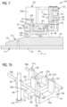
- Figs. 12 and 13 are schematic perspective views of a bucket 301 and two interior spaces 390a, 390b according to a second embodiment of the disclosure.
- the second embodiment is generally similar to the first embodiment, except for variations noted and variations that will be apparent to one of ordinary skill in the art. Accordingly, similar or identical features of the embodiments have been given like or similar reference numbers.
- the bucket 301 can be for use in the system 100 or in a similar system. As shown in Figs. 12 and 13 , the bucket 301 can be similar to the buckets 101 of the first embodiment except that the bucket 301 is configured for receiving the articles C in two separate 1 ⁇ 4 arrangements in the two receiving spaces 390a, 390b.
- the bucket 301 can be configured to be wider than the buckets 101 of the first embodiment in the direction that is transverse to the machine direction so that each of the interior spaces 390a, 390b of the bucket 301 is configured to receive two foil up articles C alternating with two foil down articles C in a single column (e.g., in four rows having one article C each).
- the foil up articles C in the receiving space 390b are aligned with the slots 153 for engaging the fingers 127a, 127c.
- the finger 127b can be omitted and/or deactivated in one embodiment (e.g., the cam surface 177b could be omitted).
- the foil up articles C in the receiving space 390a could be aligned with slots (not shown) for engaging additional figures (not shown).
- the foil up articles in the receiving space 390a can be aligned with the foil down articles in the receiving space 390b and the foil down articles in the receiving space 390a can be aligned with the foil up articles in the receiving space 390b.
- the foil up articles and the foil down articles in the receiving space 390a could be aligned with the respective foil up article and foil down articles in the receiving space 390b.
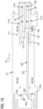
- the sidewall 123 is omitted in the bucket 301 and the translation plate 325 includes a first portion 325a extending transverse to the machine direction M, a second portion 325b extending in the machine direction M from an end of the first portion 325a, and a third portion 325c extending from the second portion 325b in the transverse direction (e.g., parallel to the first portion 325a).
- the first portion 325a and the third portion 325c can cooperate to at least partially form the first receiving space 390a.
- the third portion 390a further can cooperate with the first portion 325a of the translation plate 325 of an adjacent upstream bucket 301 to at least partially form the second receiving space 390b.
- An extension and cam follower (not shown) that are similar or identical to the extension 146 and cam follower 144 of the first embodiment can extend from the translation plate 325 through the base 121.
- the extension and the cam follower can be constrained to move (e.g., due to interaction with the cam surface 183) in the transverse direction since the translation plate 325 is not hinged to a sidewall (e.g., does not need to pivot on a hinge) and since the arrangement of articles includes only one column and the articles are compacted in only the transverse direction.
- the wedges 333 can extend from each of the portions 325a, 325c of the translation plate 325 and can operate similarly to the wedges 133 of the first embodiment.
- the articles C can be loaded into the interior spaces 390a, 390b in a similar manner as in the first embodiment and the foil up articles C can be elevated relative to the foil down articles C by respective fingers in a similar manner as in the first embodiment.
- the translation plate 325 can be moved only in the direction transverse to the machine direction M when the cam follower engages the translating cam surface 183. Accordingly, the translation plate 325 can compact the articles C in the 1 ⁇ 4 configuration in the direction transverse to the machine direction.
- the bucket 301 and/or the interior spaces 390a, 390b could be omitted or could be otherwise shaped, positioned, arranged, and/or configured without departing from the disclosure.
Landscapes
- Engineering & Computer Science (AREA)
- Mechanical Engineering (AREA)
Claims (28)
- Verfahren zum Anordnen von Artikeln (C), wobei das Verfahren umfasst:Verschieben einer Schaufel (101, 301) in einer Maschinenrichtung (M) auf einer Förderanordnung (107), wobei die Schaufel (101, 301) eine Translationsplatte (125, 325), mindestens einen Finger (127a, 127b, 127c), und einen Aufnahmeraum (190, 390a, 390b) umfasst,Laden einer Mehrzahl von Artikeln (C) in eine Anordnung von Artikeln (C) in den Aufnahmeraum (190, 390a, 390b), während sich die Schaufeldie Schaufel (101, 301) in die Maschinenrichtung (M) bewegt, wobei die Anordnung von Artikeln (C) mindestens einen ersten Artikel (C) und einen zweiten Artikel (C) der Mehrzahl von Artikeln (C) umfasst,Anheben zumindest des ersten Artikels (C) in Bezug auf den zweiten Artikel (C) im Aufnahmeraum (190, 390a, 390b) der Schaufel (101, 301) mit dem Finger (127a, 127b, 127c), undVerdichtung der Anordnung von Artikeln (C) in der Schaufel (101, 301) mit der Translationsplatte (125, 325).
- Verfahren nach Anspruch 1, wobei das Verdichten der Anordnung von Artikeln (C) ein Bewegen zumindest des ersten Artikels (C) relativ zum zweiten Artikel (C) umfasst.
- Verfahren nach Anspruch 1, wobei jeder Artikel (C) der Mehrzahl von Artikeln (C) einen Rand (R), einen Boden (B), der dem Rand (R) gegenüberliegend angeordnet ist, und eine Seite (S), die sich vom Rand (R) zum Boden (B) nach innen verjüngt, aufweist.
- Verfahren nach Anspruch 3, wobei das Laden der Mehrzahl von Artikeln (C) ein Ausrichten des ersten Artikels (C) mit dem Rand (R) über dem Boden (B) und ein Ausrichten des zweiten Artikels (C) mit dem Boden (B) über dem Rand (R) umfasst, das Anheben zumindest des ersten Artikels (C) ein Positionieren zumindest des Randes (R) des ersten Artikels (C) höher in Bezug auf den Boden (B) des zweiten Artikels (C) und des Bodens (B) des ersten Artikels (C) höher in Bezug auf den Rand (R) des zweiten Artikels (C) umfasst, und das Verdichten der Anordnung von Artikeln (C) ein Bewegen zumindest eines von dem ersten Artikel (C) und dem zweiten Artikel (C) umfasst, so dass der erste Artikel (C) und der zweite Artikel (C) näher zusammengebracht werden.
- Verfahren nach Anspruch 1, wobei die Schaufel (101, 301) eine Basis (121) umfasst und der Finger (127a, 127b, 127c) sich zumindest teilweise durch die Basis (121) erstreckt, wobei das Anheben zumindest des ersten Artikels (C) ein Bewegen zumindest eines Teils des Fingers (127a, 127b, 127c) nach oben relativ zu der Basis (121) umfasst, um zumindest einen Teil des Fingers (127a, 127b, 127c) mit dem ersten Artikel (C) in Eingriff zu bringen und den ersten Artikel (C) mit dem Finger (127a, 127b, 127c) anzuheben.
- Verfahren nach Anspruch 5, wobei der Finger (127a, 127b, 127c) ein erster Finger (127a, 127b, 127c) ist, die Schaufel (101, 301) mindestens einen zweiten Finger (127a, 127b, 127c) umfasst, der sich zumindest teilweise durch die Basis (121) erstreckt, die Anordnung von Artikeln (C) mindestens einen dritten Artikel (C) der Mehrzahl von Artikeln (C) umfasst, und das Verfahren ferner das Anheben zumindest des dritten Artikels (C) in Bezug auf den zweiten Artikel (C) umfasst, wobei das Anheben zumindest des dritten Artikels (C) ein Bewegen zumindest eines Teils des zweiten Fingers (127a, 127b, 127c) nach oben relativ zu der Basis (121) umfasst, um zumindest einen Teil des zweiten Fingers (127a, 127b, 127c) mit dem dritten Artikel (C) in Eingriff zu bringen und den dritten Artikel (C) mit dem zweiten Finger (127a, 127b, 127c) anzuheben.
- Verfahren nach Anspruch 5, wobei der Finger (127a, 127b, 127c) einen Basisarm (155a, 155b, 155c) umfasst, der schwenkbar mit der Basis (121) an einem Schwenkpunkt (156) verbunden ist, wobei das Bewegen mindestens eines Teils des Fingers (127a, 127b, 127c) nach oben ein Schwenken des Fingers (127a, 127b, 127c) nach oben um den Schwenkpunkt (156) umfasst.
- Verfahren nach Anspruch 5, wobei das Verdichten der Anordnung von Artikeln (C) ein Bewegen der Translationsplatte (125, 325) umfasst, um mit mindestens einem von dem ersten Artikel (C) und dem zweiten Artikel (C) in Eingriff zu kommen und mindestens diesen zu bewegen,
das Bewegen mindestens eines Abschnitts des Fingers (127a, 127b, 127c) und das Bewegen der Translationsplatte (125, 325) jeweils ein In-Eingriff-Bringen mindestens eines Abschnitts des jeweiligen Fingers (127a, 127b, 127c) und der Translationsplatte (125, 325) mit einer jeweiligen Nockenfläche (177a, 177b, 177c, 183) umfassen. - Verfahren nach Anspruch 1, wobei die Schaufel (101, 301) einen Boden (121) aufweist, der Boden (121) und die Translationsplatte (125, 325) zusammenwirken, um zumindest teilweise den Aufnahmeraum (190, 390a, 390b) in der Schaufel (101, 301) zu bilden, das Laden der Mehrzahl von Artikeln (C) ein Positionieren der Mehrzahl von Artikeln (C) in der Anordnung von Artikeln (C) im Aufnahmeraum (190, 390a, 390b) umfasst, und das Verdichten der Anordnung von Artikeln (C) ein Bewegen der Translationsplatte (125, 325) umfasst, um mindestens einen Artikel (C) in der Anordnung von Artikeln (C) im Aufnahmeraum (190, 390a, 390b) in Eingriff zu bringen.
- Verfahren nach Anspruch 9, wobei die Schaufel (101) ferner eine Seitenwand (123) aufweist, die Translationsplatte (125) an der Seitenwand (123) durch mindestens ein Scharnier (141) befestigt ist und das Bewegen der Translationsplatte (125) ein Bewegen der Translationsplatte (125) relativ zu der Seitenwand (123) am Scharnier (141) umfasst.
- Verfahren nach Anspruch 9, wobei die Schaufel (101) eine erste Schaufel (101) ist, die eine erste Seitenwand (123) aufweist, eine zweite Schaufel (101) eine zweite Seitenwand (123) aufweist, die zweite Seitenwand (123) mit der Translationsplatte (125) und dem Boden (121) der ersten Schaufel (101) zusammenwirkt, um zumindest teilweise den Aufnahmeraum (190) zu bilden, und das Bewegen der Translationsplatte (125) ein Bewegen der Translationsplatte (125) relativ zu der ersten Seitenwand (123) und der zweiten Seitenwand (123) umfasst.
- Verfahren nach Anspruch 11, wobei die erste Schaufel (101) einen ersten Keil (133) umfasst, der sich von der ersten Seitenwand (123) aus erstreckt, die zweite Schaufel (101) einen zweiten Keil (133) umfasst, der sich von der zweiten Seitenwand (123) aus erstreckt, und das Laden der Mehrzahl von Artikeln (C) ein Eingreifen in Artikel (C) der Mehrzahl von Artikeln (C) zwischen dem ersten Keil (133) und dem zweiten Keil (133) und ein Bewegen der Artikel (C) in den Aufnahmeraum (190) umfasst.
- Verfahren nach Anspruch 11, ferner umfassend ein Bewegen der Mehrzahl von Artikeln (C) in Richtung der Förderanordnung (107) auf einem Artikelförderer (109), wobei das Bewegen der Schaufel (101) in der Maschinenrichtung (M) ein Bewegen der ersten Schaufel (101) und der zweiten Schaufel (101) relativ zu dem Artikelförderer (109) umfasst, das Laden der Mehrzahl von Artikeln (C) ein In-Eingriff-Bringen von Artikeln (C) der Mehrzahl von Artikeln (C) vom Artikelförderer (109) zwischen einem ersten Keil (133), der sich von der ersten Seitenwand (123) erstreckt, und einem zweiten Keil (133), der sich von der zweiten Seitenwand (123) erstreckt, während der Bewegung der ersten Schaufel (101) und der zweiten Schaufel (101) relativ zu dem Artikelförderer (109) umfasst,eine Führungsschiene (171) erstreckt sich in der Maschinenrichtung (M) vom Artikelförderer (109), und das Verfahren ferner ein Bewegen der ersten Schaufel (101) und der zweiten Schaufel (101) entlang der Führungsschiene (171) umfasst, so dass die Führungsschiene (171) mit der Translationsplatte (125) und der zweiten Seitenwand (123) zusammenwirkt, um den Aufnahmeraum (190) zumindest teilweise zu umschließen,die Translationsplatte (125) umfasst einen ersten Abschnitt (125a), der sich parallel zu der ersten Seitenwand (123) und der zweiten Seitenwand (123) erstreckt, und einen zweiten Abschnitt (125b), der sich senkrecht zum ersten Abschnitt (125a) erstreckt, und das Bewegen der Translationsplatte (125) ein Bewegen des ersten Abschnitts (125a) weg von der ersten Seitenwand (123) und hin zu der zweiten Seitenwand (123) und ein Bewegen des zweiten Abschnitts (125b) hin zu der Führungsschiene (171) umfasst.
- Verfahren nach Anspruch 9, wobei die Translationsplatte (125, 325) einen ersten Abschnitt (125a, 325a, 325c), der sich quer zur Maschinenrichtung (M) erstreckt, und einen zweiten Abschnitt (125b, 325b), der sich in der Maschinenrichtung (M) erstreckt, umfasst und das Bewegen der Translationsplatte (125, 325) ein Bewegen des ersten Abschnitts (125a, 325a, 325c) in einer stromaufwärtigen Richtung und ein Bewegen des zweiten Abschnitts (125b, 325b) quer zur Maschinenrichtung (M) umfasst.
- Verfahren nach Anspruch 1, ferner umfassend ein Bewegen der Mehrzahl von Artikeln (C) in Richtung der Förderanordnung (107) auf einem Artikelförderer (109), wobei das Bewegen der Schaufel (101, 301) in der Maschinenrichtung (M) ein Bewegen der Schaufel (101, 301) relativ zum Artikelförderer (109) umfasst, wobei das Laden der Mehrzahl von Artikeln (C) ein Bewegen der Mehrzahl von Artikeln (C) vom Artikelförderer (109) zumindest teilweise in den Aufnahmeraum (190, 390a, 390b) während des Bewegens der Schaufel (101, 301) relativ zum Artikelförderer (109) umfasst,
eine Führungsschiene (171) erstreckt sich in der Maschinenrichtung (M) vom Artikelförderer (109), und das Verfahren ferner ein Bewegen der Schaufel (101, 301) entlang der Führungsschiene (171) umfasst, so dass die Führungsschiene (171) den Aufnahmeraum (190, 390a, 390b) zumindest teilweise umschließt. - Verfahren nach Anspruch 1, wobei die Translationsplatte (125, 325) in eine Verdichtungskonfiguration (142b) bewegt wird, nachdem der Finger (127a, 127b, 127c) in eine angehobene Konfiguration bewegt wurde.
- System (100) zum Anordnen von Artikeln (C), wobei das System (100) umfasst:eine Schaufel (101, 301), die auf einer Förderanordnung (107) montiert ist, wobei die Förderanordnung (107) die Schaufel (101, 301) in einer Maschinenrichtung (M) bewegt, wobei die Schaufel (101, 301) einen Aufnahmeraum (190, 390a, 390b) aufweist,einen Artikelförderer (109), der eine Mehrzahl von Artikeln (C) in einer Anordnung von Artikeln (C) in die Schaufel (101, 301) auf der Förderanordnung (107) lädt,mindestens einen Finger (127a, 127b, 127c), der an der Schaufel (101, 301) angebracht ist, um mindestens einen Artikel (C) der Mehrzahl von Artikeln (C) in der Anordnung von Artikeln (C) anzuheben, undeine Translationsplatte (125, 325), die an der Schaufel (101, 301) montiert ist, um die Anordnung von Artikeln (C) in der Schaufel (101, 301) zu verdichten.
- System (100) nach Anspruch 17, wobei der mindestens eine Artikel (C) einen ersten Artikel (C) umfasst, der mindestens eine Finger (127a, 127b, 127c) mit dem ersten Artikel (C) in Eingriff steht, um den ersten Artikel (C) relativ zu einem zweiten Artikel (C) der Mehrzahl von Artikeln (C) anzuheben, und die Translationsplatte (125, 325) mit mindestens dem ersten Artikel (C) in Eingriff steht, um mindestens den ersten Artikel (C) relativ zum zweiten Artikel (C) zu bewegen.
- System (100) nach Anspruch 17, wobei jeder Artikel (C) der Mehrzahl von Artikeln (C) einen Rand (R), einen Boden (B), der dem Rand (R) gegenüberliegend angeordnet ist, und eine Seite (S), die sich vom Rand (R) zum Boden (B) nach innen verjüngt, umfasst,
der mindestens eine Artikel (C) einen ersten Artikel (C) umfasst, die Mehrzahl von Artikeln (C) einen zweiten Artikel (C) umfasst, der erste Artikel (C) in der Anordnung von Artikeln (C) mit dem Rand (R) über dem Boden (B) ausgerichtet ist, der zweite Artikel (C) in der Anordnung von Artikeln (C) mit dem Boden (B) über dem Rand (R) ausgerichtet ist, und der Finger (127a, 127b, 127c) dazu vorgesehen ist, zumindest den ersten Artikel (C) anzuheben, um zumindest den Rand (R) des ersten Artikels (C) höher in Bezug auf den Boden (B) des zweiten Artikels (C) und den Boden (B) des ersten Artikels (C) höher in Bezug auf den Rand (R) des zweiten Artikels (C) zu positionieren. - System (100) nach Anspruch 17, wobei die Schaufel (101, 301) eine Basis (121) aufweist, der mindestens eine Finger (127a, 127b, 127c) sich mindestens teilweise durch die Basis (121) erstreckt und mindestens ein Teil des Fingers (127a, 127b, 127c) dazu vorgesehen ist, relativ zur Basis (121) nach oben bewegt zu werden, um mindestens einen Teil des Fingers (127a, 127b, 127c) mit dem mindestens einen Artikel (C) in Eingriff zu bringen n und den mindestens einen Artikel (C) mit dem Finger (127a, 127b, 127c) anzuheben.
- System (100) nach Anspruch 20, wobei der mindestens eine Finger (127a, 127b, 127c) einen ersten Finger (127a, 127b, 127c) und einen zweiten Finger (127a, 127b, 127c) umfasst, die sich zumindest teilweise durch die Basis (121) erstrecken, der mindestens eine Artikel (C) einen ersten Artikel (C) umfasst, die Anordnung von Artikeln (C) mindestens einen zweiten Artikel (C) und einen dritten Artikel (C) der Mehrzahl von Artikeln (C) umfasst, der erste Finger (127a, 127b, 127c) und der zweite Finger (127a, 127b, 127c) dazu vorgesehen sind, den entsprechenden ersten Artikel (C) und dritten Artikel (C) mit Bezug zu dem zweiten Artikel (C) in Eingriff zu bekommen und diese anzuheben.
- System (100) nach Anspruch 20, wobei der mindestens eine Finger (127a, 127b, 127c) einen Basisarm (155a, 155b, 155c) umfasst, der an einem Schwenkpunkt (156) schwenkbar mit der Basis (121) verbunden ist.
- System (100) nach Anspruch 21, wobei mindestens ein Teil des Basisarms (155a, 155b, 155c) mit einer Nockenfläche (177a, 177b, 177c) in Eingriff steht, um den mindestens einen Finger (127a, 127b, 127c) um den Schwenkpunkt (156) zu schwenken, um mindestens einen Teil des mindestens einen Fingers (127a, 127b, 127c) nach oben über die Basis (121) zu bewegen,
der mindestens eine Artikel (C) einen ersten Artikel (C) umfasst, die Mehrzahl von Artikeln (C) einen zweiten Artikel (C) umfasst, der erste Artikel (C) in der Anordnung von Artikeln (C) mit dem Rand (R) über dem Boden (B) ausgerichtet ist, der zweite Artikel (C) in der Anordnung von Artikeln (C) mit dem Boden (B) über dem Rand (R) ausgerichtet ist, und der Finger (127a, 127b, 127c) dazu vorgesehen ist, zumindest den ersten Artikel (C) anzuheben, um zumindest den Rand (R) des ersten Artikels (C) höher in Bezug auf den Boden (B) des zweiten Artikels (C) und den Boden (B) des ersten Artikels (C) höher in Bezug auf den Rand (R) des zweiten Artikels (C) zu positionieren. - System (100) nach Anspruch 20, wobei die Basis (121) und die Translationsplatte (125, 325) zusammenwirken, um zumindest teilweise den Aufnahmeraum (190, 390a, 390b) in der Schaufel (101, 301) zu bilden, wobei die Mehrzahl von Artikeln (C) in der Anordnung von Artikeln (C) im Aufnahmeraum (190, 390a, 390b) positioniert ist, und wobei die Translationsplatte (125, 325) dazu vorgesehen ist, bewegt zu werden, um mit dem mindestens einen Artikel (C) in der Anordnung von Artikeln (C) im Aufnahmeraum (190, 390a, 390b) in Eingriff zu kommen.
- System (100) nach Anspruch 24, ferner umfassend eine Seitenwand (123), die an der Basis (121) angebracht ist, wobei die Translationsplatte (125) durch mindestens ein Scharnier (141) an der Seitenwand (123) angebracht ist und die Translationsplatte (125) relativ zur Seitenwand (123) auf dem Scharnier (141) beweglich ist.
- System (100) nach Anspruch 24, wobei die Schaufel (101) eine erste Schaufel (101) ist, die eine erste Seitenwand (123) aufweist, die an der Basis (121) angebracht ist, eine zweite Schaufel (101) eine zweite Seitenwand (123) aufweist, die zweite Seitenwand (123) mit der Translationsplatte (125) und der Basis (121) der ersten Schaufel (101) zusammenwirkt, um zumindest teilweise den Aufnahmeraum (190) zu bilden, und die Translationsplatte (125) relativ zu der ersten Seitenwand (123) und der zweiten Seitenwand (123) beweglich ist,die erste Schaufel (101) einen ersten Keil (133) aufweist, der sich von der ersten Seitenwand (123) aus erstreckt, die zweite Schaufel (101) einen zweiten Keil (133) aufweist, der sich von der zweiten Seitenwand (123) aus erstreckt, und der erste Keil (133) und der zweite Keil (133) dazu vorgesehen sind, die Mehrzahl von Artikeln (C) in den Aufnahmeraum (190) zu führen,der Artikelförderer (109) die Mehrzahl von Artikeln (C) in Richtung der Förderanordnung (107) bewegt, und der erste Keil (133) und der zweite Keil (133) dazu vorgesehen sind, mit den Artikeln (C) vom Artikelförderer (109) in Eingriff zu kommen und die Artikel (C) in den Aufnahmeraum (190) zu führen,eine Führungsschiene (171) sich in der Maschinenrichtung (M) vom Artikelförderer (109) aus erstreckt, und die Führungsschiene (171) mit der Translationsplatte (125) und der zweiten Seitenwand (123) zusammenwirkt, um den Aufnahmeraum (190) zumindest teilweise zu umschließen, wenn die Schaufel (101) entlang der Führungsschiene (171) bewegt wird, unddie Translationsplatte (125) einen ersten Abschnitt (125a), der sich parallel zu der ersten Seitenwand (123) und der zweiten Seitenwand (123) erstreckt, und einen zweiten Abschnitt (125b), der sich senkrecht zu dem ersten Abschnitt (125a) erstreckt, umfasst, und der erste Abschnitt (125a) dazu vorgesehen ist, von der ersten Seitenwand (123) weg und zu der zweiten Seitenwand (123) hin bewegt zu werden, und der zweite Abschnitt (125b) dazu vorgesehen ist, zu der Führungsschiene (171) hin bewegt zu werden, um die Anordnung von Artikeln (C) im Aufnahmeraum (190) zu verdichten.
- System (100) nach Anspruch 24, wobei die Translationsplatte (125, 325) einen ersten Abschnitt (125a, 325a, 325c), der sich quer zur Maschinenrichtung (M) erstreckt, und einen zweiten Abschnitt (125b, 325b), der sich in die Maschinenrichtung (M) erstreckt, aufweist, und die Translationsplatte (125, 325) in den Aufnahmeraum (190, 390a, 390b) bewegbar ist, so dass sich der erste Abschnitt (125a, 325a, 325c) in einer stromaufwärtigen Richtung bewegt und sich der zweite Abschnitt (125b, 325b) quer zur Maschinenrichtung (M) bewegt.
- System (100) nach Anspruch 17, wobei sich eine Führungsschiene (171) in der Maschinenrichtung (M) vom Artikelförderer (109) aus erstreckt und die Führungsschiene (171) den Aufnahmeraum (190, 390a, 390b) zumindest teilweise umschließt, wenn die Schaufel (101, 301) auf der Förderanordnung (107) entlang der Führungsschiene (171) bewegt wird.
Applications Claiming Priority (3)
| Application Number | Priority Date | Filing Date | Title |
|---|---|---|---|
| US201862731340P | 2018-09-14 | 2018-09-14 | |
| US201962878992P | 2019-07-26 | 2019-07-26 | |
| PCT/US2019/050756 WO2020056096A1 (en) | 2018-09-14 | 2019-09-12 | Method and system for arranging articles |
Publications (5)
| Publication Number | Publication Date |
|---|---|
| EP3849909A1 EP3849909A1 (de) | 2021-07-21 |
| EP3849909A4 EP3849909A4 (de) | 2022-06-22 |
| EP3849909C0 EP3849909C0 (de) | 2025-04-30 |
| EP3849909B1 true EP3849909B1 (de) | 2025-04-30 |
| EP3849909B8 EP3849909B8 (de) | 2025-06-11 |
Family
ID=69772755
Family Applications (1)
| Application Number | Title | Priority Date | Filing Date |
|---|---|---|---|
| EP19860001.7A Active EP3849909B8 (de) | 2018-09-14 | 2019-09-12 | Verfahren und system zur anordnung von artikeln |
Country Status (5)
| Country | Link |
|---|---|
| US (1) | US10807807B2 (de) |
| EP (1) | EP3849909B8 (de) |
| CA (1) | CA3111434C (de) |
| ES (1) | ES3035132T3 (de) |
| WO (1) | WO2020056096A1 (de) |
Families Citing this family (2)
| Publication number | Priority date | Publication date | Assignee | Title |
|---|---|---|---|---|
| JP2023528387A (ja) | 2020-05-29 | 2023-07-04 | グラフィック パッケージング インターナショナル エルエルシー | 物品のピッチ変更方法及びシステム |
| WO2023122057A1 (en) * | 2021-12-21 | 2023-06-29 | Graphic Packaging International, Llc | Reconfigurable tray engaging assembly |
Family Cites Families (84)
| Publication number | Priority date | Publication date | Assignee | Title |
|---|---|---|---|---|
| US2678151A (en) | 1951-08-22 | 1954-05-11 | Econonic Machinery Company | Apparatus for packing articles into containers |
| US3007293A (en) | 1952-01-21 | 1961-11-07 | Alexander Donald | Method and apparatus for filling and closing cartons |
| US3022615A (en) | 1959-08-17 | 1962-02-27 | Schroeder Machines Corp | Method and apparatus for forming cartons |
| US3139714A (en) | 1962-02-28 | 1964-07-07 | Lillian E Hall | Machine for loading stacks of packages in cartons |
| US3409115A (en) * | 1967-04-28 | 1968-11-05 | Gen Foods Corp | Method and apparatus for orienting pad-like articles |
| US3778959A (en) | 1972-06-21 | 1973-12-18 | Langen H J & Sons Ltd | End loaders |
| US3815316A (en) | 1973-03-13 | 1974-06-11 | Delamere & Williams Co Ltd | Method and apparatus for loading tea bags into cartons |
| US4002005A (en) * | 1973-06-19 | 1977-01-11 | Owens-Illinois, Inc. | Package of nested containers and method and apparatus for producing same |
| US3956868A (en) | 1974-11-06 | 1976-05-18 | Federal Paper Board Company, Inc. | Carton opening, filling and closing apparatus |
| US4067433A (en) * | 1975-12-05 | 1978-01-10 | Profile Associates Incorporated | Packaging machinery |
| SE403901B (sv) | 1976-12-07 | 1978-09-11 | Sundpacma Ab | Metod och anordning for att under kontinuerlig rorelse forpacka godsenheter i s k wrap-around-forpackningar |
| US4463541A (en) | 1981-07-13 | 1984-08-07 | International Paper Company | Apparatus and method for automatically packing articles in catons |
| GB8601282D0 (en) | 1986-01-20 | 1986-02-26 | Mead Corp | Packaging machine |
| US4693055A (en) | 1986-05-09 | 1987-09-15 | Manville Corporation | Method and apparatus for feeding containers to a carrier sleeve |
| US4887414A (en) | 1988-09-06 | 1989-12-19 | Manville Corporation | Article separating and loading apparatus |
| US4962625A (en) | 1988-11-18 | 1990-10-16 | Wayne Automation Corporation | Container packing machines |
| US4982551A (en) | 1989-01-17 | 1991-01-08 | Nigrelli System, Inc. | Universal packer |
| US5070992A (en) * | 1989-01-24 | 1991-12-10 | Forma-Pack, L.P. | Conveyor system |
| US5052544A (en) | 1989-12-29 | 1991-10-01 | Apv Douglas Machine Corporation | Tray loading machine |
| US5388389A (en) | 1990-01-12 | 1995-02-14 | Tisma; Stevan | Automatic packaging equipment |
| US5027586A (en) | 1990-01-25 | 1991-07-02 | Nigrelli Systems, Inc. | Side loading machine |
| EP0552981A1 (de) | 1992-01-24 | 1993-07-28 | Thiele Engineering Company | Verpackungssystem des Typs-4/12 |
| US5241806A (en) | 1992-03-24 | 1993-09-07 | Riverwood International Corporation | Continuous motion cartoner assembly |
| TW221401B (en) | 1993-03-01 | 1994-03-01 | Riverwood Int Corp | Stacked article cartoning apparatus |
| US5546734A (en) | 1993-09-02 | 1996-08-20 | Riverhood International Corporation | Packaging machine and method of packaging articles |
| ZA947021B (en) | 1993-09-17 | 1995-05-02 | Riverwood Int Corp | Method of forming a stacked article group |
| DE4404017C2 (de) * | 1994-02-09 | 1996-06-13 | Moellers Maschf Gmbh | Verfahren und Vorrichtung zum Palettieren von Stückgütern |
| US5477655A (en) | 1994-03-01 | 1995-12-26 | Riverwood International Corporation | Auto-priming cartoner infeed |
| US5606848A (en) | 1994-05-04 | 1997-03-04 | Riverwood International Corporation | Cartoner clean out system and method |
| DE4416891A1 (de) | 1994-05-13 | 1995-11-16 | Bosch Gmbh Robert | Kartoniermaschine |
| US5502950A (en) | 1994-10-28 | 1996-04-02 | Riverwood International Corporation | Packaging machine with metering wheels |
| US5501064A (en) | 1994-10-28 | 1996-03-26 | Riverwood International Corporation | Apparatus and method for pushing articles into receptacle |
| US5553441A (en) | 1994-11-07 | 1996-09-10 | The Paxall Group, Inc. | Carton conveyor and loading apparatus with adjustable guide members |
| US6105338A (en) | 1995-11-02 | 2000-08-22 | R.A. Jones & Co. Inc. | Case packer |
| US5727365A (en) | 1996-01-16 | 1998-03-17 | Riverwood International Corporation | Apparatus for packaging article groups |
| AU725588B2 (en) | 1996-03-26 | 2000-10-12 | Riverwood International Corporation | Apparatus for loading stacked article groups into cartons |
| WO1997046450A1 (en) | 1996-06-07 | 1997-12-11 | Riverwood International Corporation | Packaging machine having automatic selector wedge changing assembly |
| US5775067A (en) * | 1997-01-08 | 1998-07-07 | Riverwood International Corporation | Article selector wedge |
| US5896728A (en) | 1997-03-25 | 1999-04-27 | Riverwood International Corp. | Air jet apparatus for re-opening cartons |
| US5862648A (en) | 1997-04-01 | 1999-01-26 | R.A. Jones & Co. Inc. | Partition feeder |
| US5809746A (en) | 1997-05-27 | 1998-09-22 | Riverwood International Corporation | Overhead flight conveyor assembly for erecting four-sided tapered paperboard cartons |
| US7146784B1 (en) | 1998-01-16 | 2006-12-12 | Meadwestvaco Packaging Systems, Llc | Machine for packaging a plurality of articles in a carton, and method of forming a carton |
| IT1304400B1 (it) | 1998-10-13 | 2001-03-19 | Azionaria Costruzioni Acma Spa | Metodo e macchina per l'incarto di un prodotto. |
| US6209706B1 (en) | 1999-02-26 | 2001-04-03 | G. Robert Tod, Jr. | Article grouping and transferring system |
| US6711878B1 (en) | 1999-06-01 | 2004-03-30 | R. A. Jones & Co. Inc. | Cartoner with intermediate transfer |
| DE29916028U1 (de) | 1999-09-11 | 2001-02-15 | Autefa Maschinenfabrik GmbH, 86316 Friedberg | Tray zur Aufnahme und zum Transport von Flaschen |
| US6202392B1 (en) | 1999-09-13 | 2001-03-20 | R. A. Jones & Co. Inc. | Flexible tissue handling apparatus |
| US7395915B2 (en) | 1999-10-20 | 2008-07-08 | Mead Westvaco Packaging Systems, Llc | Article transport, meterer and loader |
| US6446416B1 (en) * | 1999-11-03 | 2002-09-10 | R. A. Jones & Co. Inc. | Vertical insert bucket |
| US6308502B1 (en) | 1999-12-29 | 2001-10-30 | Riverwood International Corporation | Barrel cam loader arm assembly |
| BR0212285B1 (pt) | 2001-09-05 | 2011-10-04 | aparelho e método giratório de colher e posicionar. | |
| US7533768B2 (en) | 2002-03-27 | 2009-05-19 | Douglas Machine, Inc. | Retractable transfer device metering apparatus and methods |
| US6907979B2 (en) | 2002-09-17 | 2005-06-21 | Graphic Packaging International, Inc. | Method and apparatus for grouping aseptic products |
| US6993889B2 (en) | 2002-10-15 | 2006-02-07 | Graphic Packaging International, Inc. | Product packaging system |
| ATE413330T1 (de) | 2004-09-02 | 2008-11-15 | Graphic Packaging Int Inc | Verpackungssystem mit ladekarussell |
| US7073656B2 (en) | 2004-10-21 | 2006-07-11 | Douglas Machine, Inc. | Method and apparatus for removing holes from nested product patterns |
| US7240467B2 (en) | 2005-07-11 | 2007-07-10 | Graphic Packaging International, Inc. | Packaging method and apparatus for stacked articles |
| JP4945824B2 (ja) | 2006-02-17 | 2012-06-06 | 株式会社インターパック | 商品の自動段積み方法及びその装置 |
| US7410045B2 (en) | 2006-03-06 | 2008-08-12 | Meadwestvaco Packaging Systems, Llc | Offset overhead plunger |
| ES2310444B1 (es) | 2006-04-12 | 2009-10-26 | Graphic Packaging International Inc. | "sistema de topes centradores suspendidos, para maquina de embalaje". |
| US7392894B2 (en) | 2006-04-28 | 2008-07-01 | Meadwestvaco Packaging Systems, Llc | Adjustable lane assembly |
| US7316103B2 (en) | 2006-06-05 | 2008-01-08 | Graphic Packaging International, Inc. | Continuous motion packaging system |
| US7503447B2 (en) | 2006-07-17 | 2009-03-17 | Graphic Packaging International, Inc. | Turner/divider reject system |
| US7837024B2 (en) | 2006-11-07 | 2010-11-23 | Meadwestvaco Packaging Systems, Llc | Packaging machine with system for supporting and positioning a plunger assembly |
| JP5302318B2 (ja) | 2007-09-27 | 2013-10-02 | グラフィック パッケージング インターナショナル インコーポレイテッド | 摩擦低減支持軸を有するカートン供給器 |
| AU2009260068B2 (en) | 2008-06-19 | 2013-01-10 | Graphic Packaging International, Llc | Twin layer packaging machine |
| GB0812201D0 (en) | 2008-07-04 | 2008-08-13 | Meadwestvaco Packaging Systems | Packaging machine and method therefor |
| US7726464B2 (en) | 2008-07-18 | 2010-06-01 | Alain Cerf | Apparatus for nesting bottles |
| CA2746513C (en) | 2008-12-29 | 2013-08-20 | Graphic Packaging International, Inc. | Packaging machine with phased split-pitch barrel loader |
| DE102009019462A1 (de) | 2009-03-10 | 2010-09-16 | Hochland Natec Gmbh | Verfahren und Vorrichtung zum Erzeugen formatierter Gesamtpacken |
| GB0905291D0 (en) | 2009-03-27 | 2009-05-13 | Meadwestvaco Packaging Systems | Packaging machine |
| WO2010144564A2 (en) | 2009-06-09 | 2010-12-16 | Graphic Packaging International, Inc. | Article selection and placement assembly and method |
| US8235201B2 (en) | 2009-06-24 | 2012-08-07 | Illinois Tool Works Inc. | Flight bar assembly, apparatus and methods for nestable collation of objects |
| FR2954756B1 (fr) | 2009-12-30 | 2012-04-20 | Sidel Participations | Machine de groupage de produits, en vue de leur encaissage |
| US9021773B2 (en) | 2010-01-15 | 2015-05-05 | Graphic Packaging International, Inc. | Large container loading system for a packaging machine |
| EP2500151B1 (de) * | 2011-03-16 | 2014-11-19 | CAMA 1 SpA | Maschine und Verfahren zur Kartonierung von Artikeln |
| MX342420B (es) | 2011-08-19 | 2016-09-28 | Graphic Packaging Int Inc | Aparato y metodo para formar una caja de carton. |
| CN103946114B (zh) | 2011-10-19 | 2016-10-26 | 印刷包装国际公司 | 用于致动纸箱的物品保护特征的系统和方法 |
| US8646592B1 (en) | 2012-07-23 | 2014-02-11 | Tzu-Chin Hung | Feeding control mechanism of packaging machine |
| US9085421B2 (en) | 2012-08-31 | 2015-07-21 | Graphic Packaging International, Inc. | Systems and methods for selecting and grouping products |
| US9238558B2 (en) | 2012-09-12 | 2016-01-19 | Graphic Packaging International, Inc. | Reciprocating placer system |
| AU2014254036B2 (en) | 2013-04-17 | 2017-11-30 | Graphic Packaging International, Llc | System and method for packaging of nested products |
| US10421572B2 (en) | 2013-04-17 | 2019-09-24 | Graphic Packaging International, Llc | System and method for packaging of nested products |
| EP2947018B1 (de) * | 2014-05-19 | 2016-12-28 | Intrion Nv | System zum Befüllen eines Kartons mit offener Oberseite mit Verpackungen |
-
2019
- 2019-09-12 US US16/568,687 patent/US10807807B2/en active Active
- 2019-09-12 EP EP19860001.7A patent/EP3849909B8/de active Active
- 2019-09-12 CA CA3111434A patent/CA3111434C/en active Active
- 2019-09-12 WO PCT/US2019/050756 patent/WO2020056096A1/en not_active Ceased
- 2019-09-12 ES ES19860001T patent/ES3035132T3/es active Active
Also Published As
| Publication number | Publication date |
|---|---|
| CA3111434C (en) | 2023-06-27 |
| US10807807B2 (en) | 2020-10-20 |
| EP3849909C0 (de) | 2025-04-30 |
| EP3849909A4 (de) | 2022-06-22 |
| CA3111434A1 (en) | 2020-03-19 |
| ES3035132T3 (en) | 2025-08-29 |
| US20200087078A1 (en) | 2020-03-19 |
| EP3849909A1 (de) | 2021-07-21 |
| EP3849909B8 (de) | 2025-06-11 |
| WO2020056096A1 (en) | 2020-03-19 |
Similar Documents
| Publication | Publication Date | Title |
|---|---|---|
| US12378023B2 (en) | Packaging system | |
| AU675517B2 (en) | Stacked article cartoning apparatus | |
| EP0817747B1 (de) | Vorrichtung zum zusammenziehen der bodenklappen einer trageverpackung | |
| US7401453B2 (en) | Packaging system having loading carousel | |
| NZ319886A (en) | Overhead assembly for use in a packaging machine which opens and lowers cartons onto groups of articles | |
| IE62280B1 (en) | Article separating and loading apparatus | |
| EP3849909B1 (de) | Verfahren und system zur anordnung von artikeln | |
| RU2179943C2 (ru) | Устройство для совместного вытягивания донных панелей транспортировочного средства в машине для загрузки транспортировочных средств | |
| US20220127029A1 (en) | Method for packaging articles and packaging system for articles such as beverage containers or the like | |
| EP1807306B9 (de) | VERFAHREN UND VORRICHTUNG ZUM HERSTELLEN einer VERPACKUNG | |
| KR100600927B1 (ko) | 물품 분류 장치 | |
| US5454211A (en) | Multilevel carton packaging process | |
| US20010029723A1 (en) | Stacked article packaging method | |
| US12129062B2 (en) | Packaging machine with a grouping device and method for producing single-layer groups of partially overlapping products | |
| US5485713A (en) | Method and apparatus for inserting partitions into article groups | |
| NZ263027A (en) | Stacking articles; method for continuously stacking articles, one upon another before packaging | |
| CN110654587A (zh) | 用于堆叠物品和/或成件货物的方法和堆垛装置 | |
| EP0717702B1 (de) | Verfahren zum bilden gestapelter gruppen von gegenständen in verpackungen | |
| EP0210024B1 (de) | Produktverzögerungsvorrichtung für eine Fallbeladeverpackungsmaschine | |
| KR100362816B1 (ko) | 판지상자내에물품층을포장하는포장기계와포장방법및그에따라형성된판지상자 | |
| EP0150944B1 (de) | Anbringvorrichtung zum Anbringen von Tragekartons an gruppierten Artikeln | |
| EP0717711A1 (de) | Kartonverpackung und zwischenplatte | |
| CA2170050C (en) | Method and apparatus for inserting partitions into article groups | |
| EP1271431A3 (de) | Verkaufsautomat für verpackte Produkte |
Legal Events
| Date | Code | Title | Description |
|---|---|---|---|
| STAA | Information on the status of an ep patent application or granted ep patent |
Free format text: STATUS: THE INTERNATIONAL PUBLICATION HAS BEEN MADE |
|
| PUAI | Public reference made under article 153(3) epc to a published international application that has entered the european phase |
Free format text: ORIGINAL CODE: 0009012 |
|
| STAA | Information on the status of an ep patent application or granted ep patent |
Free format text: STATUS: REQUEST FOR EXAMINATION WAS MADE |
|
| 17P | Request for examination filed |
Effective date: 20210414 |
|
| AK | Designated contracting states |
Kind code of ref document: A1 Designated state(s): AL AT BE BG CH CY CZ DE DK EE ES FI FR GB GR HR HU IE IS IT LI LT LU LV MC MK MT NL NO PL PT RO RS SE SI SK SM TR |
|
| DAV | Request for validation of the european patent (deleted) | ||
| DAX | Request for extension of the european patent (deleted) | ||
| A4 | Supplementary search report drawn up and despatched |
Effective date: 20220519 |
|
| RIC1 | Information provided on ipc code assigned before grant |
Ipc: B65B 5/06 20060101ALI20220513BHEP Ipc: B65B 35/30 20060101ALI20220513BHEP Ipc: B65G 47/08 20060101ALI20220513BHEP Ipc: B65G 47/68 20060101ALI20220513BHEP Ipc: B65G 47/26 20060101ALI20220513BHEP Ipc: B65B 35/56 20060101AFI20220513BHEP |
|
| STAA | Information on the status of an ep patent application or granted ep patent |
Free format text: STATUS: EXAMINATION IS IN PROGRESS |
|
| 17Q | First examination report despatched |
Effective date: 20230816 |
|
| GRAP | Despatch of communication of intention to grant a patent |
Free format text: ORIGINAL CODE: EPIDOSNIGR1 |
|
| STAA | Information on the status of an ep patent application or granted ep patent |
Free format text: STATUS: GRANT OF PATENT IS INTENDED |
|
| INTG | Intention to grant announced |
Effective date: 20241028 |
|
| GRAS | Grant fee paid |
Free format text: ORIGINAL CODE: EPIDOSNIGR3 |
|
| GRAA | (expected) grant |
Free format text: ORIGINAL CODE: 0009210 |
|
| STAA | Information on the status of an ep patent application or granted ep patent |
Free format text: STATUS: THE PATENT HAS BEEN GRANTED |
|
| AK | Designated contracting states |
Kind code of ref document: B1 Designated state(s): AL AT BE BG CH CY CZ DE DK EE ES FI FR GB GR HR HU IE IS IT LI LT LU LV MC MK MT NL NO PL PT RO RS SE SI SK SM TR |
|
| REG | Reference to a national code |
Ref country code: CH Ref legal event code: EP Ref country code: GB Ref legal event code: FG4D |
|
| GRAT | Correction requested after decision to grant or after decision to maintain patent in amended form |
Free format text: ORIGINAL CODE: EPIDOSNCDEC |
|
| REG | Reference to a national code |
Ref country code: CH Ref legal event code: PK Free format text: BERICHTIGUNG B8 |
|
| REG | Reference to a national code |
Ref country code: IE Ref legal event code: FG4D |
|
| REG | Reference to a national code |
Ref country code: DE Ref legal event code: R096 Ref document number: 602019069436 Country of ref document: DE |
|
| U01 | Request for unitary effect filed |
Effective date: 20250430 |
|
| RAP4 | Party data changed (patent owner data changed or rights of a patent transferred) |
Owner name: GRAPHIC PACKAGING INTERNATIONAL, LLC |
|
| U07 | Unitary effect registered |
Designated state(s): AT BE BG DE DK EE FI FR IT LT LU LV MT NL PT RO SE SI Effective date: 20250508 |
|
| REG | Reference to a national code |
Ref country code: ES Ref legal event code: FG2A Ref document number: 3035132 Country of ref document: ES Kind code of ref document: T3 Effective date: 20250829 |
|
| PG25 | Lapsed in a contracting state [announced via postgrant information from national office to epo] |
Ref country code: NO Free format text: LAPSE BECAUSE OF FAILURE TO SUBMIT A TRANSLATION OF THE DESCRIPTION OR TO PAY THE FEE WITHIN THE PRESCRIBED TIME-LIMIT Effective date: 20250730 Ref country code: GR Free format text: LAPSE BECAUSE OF FAILURE TO SUBMIT A TRANSLATION OF THE DESCRIPTION OR TO PAY THE FEE WITHIN THE PRESCRIBED TIME-LIMIT Effective date: 20250731 |
|
| PG25 | Lapsed in a contracting state [announced via postgrant information from national office to epo] |
Ref country code: PL Free format text: LAPSE BECAUSE OF FAILURE TO SUBMIT A TRANSLATION OF THE DESCRIPTION OR TO PAY THE FEE WITHIN THE PRESCRIBED TIME-LIMIT Effective date: 20250430 |
|
| PGFP | Annual fee paid to national office [announced via postgrant information from national office to epo] |
Ref country code: GB Payment date: 20250929 Year of fee payment: 7 |
|
| PG25 | Lapsed in a contracting state [announced via postgrant information from national office to epo] |
Ref country code: HR Free format text: LAPSE BECAUSE OF FAILURE TO SUBMIT A TRANSLATION OF THE DESCRIPTION OR TO PAY THE FEE WITHIN THE PRESCRIBED TIME-LIMIT Effective date: 20250430 |
|
| PG25 | Lapsed in a contracting state [announced via postgrant information from national office to epo] |
Ref country code: RS Free format text: LAPSE BECAUSE OF FAILURE TO SUBMIT A TRANSLATION OF THE DESCRIPTION OR TO PAY THE FEE WITHIN THE PRESCRIBED TIME-LIMIT Effective date: 20250731 |
|
| PG25 | Lapsed in a contracting state [announced via postgrant information from national office to epo] |
Ref country code: IS Free format text: LAPSE BECAUSE OF FAILURE TO SUBMIT A TRANSLATION OF THE DESCRIPTION OR TO PAY THE FEE WITHIN THE PRESCRIBED TIME-LIMIT Effective date: 20250830 |
|
| U20 | Renewal fee for the european patent with unitary effect paid |
Year of fee payment: 7 Effective date: 20250929 |