EP3849694B1 - Hyperboloid-rührkörper zum umwälzen von flüssigkeiten sowie rühr- und begasungseinrichtung - Google Patents
Hyperboloid-rührkörper zum umwälzen von flüssigkeiten sowie rühr- und begasungseinrichtung Download PDFInfo
- Publication number
- EP3849694B1 EP3849694B1 EP19813479.3A EP19813479A EP3849694B1 EP 3849694 B1 EP3849694 B1 EP 3849694B1 EP 19813479 A EP19813479 A EP 19813479A EP 3849694 B1 EP3849694 B1 EP 3849694B1
- Authority
- EP
- European Patent Office
- Prior art keywords
- hyperboloid
- body according
- agitator body
- air
- hyperboloid agitator
- Prior art date
- Legal status (The legal status is an assumption and is not a legal conclusion. Google has not performed a legal analysis and makes no representation as to the accuracy of the status listed.)
- Active
Links
Images


Classifications
-
- B—PERFORMING OPERATIONS; TRANSPORTING
- B01—PHYSICAL OR CHEMICAL PROCESSES OR APPARATUS IN GENERAL
- B01F—MIXING, e.g. DISSOLVING, EMULSIFYING OR DISPERSING
- B01F33/00—Other mixers; Mixing plants; Combinations of mixers
- B01F33/50—Movable or transportable mixing devices or plants
- B01F33/503—Floating mixing devices
-
- B—PERFORMING OPERATIONS; TRANSPORTING
- B01—PHYSICAL OR CHEMICAL PROCESSES OR APPARATUS IN GENERAL
- B01F—MIXING, e.g. DISSOLVING, EMULSIFYING OR DISPERSING
- B01F23/00—Mixing according to the phases to be mixed, e.g. dispersing or emulsifying
- B01F23/20—Mixing gases with liquids
- B01F23/23—Mixing gases with liquids by introducing gases into liquid media, e.g. for producing aerated liquids
- B01F23/233—Mixing gases with liquids by introducing gases into liquid media, e.g. for producing aerated liquids using driven stirrers with completely immersed stirring elements
- B01F23/2331—Mixing gases with liquids by introducing gases into liquid media, e.g. for producing aerated liquids using driven stirrers with completely immersed stirring elements characterised by the introduction of the gas along the axis of the stirrer or along the stirrer elements
- B01F23/23311—Mixing gases with liquids by introducing gases into liquid media, e.g. for producing aerated liquids using driven stirrers with completely immersed stirring elements characterised by the introduction of the gas along the axis of the stirrer or along the stirrer elements through a hollow stirrer axis
-
- B—PERFORMING OPERATIONS; TRANSPORTING
- B01—PHYSICAL OR CHEMICAL PROCESSES OR APPARATUS IN GENERAL
- B01F—MIXING, e.g. DISSOLVING, EMULSIFYING OR DISPERSING
- B01F23/00—Mixing according to the phases to be mixed, e.g. dispersing or emulsifying
- B01F23/20—Mixing gases with liquids
- B01F23/23—Mixing gases with liquids by introducing gases into liquid media, e.g. for producing aerated liquids
- B01F23/233—Mixing gases with liquids by introducing gases into liquid media, e.g. for producing aerated liquids using driven stirrers with completely immersed stirring elements
- B01F23/2331—Mixing gases with liquids by introducing gases into liquid media, e.g. for producing aerated liquids using driven stirrers with completely immersed stirring elements characterised by the introduction of the gas along the axis of the stirrer or along the stirrer elements
- B01F23/23314—Mixing gases with liquids by introducing gases into liquid media, e.g. for producing aerated liquids using driven stirrers with completely immersed stirring elements characterised by the introduction of the gas along the axis of the stirrer or along the stirrer elements through a hollow stirrer element
-
- B—PERFORMING OPERATIONS; TRANSPORTING
- B01—PHYSICAL OR CHEMICAL PROCESSES OR APPARATUS IN GENERAL
- B01F—MIXING, e.g. DISSOLVING, EMULSIFYING OR DISPERSING
- B01F23/00—Mixing according to the phases to be mixed, e.g. dispersing or emulsifying
- B01F23/20—Mixing gases with liquids
- B01F23/23—Mixing gases with liquids by introducing gases into liquid media, e.g. for producing aerated liquids
- B01F23/233—Mixing gases with liquids by introducing gases into liquid media, e.g. for producing aerated liquids using driven stirrers with completely immersed stirring elements
- B01F23/2333—Single stirrer-drive aerating units, e.g. with the stirrer-head pivoting around an horizontal axis
-
- B—PERFORMING OPERATIONS; TRANSPORTING
- B01—PHYSICAL OR CHEMICAL PROCESSES OR APPARATUS IN GENERAL
- B01F—MIXING, e.g. DISSOLVING, EMULSIFYING OR DISPERSING
- B01F27/00—Mixers with rotary stirring devices in fixed receptacles; Kneaders
- B01F27/05—Stirrers
- B01F27/11—Stirrers characterised by the configuration of the stirrers
- B01F27/117—Stirrers provided with conical-shaped elements, e.g. funnel-shaped
-
- B—PERFORMING OPERATIONS; TRANSPORTING
- B01—PHYSICAL OR CHEMICAL PROCESSES OR APPARATUS IN GENERAL
- B01F—MIXING, e.g. DISSOLVING, EMULSIFYING OR DISPERSING
- B01F27/00—Mixers with rotary stirring devices in fixed receptacles; Kneaders
- B01F27/05—Stirrers
- B01F27/11—Stirrers characterised by the configuration of the stirrers
- B01F27/17—Stirrers with additional elements mounted on the stirrer, for purposes other than mixing
- B01F27/172—Stirrers with additional elements mounted on the stirrer, for purposes other than mixing for cutting, e.g. with knives
-
- B—PERFORMING OPERATIONS; TRANSPORTING
- B01—PHYSICAL OR CHEMICAL PROCESSES OR APPARATUS IN GENERAL
- B01F—MIXING, e.g. DISSOLVING, EMULSIFYING OR DISPERSING
- B01F27/00—Mixers with rotary stirring devices in fixed receptacles; Kneaders
- B01F27/80—Mixers with rotary stirring devices in fixed receptacles; Kneaders with stirrers rotating about a substantially vertical axis
- B01F27/94—Mixers with rotary stirring devices in fixed receptacles; Kneaders with stirrers rotating about a substantially vertical axis with rotary cylinders or cones
- B01F27/941—Mixers with rotary stirring devices in fixed receptacles; Kneaders with stirrers rotating about a substantially vertical axis with rotary cylinders or cones being hollow, perforated or having special stirring elements thereon
-
- B—PERFORMING OPERATIONS; TRANSPORTING
- B01—PHYSICAL OR CHEMICAL PROCESSES OR APPARATUS IN GENERAL
- B01F—MIXING, e.g. DISSOLVING, EMULSIFYING OR DISPERSING
- B01F33/00—Other mixers; Mixing plants; Combinations of mixers
- B01F33/50—Movable or transportable mixing devices or plants
-
- B—PERFORMING OPERATIONS; TRANSPORTING
- B01—PHYSICAL OR CHEMICAL PROCESSES OR APPARATUS IN GENERAL
- B01F—MIXING, e.g. DISSOLVING, EMULSIFYING OR DISPERSING
- B01F35/00—Accessories for mixers; Auxiliary operations or auxiliary devices; Parts or details of general application
- B01F35/30—Driving arrangements; Transmissions; Couplings; Brakes
- B01F35/32—Driving arrangements
- B01F35/32005—Type of drive
- B01F35/3204—Motor driven, i.e. by means of an electric or IC motor
-
- C—CHEMISTRY; METALLURGY
- C02—TREATMENT OF WATER, WASTE WATER, SEWAGE, OR SLUDGE
- C02F—TREATMENT OF WATER, WASTE WATER, SEWAGE, OR SLUDGE
- C02F7/00—Aeration of stretches of water
-
- B—PERFORMING OPERATIONS; TRANSPORTING
- B01—PHYSICAL OR CHEMICAL PROCESSES OR APPARATUS IN GENERAL
- B01F—MIXING, e.g. DISSOLVING, EMULSIFYING OR DISPERSING
- B01F2101/00—Mixing characterised by the nature of the mixed materials or by the application field
- B01F2101/305—Treatment of water, waste water or sewage
-
- B—PERFORMING OPERATIONS; TRANSPORTING
- B01—PHYSICAL OR CHEMICAL PROCESSES OR APPARATUS IN GENERAL
- B01F—MIXING, e.g. DISSOLVING, EMULSIFYING OR DISPERSING
- B01F23/00—Mixing according to the phases to be mixed, e.g. dispersing or emulsifying
- B01F23/20—Mixing gases with liquids
- B01F23/23—Mixing gases with liquids by introducing gases into liquid media, e.g. for producing aerated liquids
- B01F23/233—Mixing gases with liquids by introducing gases into liquid media, e.g. for producing aerated liquids using driven stirrers with completely immersed stirring elements
- B01F23/2336—Mixing gases with liquids by introducing gases into liquid media, e.g. for producing aerated liquids using driven stirrers with completely immersed stirring elements characterised by the location of the place of introduction of the gas relative to the stirrer
- B01F23/23365—Mixing gases with liquids by introducing gases into liquid media, e.g. for producing aerated liquids using driven stirrers with completely immersed stirring elements characterised by the location of the place of introduction of the gas relative to the stirrer the gas being introduced at the radial periphery of the stirrer
-
- Y—GENERAL TAGGING OF NEW TECHNOLOGICAL DEVELOPMENTS; GENERAL TAGGING OF CROSS-SECTIONAL TECHNOLOGIES SPANNING OVER SEVERAL SECTIONS OF THE IPC; TECHNICAL SUBJECTS COVERED BY FORMER USPC CROSS-REFERENCE ART COLLECTIONS [XRACs] AND DIGESTS
- Y02—TECHNOLOGIES OR APPLICATIONS FOR MITIGATION OR ADAPTATION AGAINST CLIMATE CHANGE
- Y02W—CLIMATE CHANGE MITIGATION TECHNOLOGIES RELATED TO WASTEWATER TREATMENT OR WASTE MANAGEMENT
- Y02W10/00—Technologies for wastewater treatment
- Y02W10/10—Biological treatment of water, waste water, or sewage
Definitions
- the invention relates to a hyperboloid stirring body for circulating liquids, in particular water, waste water or the like. It also relates to a stirring and gassing device.
- a hyperboloid stirring body and a stirring and gassing device are, for example, from DE 202 07 376 U1 known.
- a motor with a gear is provided at the top of a tower-like frame.
- a gear shaft is connected to a hollow agitator shaft, at the end of which a monocoque hyperboloid agitator body is attached.
- the hyperboloid stirring body has, in sections, radially running transport ribs on its upper side, which bend in a tangential direction towards the peripheral edge of the stirring body. Shear ribs are provided on the peripheral edge on an underside of the stirring body. Below the stirring body is a ring line through which air is supplied. The air reaches the ring main through a support element of the tower.
- the well-known stirring and gassing device requires the provision of a tower-like frame, and also the provision of a ring line for ventilation.
- the known stirring and gassing device is suitable for circulating and gassing water, waste water or the like contained in a container, the known stirring and gassing device is in particular unsuitable for the circulating and gassing of natural bodies of water, such as ponds, lakes and the like. since there is no solid ground to support the tower-like frame.
- the known stirring and gassing device is relatively complex to manufacture.
- KR 200447286Y1 discloses a hyperboloid mixing body with a plurality of air outlet openings provided in the hollow body according to the preamble of claim 1.
- the object of the invention is to eliminate the disadvantages of the prior art.
- a hyperboloid stirring element and a stirring and gassing device are to be specified which are universally suitable for circulating and gassing liquids.
- the production of the stirring and gassing device in particular should be simplified.
- the hyperboloid stirring body is designed as a hollow body, with a central opening for supplying air being provided in the connecting section, and with an air distribution device for distributing air supplied through the opening to a plurality of air outlet openings provided in the hollow body being provided downstream of the opening .
- the hyperboloid stirring body according to the invention both a circulation and a gassing of liquids is possible.
- a hollow agitator shaft known per se can advantageously be used for supplying air.
- the provision of a tower-like frame and a separate ring line for aeration can be dispensed with.
- Such a stirring and gassing device can be produced with reduced effort. It can be installed quickly and easily on site. In particular, it is not necessary to lay ventilation lines under water.
- the air distribution device Downstream of the opening, has an air distribution space with a plurality of air distribution openings.
- Each air distribution opening advantageously opens into an air duct which is delimited by walls which run radially in sections.
- the walls running radially in sections expediently bend towards the peripheral edge of the hyperboloid stirring body in a tangential direction direction around.
- the air outlet openings are expediently provided on radially outer end sections of the air ducts.
- the hyperboloid mixing body is formed from an upper shell containing the connection section and a lower shell connected thereto, with air ducts being delimited by the upper and lower shells.
- the air ducts can be produced by simply joining the upper shell and the lower shell.
- radially running transport ribs extend in sections from the first upper side of the upper shell.
- the transport ribs can bend in a tangential direction toward the peripheral edge of the hyperboloid stirring element.
- the walls expediently extend from a second upper side of the lower shell.
- the course of the walls corresponds to the course of the transport ribs, so that when the upper and lower shells are joined, each transport rib underside is supported on an upper edge of the walls.
- the air ducts can be produced in a simple manner by joining the upper shell to the lower shell.
- the walls can also have openings or be formed from several sections, between which there are gaps.
- the second upper side of the lower shell is concave, preferably shaped like a hyperboloid. i.e. both the uppers the lower shell is also hyperboloid-shaped.
- the air outlet openings are expediently provided in the vicinity of a peripheral edge of the hollow body.
- the air outlet openings can be provided in the vicinity of a peripheral edge of the lower shell, in particular on a second underside of the lower shell opposite the second upper side. Shearing ribs extending radially outwards are expediently attached to the second underside.
- At least one of the air outlet openings is expediently provided between 2 shearing ribs. Because of the proposed arrangement, air bubbles emerging through the air outlet openings are immediately destroyed by the action of the shearing ribs and/or finely distributed in the surrounding liquid. A particularly efficient gassing of the liquid is thus achieved.
- the upper and lower shells can each be made of fiber-reinforced plastic.
- the air distribution space is formed from a rotationally symmetrical, preferably conical insert, in the peripheral wall of which the air distribution openings are provided.
- the insert can also be made of fiber-reinforced plastic.
- the proposed stirring and gassing device has a simple structure. It can be assembled quickly. For example, it can be mounted on a raft for circulating and gassing water bodies.
- a hyperboloid stirring body is attached to a hollow stirring shaft 1 .
- the hyperboloid mixing body has a reference number 2 central connection section.
- the connection section 2 has a central opening 3 for the passage of air.
- Reference number 5 designates an upper shell, from the first upper side 01 of which transport ribs 6 extend.
- Reference number 7 designates a lower shell, walls 8 extending from the second upper side 02 of said lower shell.
- the reference number 9 designates an insert which is provided downstream of the opening 3 and forms an air distribution space 4 .
- the insert 9 is designed in the manner of a conical cup and has several air distribution openings 10 on its peripheral wall. Each of the air distribution openings 10 opens into an air duct 11 formed by adjacent walls 8 and the upper shell 5 and the lower shell 7. Shear ribs 12 are attached to a second underside U2 of the lower shell 7 at its peripheral edge.
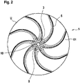
- FIG. 2 shows a plan view of the first top 01 of the upper shell.
- the transport ribs extending from the first upper side 01 can be seen, which initially run in a radial direction from the opening 3 and then bend towards the peripheral edge U in a tangential direction.
- the insert 9 with the air distribution openings 10 downstream of the opening 3 can also be seen.
- FIG. 3 shows a bottom view according to 2 .
- the transport ribs 6 in the form of depressions can be seen on a first underside U1 of the upper shell 5 .
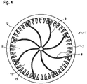
- FIG. 4 shows a plan view of the second upper side 02 of the lower shell 7.
- the lower shell 7 is closed in its center, ie opposite the opening 3 provided in the upper shell 5.
- the walls 8 extend from the second upper side 02.
- the walls 8 run—similar to the transport ribs 6—first in a radial direction from the center and then bend in an essentially tangential direction toward the peripheral edge U.
- the holding devices 13 serve - as in particular with the one explained below figure 5 can be seen - the accommodation and attachment of the shear ribs 12.
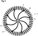
- figure 5 shows a bottom view according to 4 .
- the walls 8 in the form of indentations can be seen on a second underside U2 of the lower shell.
- the holding devices 13, on the other hand, extend from the second underside U2. In this respect, it is also referred to 1 referred.
- An air outlet opening 14 is provided in each case between two adjacent holding devices 13 or two adjacent shearing ribs 12 .
- FIG. 6 shows a schematic sectional view through a transmission 16, which is drivingly connected to a motor 15.
- the gear 16 has a hollow gear shaft 17 whose first end is connected to an air supply line 18 .
- a fan connected to the air supply line 18 is not shown here.
- a second end E2 of the hollow gear shaft 17 is connected to the hollow agitator shaft 1 . How out 1 can be seen, a third end E3 of the hollow agitator shaft 1 with the in Figures 1 to 5 connected to the hyperboloid mixing body shown.
- the particular from the 1 and 6 The resulting stirring and gassing device can, for example, be attached to a raft 19 (see 6 ) to be appropriate.
- a body of water for example a pond, lake or the like, can thus be efficiently circulated and gassed.
Landscapes
- Chemical & Material Sciences (AREA)
- Chemical Kinetics & Catalysis (AREA)
- Engineering & Computer Science (AREA)
- Water Supply & Treatment (AREA)
- Hydrology & Water Resources (AREA)
- Environmental & Geological Engineering (AREA)
- Life Sciences & Earth Sciences (AREA)
- Organic Chemistry (AREA)
- Mixers Of The Rotary Stirring Type (AREA)
- Aeration Devices For Treatment Of Activated Polluted Sludge (AREA)
- Apparatus Associated With Microorganisms And Enzymes (AREA)
- Composite Materials (AREA)
- Mechanical Engineering (AREA)
- Water Treatment By Sorption (AREA)
Applications Claiming Priority (3)
| Application Number | Priority Date | Filing Date | Title |
|---|---|---|---|
| DE202018106871 | 2018-12-03 | ||
| DE102019101416.6A DE102019101416B4 (de) | 2018-12-03 | 2019-01-21 | Hyperboloid-Rührkörper zum Umwälzen von Flüssigkeiten sowie Rühr- und Begasungseinrichtung |
| PCT/EP2019/083096 WO2020114907A1 (de) | 2018-12-03 | 2019-11-29 | Hyperboloid-rührkörper zum umwälzen von flüssigkeiten sowie rühr- und begasungseinrichtung |
Publications (2)
| Publication Number | Publication Date |
|---|---|
| EP3849694A1 EP3849694A1 (de) | 2021-07-21 |
| EP3849694B1 true EP3849694B1 (de) | 2022-07-13 |
Family
ID=69412837
Family Applications (2)
| Application Number | Title | Priority Date | Filing Date |
|---|---|---|---|
| EP19813479.3A Active EP3849694B1 (de) | 2018-12-03 | 2019-11-29 | Hyperboloid-rührkörper zum umwälzen von flüssigkeiten sowie rühr- und begasungseinrichtung |
| EP19813480.1A Active EP3823743B1 (de) | 2018-12-03 | 2019-11-29 | Vorrichtung zum belüften von gewässern |
Family Applications After (1)
| Application Number | Title | Priority Date | Filing Date |
|---|---|---|---|
| EP19813480.1A Active EP3823743B1 (de) | 2018-12-03 | 2019-11-29 | Vorrichtung zum belüften von gewässern |
Country Status (17)
| Country | Link |
|---|---|
| US (2) | US11484848B2 (enExample) |
| EP (2) | EP3849694B1 (enExample) |
| JP (2) | JP7520009B2 (enExample) |
| KR (2) | KR102771242B1 (enExample) |
| CN (2) | CN113490544B (enExample) |
| BR (1) | BR112021006550A2 (enExample) |
| CA (2) | CA3114834A1 (enExample) |
| DE (2) | DE102019101416B4 (enExample) |
| DK (2) | DK3849694T3 (enExample) |
| ES (2) | ES2928354T3 (enExample) |
| HU (2) | HUE060200T2 (enExample) |
| IL (2) | IL281692B2 (enExample) |
| MX (2) | MX2021003937A (enExample) |
| PL (2) | PL3849694T3 (enExample) |
| TW (2) | TWI831876B (enExample) |
| WO (2) | WO2020114907A1 (enExample) |
| ZA (1) | ZA202101963B (enExample) |
Families Citing this family (6)
| Publication number | Priority date | Publication date | Assignee | Title |
|---|---|---|---|---|
| DE102019101416B4 (de) * | 2018-12-03 | 2020-07-16 | Invent Umwelt- Und Verfahrenstechnik Ag | Hyperboloid-Rührkörper zum Umwälzen von Flüssigkeiten sowie Rühr- und Begasungseinrichtung |
| CN111389299A (zh) * | 2020-04-23 | 2020-07-10 | 西安煤科动力科技有限公司 | 一种压滤煤泥分散式制浆机 |
| CN113478864B (zh) * | 2021-07-02 | 2022-03-11 | 南京科技职业学院 | 一种双曲面叶轮的制作方法 |
| KR102623018B1 (ko) * | 2022-06-19 | 2024-01-10 | 황희두 | 수처리용 멀티 구동 교반기 |
| KR102734019B1 (ko) * | 2022-12-12 | 2024-11-25 | 안성만 | 전동공구 연결형 교반기구 |
| CN115849582B (zh) * | 2022-12-13 | 2023-07-07 | 浙江长城搅拌设备股份有限公司 | 一种污水处理用搅拌曝气装置 |
Family Cites Families (46)
| Publication number | Priority date | Publication date | Assignee | Title |
|---|---|---|---|---|
| DE8016582U1 (de) * | 1981-02-05 | Ostermaier, Josef, 8251 Wielerstett | Vorrichtung zum Aufbereiten von Gülle | |
| US1526596A (en) * | 1922-06-09 | 1925-02-17 | William E Greenawalt | Apparatus for treating liquids with gases |
| US1726125A (en) * | 1927-06-23 | 1929-08-27 | Rowand Thomas Arthur | Agitator aerator for liquids |
| GB526692A (en) * | 1939-03-22 | 1940-09-24 | Stanley Tucker | Improvements in or relating to agitation and aeration apparatus |
| CH439139A (de) * | 1965-11-11 | 1967-06-30 | Kaelin J R | Einrichtung zum Umwälzen und Belüften von Flüssigkeiten, insbesondere Gewässer und Abwasser, in einem Becken |
| JPS526954Y1 (enExample) * | 1968-02-10 | 1977-02-14 | ||
| JPS526955Y1 (enExample) * | 1968-03-06 | 1977-02-14 | ||
| US3490996A (en) * | 1968-04-10 | 1970-01-20 | Herbert C Kelly Jr | Solar heated water vapor lifting and condensing system |
| US3630498A (en) * | 1968-07-31 | 1971-12-28 | Namco Corp | Apparatus for gasifying and degasifying a liquid |
| JPS4738472Y1 (enExample) * | 1969-12-24 | 1972-11-21 | ||
| US3782702A (en) * | 1969-12-29 | 1974-01-01 | R King | Apparatus for mixing and treating fluids |
| US3744765A (en) * | 1971-10-28 | 1973-07-10 | M Bard | Turbine mixer |
| JPS5428855Y2 (enExample) * | 1973-05-28 | 1979-09-14 | ||
| JPS57157385A (en) * | 1981-03-25 | 1982-09-28 | Fujitsu Ltd | Variable density picture dot pattern generating device |
| CA1206865A (en) * | 1981-04-13 | 1986-07-02 | Evan E. Koslow | Energy efficient phase transfer/dispersion systems and methods for using the same |
| DE3209283A1 (de) * | 1982-03-13 | 1983-09-22 | Jürgen Dipl.-Ing. 4350 Recklinghausen Enning | Vorrichtung zur hypolimnion-belueftung |
| JPH0768590B2 (ja) * | 1988-10-21 | 1995-07-26 | 昭和アルミニウム株式会社 | 液体中への気泡放出、分散装置 |
| US5013490A (en) * | 1988-10-21 | 1991-05-07 | Showa Aluminum Corporation | Device for releasing and diffusing bubbles into liquid |
| US5255071A (en) * | 1989-09-13 | 1993-10-19 | Pollak Fred H | Photoreflectance method and apparatus utilizing acousto-optic modulation |
| DE19823839A1 (de) | 1998-05-29 | 1999-12-09 | Franz Durst | Verfahren und Vorrichtung zum Mischen und Dispergieren mindestens zweier Phasen |
| DE19826098C2 (de) * | 1998-06-12 | 2002-03-14 | Franz Durst | Rührvorrichtung |
| DE20207376U1 (de) | 2002-05-10 | 2003-06-26 | Invent Umwelt Und Verfahrenste | Rühr- und Begasungsvorrichtung für Belebtschlämme |
| FR2848472B1 (fr) * | 2002-12-12 | 2005-02-18 | Air Liquide | Dispositif d'agitation d'un liquide et d'injection d'un gaz dans ce liquide a engorgement limite |
| US6808165B1 (en) * | 2003-04-30 | 2004-10-26 | Smith & Loveless, Inc. | Apparatus for mixing and introducing gas into a large body of liquid |
| ITVE20040015A1 (it) * | 2004-04-22 | 2004-07-22 | Hydor Srl | Aeratore rotante per acquari |
| DE102005016948B3 (de) * | 2005-04-12 | 2007-01-04 | Invent Umwelt-Und Verfahrenstechnik Ag | Rührvorrichtung und Verfahren zur Abwasserbehandlung |
| CN101555067B (zh) * | 2008-04-09 | 2010-12-29 | 孙树林 | 回转潜浮式曝气机 |
| WO2009018873A1 (de) * | 2007-08-09 | 2009-02-12 | Invent Umwelt-Und Verfahrenstechnik Ag | Rührvorrichtung für belebtschlämme |
| DE102007037586B3 (de) * | 2007-08-09 | 2008-09-18 | Invent Umwelt- Und Verfahrenstechnik Ag | Rührvorrichtung für Belebtschlämme |
| CN101778665B (zh) * | 2007-08-09 | 2013-01-16 | 英文特环境及工艺股份公司 | 用于活性污泥的搅拌设备 |
| CA2607886A1 (en) * | 2007-10-25 | 2009-04-25 | Midan Industries Ltd. | Submersible mixing propeller |
| US7997788B2 (en) * | 2007-10-25 | 2011-08-16 | Midan Industries Ltd. | Submersible mixing propeller |
| KR200447286Y1 (ko) * | 2008-11-24 | 2010-01-14 | 주식회사 수환경알앤디 | 교반기 |
| CN201411391Y (zh) * | 2009-03-24 | 2010-02-24 | 何祖汉 | 具有双层叶轮的曝气搅拌装置 |
| DE102010000730B4 (de) * | 2010-01-07 | 2011-12-15 | Invent Umwelt- Und Verfahrenstechnik Ag | Vertikalrührwerk für in einem Klärbecken aufgenommenes Abwasser |
| CN202430063U (zh) * | 2011-12-21 | 2012-09-12 | 南京蓝深制泵集团股份有限公司 | 一种双曲面搅拌曝气机 |
| CN102491545B (zh) | 2011-12-21 | 2013-09-25 | 南京蓝深制泵集团股份有限公司 | 一种双曲面搅拌曝气机 |
| KR101378181B1 (ko) * | 2013-11-01 | 2014-03-24 | 정욱도 | 분산기 |
| DE102013225662A1 (de) * | 2013-12-11 | 2015-06-11 | Invent Umwelt- Und Verfahrenstechnik Ag | Rührkörper zum Umwälzen von in einem Becken aufgenommenem Abwasser und Vorrichtung |
| DE102013225659A1 (de) * | 2013-12-11 | 2015-06-11 | Invent Umwelt- Und Verfahrenstechnik Ag | Vorrichtung zum Umwälzen einer in einem Behälter aufgenommenen Flüssigkeit |
| CN104326581A (zh) * | 2014-11-18 | 2015-02-04 | 四川邮科通信技术有限公司 | 一种用于电缆生产污水处理的高效节能搅拌曝气机 |
| CN106145400B (zh) * | 2015-04-21 | 2019-05-24 | 崔汇文 | 增氧机 |
| TWM510611U (zh) * | 2015-04-21 | 2015-10-21 | Huei-Wern Tsuei | 增氧機 |
| CN105363374B (zh) * | 2015-11-18 | 2017-08-25 | 亚太水处理(天长)有限公司 | 一种污水搅拌器 |
| AU2017231596A1 (en) * | 2016-03-10 | 2018-11-01 | Bruce Hyndman Henley | Improvements in and relating to mixers |
| DE102019101416B4 (de) | 2018-12-03 | 2020-07-16 | Invent Umwelt- Und Verfahrenstechnik Ag | Hyperboloid-Rührkörper zum Umwälzen von Flüssigkeiten sowie Rühr- und Begasungseinrichtung |
-
2019
- 2019-01-21 DE DE102019101416.6A patent/DE102019101416B4/de active Active
- 2019-02-11 DE DE102019103252.0A patent/DE102019103252B3/de active Active
- 2019-11-26 TW TW108143026A patent/TWI831876B/zh active
- 2019-11-29 CA CA3114834A patent/CA3114834A1/en active Pending
- 2019-11-29 WO PCT/EP2019/083096 patent/WO2020114907A1/de not_active Ceased
- 2019-11-29 ES ES19813479T patent/ES2928354T3/es active Active
- 2019-11-29 IL IL281692A patent/IL281692B2/en unknown
- 2019-11-29 WO PCT/EP2019/083097 patent/WO2020114908A1/de not_active Ceased
- 2019-11-29 EP EP19813479.3A patent/EP3849694B1/de active Active
- 2019-11-29 CA CA3110663A patent/CA3110663A1/en active Pending
- 2019-11-29 HU HUE19813479A patent/HUE060200T2/hu unknown
- 2019-11-29 JP JP2021531642A patent/JP7520009B2/ja active Active
- 2019-11-29 KR KR1020217016631A patent/KR102771242B1/ko active Active
- 2019-11-29 BR BR112021006550A patent/BR112021006550A2/pt active IP Right Grant
- 2019-11-29 MX MX2021003937A patent/MX2021003937A/es unknown
- 2019-11-29 HU HUE19813480A patent/HUE059117T2/hu unknown
- 2019-11-29 CN CN201980061526.1A patent/CN113490544B/zh active Active
- 2019-11-29 CN CN201980064529.0A patent/CN113423490B/zh active Active
- 2019-11-29 DK DK19813479.3T patent/DK3849694T3/da active
- 2019-11-29 US US17/271,723 patent/US11484848B2/en active Active
- 2019-11-29 KR KR1020217013398A patent/KR102715884B1/ko active Active
- 2019-11-29 JP JP2021531643A patent/JP7478735B2/ja active Active
- 2019-11-29 ES ES19813480T patent/ES2920488T3/es active Active
- 2019-11-29 MX MX2021002929A patent/MX2021002929A/es unknown
- 2019-11-29 US US17/279,356 patent/US11731090B2/en active Active
- 2019-11-29 PL PL19813479.3T patent/PL3849694T3/pl unknown
- 2019-11-29 PL PL19813480.1T patent/PL3823743T3/pl unknown
- 2019-11-29 DK DK19813480.1T patent/DK3823743T3/da active
- 2019-11-29 IL IL280976A patent/IL280976B2/en unknown
- 2019-11-29 EP EP19813480.1A patent/EP3823743B1/de active Active
- 2019-12-02 TW TW108143985A patent/TWI832932B/zh active
-
2021
- 2021-03-24 ZA ZA2021/01963A patent/ZA202101963B/en unknown
Also Published As
Similar Documents
| Publication | Publication Date | Title |
|---|---|---|
| EP3849694B1 (de) | Hyperboloid-rührkörper zum umwälzen von flüssigkeiten sowie rühr- und begasungseinrichtung | |
| EP2175972B1 (de) | Rührvorrichtung für belebtschlämme | |
| EP3079801B1 (de) | Rührkörper zum umwälzen von in einem becken aufgenommenem abwasser und vorrichtung | |
| EP2613871B1 (de) | Rührwerk | |
| DE2527790A1 (de) | Absetzvorrichtung fuer eine klaeranlage | |
| EP1868710B1 (de) | Rührvorrichtung und verfahren zur abwasserbehandlung | |
| DE102017114889B4 (de) | Entlüftungssystem für ein Getriebe | |
| DE1265137B (de) | Ruehrwerk zum Belueften von Fluessigkeiten | |
| EP3065852A1 (de) | Rührwerk zum mischen von fluiden | |
| DE102012023271B4 (de) | Mischbehälter | |
| CH690835A5 (de) | Rührwerk zum Anregen einer Güllen-Zirkulation in einem Güllenkasten. | |
| DE69302338T2 (de) | Belüftungsvorrichtung | |
| EP3837040B1 (de) | Propeller und rührwerk zum umwälzen von abwasser in einem klärbecken | |
| DE102004036634B4 (de) | Vorrichtung zum Begasen von Flüssigkeiten und Verfahren zur Montage der Vorrichtung | |
| DE102017221138B4 (de) | Rührgefäß für einen Stabmixer, Einsatzelement für ein Rührgefäß und Küchenrührvorrichtung | |
| DE202007018380U1 (de) | Abschäumer für Aquarien zur Abscheidung von Fest- und/oder Schwebstoffen aus Aquariumwasser | |
| DE2417536A1 (de) | Geraet zum zumischen eines gasfoermigen und/oder eines fluessigen stoffes in ein anderes stroemungsfaehiges medium | |
| EP0147367A2 (de) | Abwasserbelüftungssystem, Verfahren zum Betrieb und Verwendung desselben | |
| DE3419863C2 (de) | Vorrichtung zur Belüftung von Gülle oder dergleichen | |
| DE4315700A1 (de) | Belüftungseinrichtung | |
| DE202014005974U1 (de) | Rührwerk | |
| DE3208462A1 (de) | Vorrichtung zum mischen von massen | |
| DE3344671C2 (de) | Verfahren und Vorrichtung zum Aufbereiten einer Flüssigkeit insbesondere von Gülle | |
| EP1203893B1 (de) | Vorrichtung zum Homogenisieren von Gülle | |
| DE29819704U1 (de) | Begasungsvorrichtung für Flüssigkeiten |
Legal Events
| Date | Code | Title | Description |
|---|---|---|---|
| STAA | Information on the status of an ep patent application or granted ep patent |
Free format text: STATUS: UNKNOWN |
|
| STAA | Information on the status of an ep patent application or granted ep patent |
Free format text: STATUS: THE INTERNATIONAL PUBLICATION HAS BEEN MADE |
|
| PUAI | Public reference made under article 153(3) epc to a published international application that has entered the european phase |
Free format text: ORIGINAL CODE: 0009012 |
|
| STAA | Information on the status of an ep patent application or granted ep patent |
Free format text: STATUS: REQUEST FOR EXAMINATION WAS MADE |
|
| 17P | Request for examination filed |
Effective date: 20210414 |
|
| AK | Designated contracting states |
Kind code of ref document: A1 Designated state(s): AL AT BE BG CH CY CZ DE DK EE ES FI FR GB GR HR HU IE IS IT LI LT LU LV MC MK MT NL NO PL PT RO RS SE SI SK SM TR |
|
| DAV | Request for validation of the european patent (deleted) | ||
| DAX | Request for extension of the european patent (deleted) | ||
| REG | Reference to a national code |
Ref country code: DE Ref legal event code: R079 Ref document number: 502019004974 Country of ref document: DE Free format text: PREVIOUS MAIN CLASS: B01F0003040000 Ipc: B01F0023233000 |
|
| GRAP | Despatch of communication of intention to grant a patent |
Free format text: ORIGINAL CODE: EPIDOSNIGR1 |
|
| STAA | Information on the status of an ep patent application or granted ep patent |
Free format text: STATUS: GRANT OF PATENT IS INTENDED |
|
| RIC1 | Information provided on ipc code assigned before grant |
Ipc: B01F 101/00 20220101ALI20220314BHEP Ipc: C02F 7/00 20060101ALI20220314BHEP Ipc: B01F 33/503 20220101ALI20220314BHEP Ipc: B01F 27/94 20220101ALI20220314BHEP Ipc: B01F 27/80 20220101ALI20220314BHEP Ipc: B01F 27/172 20220101ALI20220314BHEP Ipc: B01F 27/117 20220101ALI20220314BHEP Ipc: B01F 23/233 20220101AFI20220314BHEP |
|
| INTG | Intention to grant announced |
Effective date: 20220331 |
|
| GRAS | Grant fee paid |
Free format text: ORIGINAL CODE: EPIDOSNIGR3 |
|
| GRAA | (expected) grant |
Free format text: ORIGINAL CODE: 0009210 |
|
| STAA | Information on the status of an ep patent application or granted ep patent |
Free format text: STATUS: THE PATENT HAS BEEN GRANTED |
|
| AK | Designated contracting states |
Kind code of ref document: B1 Designated state(s): AL AT BE BG CH CY CZ DE DK EE ES FI FR GB GR HR HU IE IS IT LI LT LU LV MC MK MT NL NO PL PT RO RS SE SI SK SM TR |
|
| REG | Reference to a national code |
Ref country code: CH Ref legal event code: EP |
|
| REG | Reference to a national code |
Ref country code: DE Ref legal event code: R096 Ref document number: 502019004974 Country of ref document: DE |
|
| REG | Reference to a national code |
Ref country code: AT Ref legal event code: REF Ref document number: 1503970 Country of ref document: AT Kind code of ref document: T Effective date: 20220815 |
|
| REG | Reference to a national code |
Ref country code: IE Ref legal event code: FG4D Free format text: LANGUAGE OF EP DOCUMENT: GERMAN |
|
| REG | Reference to a national code |
Ref country code: FI Ref legal event code: FGE |
|
| REG | Reference to a national code |
Ref country code: SE Ref legal event code: TRGR |
|
| REG | Reference to a national code |
Ref country code: DK Ref legal event code: T3 Effective date: 20221011 |
|
| REG | Reference to a national code |
Ref country code: NL Ref legal event code: FP |
|
| REG | Reference to a national code |
Ref country code: LT Ref legal event code: MG9D |
|
| REG | Reference to a national code |
Ref country code: ES Ref legal event code: FG2A Ref document number: 2928354 Country of ref document: ES Kind code of ref document: T3 Effective date: 20221117 |
|
| PG25 | Lapsed in a contracting state [announced via postgrant information from national office to epo] |
Ref country code: RS Free format text: LAPSE BECAUSE OF FAILURE TO SUBMIT A TRANSLATION OF THE DESCRIPTION OR TO PAY THE FEE WITHIN THE PRESCRIBED TIME-LIMIT Effective date: 20220713 Ref country code: PT Free format text: LAPSE BECAUSE OF FAILURE TO SUBMIT A TRANSLATION OF THE DESCRIPTION OR TO PAY THE FEE WITHIN THE PRESCRIBED TIME-LIMIT Effective date: 20221114 Ref country code: NO Free format text: LAPSE BECAUSE OF FAILURE TO SUBMIT A TRANSLATION OF THE DESCRIPTION OR TO PAY THE FEE WITHIN THE PRESCRIBED TIME-LIMIT Effective date: 20221013 Ref country code: LV Free format text: LAPSE BECAUSE OF FAILURE TO SUBMIT A TRANSLATION OF THE DESCRIPTION OR TO PAY THE FEE WITHIN THE PRESCRIBED TIME-LIMIT Effective date: 20220713 Ref country code: LT Free format text: LAPSE BECAUSE OF FAILURE TO SUBMIT A TRANSLATION OF THE DESCRIPTION OR TO PAY THE FEE WITHIN THE PRESCRIBED TIME-LIMIT Effective date: 20220713 |
|
| PG25 | Lapsed in a contracting state [announced via postgrant information from national office to epo] |
Ref country code: IS Free format text: LAPSE BECAUSE OF FAILURE TO SUBMIT A TRANSLATION OF THE DESCRIPTION OR TO PAY THE FEE WITHIN THE PRESCRIBED TIME-LIMIT Effective date: 20221113 Ref country code: HR Free format text: LAPSE BECAUSE OF FAILURE TO SUBMIT A TRANSLATION OF THE DESCRIPTION OR TO PAY THE FEE WITHIN THE PRESCRIBED TIME-LIMIT Effective date: 20220713 Ref country code: GR Free format text: LAPSE BECAUSE OF FAILURE TO SUBMIT A TRANSLATION OF THE DESCRIPTION OR TO PAY THE FEE WITHIN THE PRESCRIBED TIME-LIMIT Effective date: 20221014 |
|
| REG | Reference to a national code |
Ref country code: HU Ref legal event code: AG4A Ref document number: E060200 Country of ref document: HU |
|
| REG | Reference to a national code |
Ref country code: DE Ref legal event code: R097 Ref document number: 502019004974 Country of ref document: DE |
|
| PG25 | Lapsed in a contracting state [announced via postgrant information from national office to epo] |
Ref country code: SM Free format text: LAPSE BECAUSE OF FAILURE TO SUBMIT A TRANSLATION OF THE DESCRIPTION OR TO PAY THE FEE WITHIN THE PRESCRIBED TIME-LIMIT Effective date: 20220713 Ref country code: RO Free format text: LAPSE BECAUSE OF FAILURE TO SUBMIT A TRANSLATION OF THE DESCRIPTION OR TO PAY THE FEE WITHIN THE PRESCRIBED TIME-LIMIT Effective date: 20220713 |
|
| PLBE | No opposition filed within time limit |
Free format text: ORIGINAL CODE: 0009261 |
|
| STAA | Information on the status of an ep patent application or granted ep patent |
Free format text: STATUS: NO OPPOSITION FILED WITHIN TIME LIMIT |
|
| PG25 | Lapsed in a contracting state [announced via postgrant information from national office to epo] |
Ref country code: SK Free format text: LAPSE BECAUSE OF FAILURE TO SUBMIT A TRANSLATION OF THE DESCRIPTION OR TO PAY THE FEE WITHIN THE PRESCRIBED TIME-LIMIT Effective date: 20220713 Ref country code: EE Free format text: LAPSE BECAUSE OF FAILURE TO SUBMIT A TRANSLATION OF THE DESCRIPTION OR TO PAY THE FEE WITHIN THE PRESCRIBED TIME-LIMIT Effective date: 20220713 |
|
| 26N | No opposition filed |
Effective date: 20230414 |
|
| PG25 | Lapsed in a contracting state [announced via postgrant information from national office to epo] |
Ref country code: MC Free format text: LAPSE BECAUSE OF FAILURE TO SUBMIT A TRANSLATION OF THE DESCRIPTION OR TO PAY THE FEE WITHIN THE PRESCRIBED TIME-LIMIT Effective date: 20220713 Ref country code: AL Free format text: LAPSE BECAUSE OF FAILURE TO SUBMIT A TRANSLATION OF THE DESCRIPTION OR TO PAY THE FEE WITHIN THE PRESCRIBED TIME-LIMIT Effective date: 20220713 |
|
| PG25 | Lapsed in a contracting state [announced via postgrant information from national office to epo] |
Ref country code: SI Free format text: LAPSE BECAUSE OF FAILURE TO SUBMIT A TRANSLATION OF THE DESCRIPTION OR TO PAY THE FEE WITHIN THE PRESCRIBED TIME-LIMIT Effective date: 20220713 Ref country code: LU Free format text: LAPSE BECAUSE OF NON-PAYMENT OF DUE FEES Effective date: 20221129 |
|
| PG25 | Lapsed in a contracting state [announced via postgrant information from national office to epo] |
Ref country code: CY Free format text: LAPSE BECAUSE OF FAILURE TO SUBMIT A TRANSLATION OF THE DESCRIPTION OR TO PAY THE FEE WITHIN THE PRESCRIBED TIME-LIMIT Effective date: 20220713 |
|
| PG25 | Lapsed in a contracting state [announced via postgrant information from national office to epo] |
Ref country code: MK Free format text: LAPSE BECAUSE OF FAILURE TO SUBMIT A TRANSLATION OF THE DESCRIPTION OR TO PAY THE FEE WITHIN THE PRESCRIBED TIME-LIMIT Effective date: 20220713 |
|
| PG25 | Lapsed in a contracting state [announced via postgrant information from national office to epo] |
Ref country code: BG Free format text: LAPSE BECAUSE OF FAILURE TO SUBMIT A TRANSLATION OF THE DESCRIPTION OR TO PAY THE FEE WITHIN THE PRESCRIBED TIME-LIMIT Effective date: 20220713 |
|
| PG25 | Lapsed in a contracting state [announced via postgrant information from national office to epo] |
Ref country code: MT Free format text: LAPSE BECAUSE OF FAILURE TO SUBMIT A TRANSLATION OF THE DESCRIPTION OR TO PAY THE FEE WITHIN THE PRESCRIBED TIME-LIMIT Effective date: 20220713 |
|
| REG | Reference to a national code |
Ref country code: CH Ref legal event code: U11 Free format text: ST27 STATUS EVENT CODE: U-0-0-U10-U11 (AS PROVIDED BY THE NATIONAL OFFICE) Effective date: 20251201 |
|
| PG25 | Lapsed in a contracting state [announced via postgrant information from national office to epo] |
Ref country code: TR Free format text: LAPSE BECAUSE OF FAILURE TO SUBMIT A TRANSLATION OF THE DESCRIPTION OR TO PAY THE FEE WITHIN THE PRESCRIBED TIME-LIMIT Effective date: 20220713 |
|
| PGFP | Annual fee paid to national office [announced via postgrant information from national office to epo] |
Ref country code: HU Payment date: 20251127 Year of fee payment: 7 |
|
| PGFP | Annual fee paid to national office [announced via postgrant information from national office to epo] |
Ref country code: NL Payment date: 20251119 Year of fee payment: 7 |
|
| PGFP | Annual fee paid to national office [announced via postgrant information from national office to epo] |
Ref country code: DE Payment date: 20251118 Year of fee payment: 7 |
|
| PGFP | Annual fee paid to national office [announced via postgrant information from national office to epo] |
Ref country code: GB Payment date: 20251120 Year of fee payment: 7 |
|
| PGFP | Annual fee paid to national office [announced via postgrant information from national office to epo] |
Ref country code: AT Payment date: 20251117 Year of fee payment: 7 |
|
| PGFP | Annual fee paid to national office [announced via postgrant information from national office to epo] |
Ref country code: IT Payment date: 20251128 Year of fee payment: 7 Ref country code: FI Payment date: 20251118 Year of fee payment: 7 Ref country code: DK Payment date: 20251119 Year of fee payment: 7 |
|
| PGFP | Annual fee paid to national office [announced via postgrant information from national office to epo] |
Ref country code: FR Payment date: 20251125 Year of fee payment: 7 |
|
| PGFP | Annual fee paid to national office [announced via postgrant information from national office to epo] |
Ref country code: BE Payment date: 20251118 Year of fee payment: 7 |
|
| PGFP | Annual fee paid to national office [announced via postgrant information from national office to epo] |
Ref country code: CH Payment date: 20251201 Year of fee payment: 7 Ref country code: SE Payment date: 20251119 Year of fee payment: 7 |
|
| PGFP | Annual fee paid to national office [announced via postgrant information from national office to epo] |
Ref country code: IE Payment date: 20251120 Year of fee payment: 7 Ref country code: CZ Payment date: 20251118 Year of fee payment: 7 |
|
| PGFP | Annual fee paid to national office [announced via postgrant information from national office to epo] |
Ref country code: PL Payment date: 20251119 Year of fee payment: 7 |
|
| PGFP | Annual fee paid to national office [announced via postgrant information from national office to epo] |
Ref country code: ES Payment date: 20251216 Year of fee payment: 7 |