EP3848522A1 - Floor drain - Google Patents
Floor drain Download PDFInfo
- Publication number
- EP3848522A1 EP3848522A1 EP20157750.9A EP20157750A EP3848522A1 EP 3848522 A1 EP3848522 A1 EP 3848522A1 EP 20157750 A EP20157750 A EP 20157750A EP 3848522 A1 EP3848522 A1 EP 3848522A1
- Authority
- EP
- European Patent Office
- Prior art keywords
- floor drain
- connecting part
- fastening sleeve
- sealing
- flexible element
- Prior art date
- Legal status (The legal status is an assumption and is not a legal conclusion. Google has not performed a legal analysis and makes no representation as to the accuracy of the status listed.)
- Pending
Links
- 238000007789 sealing Methods 0.000 claims abstract description 71
- 239000000463 material Substances 0.000 claims abstract description 12
- 239000004033 plastic Substances 0.000 claims description 18
- 229920003023 plastic Polymers 0.000 claims description 18
- 239000002131 composite material Substances 0.000 claims description 12
- 239000013013 elastic material Substances 0.000 claims description 7
- 229920001971 elastomer Polymers 0.000 claims description 7
- 239000000806 elastomer Substances 0.000 claims description 7
- -1 polypropylene Polymers 0.000 claims description 6
- 229930040373 Paraformaldehyde Natural products 0.000 claims description 3
- 239000004952 Polyamide Substances 0.000 claims description 3
- 239000004743 Polypropylene Substances 0.000 claims description 3
- XECAHXYUAAWDEL-UHFFFAOYSA-N acrylonitrile butadiene styrene Chemical compound C=CC=C.C=CC#N.C=CC1=CC=CC=C1 XECAHXYUAAWDEL-UHFFFAOYSA-N 0.000 claims description 3
- 229920000122 acrylonitrile butadiene styrene Polymers 0.000 claims description 3
- 239000004676 acrylonitrile butadiene styrene Substances 0.000 claims description 3
- 239000011324 bead Substances 0.000 claims description 3
- 229920002647 polyamide Polymers 0.000 claims description 3
- 229920006324 polyoxymethylene Polymers 0.000 claims description 3
- 229920001155 polypropylene Polymers 0.000 claims description 3
- 229920002725 thermoplastic elastomer Polymers 0.000 claims description 3
- 238000009434 installation Methods 0.000 description 6
- 238000012423 maintenance Methods 0.000 description 5
- 238000010276 construction Methods 0.000 description 4
- 230000000694 effects Effects 0.000 description 4
- 239000002351 wastewater Substances 0.000 description 4
- 238000004140 cleaning Methods 0.000 description 3
- 150000001875 compounds Chemical class 0.000 description 2
- 238000006073 displacement reaction Methods 0.000 description 2
- 239000002689 soil Substances 0.000 description 2
- 229910000831 Steel Inorganic materials 0.000 description 1
- NIXOWILDQLNWCW-UHFFFAOYSA-N acrylic acid group Chemical group C(C=C)(=O)O NIXOWILDQLNWCW-UHFFFAOYSA-N 0.000 description 1
- 238000004026 adhesive bonding Methods 0.000 description 1
- 230000004323 axial length Effects 0.000 description 1
- 230000015572 biosynthetic process Effects 0.000 description 1
- 238000005266 casting Methods 0.000 description 1
- 210000003298 dental enamel Anatomy 0.000 description 1
- 238000007688 edging Methods 0.000 description 1
- 239000012535 impurity Substances 0.000 description 1
- 229910052500 inorganic mineral Inorganic materials 0.000 description 1
- 239000011707 mineral Substances 0.000 description 1
- 230000035515 penetration Effects 0.000 description 1
- 230000001681 protective effect Effects 0.000 description 1
- 239000010865 sewage Substances 0.000 description 1
- 239000010959 steel Substances 0.000 description 1
- 239000004575 stone Substances 0.000 description 1
Images


Classifications
-
- E—FIXED CONSTRUCTIONS
- E03—WATER SUPPLY; SEWERAGE
- E03F—SEWERS; CESSPOOLS
- E03F5/00—Sewerage structures
- E03F5/04—Gullies inlets, road sinks, floor drains with or without odour seals or sediment traps
- E03F5/0407—Floor drains for indoor use
-
- E—FIXED CONSTRUCTIONS
- E03—WATER SUPPLY; SEWERAGE
- E03F—SEWERS; CESSPOOLS
- E03F5/00—Sewerage structures
- E03F5/04—Gullies inlets, road sinks, floor drains with or without odour seals or sediment traps
- E03F5/0407—Floor drains for indoor use
- E03F5/0408—Floor drains for indoor use specially adapted for showers
-
- E—FIXED CONSTRUCTIONS
- E03—WATER SUPPLY; SEWERAGE
- E03F—SEWERS; CESSPOOLS
- E03F5/00—Sewerage structures
- E03F5/04—Gullies inlets, road sinks, floor drains with or without odour seals or sediment traps
- E03F5/0407—Floor drains for indoor use
- E03F5/0409—Devices for preventing seepage around the floor drain
-
- E—FIXED CONSTRUCTIONS
- E03—WATER SUPPLY; SEWERAGE
- E03F—SEWERS; CESSPOOLS
- E03F5/00—Sewerage structures
- E03F5/04—Gullies inlets, road sinks, floor drains with or without odour seals or sediment traps
- E03F2005/0412—Gullies inlets, road sinks, floor drains with or without odour seals or sediment traps with means for adjusting their position with respect to the surrounding surface
- E03F2005/0413—Gullies inlets, road sinks, floor drains with or without odour seals or sediment traps with means for adjusting their position with respect to the surrounding surface for height adjustment
-
- E—FIXED CONSTRUCTIONS
- E03—WATER SUPPLY; SEWERAGE
- E03F—SEWERS; CESSPOOLS
- E03F5/00—Sewerage structures
- E03F5/04—Gullies inlets, road sinks, floor drains with or without odour seals or sediment traps
- E03F2005/0412—Gullies inlets, road sinks, floor drains with or without odour seals or sediment traps with means for adjusting their position with respect to the surrounding surface
- E03F2005/0415—Gullies inlets, road sinks, floor drains with or without odour seals or sediment traps with means for adjusting their position with respect to the surrounding surface for horizontal position adjustment
Definitions
- the invention comprises a floor drain for the sanitary area, in particular for showers.
- floor plates which can consist of natural stone or mineral casting, for example.
- floor panels which have a slope towards the central opening, for example, can be very heavy and unwieldy. It can be problematic to place such a floor plate in the corner of a room, for example as a shower tray. This is particularly the case when the upper inlet opening of the drain device, which is already partially preinstalled in the floor, is not aligned with the opening in the base plate.
- shower trays made of acrylic or steel enamel which, due to local conditions in the building, cannot always be installed so precisely that their outlet opening is flush with the floor drain that has already been installed in the floor.
- the drain body is installed directly in the floor structure and integrated into the floor seal with a sealing element.
- this type of installation of the drain body has the disadvantage that the drain body cannot be changed in order to compensate for a misalignment of the shower tray.
- the drainage device for arrangement on a base plate with an opening for waste water.
- the drainage device comprises an upper inlet opening into which the waste water can enter, the drainage device comprising parts that can be preassembled in the floor area and being connectable to a drainage pipe so that waste water that has flowed through the inlet opening can enter the drainage pipe.
- the drain device In a partially mounted state in the floor area, the drain device comprises at least two parts that can be moved relative to one another, so that the opening in the base plate can be moved relative to the parts preassembled in the floor area by moving these parts relative to one another.
- this drain device is its complicated assembly. Another disadvantage is that this drain device consists of a large number of individual parts, all of which have to be assembled on the building in the correct order.
- the main disadvantage is the fact that an offset between the opening in the base plate and the drain device can essentially only be compensated in the horizontal plane, whereas an offset in the vertical direction can only be compensated to a very limited extent and with cumbersome assembly steps.
- a drain device for arrangement on a base plate with an opening for sewage.
- the drainage device comprises an upper inlet opening into which waste water can enter, a first part that can be preassembled in the floor area, a second part, the position of which in the assembled state influences the position of the upper inlet opening, and a third part which is installed in a floor area State can be tilted relative to the vertical in such a way that the second part is moved relative to the first part.
- the parts are tubular, the third part being at least partially received in the first part.
- the disadvantage of this floor drain is, on the one hand, that only relatively small deviations from the alignment of the opening in the base plate and the inlet of the drain device can be compensated for.
- a particular disadvantage, however, is the large installation depth in the floor, which this drainage device requires. The required floor height is no longer given in modern residential buildings, especially not for barrier-free showers or showers with very flat shower trays.
- the present invention achieves the set objects by a floor drain mentioned at the beginning with the characterizing features of claim 1.
- Advantageous embodiments of the floor drain according to the invention are set out in the subclaims, the description and the drawings.
- the floor drain according to the invention for the sanitary area comprises a drain body with a connection for a drain pipe and an inlet communicating with the connection, a waterproof, flexible sealing fitting that can be applied to a floor surface and has a sealing collar that can be inserted into the inlet of the drain body, and one that can be inserted into the sealing collar , tubular connecting part with a first and a second open end, and a fastening device fixing the connecting part.
- the sealing sleeve has a flexible element made of a waterproof material with a through hole, which can be detachably connected to the first end of the connecting part or the fastening device, the fastening device being designed as a fastening sleeve with a fastening sleeve body with an open end section and the flexible element being detachable with the fastening sleeve is connectable.
- the fastening device consists of a number of screws which are screwed from above through the shower tray to the connecting element and thus press the connecting element against the shower tray from below.
- such a design is not preferred because it requires the formation and sealing of holes in the shower tray.
- the fastening device has an annular clamping element with through holes and screws, the annular clamping element being placed on the edge of the outlet opening of the shower tray from above, then the screws being passed through the through holes of the clamping element and inserted into threaded holes in the connecting element and tightened , whereby the connecting element is pressed against the underside of the shower tray.
- the design of the fastening device is a fastening sleeve, as will be explained in detail below.
- the floor drain according to the invention enables the parts of the floor drain pre-assembled in the floor to be compensated for in relation to the position of a drain opening of a shower tray or a floor plate both in height and in a horizontal plane, i.e. in all three spatial directions.
- the flexible element is preferably movable in all three spatial directions in such a way that the through hole of the flexible element can be pulled up at least to the upper edge of the sealing collar or beyond.
- the flexible element is made of an elastic material, in particular an elastomer plastic, preferably a thermoplastic elastomer.
- an elastomer plastic preferably a thermoplastic elastomer.
- the flexible element is provided with corrugations or folds. This embodiment makes it possible to even large offsets between equalize the outlet opening of the shower tray or the floor plate and the pre-assembled parts of the floor drain. The compensation possibilities in all directions are further increased if the flexible element has at least one corrugation or fold surrounding the through hole.
- the through hole of the flexible element has a border made of a dimensionally stable material, in particular a dimensionally stable plastic, preferably polypropylene, polyamide, polyoxymethylene or acrylonitrile-butadiene-styrene, which with the first end of the connecting part or the fastening sleeve, preferably by form fit or friction fit, can be tightly connected.
- a dimensionally stable material in particular a dimensionally stable plastic, preferably polypropylene, polyamide, polyoxymethylene or acrylonitrile-butadiene-styrene, which with the first end of the connecting part or the fastening sleeve, preferably by form fit or friction fit, can be tightly connected.
- the enclosure has a U-shaped cross section with two legs and a deflection section connecting the two legs, with the wall section of the connecting part defining the first end or the open end section of the fastening sleeve body of the fastening sleeve being insertable between the two legs in a sealing manner .
- This embodiment offers a precise, easily produced and releasable connection between the flexible element and the connecting part.
- a releasable connection between the flexible element and the connecting part is essential for maintenance work, for example to check the tightness of the drainage system. If the outside of the deflection section of the enclosure is rounded, a cleaning spring can be inserted through the floor drain into the drainage pipe and withdrawn again without interference and without damaging the flexible element.
- the first end of the connecting part is provided with a circumferential seal, in particular an O-ring, or a circumferential bead made of a flexible, watertight material, or the first end of the connecting part has an end-face groove into which the the wall of the flexible element defining the through hole can be used.
- the enclosure and the flexible element are designed as a composite injection-molded part.
- the sealing collar and the flexible element can also be designed as a composite injection-molded part.
- the sealing fitting has a waterproof flat element, preferably a plastic fleece, which surrounds the sealing collar and sealingly connected to the sealing collar is.
- the connecting part is provided with a flange at its second end.
- the connecting part is guided with its first end first through the outlet opening of the shower tray from above until the flange of the second end of the connecting part rests on the edge of the outlet opening of the shower tray.
- the connecting part has an external thread and the fastening sleeve is designed as a screw nut with an internal thread, the internal thread engaging with the external thread of the connecting part.
- the fastening sleeve When the connecting part is inserted into the shower tray, the fastening sleeve is screwed from the underside of the shower tray to the connecting part, whereby the flange of the connecting part is clamped to the shower tray and the fastening sleeve is pressed against the shower tray from the opposite side, whereby the connecting part is sealed in the outlet opening of the shower tray is added.
- the fastening sleeve is provided with a circumferential seal.
- the fastening sleeve preferably has a fastening sleeve body made of a dimensionally stable plastic, the seal consists of an elastomer plastic and the fastening sleeve body and the seal are designed as a composite injection-molded part.
- the fastening sleeve is preferred to design the fastening sleeve as a screw nut which engages around the connecting part and can be screwed to it.
- interlocking locking elements on the fastening sleeve and the connecting part or a frictional connection can also be provided.
- the first end of the connecting part or the open end section of the fastening sleeve body is provided with a circumferential seal, in particular an O-ring or a circumferential bead made of a flexible, waterproof material, or is the first end of the connecting part or the open end section of the fastening sleeve body formed with an end-face groove into which the wall of the flexible element defining the through hole can be inserted.
- An odor trap known per se in particular an odor trap based on the siphon principle, can also be inserted into the connecting part.
- FIG. 1 the components of an embodiment of a floor drain 1 according to the invention explained according to a first embodiment.
- the floor drain 1 has a drain body 10 which has a connection 11 for a drain pipe (not shown).
- the nozzle-shaped connection 11 protrudes laterally from the drain body 10 at a section that is lower in the installed position and ends in a second connection 12 with a larger dimension.
- the hollow drain body 10 has an inlet 13 at its upper end which is defined by an inlet wall 14.
- the inlet 13 and the connections 11 and 12 for the drain pipe communicate with one another.
- the drain body 10 has slot-shaped guide elements 15 on its outside.
- the guide elements 15 are displaceably engaged with sections of assembly elements 20. The positions of the assembly elements 20 in the guide elements 15 can be fixed by means of fixing screws 21.
- the drain body 10 can be mounted in a height-adjustable manner, the mounting elements 20 being mounted beforehand on a floor, for example a raw concrete floor, by means of floor screws 22.
- the height of the inlet 13 can be adjusted by cutting the inlet wall 14 to a suitable height on the construction site, in particular so that it is later flush with the surface of a layer to be produced, for example a screed layer.
- a protective cover known to a person skilled in the art can be used.
- the floor drain 1 further comprises a sealing fitting 30, which has a waterproof flat element 31, preferably a plastic fleece, and a sealing collar 32, the flat waterproof element 31 being connected to the sealing collar 32 in a sealing manner.
- the sealing collar 32 When installing the floor drain 1, the sealing collar 32 is inserted into the inlet 13 of the drain body 10 in a sealing manner. Since the height of the inlet 13 has been appropriately adjusted beforehand by cutting the inlet wall 14 to length, after the sealing sleeve 32 has been inserted into the inlet 13, the flat waterproof element 31 rests on the soil layer, in particular the screed layer, which has been formed in the meantime.
- the flat waterproof element 31 is sealed with a sealing compound between its underside and the surface of the screed layer.
- the two-dimensional watertight element 31 can also be sealed with a sealing compound on its upper side and an overlying layer of a floor covering, e.g. a tile covering.
- a flexible element 40 which will be discussed in detail below, extends from the lower edge of the sealing collar 32.
- the floor drain 1 further comprises a tubular connecting part 50, with a first open, lower end 53 in the installed position, and with a second open, upper end 54 in the installed position.
- a flange 52 extends outward from the second end 54.
- the connecting part 50 has a on its outer wall External thread 51. Furthermore, a fastening sleeve 55 with an internal thread 58 is provided, the internal thread 58 engaging with the external thread 51 of the connecting part 50.
- the outlet opening 101 of the shower tray 100 has a shoulder 102 on which the flange 52 of the connecting part 50 rests in the inserted state.
- the fastening sleeve 55 is screwed from the underside of the shower tray 100 to the connecting part 50, whereby the flange 52 of the connecting part 50 is clamped to the shoulder 102 of the shower tray 100 and the fastening sleeve 55 is pressed against the shower tray 100 from the opposite side, as a result of which the connecting part 50 is accommodated in a sealing manner in the outlet opening 101 of the shower tray 100.
- the fastening sleeve 55 is provided with a circumferential seal 57 on its end face facing the shower tray 100 in the installed state.
- the fastening sleeve 55 preferably has a fastening sleeve body 56 made of a dimensionally stable plastic, the seal 57 being made of an elastomer plastic and the fastening sleeve body 56 and the seal 57 being formed as a composite injection-molded part.
- a known two-part odor trap 60 which is designed according to the siphon principle, can be inserted into the connecting part 50.
- a cover plate 70 which can be inserted into the second open end 54 of the connecting part 50, covers the interior of the floor drain 1.
- An assembly key 71 makes it easier to screw the connecting part 50 to the fastening sleeve 55.
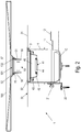
- Fig. 2 shows the floor drain 1 in a state in which the connecting part 50 has already been inserted into the outlet opening 101 of the shower tray 100 and screwed to the fastening sleeve 55. However, the shower tray 100 is not yet in its intended position been placed. Furthermore shows Fig. 2 that the sealing fitting 30 has already been connected to the drain body 10 by inserting the sealing collar 32 into the inlet 13 of the drain body.
- the sealing collar 32 has a flexible element 40 made of a waterproof material.
- the flexible element 40 has a through hole 41, which in this exemplary embodiment is designed as a central through hole 41.
- the flexible element 40 is preferably made from an elastic material, in particular an elastomer plastic, preferably a thermoplastic elastomer.
- the flexible element 40 is provided with two corrugations 42, 43 which allow the through hole 41 to be easily displaced in all three spatial directions, a displacement of several centimeters being possible in each spatial direction.
- the corrugations 42, 43 surround the through hole 41 concentrically.
- the through hole 41 of the flexible element 40 is provided with a border 44 made of a dimensionally stable material, in particular a dimensionally stable plastic, preferably polypropylene, polyamide, polyoxymethylene or acrylonitrile-butadiene-styrene, which with the first end 53 of the connecting part 50 can be connected in a sealing manner by form fit or friction fit.
- a dimensionally stable material in particular a dimensionally stable plastic, preferably polypropylene, polyamide, polyoxymethylene or acrylonitrile-butadiene-styrene, which with the first end 53 of the connecting part 50 can be connected in a sealing manner by form fit or friction fit.
- the enclosure 44 has a U-shaped cross section with two legs 45, 46 and a deflection section 47 connecting the two legs.
- the wall section of the connecting part 50 defining the first end 53 is inserted between the two legs 45, 46 in a sealing manner in the assembled state.
- the inner edge of the elastic material of the elastic element 40 is located between the two legs 45, 46 of the enclosure 44.
- the wall of the first end 53 of the connecting part 50 and the inner edge of the elastic material of the elastic element 40 are designed to undercut one another, as a result of which a certain degree of form fit is achieved.
- One recognizes in detail A of Fig. 3 also that the outside of the deflection section 47 of the enclosure 44 is rounded, which facilitates the introduction of a cleaning spring for maintenance purposes.
- the enclosure 44 and the flexible element 40 are designed as a composite injection-molded part.
- the sealing collar 32 and the flexible element 40 are also designed as a composite injection-molded part.
- the final assembly of the floor drain 1 takes place in that the fitter, after placing the shower tray 100 from the top of the shower tray 100 through the connecting part 50, grips the bezel 44 of the flexible element 40 and pulls it over the lower first end 53 of the connecting part 50, whereby a sealing but releasable Connection between the flexible element 40 and the connecting part 50 is created.
- This connection can be released for maintenance and control purposes by pulling the enclosure 44 downward from the connection part 50. It can then be seen whether the surface of the flexible element 40 is dry, which indicates a correct installation of the floor drain 1. If, however, the surface of the flexible element is damp or even wet, the sealing fitting 30 was probably not installed correctly or damaged during installation, or the shower tray 100 with the fastening sleeve 55 is not connected in a sealing manner.
- Fig. 3 shows the floor drain 1 in a fully assembled state, in which the outlet opening 101 of the shower tray and the inlet 13 of the drain body 10 are arranged coaxially to one another.
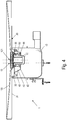
- Fig. 4 shows the floor drain 1 in a fully assembled state, in which the central axis of the outlet opening 101 of the shower tray and the central axis of the inlet 13 of the drain body 10 are axially offset from one another. It can be seen that due to the offset, the left part of the flexible element 40 in the figure is stretched and the right part of the flexible element 40 is compressed so that the enclosure 43 could be connected to the connecting element 50 in a sealing manner.
- the floor drain 1 has a drain body 10 which has a connection 11 for a drain pipe.
- the nozzle-shaped connection 11 protrudes laterally from the drain body 10 at a section that is lower in the installed position and ends in a second connection 12 with a larger dimension.
- the hollow drain body 10 has an inlet 13 at its upper end which is defined by an inlet wall 14.
- the inlet 13 and the connections 11 and 12 for the drain pipe communicate with one another.
- the drain body 10 has slot-shaped guide elements 15 on its outside Guide elements 15 are slidably engaged with sections of assembly elements 20. The positions of assembly elements 20 in guide elements 15 can be fixed by means of fixing screws 21.
- the drain body 10 can be mounted in a height-adjustable manner, the mounting elements 20 being mounted beforehand on a floor, for example a raw concrete floor, by means of floor screws 22.
- the height of the inlet 13 can be adjusted by cutting the inlet wall 14 to a suitable height on the construction site, in particular so that it is later flush with the surface of a layer to be produced, for example a screed layer.
- the floor drain 1 further comprises a sealing fitting 30, which has a waterproof flat element 31, preferably a plastic fleece, and a sealing collar 32, the flat waterproof element 31 being connected to the sealing collar 32 in a sealing manner.
- the sealing collar 32 When installing the floor drain 1, the sealing collar 32 is inserted into the inlet 13 of the drain body 10 in a sealing manner. Since the height of the inlet 13 has been appropriately adjusted beforehand by cutting the inlet wall 14 to length, after the sealing sleeve 32 has been inserted into the inlet 13, the flat waterproof element 31 rests on the soil layer that has been formed in the meantime.
- the floor drain 1 further comprises a tubular connecting part 50, with a first open, lower end 53 in the installed position, and with a second open, upper end 54 in the installed position.
- a flange 52 extends outward from the second end 54.
- the connecting part 50 has an external thread 51 on its outer wall. Furthermore, a fastening sleeve 55 with an internal thread 58 is provided, the internal thread 58 engaging with the external thread 51 of the connecting part 50.
- the outlet opening 101 of the shower tray 100 has a shoulder 102 on which the flange 52 of the connecting part 50 rests in the inserted state.
- the fastening sleeve 55 is screwed from the underside of the shower tray 100 to the connecting part 50, whereby the flange 52 of the connecting part 50 is clamped to the shoulder 102 of the shower tray 100 and the fastening sleeve 55 is pressed from the opposite side against the shower tray 100, whereby the connecting part 50 is sealingly received in the outlet opening 101 of the shower tray 100.
- the fastening sleeve 55 is on Their end face, which faces the shower tray 100 in the installed state, is provided with a circumferential seal 57.
- the fastening sleeve 55 has a fastening sleeve body 56 made of a dimensionally stable plastic, the seal 57 being made of an elastomer plastic and the fastening sleeve body 56 and the seal 57 being designed as a composite injection-molded part.
- a known two-part odor trap 60 can be inserted into the connecting part 50.
- a cover plate 70 which can be inserted into the second open end 54 of the connecting part 50, covers the interior of the floor drain 1.
- An assembly key 71 makes it easier to screw the connecting part 50 to the fastening sleeve 55.
- Figures 6 and 7th Referring to the longitudinal sectional views during the assembly of the floor drain 1 ( Fig. 6 ) or in the assembled state ( Fig. 7 ) demonstrate.
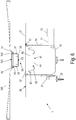
- Fig. 6 shows the floor drain 1 in a state in which the connecting part 50 has already been inserted into the outlet opening 101 of the shower tray 100 and screwed to the fastening sleeve 55. However, the shower tray 100 has not yet been placed in its intended position. Furthermore shows Fig. 6 that the sealing fitting 30 has already been connected to the drain body 10 by inserting the sealing collar 32 into the inlet 13 of the drain body.
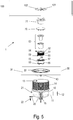
- the fastening sleeve body 56 of the fastening sleeve 55 is cylindrical and has an open end section 59 which faces away from the shower tray 100 in the installed position.
- the axial length of the fastening sleeve 55 is greater than that of the connecting element 50, as a result of which the open end section 59 of the fastening sleeve 55 protrudes from the first open end 53 of the connecting element 50 when the fastening sleeve 55 is screwed to the connecting element 50 .
- the sealing collar 32 has a flexible element 40 made of a waterproof material.
- the flexible element 40 has a through hole 41.
- the flexible element 40 is provided with two corrugations 42, 43, which allow the through hole 41 to be easily displaced in all three spatial directions, a displacement of several centimeters in each spatial direction being possible.
- the corrugations 42, 43 surround the through hole 41 concentrically.
- the through hole 41 of the flexible element 40 is provided with an edging 44 made of a dimensionally stable material, which can be connected in a sealing manner to the open end section 59 of the fastening sleeve 55 by means of a form fit or friction fit.
- the enclosure 44 has a U-shaped cross section with two legs 45, 46 and a deflection section 47 connecting the two legs.
- the wall section of the fastening sleeve body 56 defining the open end section 59 of the fastening sleeve 55 is inserted between the two legs 45, 46 in a sealing manner in the assembled state.
- the inner edge of the elastic material of the elastic element 40 is located between the two legs 45, 46 of the enclosure 44.
- the walls of the open end section 59 of the fastening sleeve 55 and the inner edge of the elastic material of the elastic element 40 are designed to undercut one another, as a result of which a certain degree of form fit is achieved.
- One recognizes in detail B of Fig. 7 also that the outside of the deflection section 47 of the enclosure 44 is rounded, which facilitates the introduction of a cleaning spring for maintenance purposes.
- the enclosure 44 and the flexible element 40 are designed as a composite injection-molded part.
- the sealing collar 32 and the flexible element 40 are also designed as a composite injection-molded part.
- the final assembly of the floor drain 1 takes place in that the fitter, after placing the shower tray 100 from the top of the shower tray 100 through the connecting part 50, grips the surround 44 of the flexible element 40 and pulls it over the open end section 59 of the fastening sleeve 55, creating a sealing , but releasable connection between the flexible element 40 and the fastening sleeve 55 is created.
- This connection can be released for maintenance and control purposes by pulling the enclosure 44 downwards from the fastening sleeve 55. It can then be seen whether the surface of the flexible element 40 is dry, which indicates a correct installation of the floor drain 1.
- Fig. 7 shows the floor drain 1 in a fully assembled state, in which the outlet opening 101 of the shower tray and the inlet 13 of the drain body 10 are arranged coaxially to one another.
- Fig. 8 shows the floor drain 1 in a fully assembled state, in which the central axis of the outlet opening 101 of the shower tray and the central axis of the inlet 13 of the drain body 10 are axially offset from one another. It can be seen that due to the offset, the left part of the flexible element 40 in the figure is stretched and the right part of the flexible element 40 is compressed so that the enclosure 43 could be connected to the fastening sleeve 55 in a sealing manner.
Abstract
Der Bodenablauf (1) für den Sanitärbereich, insbesondere für Duschen, umfasst einen Ablaufkörper (10) mit einem Anschluss (11) für ein Abflussrohr und einem mit dem Anschluss (11) kommunizierenden Einlass (13), eine wasserdichte flexible, auf eine Bodenoberfläche aufbringbare Abdichtgarnitur (30) mit einer Dichtmanschette (32), die in den Einlass (13) des Ablaufkörpers (10) einsetzbar ist, ein in die Dichtmanschette (32) einführbares, rohrstückförmiges Verbindungsteil (50) mit einem ersten (53) und einem zweiten (54) offenen Ende, und eine das Verbindungsteil (50) fixierende Befestigungshülse (55) mit einem Befestigungshülsenkörper (56) mit einem offenen Endabschnitt (59). Die Dichtmanschette (32) weist ein flexibles Element (40) aus einem wasserdichten Material mit einem Durchgangsloch (41) auf, das mit dem ersten Ende (53) des Verbindungsteils (50) oder mit der Befestigungshülse (55) lösbar verbindbar ist.The floor drain (1) for the sanitary area, in particular for showers, comprises a drain body (10) with a connection (11) for a drain pipe and an inlet (13) communicating with the connection (11), a waterproof, flexible inlet that can be applied to a floor surface Sealing fitting (30) with a sealing sleeve (32) which can be inserted into the inlet (13) of the drain body (10), a tubular connecting part (50) which can be inserted into the sealing sleeve (32) and has a first (53) and a second ( 54) open end, and a fastening sleeve (55) which fixes the connecting part (50) and has a fastening sleeve body (56) with an open end section (59). The sealing collar (32) has a flexible element (40) made of a waterproof material with a through hole (41) which can be detachably connected to the first end (53) of the connecting part (50) or to the fastening sleeve (55).
Description
Die Erfindung umfasst einen Bodenablauf für den Sanitärbereich, insbesondere für Duschen.The invention comprises a floor drain for the sanitary area, in particular for showers.
Es ist bekannt, Ablaufvorrichtungen an Bodenplatten, die beispielsweise aus Naturstein oder Mineralguss bestehen können, anzubringen. Derartige Bodenplatten, die beispielsweise zu der mittigen Öffnung ein Gefälle aufweisen, können sehr schwer und unhandlich sein. Es kann problematisch sein, eine derartige Bodenplatte in der Ecke eines Raumes zu platzieren, beispielsweise als Duschwanne. Dies insbesondere dann, wenn die obere Einlauföffnung der bereits teilweise im Boden vorinstallierten Ablaufvorrichtung nicht mit der Öffnung in der Bodenplatte fluchtet. Dasselbe Problem tritt auch bei Duschwannen aus Acryl oder Stahl-Email auf, die aufgrund örtlicher Gegebenheiten am Bau nicht immer so exakt eingebaut werden können, dass ihre Auslassöffnung mit dem bereits zuvor im Boden eingebauten Bodenablauf fluchtet. Im modernen Bäderbau verzichtet man bereits vielfach auf das Vorsehen von Aussparungen für den Ablauf von Duschwannen im Bodenaufbau. Stattdessen wird der Ablaufkörper direkt in den Bodenaufbau eingebaut und mit einem Abdichtelement in die Bodenabdichtung eingebunden. Neben diversen Vorteilen bringt diese Art des Einbaus des Ablaufkörpers aber den Nachteil mit sich, dass der Ablaufkörper nicht verändert werden kann, um eine Fehlausrichtung der Duschwanne auszugleichen.It is known to attach drainage devices to floor plates, which can consist of natural stone or mineral casting, for example. Such floor panels, which have a slope towards the central opening, for example, can be very heavy and unwieldy. It can be problematic to place such a floor plate in the corner of a room, for example as a shower tray. This is particularly the case when the upper inlet opening of the drain device, which is already partially preinstalled in the floor, is not aligned with the opening in the base plate. The same problem also occurs with shower trays made of acrylic or steel enamel, which, due to local conditions in the building, cannot always be installed so precisely that their outlet opening is flush with the floor drain that has already been installed in the floor. In modern bathroom construction, the provision of recesses for the drainage of shower trays in the floor structure is often dispensed with. Instead, the drain body is installed directly in the floor structure and integrated into the floor seal with a sealing element. In addition to various advantages, this type of installation of the drain body has the disadvantage that the drain body cannot be changed in order to compensate for a misalignment of the shower tray.
Ein Ansatz zur Lösung dieses Problems ist aus der
Weiters ist aus dem Gebrauchsmuster
Es besteht daher nach wie vor ein Bedarf an einer Ablaufvorrichtung, mit der ein Versatz zwischen der Abflussöffnung einer Duschwanne oder einer Bodenplatte und den im Boden vormontierten Teilen der Ablaufvorrichtung in allen drei Raumrichtungen ausgeglichen werden kann. Zudem sollte ein solcher Bodenablauf einfach montierbar sein und aus wenigen und robusten Einzelteilen bestehen. Darüber hinaus muss eine solche Ablaufvorrichtung Dichtheit über einen langen Verwendungszeitraum garantieren können.There is therefore still a need for a drain device with which an offset between the drain opening of a shower tray or a base plate and the parts of the drain device preassembled in the floor can be compensated for in all three spatial directions. In addition, such a floor drain should be easy to assemble and consist of few and robust individual parts. In addition, such a drainage device must be able to guarantee tightness over a long period of use.
Die vorliegende Erfindung löst die gestellten Aufgaben durch einen eingangs genannten Bodenablauf mit den kennzeichnenden Merkmalen des Anspruchs 1. Vorteilhafte Ausgestaltungen des erfindungsgemäßen Bodenablaufs sind in den Unteransprüchen, der Beschreibung und den Zeichnungen dargelegt.The present invention achieves the set objects by a floor drain mentioned at the beginning with the characterizing features of
Der erfindungsgemäße Bodenablauf für den Sanitärbereich umfasst einen Ablaufkörper mit einem Anschluss für ein Abflussrohr und einem mit dem Anschluss kommunizierenden Einlass, eine wasserdichte flexible, auf eine Bodenoberfläche aufbringbare Abdichtgarnitur mit einer Dichtmanschette, die in den Einlass des Ablaufkörpers einsetzbar ist, ein in die Dichtmanschette einführbares, rohrstückförmiges Verbindungsteil mit einem ersten und einem zweiten offenen Ende, und eine das Verbindungsteil fixierende Befestigungsvorrichtung. Die Dichtmanschette weist ein flexibles Element aus einem wasserdichten Material mit einem Durchgangsloch auf, das mit dem ersten Ende des Verbindungsteils oder der Befestigungsvorrichtung lösbar verbindbar ist, wobei die Befestigungsvorrichtung als Befestigungshülse mit einem Befestigungshülsenkörper mit einem offenen Endabschnitt ausgebildet und das flexible Element lösbar mit der Befestigungshülse verbindbar ist. Im einfachsten Fall besteht die Befestigungsvorrichtung aus einer Anzahl von Schrauben, die von oben durch die Duschwanne hindurch mit dem Verbindungselement verschraubt werden und so das Verbindungselement von unten gegen die Duschwanne pressen. Eine solche Ausführung ist aber nicht bevorzugt, weil sie die Ausbildung und Abdichtung von Löchern in der Duschtasse voraussetzt. Zweckmäßiger ist es, wenn die Befestigungsvorrichtung ein ringförmiges Klemmelement mit Durchgangslöchern und Schrauben aufweist, wobei das ringförmige Klemmelement von oben auf den Rand der Auslassöffnung der Duschwanne aufgesetzt wird, anschließen die Schrauben durch die Durchgangslöcher des Klemmelements hindurchgeführt und in Gewindelöcher des Verbindungselements eingeführt und festgezogen werden, wodurch das Verbindungselement gegen die Unterseite der Duschwanne gepresst wird. Am bevorzugtesten ist aber die Ausbildung der Befestigungsvorrichtung als Befestigungshülse, wie weiter unten ausführlich dargelegt wird. Der erfindungsgemäße Bodenablauf ermöglicht einen Ausgleich der im Boden vormontierten Teile des Bodenablaufs in Bezug auf die Lage einer Ablauföffnung einer Duschwanne oder einer Bodenplatte sowohl in der Höhe als auch in einer waagrechten Ebene, das heißt in allen drei Raumrichtungen. Bevorzugt ist das flexible Element in allen drei Raumrichtungen derart beweglich, dass das Durchgangsloch des flexiblen Elements zumindest bis zum oberen Rand der Dichtmanschette oder darüber hinaus hochziehbar ist.The floor drain according to the invention for the sanitary area comprises a drain body with a connection for a drain pipe and an inlet communicating with the connection, a waterproof, flexible sealing fitting that can be applied to a floor surface and has a sealing collar that can be inserted into the inlet of the drain body, and one that can be inserted into the sealing collar , tubular connecting part with a first and a second open end, and a fastening device fixing the connecting part. The sealing sleeve has a flexible element made of a waterproof material with a through hole, which can be detachably connected to the first end of the connecting part or the fastening device, the fastening device being designed as a fastening sleeve with a fastening sleeve body with an open end section and the flexible element being detachable with the fastening sleeve is connectable. In the simplest case, the fastening device consists of a number of screws which are screwed from above through the shower tray to the connecting element and thus press the connecting element against the shower tray from below. However, such a design is not preferred because it requires the formation and sealing of holes in the shower tray. It is more expedient if the fastening device has an annular clamping element with through holes and screws, the annular clamping element being placed on the edge of the outlet opening of the shower tray from above, then the screws being passed through the through holes of the clamping element and inserted into threaded holes in the connecting element and tightened , whereby the connecting element is pressed against the underside of the shower tray. Most preferred, however, is the design of the fastening device as a fastening sleeve, as will be explained in detail below. The floor drain according to the invention enables the parts of the floor drain pre-assembled in the floor to be compensated for in relation to the position of a drain opening of a shower tray or a floor plate both in height and in a horizontal plane, i.e. in all three spatial directions. The flexible element is preferably movable in all three spatial directions in such a way that the through hole of the flexible element can be pulled up at least to the upper edge of the sealing collar or beyond.
In einer bevorzugten Ausführungsform des Bodenablaufs ist das flexible Element aus einem elastischen Material, insbesondere einem Elastomer-Kunststoff, vorzugsweise einem thermoplastischen Elastomer, ausgebildet. Diese Ausführungsform garantiert einen einfachen Zusammenbau des Bodenablaufs und Langlebigkeit in der Verwendung. In einer weiteren bevorzugten Ausgestaltung der Erfindung ist das flexible Element mit Wellungen oder Falten versehen. Diese Ausführungsform ermöglicht es, selbst große Versätze zwischen der Auslassöffnung der Duschwanne oder der Bodenplatte und den vormontierten Teilen des Bodenablaufs auszugleichen. Die Ausgleichsmöglichkeiten in alle Richtungen werden noch weiter vergrößert, wenn das flexible Element zumindest eine das Durchgangsloch umgebende Wellung oder Falte aufweist.In a preferred embodiment of the floor drain, the flexible element is made of an elastic material, in particular an elastomer plastic, preferably a thermoplastic elastomer. This embodiment guarantees easy assembly of the floor drain and durability in use. In a further preferred embodiment of the invention, the flexible element is provided with corrugations or folds. This embodiment makes it possible to even large offsets between equalize the outlet opening of the shower tray or the floor plate and the pre-assembled parts of the floor drain. The compensation possibilities in all directions are further increased if the flexible element has at least one corrugation or fold surrounding the through hole.
Um eine verlässliche, dauerhafte Dichtheit des erfindungsgemäßen Bodenablaufs sicherzustellen, ist es bevorzugt, wenn das Durchgangsloch des flexiblen Elements eine Einfassung aus einem formstabilen Material, insbesondere einem formstabilen Kunststoff, vorzugsweise Polypropylen, Polyamid, Polyoxymethylen oder Acrylnitril-Butadien-Styrol, aufweist, die mit dem ersten Ende des Verbindungsteils oder der Befestigungshülse, vorzugsweise durch Formschluss oder Reibschluss, dicht verbindbar ist. Dies ermöglicht es, das flexible Element mit wenigen Handgriffen mit dem Verbindungselement lösbar zu verbinden, wobei im verbundenen Zustand Dichtheit gewährleistet ist. In einer besonders bevorzugten Ausführungsform weist die Einfassung einen U-förmigen Querschnitt mit zwei Schenkeln und einem die beiden Schenkel verbindenden Umlenkabschnitt auf, wobei vorzugsweise der das erste Ende definierende Wandabschnitt des Verbindungsteils oder der offene Endabschnitt des Befestigungshülsenkörpers der Befestigungshülse dichtend zwischen den beiden Schenkeln einfügbar ist. Diese Ausführungsform bietet eine präzise, einfach herstellbare und wieder lösbare Verbindung zwischen dem flexiblen Element und dem Verbindungsteil. Eine lösbare Verbindung zwischen dem flexiblen Element und dem Verbindungsteil ist für Wartungsarbeiten, beispielsweise zur Kontrolle der Dichtheit des Ablaufsystems, unerlässlich. Wenn die Außenseite des Umlenkabschnitts der Einfassung gerundet ist, so kann eine Reinigungsfeder störungsfrei und ohne Beschädigung des flexiblen Elements durch den Bodenablauf hindurch in das Abflussrohr eingeführt und wieder herausgezogen werden.In order to ensure a reliable, permanent tightness of the floor drain according to the invention, it is preferred if the through hole of the flexible element has a border made of a dimensionally stable material, in particular a dimensionally stable plastic, preferably polypropylene, polyamide, polyoxymethylene or acrylonitrile-butadiene-styrene, which with the first end of the connecting part or the fastening sleeve, preferably by form fit or friction fit, can be tightly connected. This makes it possible to releasably connect the flexible element to the connecting element in a few simple steps, with tightness being ensured in the connected state. In a particularly preferred embodiment, the enclosure has a U-shaped cross section with two legs and a deflection section connecting the two legs, with the wall section of the connecting part defining the first end or the open end section of the fastening sleeve body of the fastening sleeve being insertable between the two legs in a sealing manner . This embodiment offers a precise, easily produced and releasable connection between the flexible element and the connecting part. A releasable connection between the flexible element and the connecting part is essential for maintenance work, for example to check the tightness of the drainage system. If the outside of the deflection section of the enclosure is rounded, a cleaning spring can be inserted through the floor drain into the drainage pipe and withdrawn again without interference and without damaging the flexible element.
In einer weiteren erfindungsgemäßen Ausführungsform des Bodenablaufs ist das erste Ende des Verbindungsteils mit einer umlaufenden Dichtung versehen, insbesondere einem O-Ring, oder einem Umfangswulst aus einem flexiblen, wasserdichten Material, oder weist das erste Ende des Verbindungsteils eine stirnseitige Nut auf, in die die das Durchgangsloch definierende Wand des flexiblen Elements einsetzbar ist.In a further embodiment of the floor drain according to the invention, the first end of the connecting part is provided with a circumferential seal, in particular an O-ring, or a circumferential bead made of a flexible, watertight material, or the first end of the connecting part has an end-face groove into which the the wall of the flexible element defining the through hole can be used.
Um die Anzahl der Einzelteile des Bodenablaufs zu reduzieren und die Gefahr von Verlieren von Teilen an der Baustelle zu minimieren, ist es bevorzugt, wenn die Einfassung und das flexible Element als Verbund-Spritzteil ausgebildet sind. Aus denselben Gründen können auch die Dichtmanschette und das flexible Element als Verbund-Spritzteil ausgebildet sein.In order to reduce the number of individual parts of the floor drain and to minimize the risk of parts being lost on the construction site, it is preferred if the enclosure and the flexible element are designed as a composite injection-molded part. For the same reasons, the sealing collar and the flexible element can also be designed as a composite injection-molded part.
Es ist weiters vorgesehen, dass zur Abdichtung gegenüber dem Boden der äußere Umfang der Dichtmanschette dichtend mit dem Einlass des Ablaufkörpers verbunden ist, die Abdichtgarnitur ein wasserdichtes flächiges Element, vorzugsweise ein Kunststoff-Vlies, aufweist, das die Dichtmanschette umgibt und mit der Dichtmanschette dichtend verbunden ist.It is also provided that the outer circumference of the sealing collar is sealingly connected to the inlet of the drain body for sealing against the bottom, the sealing fitting has a waterproof flat element, preferably a plastic fleece, which surrounds the sealing collar and sealingly connected to the sealing collar is.
In einer Ausführungsform der Erfindung ist das Verbindungsteil an seinem zweiten Ende mit einem Flansch versehen. Bei der Montage wird das Verbindungsteil mit seinem ersten Ende voraus von oben durch die Auslassöffnung der Duschwanne hindurchgeführt, bis der Flansch des zweiten Endes des Verbindungsteils am Rand der Auslassöffnung der Duschwanne aufliegt. Weiters weist das Verbindungsteil ein Außengewinde auf und ist die Befestigungshülse als Schraubmutter mit einem Innengewinde ausgebildet, wobei das Innengewinde mit dem Außengewinde des Verbindungsteils ineinandergreift. Wenn das Verbindungsteil in die Duschwanne eingesetzt ist, wird die Befestigungshülse von der Unterseite der Duschwanne aus mit dem Verbindungsteil verschraubt, wodurch der Flansch des Verbindungsteils an der Duschwanne festgeklemmt wird und die Befestigungshülse von der Gegenseite an die Duschwanne angepresst wird, wodurch das Verbindungsteil dichtend in der Auslassöffnung der Duschwanne aufgenommen ist. Das funktioniert natürlich auch, wenn anstelle einer Duschwanne eine Bodenplatte mit Auslassöffnung zum Einsatz kommt. Für eine besonders gute Dichtwirkung ist vorgesehen die Befestigungshülse mit einer umlaufenden Dichtung zu versehen. Zur Reduzierung der Einzelteile weist vorzugsweise die Befestigungshülse einen Befestigungshülsenkörper aus einem formstabilen Kunststoff auf, besteht die Dichtung aus einem Elastomer-Kunststoff und sind der Befestigungshülsenkörper und die Dichtung als Verbund-Spritzteil ausgebildet.In one embodiment of the invention, the connecting part is provided with a flange at its second end. During assembly, the connecting part is guided with its first end first through the outlet opening of the shower tray from above until the flange of the second end of the connecting part rests on the edge of the outlet opening of the shower tray. Furthermore, the connecting part has an external thread and the fastening sleeve is designed as a screw nut with an internal thread, the internal thread engaging with the external thread of the connecting part. When the connecting part is inserted into the shower tray, the fastening sleeve is screwed from the underside of the shower tray to the connecting part, whereby the flange of the connecting part is clamped to the shower tray and the fastening sleeve is pressed against the shower tray from the opposite side, whereby the connecting part is sealed in the outlet opening of the shower tray is added. Of course, this also works if a base plate with an outlet opening is used instead of a shower tray. For a particularly good sealing effect, the fastening sleeve is provided with a circumferential seal. To reduce the number of individual parts, the fastening sleeve preferably has a fastening sleeve body made of a dimensionally stable plastic, the seal consists of an elastomer plastic and the fastening sleeve body and the seal are designed as a composite injection-molded part.
Aufgrund der sicheren Dichtwirkung ist die Ausbildung der Befestigungshülse als Schraubmutter, die das Verbindungsteil umgreift und mit ihm verschraubbar ist, bevorzugt. Als Alternativen zur Verbindung von Befestigungshülse und Verbindungsteil können aber auch ineinander eingreifende Rastelemente an Befestigungshülse und Verbindungsteil oder eine Reibschlussverbindung vorgesehen sein.Because of the secure sealing effect, it is preferred to design the fastening sleeve as a screw nut which engages around the connecting part and can be screwed to it. As alternatives to the connection of the fastening sleeve and the connecting part, however, interlocking locking elements on the fastening sleeve and the connecting part or a frictional connection can also be provided.
In einer weiteren Ausführungsform der Erfindung ist das erste Ende des Verbindungsteils oder der offene Endabschnitt des Befestigungshülsenkörpers mit einer umlaufenden Dichtung versehen, insbesondere einem O-Ring oder einem Umfangswulst aus einem flexiblen, wasserdichten Material, oder ist das erste Ende des Verbindungsteils oder der offene Endabschnitt des Befestigungshülsenkörpers mit einer stirnseitigen Nut ausgebildet, in die die das Durchgangsloch definierende Wand des flexiblen Elements einsetzbar ist.In a further embodiment of the invention, the first end of the connecting part or the open end section of the fastening sleeve body is provided with a circumferential seal, in particular an O-ring or a circumferential bead made of a flexible, waterproof material, or is the first end of the connecting part or the open end section of the fastening sleeve body formed with an end-face groove into which the wall of the flexible element defining the through hole can be inserted.
Es ist auch ein an sich bekannter Geruchsverschluss, insbesondere ein Geruchsverschluss nach dem Siphon-Prinzip, in das Verbindungsteil einsetzbar.An odor trap known per se, in particular an odor trap based on the siphon principle, can also be inserted into the connecting part.
Weitere Einzelheiten, Merkmale und Vorteile der Erfindung ergeben sich aus der nachfolgenden Erläuterung eines in den Zeichnungen schematisch dargestellten Ausführungsbeispiels der Erfindung.
-
Fig. 1 zeigt in einer Explosionsansicht die Einzelteile einer ersten Ausführungsform eines erfindungsgemäßen Bodenablaufs. -
Fig. 2 zeigt die erste Ausführungsform des erfindungsgemäßen Bodenablaufs während der Montage in einer Längsschnittansicht. -
Fig. 3 zeigt in einer Längsschnittansicht die erste Ausführungsform des erfindungsgemäßen Bodenablaufs in einem montierten Zustand, bei dem die Auslassöffnung einer Duschwanne und der Einlass des Ablaufkörpers koaxial zueinander angeordnet sind. -
Fig. 4 zeigt in einer Längsschnittansicht die erste Ausführungsform des erfindungsgemäßen Bodenablaufs in einem montierten Zustand, bei dem die Auslassöffnung einer Duschwanne und der Einlass des Ablaufkörpers axial gegeneinander versetzt sind. -
Fig. 5 zeigt in einer Explosionsansicht die Einzelteile einer zweiten Ausführungsform eines erfindungsgemäßen Bodenablaufs. -
Fig. 6 zeigt die zweite Ausführungsform des erfindungsgemäßen Bodenablaufs während der Montage in einer Längsschnittansicht. -
Fig. 7 zeigt in einer Längsschnittansicht die zweite Ausführungsform des erfindungsgemäßen Bodenablaufs in einem montierten Zustand, bei dem die Auslassöffnung einer Duschwanne und der Einlass des Ablaufkörpers koaxial zueinander angeordnet sind. -
Fig. 8 zeigt in einer Längsschnittansicht die zweite Ausführungsform des erfindungsgemäßen Bodenablaufs in einem montierten Zustand, bei dem die Auslassöffnung einer Duschwanne und der Einlass des Ablaufkörpers axial gegeneinander versetzt sind.
-
Fig. 1 shows in an exploded view the individual parts of a first embodiment of a floor drain according to the invention. -
Fig. 2 shows the first embodiment of the floor drain according to the invention during assembly in a longitudinal sectional view. -
Fig. 3 shows in a longitudinal sectional view the first embodiment of the floor drain according to the invention in an assembled state, in which the outlet opening of a shower tray and the inlet of the drain body are arranged coaxially to one another. -
Fig. 4 shows in a longitudinal sectional view the first embodiment of the floor drain according to the invention in an assembled state in which the outlet opening of a shower tray and the inlet of the drain body are axially offset from one another. -
Fig. 5 shows in an exploded view the individual parts of a second embodiment of a floor drain according to the invention. -
Fig. 6 shows the second embodiment of the floor drain according to the invention during assembly in a longitudinal sectional view. -
Fig. 7 shows in a longitudinal sectional view the second embodiment of the floor drain according to the invention in an assembled state in which the outlet opening of a shower tray and the inlet of the drain body are arranged coaxially to one another. -
Fig. 8 shows in a longitudinal sectional view the second embodiment of the floor drain according to the invention in an assembled state in which the outlet opening of a shower tray and the inlet of the drain body are axially offset from one another.
Es werden nun zunächst anhand von
Der Bodenablauf 1 weist einen Ablaufkörper 10 auf, der einen Anschluss 11 für ein nicht dargestelltes Abflussrohr besitzt. Der stutzenförmige Anschluss 11 ragt dabei an einem in Einbaulage unteren Abschnitt seitlich aus dem Ablaufkörper 10 und endet in einem zweiten Anschluss 12 mit einer größeren Dimension. Der hohle Ablaufkörper 10 weist an seinem oberen Ende einen Einlass 13 auf, der durch eine Einlasswand 14 definiert wird. Der Einlass 13 und die Anschlüsse 11 und 12 für das Abflussrohr kommunizieren miteinander. An seiner Außenseite hat der Ablaufkörper 10 schlitzförmige Führungselemente 15. Die Führungselemente 15 stehen verschiebbar in Eingriff mit Abschnitten von Montageelementen 20. Mittels Fixierschrauben 21 können die Positionen der Montageelemente 20 in den Führungselementen 15 fixiert werden. Dadurch kann der Ablaufkörper 10 höhenverstellbar montiert werden, wobei die Montageelemente 20 vorab mittels Bodenschrauben 22 auf einem Boden, z.B. einem Rohbetonboden, montiert werden. Die Höhe des Einlasses 13 kann eingestellt werden, indem auf der Baustelle die Einlasswand 14 auf passende Höhe abgeschnitten wird, insbesondere so, dass sie später bündig mit der Oberfläche einer herzustellenden Schicht, beispielsweise einer Estrichschicht, ist.The
Um das Eindringen von Verunreinigungen in den Ablaufkörper 10 während der Einbauarbeiten zu vermeiden, kann ein dem Fachmann bekannter Bauschutzdeckel verwendet werden.In order to avoid the penetration of impurities into the
Der Bodenablauf 1 umfasst weiters eine Abdichtgarnitur 30, die ein wasserdichtes flächiges Element 31, vorzugsweise ein Kunststoff-Vlies, und eine Dichtmanschette 32 aufweist, wobei das flächige wasserdichte Element 31 mit der Dichtmanschette 32 dichtend verbunden ist.The
Bei der Montage des Bodenablaufs 1 wird die Dichtmanschette 32 in den Einlass 13 des Ablaufkörpers 10 dichtend eingesetzt. Da die Höhe des Einlasses 13 vorweg durch Ablängen der Einlasswand 14 passend eingestellt worden ist, liegt nach dem Einsetzen der Dichtmanschette 32 in den Einlass 13 das flächige wasserdichte Element 31 auf der zwischenzeitig ausgebildeten Bodenschicht, insbesondere Estrichschicht, auf. Das flächige wasserdichte Element 31 wird mit einer Abdichtmasse zwischen seiner Unterseite und der Oberfläche der Estrichschicht abgedichtet. Alternativ oder auch in Ergänzung dazu kann das flächige wasserdichte Element 31 auch mit einer Abdichtmasse an seiner Oberseite und einer darüber liegenden Schicht eines Bodenbelags, z.B. eines Fliesenbelags, abgedichtet werden.When installing the
Vom unteren Rand der Dichtmanschette 32 erstreckt sich ein flexibles Element 40, auf das weiter unten im Detail eingegangen wird.A
Der erfindungsgemäße Bodenablauf 1 umfasst weiters ein rohrstückförmiges Verbindungsteil 50, mit einem ersten offenen, in Einbaulage unteren Ende 53, und mit einem zweiten offenen, in Einbaulage oberen Ende 54. Vom zweiten Ende 54 erstreckt sich ein Flansch 52 nach außen. Das Verbindungsteil 50 weist an seiner Außenwand ein Außengewinde 51 auf. Es ist weiters eine Befestigungshülse 55 mit einem Innengewinde 58 vorgesehen, wobei das Innengewinde 58 mit dem Außengewinde 51 des Verbindungsteils 50 ineinandergreift. Das Verbindungsteil 50 wird bei der Montage des Bodenablaufs 1 von oben in eine Auslassöffnung 101 einer Duschwanne 100, die nicht Bestandteil des Bodenablaufs 1 ist, eingesetzt. In diesem Ausführungsbeispiel weist die Auslassöffnung 101 der Duschwanne 100 einen Absatz 102 auf, auf dem der Flansch 52 des Verbindungsteils 50 im eingesetzten Zustand aufliegt. Nachdem das Verbindungsteil 50 in die Auslassöffnung 101 der Duschwanne 100 eingesetzt worden ist, wird die Befestigungshülse 55 von der Unterseite der Duschwanne 100 aus mit dem Verbindungsteil 50 verschraubt, wodurch der Flansch 52 des Verbindungsteils 50 am Absatz 102 der Duschwanne 100 festgeklemmt und die Befestigungshülse 55 von der Gegenseite an die Duschwanne 100 angepresst wird, wodurch das Verbindungsteil 50 dichtend in der Auslassöffnung 101 der Duschwanne 100 aufgenommen ist. Das funktioniert natürlich auch, wenn anstelle der Duschwanne 100 eine Bodenplatte mit Auslassöffnung zum Einsatz kommt. Die Dicke der Wand der Duschwanne bzw. der Bodenplatte spielt dabei keine Rolle, solange die Dicke nicht fast die Höhe des Außengewindes des Verbindungsteils 50 aufweist. Für eine besonders gute Dichtwirkung ist die Befestigungshülse 55 an ihrer im eingebauten Zustand der Duschwanne 100 zugewandten Stirnseite mit einer umlaufenden Dichtung 57 versehen. Zur Reduzierung der Einzelteile weist vorzugsweise die Befestigungshülse 55 einen Befestigungshülsenkörper 56 aus einem formstabilen Kunststoff auf, wobei die Dichtung 57 aus einem Elastomer-Kunststoff besteht und der Befestigungshülsenkörper 56 und die Dichtung 57 als Verbund-Spritzteil ausgebildet sind.The
In das Verbindungsteil 50 ist ein an sich bekannter zweiteiliger Geruchsverschluss 60, der gemäß dem Siphon-Prinzip ausgebildet ist, einsetzbar.A known two-
Eine Abdeckplatte 70, die in das zweite offene Ende 54 des Verbindungsteils 50 einsetzbar ist, deckt das Innere des Bodenablaufs 1 ab. Ein Montageschlüssel 71 erleichtert das Verschrauben des Verbindungsteils 50 mit der Befestigungshülse 55.A
Zur weiteren Erläuterung der Erfindung wird nun auch auf die
Wie man in den
Um Formstabilität des Durchgangslochs 41 zu erreichen, ist das Durchgangsloch 41 des flexiblen Elements 40 mit einer Einfassung 44 aus einem formstabilen Material, insbesondere einem formstabilen Kunststoff, vorzugsweise Polypropylen, Polyamid, Polyoxymethylen oder Acrylnitril-Butadien-Styrol, versehen, die mit dem ersten Ende 53 des Verbindungsteils 50 durch Formschluss oder Reibschluss dichtend verbindbar ist. Wie im Detail A in
Der endgültige Zusammenbau des Bodenablaufs 1 erfolgt, indem der Monteur nach dem Platzieren der Duschwanne 100 von der Oberseite der Duschwanne 100 durch das Verbindungsteil 50 hindurch die Einfassung 44 des flexiblen Elements 40 ergreift und über das untere erste Ende 53 des Verbindungsteils 50 zieht, wodurch eine dichtende, aber lösbare Verbindung zwischen dem flexiblen Element 40 und dem Verbindungsteil 50 geschaffen wird. Für Wartungs- und Kontrollzwecke kann diese Verbindung gelöst werden, indem die Einfassung 44 nach unten vom Verbindungsteil 50 abgezogen wird. Man kann dann erkennen, ob die Oberfläche des flexiblen Elements 40 trocken ist, was auf einen korrekten Einbau des Bodenablaufs 1 deutet. Sollte die Oberfläche des flexiblen Elements jedoch feucht oder sogar nass sein, so wurde wahrscheinlich die Abdichtgarnitur 30 nicht korrekt montiert oder bei der Montage beschädigt, oder die Duschwanne 100 mit der Befestigungshülse 55 ist nicht dichtend verbunden.The final assembly of the
Anhand der
Der Bodenablauf 1 weist einen Ablaufkörper 10 auf, der einen Anschluss 11 für ein Abflussrohr besitzt. Der stutzenförmige Anschluss 11 ragt dabei an einem in Einbaulage unteren Abschnitt seitlich aus dem Ablaufkörper 10 und endet in einem zweiten Anschluss 12 mit einer größeren Dimension. Der hohle Ablaufkörper 10 weist an seinem oberen Ende einen Einlass 13 auf, der durch eine Einlasswand 14 definiert wird. Der Einlass 13 und die Anschlüsse 11 und 12 für das Abflussrohr kommunizieren miteinander. An seiner Außenseite hat der Ablaufkörper 10 schlitzförmige Führungselemente 15. Die Führungselemente 15 stehen verschiebbar in Eingriff mit Abschnitten von Montageelementen 20. Mittels Fixierschrauben 21 können die Positionen der Montageelemente 20 in den Führungselementen 15 fixiert werden. Dadurch kann der Ablaufkörper 10 höhenverstellbar montiert werden, wobei die Montageelemente 20 vorab mittels Bodenschrauben 22 auf einem Boden, z.B. einem Rohbetonboden, montiert werden. Die Höhe des Einlasses 13 kann eingestellt werden, indem auf der Baustelle die Einlasswand 14 auf passende Höhe abgeschnitten wird, insbesondere so, dass sie später bündig mit der Oberfläche einer herzustellenden Schicht, beispielsweise einer Estrichschicht, ist.The
Der Bodenablauf 1 umfasst weiters eine Abdichtgarnitur 30, die ein wasserdichtes flächiges Element 31, vorzugsweise ein Kunststoff-Vlies, und eine Dichtmanschette 32 aufweist, wobei das flächige wasserdichte Element 31 mit der Dichtmanschette 32 dichtend verbunden ist.The
Bei der Montage des Bodenablaufs 1 wird die Dichtmanschette 32 in den Einlass 13 des Ablaufkörpers 10 dichtend eingesetzt. Da die Höhe des Einlasses 13 vorweg durch Ablängen der Einlasswand 14 passend eingestellt worden ist, liegt nach dem Einsetzen der Dichtmanschette 32 in den Einlass 13 das flächige wasserdichte Element 31 auf der zwischenzeitig ausgebildeten Bodenschicht auf.When installing the
Der erfindungsgemäße Bodenablauf 1 umfasst weiters ein rohrstückförmiges Verbindungsteil 50, mit einem ersten offenen, in Einbaulage unteren Ende 53, und mit einem zweiten offenen, in Einbaulage oberen Ende 54. Vom zweiten Ende 54 erstreckt sich ein Flansch 52 nach außen. Das Verbindungsteil 50 weist an seiner Außenwand ein Außengewinde 51 auf. Es ist weiters eine Befestigungshülse 55 mit einem Innengewinde 58 vorgesehen, wobei das Innengewinde 58 mit dem Außengewinde 51 des Verbindungsteils 50 ineinandergreift. Das Verbindungsteil 50 wird bei der Montage des Bodenablaufs 1 von oben in eine Auslassöffnung 101 einer Duschwanne 100, die nicht Bestandteil des Bodenablaufs 1 ist, eingesetzt. In diesem Ausführungsbeispiel weist die Auslassöffnung 101 der Duschwanne 100 einen Absatz 102 auf, auf dem der Flansch 52 des Verbindungsteils 50 im eingesetzten Zustand aufliegt. Nachdem das Verbindungsteil 50 in die Auslassöffnung 101 der Duschwanne 100 eingesetzt worden ist, wird die Befestigungshülse 55 von der Unterseite der Duschwanne 100 aus mit dem Verbindungsteil 50 verschraubt, wodurch der Flansch 52 des Verbindungsteils 50 am Absatz 102 der Duschwanne 100 festgeklemmt und die Befestigungshülse 55 von der Gegenseite an die Duschwanne 100 angepresst wird, wodurch das Verbindungsteil 50 dichtend in der Auslassöffnung 101 der Duschwanne 100 aufgenommen ist. Für eine besonders gute Dichtwirkung ist die Befestigungshülse 55 an ihrer im eingebauten Zustand der Duschwanne 100 zugewandten Stirnseite mit einer umlaufenden Dichtung 57 versehen. Die Befestigungshülse 55 weist einen Befestigungshülsenkörper 56 aus einem formstabilen Kunststoff auf, wobei die Dichtung 57 aus einem Elastomer-Kunststoff besteht und der Befestigungshülsenkörper 56 und die Dichtung 57 als Verbund-Spritzteil ausgebildet sind. In das Verbindungsteil 50 ist ein an sich bekannter zweiteiliger Geruchsverschluss 60 einsetzbar.The
Eine Abdeckplatte 70, die in das zweite offene Ende 54 des Verbindungsteils 50 einsetzbar ist, deckt das Innere des Bodenablaufs 1 ab. Ein Montageschlüssel 71 erleichtert das Verschrauben des Verbindungsteils 50 mit der Befestigungshülse 55.A
Zur weiteren Erläuterung der Erfindung wird auf die
Wie ersichtlich, ist der Befestigungshülsenkörper 56 der Befestigungshülse 55 zylindrisch ausgebildet und weist einen offenen Endabschnitt 59 auf, der in Einbaulage von der Duschwanne 100 abgewandt ist. Man erkennt aus den
Wie man in den
Das Durchgangsloch 41 des flexiblen Elements 40 ist mit einer Einfassung 44 aus einem formstabilen Material versehen, die mit dem offenen Endabschnitt 59 der Befestigungshülse 55 durch Formschluss oder Reibschluss dichtend verbindbar ist. Wie im Detail B in
Der endgültige Zusammenbau des Bodenablaufs 1 erfolgt, indem der Monteur nach dem Platzieren der Duschwanne 100 von der Oberseite der Duschwanne 100 durch das Verbindungsteil 50 hindurch die Einfassung 44 des flexiblen Elements 40 ergreift und über den offenen Endabschnitt 59 der Befestigungshülse 55 zieht, wodurch eine dichtende, aber lösbare Verbindung zwischen dem flexiblen Element 40 und der Befestigungshülse 55 geschaffen wird. Für Wartungs- und Kontrollzwecke kann diese Verbindung gelöst werden, indem die Einfassung 44 nach unten von der Befestigungshülse 55 abgezogen wird. Man kann dann erkennen, ob die Oberfläche des flexiblen Elements 40 trocken ist, was auf einen korrekten Einbau des Bodenablaufs 1 deutet.The final assembly of the
Claims (16)
Applications Claiming Priority (1)
| Application Number | Priority Date | Filing Date | Title |
|---|---|---|---|
| EP20151446 | 2020-01-13 |
Publications (1)
| Publication Number | Publication Date |
|---|---|
| EP3848522A1 true EP3848522A1 (en) | 2021-07-14 |
Family
ID=69159675
Family Applications (1)
| Application Number | Title | Priority Date | Filing Date |
|---|---|---|---|
| EP20157750.9A Pending EP3848522A1 (en) | 2020-01-13 | 2020-02-17 | Floor drain |
Country Status (1)
| Country | Link |
|---|---|
| EP (1) | EP3848522A1 (en) |
Cited By (2)
| Publication number | Priority date | Publication date | Assignee | Title |
|---|---|---|---|---|
| DE102022105975A1 (en) | 2022-03-15 | 2023-09-21 | Franz Kaldewei Gmbh & Co. Kg | Floor drain and floor installation |
| DE102023106148A1 (en) | 2022-03-15 | 2023-09-21 | Franz Kaldewei Gmbh & Co. Kg | Sealing arrangement and plumbing installation |
Citations (8)
| Publication number | Priority date | Publication date | Assignee | Title |
|---|---|---|---|---|
| GB2210392A (en) * | 1987-09-30 | 1989-06-07 | Gatic Australia Pty Limited | Drainage grating assembly |
| DE3831896A1 (en) * | 1987-12-02 | 1989-06-15 | Eichelmann Horst | Gulley for road and bridge drainage |
| DE19840593A1 (en) * | 1998-09-05 | 2000-03-16 | Oskar Fleck | Flat roof drainage gully has two funnel-shaped hollow bodies with locking elements, and clamp elements to hold roofing material |
| DE202006004687U1 (en) | 2006-03-24 | 2006-06-01 | Dallmer Gmbh & Co. Kg | Drainage installation for positioning on floor tile has opening for waste water and three parts which can be positioned against one another so as the alter the position of inflow opening |
| EP1674629A2 (en) | 2004-12-23 | 2006-06-28 | Dallmer GmbH & Co. KG | Drainage device for assembling to a floor plate with an opening for drainage water and assembly of such a drainage device to a floor plate |
| DE102005025658A1 (en) * | 2005-06-03 | 2006-12-14 | Aco Severin Ahlmann Gmbh & Co. Kg | Drainage channel for the sanitary area |
| EP3031990A1 (en) * | 2014-12-11 | 2016-06-15 | HL Hutterer & Lechner GmbH | Floor drain |
| DE102017128464A1 (en) * | 2017-11-30 | 2019-06-06 | Dallmer Gmbh & Co. Kg | draining device |
-
2020
- 2020-02-17 EP EP20157750.9A patent/EP3848522A1/en active Pending
Patent Citations (8)
| Publication number | Priority date | Publication date | Assignee | Title |
|---|---|---|---|---|
| GB2210392A (en) * | 1987-09-30 | 1989-06-07 | Gatic Australia Pty Limited | Drainage grating assembly |
| DE3831896A1 (en) * | 1987-12-02 | 1989-06-15 | Eichelmann Horst | Gulley for road and bridge drainage |
| DE19840593A1 (en) * | 1998-09-05 | 2000-03-16 | Oskar Fleck | Flat roof drainage gully has two funnel-shaped hollow bodies with locking elements, and clamp elements to hold roofing material |
| EP1674629A2 (en) | 2004-12-23 | 2006-06-28 | Dallmer GmbH & Co. KG | Drainage device for assembling to a floor plate with an opening for drainage water and assembly of such a drainage device to a floor plate |
| DE102005025658A1 (en) * | 2005-06-03 | 2006-12-14 | Aco Severin Ahlmann Gmbh & Co. Kg | Drainage channel for the sanitary area |
| DE202006004687U1 (en) | 2006-03-24 | 2006-06-01 | Dallmer Gmbh & Co. Kg | Drainage installation for positioning on floor tile has opening for waste water and three parts which can be positioned against one another so as the alter the position of inflow opening |
| EP3031990A1 (en) * | 2014-12-11 | 2016-06-15 | HL Hutterer & Lechner GmbH | Floor drain |
| DE102017128464A1 (en) * | 2017-11-30 | 2019-06-06 | Dallmer Gmbh & Co. Kg | draining device |
Cited By (2)
| Publication number | Priority date | Publication date | Assignee | Title |
|---|---|---|---|---|
| DE102022105975A1 (en) | 2022-03-15 | 2023-09-21 | Franz Kaldewei Gmbh & Co. Kg | Floor drain and floor installation |
| DE102023106148A1 (en) | 2022-03-15 | 2023-09-21 | Franz Kaldewei Gmbh & Co. Kg | Sealing arrangement and plumbing installation |
Similar Documents
| Publication | Publication Date | Title |
|---|---|---|
| EP1801314B1 (en) | Profile rail system for covering expansion joints and/or finishing the edges of flooring elements | |
| EP1674629B1 (en) | Drainage device for assembling to a floor plate with an opening for drainage water and assembly of such a drainage device to a floor plate | |
| DE102006007471B4 (en) | Shower floor element and support element for it, as well as shower floor substructure of a shower floor element and a support element for floor-level showers | |
| EP2821557B1 (en) | Built-in cistern with leakage protection | |
| EP3031990B1 (en) | Floor drain | |
| DE102008013736A1 (en) | Installation box for the variable installation of sanitary fittings | |
| EP2333174B1 (en) | Shower drainage system | |
| EP3848522A1 (en) | Floor drain | |
| DE202006019814U1 (en) | Shower tray fitting with flush floor mounting has a plastic foam plate with attached sealing membrane and with outflow fitting | |
| EP1479838B1 (en) | Plastic drainage channel | |
| EP1210897B1 (en) | Shower tray | |
| DE102007010599B4 (en) | Shower tray element of a shower facility | |
| AT15972U1 (en) | INSTALLATION BLOCK | |
| DE102020203792A1 (en) | In-wall connection box unit | |
| DE102012106924A1 (en) | Shower drain assembly installed in bathroom, has end portion which is used to place and apply tiles, and is displaceable relative to mounting portion | |
| DE202006019811U1 (en) | Carrier unit for plate-shaped shower-floor unit of floor-like shower, has multiple grid struts arranged crosswise to each other and staying in fixed connection with each other, where grid struts clamp support layer for shower floor unit | |
| AT9592U1 (en) | INJECTION DEVICE FOR A FLOOR RUNNING AND FLOOR RUNNING | |
| CH438166A (en) | Toilet cistern built into the wall | |
| EP0761153B1 (en) | Device for build-in bath or showertub | |
| DE19507765A1 (en) | Pretext element | |
| DE102008013694B3 (en) | Installation box with hose-guided connections for a sanitary fitting | |
| DE202011004001U1 (en) | drain arrangement | |
| DE19507766A1 (en) | Support angle | |
| DE102005004100A1 (en) | Flange and mounting kit with such a flange for a floor drain | |
| DE102017203122B4 (en) | Arrangement with an overflow channel for a door area of a wet room |
Legal Events
| Date | Code | Title | Description |
|---|---|---|---|
| PUAI | Public reference made under article 153(3) epc to a published international application that has entered the european phase |
Free format text: ORIGINAL CODE: 0009012 |
|
| STAA | Information on the status of an ep patent application or granted ep patent |
Free format text: STATUS: REQUEST FOR EXAMINATION WAS MADE |
|
| 17P | Request for examination filed |
Effective date: 20210413 |
|
| AK | Designated contracting states |
Kind code of ref document: A1 Designated state(s): AL AT BE BG CH CY CZ DE DK EE ES FI FR GB GR HR HU IE IS IT LI LT LU LV MC MK MT NL NO PL PT RO RS SE SI SK SM TR |
|
| STAA | Information on the status of an ep patent application or granted ep patent |
Free format text: STATUS: EXAMINATION IS IN PROGRESS |
|
| 17Q | First examination report despatched |
Effective date: 20220608 |
|
| TPAC | Observations filed by third parties |
Free format text: ORIGINAL CODE: EPIDOSNTIPA |