EP3847744B1 - Stellantrieb mit einem elektromotor und verfahren zur steuerung des elektromotors zur bewahrung einer aktuellen position - Google Patents
Stellantrieb mit einem elektromotor und verfahren zur steuerung des elektromotors zur bewahrung einer aktuellen position Download PDFInfo
- Publication number
- EP3847744B1 EP3847744B1 EP19765451.0A EP19765451A EP3847744B1 EP 3847744 B1 EP3847744 B1 EP 3847744B1 EP 19765451 A EP19765451 A EP 19765451A EP 3847744 B1 EP3847744 B1 EP 3847744B1
- Authority
- EP
- European Patent Office
- Prior art keywords
- motor
- torque
- electric motor
- controller
- around
- Prior art date
- Legal status (The legal status is an assumption and is not a legal conclusion. Google has not performed a legal analysis and makes no representation as to the accuracy of the status listed.)
- Active
Links
Images

Classifications
-
- H—ELECTRICITY
- H02—GENERATION; CONVERSION OR DISTRIBUTION OF ELECTRIC POWER
- H02P—CONTROL OR REGULATION OF ELECTRIC MOTORS, ELECTRIC GENERATORS OR DYNAMO-ELECTRIC CONVERTERS; CONTROLLING TRANSFORMERS, REACTORS OR CHOKE COILS
- H02P3/00—Arrangements for stopping or slowing electric motors, generators, or dynamo-electric converters
- H02P3/02—Details of stopping control
- H02P3/025—Details of stopping control holding the rotor in a fixed position after deceleration
-
- F—MECHANICAL ENGINEERING; LIGHTING; HEATING; WEAPONS; BLASTING
- F24—HEATING; RANGES; VENTILATING
- F24F—AIR-CONDITIONING; AIR-HUMIDIFICATION; VENTILATION; USE OF AIR CURRENTS FOR SCREENING
- F24F11/00—Control or safety arrangements
- F24F11/88—Electrical aspects, e.g. circuits
-
- H—ELECTRICITY
- H02—GENERATION; CONVERSION OR DISTRIBUTION OF ELECTRIC POWER
- H02P—CONTROL OR REGULATION OF ELECTRIC MOTORS, ELECTRIC GENERATORS OR DYNAMO-ELECTRIC CONVERTERS; CONTROLLING TRANSFORMERS, REACTORS OR CHOKE COILS
- H02P6/00—Arrangements for controlling synchronous motors or other dynamo-electric motors using electronic commutation dependent on the rotor position; Electronic commutators therefor
- H02P6/10—Arrangements for controlling torque ripple, e.g. providing reduced torque ripple
Definitions
- the present invention relates to an actuator with an electric motor and a method of controlling the electric motor to maintain a current position.
- the present invention relates to an actuator comprising an electric motor having cogging torque, and a controller configured to control operation of the electric motor and determine a motor position of the electric motor, and to a method of controlling the electric motor to drive an actuated part of a Heating, Ventilating, and Air Conditioning (HVAC) system to a target position and maintain a current motor position.
- HVAC Heating, Ventilating, and Air Conditioning
- Actuators which comprise an electric motor in connection with a controller for controlling operation of the electric motor, are used in many areas of application where parts need to be actuated by the electric motor in a controlled fashion. Particularly, in applications where mechanical parts need to be actuated into defined positions and/or orientations, actuators are equipped with controllers that are configured to determine the current motor position of the electric motor and to control operation of the electric motor, such as to move the electric motor or the actuated part, respectively, to a set target position and/or orientation. Examples of application include actuating and positioning dampers or shutters of fluid ducts or ports, regulating members of valves, e.g. balls in ball valves or discs in disc valves, or the like.
- the current position of the electric motor or the actuated part, respectively must be monitored continuously and readjusted, if necessary, in order to maintain a set target position. Maintaining the target position of the electric motor or the actuated part, target position. Maintaining the target position of the electric motor or the actuated part, respectively, in the presence of external forces and influences on the actuated parts may require significant amounts of electric energy. For the actual operation of the electric motor an inherent cogging torque is a further undesirable influential factor. Cogging torque of electrical motors is produced as a result of the interaction between permanent magnets of the rotor and the stator slots. The cogging torque is especially prominent at lower speeds and can be observed as stuttering or jerky movement.
- EP 2491640 describes a brushless direct current motor with cogging torque.
- DE 19843123 describes an electric brake for motor vehicles.
- the electric brake of DE 19843123 has a blocking brake function produced by pronounced stator and rotor poles and applying defined blocking current to bring poles into latching position.
- the brake contains an electric motor having a holding brake function.
- an electric motor with salient stator poles and rotor poles is provided.
- the motor is acted upon by a defined holding current in such a way that the poles of the motor thereby are brought into a locked position and held there, or are held in a locked position.
- the electrical brake can optionally act on the brake caliper with a spindle and a linkage, the electric motor driving and braking the spindle.
- DE 10062025 describes a method and actuation control for stopping an electrical drive, by means of closed-loop position control, in a predetermined nominal position.
- EP 2020073 describes a safety drive for a flap or a valve.
- the safety drive comprises an actuator with a controllable electric motor and a capacitive energy storage, configured to power the electric motor to a specified safety position, in case of a power failure.
- the circuit is configured to reduce the motor torque as long as the current motor position is within the defined range around the selected stable position.
- the circuit is configured to keep the motor torque at zero when the motor torque has been reduced to zero and the current motor position is within the defined range around the selected stable position.
- the circuit is configured to increase the motor torque to return the motor position within the defined range around the selected stable position when the current motor position has moved outside the defined range around the selected stable position.
- the circuit is configured to record a value of the motor torque when the current motor position has reached a boundary of the defined range around the selected stable position, to increase the motor torque to return the motor position within the defined range around the selected stable position, and to reduce the motor torque as long as the current motor position is within the defined range around the selected stable position, using the recorded value of the motor torque for determining a limit of reducing the motor torque.
- the circuit is configured to determine the set of stable positions by controlling the electric motor to move in incremental steps, determining the motor torque to maintain the motor position at the incremental steps, and determining the set of stable positions from the incremental steps requiring the smallest motor torque to maintain the motor position.
- the actuator further comprises an electrical energy store configured to drive the electric motor to a defined safety position in case of a power failure.
- the present invention also relates to a damper for an HVAC system comprising a damper blade and the actuator coupled to the damper blade for moving the damper blade.
- the present invention also relates to a method of controlling an electric motor to drive an actuated part of an HVAC system to a target position and maintain a current motor position.
- the method comprises a controller determining the current motor position of the electric motor, the controller determining from a set of stable positions, defined by cogging torque of the electric motor, a selected stable position closest to the current motor position, and the controller controlling a motor torque of the electric motor to maintain the motor position within a defined range around the selected stable position.
- the controller reduces the motor torque as long as the current motor position is within the defined range around the selected stable position.
- the controller keeps the motor torque at zero when and if the motor torque has been reduced to zero and the current motor position is within the defined range around the selected stable position.
- the controller increases the motor torque to return the motor position within the defined range around the selected stable position when and if the current motor position has moved outside the defined range around the selected stable position.
- the controller records a value of the motor torque when the current motor position has reached a boundary of the defined range around the selected stable position, the controller increases the motor torque to return the motor position within the defined range around the selected stable position, and the controller reduces the motor torque as long as the current motor position is within the defined range around the selected stable position, using the recorded value of the motor torque for determining a limit of reducing the motor torque.
- the controller determines the set of stable positions by controlling the electric motor to move in incremental steps, determining the motor torque to maintain the motor position at the incremental steps, and determining the set of stable positions from the incremental steps requiring the smallest motor torque to maintain the motor position.
- the present invention also relates to a computer program product comprising a non-transient computer readable medium.
- the computer program product or the non-transient computer readable medium, respectively, has stored thereon computer program code configured to control a processor of an actuator such that the processor controls an electric motor of the actuator to drive an actuated part of an HVAC system to a target position and maintain a current motor position, by determining the current motor position of the electric motor, determining from a set of stable positions, defined by cogging torque of the electric motor, a selected stable position closest to the current motor position, and controlling a motor torque of the electric motor to maintain the motor position within a defined range around the selected stable position.
- reference numeral 1 refers to an actuator comprising an electric motor 10, specifically an electric motor 10 which has cogging torque, e.g. a brushless direct current motor, and a motor controller 11 comprising a control circuit 12.
- the actuator 1 is an HVAC actuator configured to drive an actuated part of an HVAC system to a target position, i.e. a set actuation position or actuated position within a range of actuatable positions, e.g. in a range from a fully closed to a fully open position, or from a defined minimum position to a defined maximum position.
- the actuator 1 further comprises an energy store 14, e.g. a battery or a capacitor, e.g.
- the energy store 14 is configured to power the electric motor 10, specifically in an emergency situation with power failure, such as to drive the electric motor 10 and an actuated part actuated by the electric motor 10 to a defined safety position. For example, in an emergency situation, the energy store 14 powers the electric motor 10 to drive a damper to a closed or fully open position, depending on the respective application and scenario.
- the control circuit 12 comprises a programmable processor, an application specific integrated circuit (ASIC), or another electronic circuit configured to control the electric motor 10.
- the actuator 1 further comprises or is connectable with a computer program product, which comprises a non-transient computer readable medium, having stored thereon programmed software modules with computer program code configured to control the processor, such that the processor controls the electric motor 10 to maintain a current motor position as described below in more detail.
- a computer program product which comprises a non-transient computer readable medium, having stored thereon programmed software modules with computer program code configured to control the processor, such that the processor controls the electric motor 10 to maintain a current motor position as described below in more detail.
- the control circuit 12 comprises various functional modules which are implemented as electronic sub-circuits or programmed software modules controlling a processor, respectively.
- the functional modules include a position controller 121, a speed controller 122, a holding torque controller 123, a limiter 124, a current controller 125, and a position feedback module 126.
- the position controller 121 is configured to control the electric motor 10 or motor current, respectively, to move to a set target position, defined by a number of motor rotations, or an angle or position of an actuated part.
- the speed controller 122 is configured to control the speed of the motor according to a set motor speed.
- the holding torque controller 123 is configured to control the motor current or torque, respectively, such as to maintain a current motor position, as explained below in more detail with reference to Figure 5 .
- the limiter 124 is configured to control the motor current within set limits of power, current, torque, and/or motor temperature.
- the current controller 125 is configured to control the motor current depending on control signals from the position controller 121, the speed controller 122, the holding torque controller 123, and/or the limiter 124.
- the position feedback module 126 is configured to determine and provide the current position of the electric motor 10 and/or its actuated part, respectively.
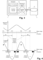
- Figure 4 shows in the upper graph the course of the magnetic energy E of the electric motor 10, as a function of or depending on the motor angle ⁇ (or the motor position, respectively).
- the lower graph of Figure 4 shows the course of the cogging torque C of the electric motor 10, as a function of or depending on the motor angle ⁇ (or the motor position, respectively).
- the stable positions P1, P2 (and ranges R1, R2) are stored in a data store of the motor controller 11 or its circuit 12, respectively.
- the stable positions P1, P2 (and ranges R1, R2) are determined by performing a calculation, based on a known configuration of the magnetic poles of the stator and the rotor of the electric motor 10, specifically based on the number of magnetic poles on the stator (e.g.
- the circuit 12 of the motor controller 11 controls the electric motor 10 to move in incremental steps, e.g. a rotation of one degree or of a partial degree, and determines the motor torque required to maintain the motor position at the incremental steps. Subsequently, the set of stable positions are determined as those incremental steps which require the smallest motor torque to maintain the motor position.
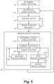
- step S1 the motor controller 11 or its circuit 12, respectively, receives or sets a target position for the electric motor 10 or a target value that relates to a target position for the electric motor 10.
- the target position or target value is defined and set by a building control system or a user terminal communicatively connected to the electric motor 10.
- step S2 the motor controller 11 or its circuit 12, respectively, controls the electric motor 10 to move to the set target position, e.g. to perform a certain number of rotations corresponding to a set rotary position (angle) or for driving an actuated part to a set (actuated) position.
- the motor controller 11 uses the position controller 121, the speed controller 122, the limiter 124, and the current controller 125 to control the electric motor 10 to reach the target position.
- step S3 the motor controller 11 or its circuit 12, respectively, determines whether the electric motor 10 or the actuated part, respectively, has reached the target position. Specifically, the position feedback module 126 determines and indicates the current position of the electric motor and/or the actuated part driven by the electric motor 10. If the target position has not been reached yet, control of the electric motor 10 is continued in step S2; otherwise, if the target position has been reached, a process of maintaining the current motor position is activated. For example, for that purpose, the position feedback module 126 or the circuit 12 or motor controller 11, respectively, activates the holding control torque controller 123.
- step S4 the holding control torque controller 123 or the circuit 12 or motor controller 11, respectively, controls the electric motor 10 to maintain its position at the current position or target position, respectively, as described below in more detail with reference to sub-steps S41, S42, S43, S44, and S45.
- external forces and influences such as a wind gust on a damper blade 21 of an external air damper 2 or a pressure change inside a fluid duct, will have an impact on the motor position and will have to be compensated by adapting the motor torque or motor current, respectively, to hold against the external force or influence, such as to maintain a target position.
- step S41 the holding control torque controller 123 or the circuit 12 or motor controller 11, respectively, determines the stable position closest to the target position or current position of the electric motor 10.
- step S42 the holding control torque controller 123 or the circuit 12 or motor controller 11, respectively, checks whether the current position of the electric motor 10 is within the range R1, R2 around the stable position P1, P2 determined in step S41. If the current position is within the respective range R1, R2, the process proceeds in step S43; otherwise, if the current position is outside the respective range R1, R2, processing proceeds in step S45 by increasing the motor torque or motor current, respectively.
- step S43 the holding control torque controller 123 or the circuit 12 or motor controller 11, respectively, checks whether the current motor torque or the motor current, respectively, is at zero, i.e. whether the electric motor 10 maintains its current position without requiring any motor current and, thus, not producing motor torque. If the current motor torque or the motor current, respectively, is at zero, the torque is maintained at zero and the processing continues in step S42. Otherwise, if the current motor torque or the motor current, respectively, is not at zero, processing continues in step S44 by reducing the motor torque or motor current, respectively.
- step S44 the holding control torque controller 123 or the circuit 12 or motor controller 11, respectively, reduces the motor torque or the motor current, respectively, e.g. by a predetermined amount or portion.
- the holding control torque controller 123 or the circuit 12 or motor controller 11, respectively determines the duration, e.g. in terms of time or number of cycles, during which the motor torque or the motor current, respectively, is not at zero. If this "non-zero torque duration" is longer than a defined threshold, e.g. one minute, five minutes or an hour, processing continues in step S0 by determining an alternative stable position.
- the alternative stable position is the stable position that is located preceding (before) or succeeding (following) the current stable position (previously selected in step S0). This approach makes it possible to find more advantageous stable positions which require less motor torque or motor current, respectively, through "trial and error".
- step S45 the holding control torque controller 123 or the circuit 12 or motor controller 11, respectively, increases the motor torque or motor current, respectively, e.g. by a predetermined amount or portion, and proceeds in step S42.
- step S45 the holding control torque controller 123 or the circuit 12 or motor controller 11, respectively, further determines and stores the motor torque present at the point where the motor position has reached an upper or lower boundary b1L, b1U, b2L, b2U of the defined range R1, R2 around the selected stable position P1, P2. Subsequently, when the motor torque or motor current, respectively, is reduced in step S44, it is not reduced beyond said recorded motor torque, which is thus used as a limit for reducing the motor torque.
Landscapes
- Engineering & Computer Science (AREA)
- Power Engineering (AREA)
- Chemical & Material Sciences (AREA)
- Combustion & Propulsion (AREA)
- Mechanical Engineering (AREA)
- General Engineering & Computer Science (AREA)
- Control Of Motors That Do Not Use Commutators (AREA)
- Control Of Electric Motors In General (AREA)
Claims (16)
- Ein Aktuator (1), der einen Elektromotor (10) mit einem Rastmoment (C) und eine Steuereinheit (11) umfasst, die so konfiguriert ist, dass sie den Betrieb des Elektromotors (10) steuert und eine Motorposition des Elektromotors (10) bestimmt, wobei die Steuereinheit (11) eine Schaltung (12) umfasst, die so konfiguriert ist, dass sie den Elektromotor (10) so steuert, dass er ein angetriebenes Bauteil (21) eines Heizungs-, Lüftungs- und Klimasystems zu einer Zielposition antreibt und eine aktuelle Motorposition aufrechterhält, indem aus einer Menge von stabilen Positionen (P1, P2), die durch das Rastmoment (C) definiert sind, eine ausgewählte stabile Position (P1, P2) gewählt wird, die der aktuellen Motorposition am nächsten liegt, und ein Motordrehmoment des Elektromotors (10) steuert, um die Motorposition innerhalb eines definierten Bereichs (R1, R2) um die ausgewählte stabile Position (P1, P2) herum aufrechtzuerhalten.
- Der Aktuator (1) nach Anspruch 1, wobei die Schaltung (12) so konfiguriert ist, dass sie das Motordrehmoment reduziert, solange die aktuelle Motorposition innerhalb des definierten Bereichs (R1, R2) um die ausgewählte stabile Position (P1, P2) liegt.
- Der Aktuator (1) nach Anspruch 2, wobei die Schaltung (12) so konfiguriert ist, dass sie das Motordrehmoment auf Null hält, wenn das Motordrehmoment auf Null verringert wurde und die aktuelle Position des Motors innerhalb des definierten Bereichs (R1, R2) um die ausgewählte stabile Position (P1, P2) liegt.
- Der Aktuator (1) nach einem der Ansprüche 1 bis 3, wobei die Schaltung (12) so konfiguriert ist, dass sie das Motordrehmoment erhöht, um die Motorposition innerhalb des definierten Bereichs (R1, R2) um die ausgewählte stabile Position (P1, P2) zurückzubringen, wenn die aktuelle Motorposition außerhalb des definierten Bereichs (R1, R2) um die ausgewählte stabile Position (P1, P2) bewegt worden ist.
- Der Aktuator (1) nach einem der Ansprüche 1 bis 4, wobei die Schaltung (12) konfiguriert ist, um einen Wert des Motordrehmoments zu erfassen, wenn die aktuelle Motorposition eine Grenze (b1L, b1U, b2L, b2U) des definierten Bereichs (R1, R2) um die ausgewählte stabile Position (P1, P2) erreicht hat, um das Motordrehmoment zu erhöhen, um die Motorposition innerhalb des definierten Bereichs (R1, R2) um die ausgewählte stabile Position (P1, P2) zu bringen, und das Motordrehmoment zu verringern, solange die aktuelle Motorposition innerhalb des definierten Bereichs (R1, R2) um die ausgewählte stabile Position (P1, P2) liegt, wobei der erfasste Wert des Motordrehmoments zum Bestimmen eines Grenzwerts zum Verringern des Motordrehmoments verwendet wird.
- Der Aktuator (1) nach einem der Ansprüche 1 bis 5, wobei die Schaltung (12) so konfiguriert ist, dass sie die Menge der stabilen Positionen (P1, P2) bestimmt, indem sie den Elektromotor (10) so steuert, dass er sich in inkrementellen Schritten bewegt, das Motordrehmoment bestimmend, um die Motorposition bei den inkrementellen Schritten aufrechtzuerhalten, und die Menge der stabilen Positionen (P1, P2) aus den inkrementellen Schritten bestimmt, die das kleinste Motordrehmoment zum Aufrechterhalten der Motorposition erfordern.
- Der Aktuator (1) nach einem der Ansprüche 1 bis 6, wobei der Aktuator (1) ferner einen elektrischen Energiespeicher (14) umfasst, der so konfiguriert ist, dass er den Elektromotor (10) im Falle eines Stromausfalls in eine definierte Sicherheitsposition fährt.
- Der Aktuator (1) nach einem der Ansprüche 1 bis 7, wobei der Elektromotor (10) ein bürstenloser Gleichstrommotor ist.
- Eine Klappe für ein Heizungs-, Lüftungs- und Klimatisierungssystem, umfassend eine Klappenschaufel (21) und einen Aktuator (1) nach einem der Ansprüche 1 bis 8, der mit der Klappenschaufel (21) zum Bewegen der Klappenschaufel (21) gekoppelt ist.
- Ein Verfahren zur Kontrolle eines Elektromotors (10), um ein angetriebenes Bauteil (21) eines Heizungs-, Lüftungs-, und Klimatisierungssystems zu einer Zielposition anzutreiben und eine aktuelle Motorposition aufrechtzuerhalten, wobei das Verfahren umfasst, dass eine Steuereinheit (11) die aktuelle Motorposition des Elektromotors (10) bestimmt, wobei die Steuereinheit (11) aus einer Menge von stabilen Positionen (P1, P2), die durch das Rastmoment (C) des Elektromotors (10) definiert sind, eine ausgewählte stabile Position (P1, P2) bestimmt (S41), die der aktuellen Motorposition am nächsten liegt, und die Steuereinheit (11) ein Motordrehmoment des Elektromotors (10) steuert, um die Motorposition innerhalb eines definierten Bereichs (R1, R2) um die ausgewählte stabile Position (P1, P2) aufrecht zu erhalten.
- Das Verfahren nach Anspruch 10 ferner umfassend dass die Steuereinheit (11) das Motordrehmoment verringert (S44), solange die aktuelle Position des Motors innerhalb des definierten Bereichs (R1, R2) um die ausgewählte stabile Position (P1, P2) liegt.
- Das Verfahren nach Anspruch 11 ferner umfassend dass die Steuereinheit (11) das Motordrehmoment auf Null hält, wenn das Motordrehmoment auf Null reduziert wurde und die aktuelle Motorposition innerhalb des definierten Bereichs (R1, R2) um die ausgewählte stabile Position (P1, P2) liegt.
- Das Verfahren nach einem der Ansprüche 10 bis 12, ferner umfassend dass die Steuereinheit (11) das Motordrehmoment erhöht (S45), um die Motorposition innerhalb des definierten Bereichs (R1, R2) um die ausgewählte stabile Position (P1, P2) zurückzubringen, wenn die aktuelle Motorposition außerhalb des definierten Bereichs (R1, R2) um die ausgewählte stabile Position (P1, P2) bewegt wurde.
- Das Verfahren nach einem der Ansprüche 10 bis 13, ferner umfassend dass die Steuereinheit (11) einen Wert des Motordrehmoments erfasst, wenn die aktuelle Motorposition eine Grenze des definierten Bereichs (R1, R2) um die ausgewählte stabile Position (P1, P2) erreicht hat, wobei die Steuereinheit (11) das Motordrehmoment erhöht (S46), um die Motorposition wieder in den definierten Bereich (R1, R2) um die ausgewählte stabile Position (P1, P2) zurückzubringen, und die Steuereinheit (11) das Motordrehmoment reduziert (S44), solange die aktuelle Motorposition innerhalb des definierten Bereichs (R1, R2) um die ausgewählte stabile Position (P1, P2) liegt, wobei der erfasste Wert des Motordrehmoments zum Bestimmen einer Grenze für das Verringern des Motordrehmoments verwendet wird.
- Das Verfahren nach einem der Ansprüche 10 bis 14, ferner umfassend dass die Steuereinheit (11) die Menge der stabilen Positionen (P1, P2) bestimmt (S0), indem sie den Elektromotor (10) so steuert, dass er sich in inkrementellen Schritten bewegt, das Motordrehmoment bestimmt, um die Motorposition in den inkrementellen Schritten aufrechtzuerhalten, und die Menge der stabilen Positionen (P1, P2) aus den inkrementellen Schritten bestimmt, die das kleinste Motordrehmoment erfordern, um die Motorposition aufrechtzuerhalten.
- Computerprogrammprodukt, umfassend ein nicht flüchtiges computerlesbares Medium, auf dem ein Computerprogrammcode gespeichert ist, der so konfiguriert ist, dass er einen Prozessor eines Aktuators (1) so steuert, dass der Prozessor einen Elektromotor (10) des Aktuators (1) steuert, um ein angetriebenes Bauteil (21) eines Heizungs-, Lüftungs-, und Klimatisierungssystems in eine Zielposition zu fahren und eine aktuelle Motorposition aufrechtzuerhalten, durch Bestimmen der aktuellen Motorposition des Elektromotors (10), Bestimmen (S41) einer ausgewählten stabilen Position (P1, P2), die der aktuellen Motorposition am nächsten liegt, aus einer Menge stabiler Positionen (P1, P2), die durch das Rastmoment (C) des Elektromotors (10) definiert sind, und Steuern eines Motordrehmoments des Elektromotors (10), um die Motorposition innerhalb eines definierten Bereichs (R1, R2) um die ausgewählte stabile Position (P1, P2) aufrecht zu erhalten.
Applications Claiming Priority (2)
| Application Number | Priority Date | Filing Date | Title |
|---|---|---|---|
| CH10632018 | 2018-09-07 | ||
| PCT/EP2019/073652 WO2020049079A1 (en) | 2018-09-07 | 2019-09-05 | An actuator with an electric motor and a method of controlling the electric motor to maintain a current position |
Publications (2)
| Publication Number | Publication Date |
|---|---|
| EP3847744A1 EP3847744A1 (de) | 2021-07-14 |
| EP3847744B1 true EP3847744B1 (de) | 2025-01-15 |
Family
ID=63524014
Family Applications (1)
| Application Number | Title | Priority Date | Filing Date |
|---|---|---|---|
| EP19765451.0A Active EP3847744B1 (de) | 2018-09-07 | 2019-09-05 | Stellantrieb mit einem elektromotor und verfahren zur steuerung des elektromotors zur bewahrung einer aktuellen position |
Country Status (4)
| Country | Link |
|---|---|
| US (3) | US11888429B2 (de) |
| EP (1) | EP3847744B1 (de) |
| CN (1) | CN112740536A (de) |
| WO (1) | WO2020049079A1 (de) |
Families Citing this family (4)
| Publication number | Priority date | Publication date | Assignee | Title |
|---|---|---|---|---|
| WO2023282702A1 (ko) | 2021-07-09 | 2023-01-12 | 주식회사 카나프테라퓨틱스 | Shp2 억제제 및 이의 용도 |
| CN121039580A (zh) | 2023-02-28 | 2025-11-28 | 贝利莫控股公司 | 带有无刷永磁马达的致动器 |
| WO2026027134A1 (de) * | 2024-07-29 | 2026-02-05 | Siemens Schweiz Ag | Spring-return-stellantrieb mit einem gleichstrommotor mit rastmomenthemmung zum ver- und entrasten eines stellelements des stellantriebs in und aus einer betätigungsposition |
| US12654569B2 (en) * | 2024-11-25 | 2026-06-16 | Fca Us Llc | Motor cogging torque management for driver comfort and confidence |
Family Cites Families (12)
| Publication number | Priority date | Publication date | Assignee | Title |
|---|---|---|---|---|
| DE19843123A1 (de) | 1998-09-21 | 2000-04-20 | Bosch Gmbh Robert | Elektrische Bremse mit Haltebremsfunktion |
| DE10062025C1 (de) | 2000-12-13 | 2002-07-25 | Siemens Ag | Verfahren und Antriebssteuerung für einen lagegeregelten Stillstand eines elektrischen Antriebs in einer vorgegebenen Sollposition |
| JP4455987B2 (ja) * | 2004-12-28 | 2010-04-21 | トヨタ自動車株式会社 | 車両用スタビライザシステム |
| CN101454960B (zh) * | 2006-05-24 | 2011-11-30 | 贝利莫控股公司 | 活门或者阀的安全驱动装置 |
| JP5419360B2 (ja) * | 2008-01-28 | 2014-02-19 | キヤノン株式会社 | 光学機器 |
| JP2010144596A (ja) * | 2008-12-18 | 2010-07-01 | Toyota Motor Corp | 内燃機関の制御装置 |
| US8395345B2 (en) * | 2009-01-28 | 2013-03-12 | Mitsubishi Electric Corporation | Valve control device |
| CH702059A1 (de) | 2009-10-23 | 2011-04-29 | Belimo Holding Ag | Bürstenloser gleichstrommotor mit stromloser hemmung. |
| US8587233B2 (en) * | 2010-01-25 | 2013-11-19 | Sntech, Inc. | Speed-defined torque control |
| US8947031B1 (en) * | 2012-06-26 | 2015-02-03 | Johnson Controls Technology Company | Systems and method for speed and torque control of a DC motor |
| US9465370B2 (en) * | 2012-06-26 | 2016-10-11 | Johnson Controls Technology Company | HVAC actuator with soft stall control |
| US9559623B2 (en) * | 2013-08-30 | 2017-01-31 | Regal Beloit America, Inc. | Method of controlling an electrical machine |
-
2019
- 2019-09-05 EP EP19765451.0A patent/EP3847744B1/de active Active
- 2019-09-05 US US17/263,950 patent/US11888429B2/en active Active
- 2019-09-05 CN CN201980058029.6A patent/CN112740536A/zh active Pending
- 2019-09-05 WO PCT/EP2019/073652 patent/WO2020049079A1/en not_active Ceased
-
2024
- 2024-01-29 US US18/425,727 patent/US12494724B2/en active Active
-
2025
- 2025-11-18 US US19/392,557 patent/US20260135500A1/en active Pending
Also Published As
| Publication number | Publication date |
|---|---|
| WO2020049079A1 (en) | 2020-03-12 |
| US20260135500A1 (en) | 2026-05-14 |
| US12494724B2 (en) | 2025-12-09 |
| EP3847744A1 (de) | 2021-07-14 |
| US20210313911A1 (en) | 2021-10-07 |
| US20240171096A1 (en) | 2024-05-23 |
| US11888429B2 (en) | 2024-01-30 |
| CN112740536A (zh) | 2021-04-30 |
Similar Documents
| Publication | Publication Date | Title |
|---|---|---|
| US12494724B2 (en) | Actuator with an electric motor and a method of controlling the electric motor to maintain a current position | |
| EP3568909B1 (de) | Kraftgefühl mittels bürstenlosem gleichstrommotor | |
| US10948073B2 (en) | Shift range control device | |
| EP1710904B1 (de) | Steuerung für bürstenlosen Gleichstrommotor | |
| CN101688478A (zh) | 用于控制阀装置的方法和系统 | |
| US20190360581A1 (en) | Shift range control device | |
| JP6623987B2 (ja) | シフトレンジ制御装置 | |
| EP0786710B1 (de) | Positionierungssystem mit Geschwindigkeitsregelung und Positionsregelung unter Verwendung des Geschwindigkeitsprofiles | |
| US8310193B2 (en) | Minimum temperature control for electromechanical actuator | |
| US7064508B2 (en) | Actuator position control system | |
| US7042189B2 (en) | Controlling an electric motor | |
| EP3942208B1 (de) | Verfahren zum betrieb eines steuerventils, heizungs-, lüftungs- und klimaanlagen stellantrieb und computer programm produkt | |
| US7656115B2 (en) | Calibrating stepper motor by driving fractional ranges | |
| EP3175543B1 (de) | Motorsteuerungssystem und -verfahren | |
| JP6109419B2 (ja) | 電子整流式サーボモータを動作させる方法及び装置、並びに、サーボモータを有する位置決めシステム | |
| KR101738227B1 (ko) | 유체의 관류를 차단 또는 조절하기 위한 자동차 공기 조화 시스템용 작동 소자 | |
| JP7552496B2 (ja) | 駆動装置の制御装置及び駆動システム | |
| JP7714027B2 (ja) | 電気モータを作動させる方法、制御装置、ピストンポンプ | |
| EP1745339B1 (de) | Verfahren zur steuerung eines elektromechanischen servomechanismus mit hoher reibung zur minimierung der benötigten energie zum halten eines geladenen ausgangsteils | |
| CN102007684A (zh) | 具有零点初始化的传导装置 | |
| CN119704262B (zh) | 一种轮式机器人驻车与起步控制方法 | |
| JP2009257471A (ja) | 電動アクチュエータの制御装置および制御方法 | |
| CN121611799A (zh) | 一种暖通领域热控阀阀位的自动恢复方法 | |
| KR20190051553A (ko) | 쿨링팬의 항력 저감 장치 및 쿨링팬 항력 저감 방법 |
Legal Events
| Date | Code | Title | Description |
|---|---|---|---|
| STAA | Information on the status of an ep patent application or granted ep patent |
Free format text: STATUS: UNKNOWN |
|
| STAA | Information on the status of an ep patent application or granted ep patent |
Free format text: STATUS: THE INTERNATIONAL PUBLICATION HAS BEEN MADE |
|
| PUAI | Public reference made under article 153(3) epc to a published international application that has entered the european phase |
Free format text: ORIGINAL CODE: 0009012 |
|
| STAA | Information on the status of an ep patent application or granted ep patent |
Free format text: STATUS: REQUEST FOR EXAMINATION WAS MADE |
|
| 17P | Request for examination filed |
Effective date: 20210308 |
|
| AK | Designated contracting states |
Kind code of ref document: A1 Designated state(s): AL AT BE BG CH CY CZ DE DK EE ES FI FR GB GR HR HU IE IS IT LI LT LU LV MC MK MT NL NO PL PT RO RS SE SI SK SM TR |
|
| DAV | Request for validation of the european patent (deleted) | ||
| DAX | Request for extension of the european patent (deleted) | ||
| STAA | Information on the status of an ep patent application or granted ep patent |
Free format text: STATUS: EXAMINATION IS IN PROGRESS |
|
| 17Q | First examination report despatched |
Effective date: 20230119 |
|
| GRAP | Despatch of communication of intention to grant a patent |
Free format text: ORIGINAL CODE: EPIDOSNIGR1 |
|
| STAA | Information on the status of an ep patent application or granted ep patent |
Free format text: STATUS: GRANT OF PATENT IS INTENDED |
|
| INTG | Intention to grant announced |
Effective date: 20240902 |
|
| GRAJ | Information related to disapproval of communication of intention to grant by the applicant or resumption of examination proceedings by the epo deleted |
Free format text: ORIGINAL CODE: EPIDOSDIGR1 |
|
| STAA | Information on the status of an ep patent application or granted ep patent |
Free format text: STATUS: EXAMINATION IS IN PROGRESS |
|
| GRAP | Despatch of communication of intention to grant a patent |
Free format text: ORIGINAL CODE: EPIDOSNIGR1 |
|
| STAA | Information on the status of an ep patent application or granted ep patent |
Free format text: STATUS: GRANT OF PATENT IS INTENDED |
|
| GRAS | Grant fee paid |
Free format text: ORIGINAL CODE: EPIDOSNIGR3 |
|
| INTC | Intention to grant announced (deleted) | ||
| GRAA | (expected) grant |
Free format text: ORIGINAL CODE: 0009210 |
|
| STAA | Information on the status of an ep patent application or granted ep patent |
Free format text: STATUS: THE PATENT HAS BEEN GRANTED |
|
| INTG | Intention to grant announced |
Effective date: 20241114 |
|
| AK | Designated contracting states |
Kind code of ref document: B1 Designated state(s): AL AT BE BG CH CY CZ DE DK EE ES FI FR GB GR HR HU IE IS IT LI LT LU LV MC MK MT NL NO PL PT RO RS SE SI SK SM TR |
|
| REG | Reference to a national code |
Ref country code: CH Ref legal event code: EP Ref country code: GB Ref legal event code: FG4D |
|
| REG | Reference to a national code |
Ref country code: DE Ref legal event code: R096 Ref document number: 602019064892 Country of ref document: DE |
|
| REG | Reference to a national code |
Ref country code: IE Ref legal event code: FG4D |
|
| P01 | Opt-out of the competence of the unified patent court (upc) registered |
Free format text: CASE NUMBER: APP_4772/2025 Effective date: 20250129 |
|
| REG | Reference to a national code |
Ref country code: NL Ref legal event code: MP Effective date: 20250115 |
|
| PG25 | Lapsed in a contracting state [announced via postgrant information from national office to epo] |
Ref country code: NL Free format text: LAPSE BECAUSE OF FAILURE TO SUBMIT A TRANSLATION OF THE DESCRIPTION OR TO PAY THE FEE WITHIN THE PRESCRIBED TIME-LIMIT Effective date: 20250115 |
|
| PG25 | Lapsed in a contracting state [announced via postgrant information from national office to epo] |
Ref country code: RS Free format text: LAPSE BECAUSE OF FAILURE TO SUBMIT A TRANSLATION OF THE DESCRIPTION OR TO PAY THE FEE WITHIN THE PRESCRIBED TIME-LIMIT Effective date: 20250415 |
|
| PG25 | Lapsed in a contracting state [announced via postgrant information from national office to epo] |
Ref country code: FI Free format text: LAPSE BECAUSE OF FAILURE TO SUBMIT A TRANSLATION OF THE DESCRIPTION OR TO PAY THE FEE WITHIN THE PRESCRIBED TIME-LIMIT Effective date: 20250115 |
|
| PG25 | Lapsed in a contracting state [announced via postgrant information from national office to epo] |
Ref country code: PL Free format text: LAPSE BECAUSE OF FAILURE TO SUBMIT A TRANSLATION OF THE DESCRIPTION OR TO PAY THE FEE WITHIN THE PRESCRIBED TIME-LIMIT Effective date: 20250115 |
|
| PG25 | Lapsed in a contracting state [announced via postgrant information from national office to epo] |
Ref country code: ES Free format text: LAPSE BECAUSE OF FAILURE TO SUBMIT A TRANSLATION OF THE DESCRIPTION OR TO PAY THE FEE WITHIN THE PRESCRIBED TIME-LIMIT Effective date: 20250115 |
|
| REG | Reference to a national code |
Ref country code: LT Ref legal event code: MG9D |
|
| PG25 | Lapsed in a contracting state [announced via postgrant information from national office to epo] |
Ref country code: IS Free format text: LAPSE BECAUSE OF FAILURE TO SUBMIT A TRANSLATION OF THE DESCRIPTION OR TO PAY THE FEE WITHIN THE PRESCRIBED TIME-LIMIT Effective date: 20250515 Ref country code: NO Free format text: LAPSE BECAUSE OF FAILURE TO SUBMIT A TRANSLATION OF THE DESCRIPTION OR TO PAY THE FEE WITHIN THE PRESCRIBED TIME-LIMIT Effective date: 20250415 |
|
| REG | Reference to a national code |
Ref country code: AT Ref legal event code: MK05 Ref document number: 1760486 Country of ref document: AT Kind code of ref document: T Effective date: 20250115 |
|
| PG25 | Lapsed in a contracting state [announced via postgrant information from national office to epo] |
Ref country code: HR Free format text: LAPSE BECAUSE OF FAILURE TO SUBMIT A TRANSLATION OF THE DESCRIPTION OR TO PAY THE FEE WITHIN THE PRESCRIBED TIME-LIMIT Effective date: 20250115 |
|
| PG25 | Lapsed in a contracting state [announced via postgrant information from national office to epo] |
Ref country code: LV Free format text: LAPSE BECAUSE OF FAILURE TO SUBMIT A TRANSLATION OF THE DESCRIPTION OR TO PAY THE FEE WITHIN THE PRESCRIBED TIME-LIMIT Effective date: 20250115 Ref country code: PT Free format text: LAPSE BECAUSE OF FAILURE TO SUBMIT A TRANSLATION OF THE DESCRIPTION OR TO PAY THE FEE WITHIN THE PRESCRIBED TIME-LIMIT Effective date: 20250515 |
|
| PG25 | Lapsed in a contracting state [announced via postgrant information from national office to epo] |
Ref country code: BG Free format text: LAPSE BECAUSE OF FAILURE TO SUBMIT A TRANSLATION OF THE DESCRIPTION OR TO PAY THE FEE WITHIN THE PRESCRIBED TIME-LIMIT Effective date: 20250115 Ref country code: GR Free format text: LAPSE BECAUSE OF FAILURE TO SUBMIT A TRANSLATION OF THE DESCRIPTION OR TO PAY THE FEE WITHIN THE PRESCRIBED TIME-LIMIT Effective date: 20250416 |
|
| PG25 | Lapsed in a contracting state [announced via postgrant information from national office to epo] |
Ref country code: AT Free format text: LAPSE BECAUSE OF FAILURE TO SUBMIT A TRANSLATION OF THE DESCRIPTION OR TO PAY THE FEE WITHIN THE PRESCRIBED TIME-LIMIT Effective date: 20250115 |
|
| PG25 | Lapsed in a contracting state [announced via postgrant information from national office to epo] |
Ref country code: SE Free format text: LAPSE BECAUSE OF FAILURE TO SUBMIT A TRANSLATION OF THE DESCRIPTION OR TO PAY THE FEE WITHIN THE PRESCRIBED TIME-LIMIT Effective date: 20250115 |
|
| REG | Reference to a national code |
Ref country code: CH Ref legal event code: U11 Free format text: ST27 STATUS EVENT CODE: U-0-0-U10-U11 (AS PROVIDED BY THE NATIONAL OFFICE) Effective date: 20251001 |
|
| PG25 | Lapsed in a contracting state [announced via postgrant information from national office to epo] |
Ref country code: SM Free format text: LAPSE BECAUSE OF FAILURE TO SUBMIT A TRANSLATION OF THE DESCRIPTION OR TO PAY THE FEE WITHIN THE PRESCRIBED TIME-LIMIT Effective date: 20250115 |
|
| PG25 | Lapsed in a contracting state [announced via postgrant information from national office to epo] |
Ref country code: DK Free format text: LAPSE BECAUSE OF FAILURE TO SUBMIT A TRANSLATION OF THE DESCRIPTION OR TO PAY THE FEE WITHIN THE PRESCRIBED TIME-LIMIT Effective date: 20250115 |
|
| PGFP | Annual fee paid to national office [announced via postgrant information from national office to epo] |
Ref country code: DE Payment date: 20250919 Year of fee payment: 7 |
|
| PG25 | Lapsed in a contracting state [announced via postgrant information from national office to epo] |
Ref country code: IT Free format text: LAPSE BECAUSE OF FAILURE TO SUBMIT A TRANSLATION OF THE DESCRIPTION OR TO PAY THE FEE WITHIN THE PRESCRIBED TIME-LIMIT Effective date: 20250115 |
|
| REG | Reference to a national code |
Ref country code: DE Ref legal event code: R097 Ref document number: 602019064892 Country of ref document: DE |
|
| PG25 | Lapsed in a contracting state [announced via postgrant information from national office to epo] |
Ref country code: EE Free format text: LAPSE BECAUSE OF FAILURE TO SUBMIT A TRANSLATION OF THE DESCRIPTION OR TO PAY THE FEE WITHIN THE PRESCRIBED TIME-LIMIT Effective date: 20250115 Ref country code: CZ Free format text: LAPSE BECAUSE OF FAILURE TO SUBMIT A TRANSLATION OF THE DESCRIPTION OR TO PAY THE FEE WITHIN THE PRESCRIBED TIME-LIMIT Effective date: 20250115 |
|
| PG25 | Lapsed in a contracting state [announced via postgrant information from national office to epo] |
Ref country code: RO Free format text: LAPSE BECAUSE OF FAILURE TO SUBMIT A TRANSLATION OF THE DESCRIPTION OR TO PAY THE FEE WITHIN THE PRESCRIBED TIME-LIMIT Effective date: 20250115 |
|
| PG25 | Lapsed in a contracting state [announced via postgrant information from national office to epo] |
Ref country code: SK Free format text: LAPSE BECAUSE OF FAILURE TO SUBMIT A TRANSLATION OF THE DESCRIPTION OR TO PAY THE FEE WITHIN THE PRESCRIBED TIME-LIMIT Effective date: 20250115 |
|
| PLBE | No opposition filed within time limit |
Free format text: ORIGINAL CODE: 0009261 |
|
| STAA | Information on the status of an ep patent application or granted ep patent |
Free format text: STATUS: NO OPPOSITION FILED WITHIN TIME LIMIT |
|
| 26N | No opposition filed |
Effective date: 20251016 |
|
| PGFP | Annual fee paid to national office [announced via postgrant information from national office to epo] |
Ref country code: CH Payment date: 20251001 Year of fee payment: 7 |
|
| PG25 | Lapsed in a contracting state [announced via postgrant information from national office to epo] |
Ref country code: LU Free format text: LAPSE BECAUSE OF NON-PAYMENT OF DUE FEES Effective date: 20250905 |
|
| GBPC | Gb: european patent ceased through non-payment of renewal fee |
Effective date: 20250905 |
|
| REG | Reference to a national code |
Ref country code: BE Ref legal event code: MM Effective date: 20250930 |
|
| PG25 | Lapsed in a contracting state [announced via postgrant information from national office to epo] |
Ref country code: LT Free format text: LAPSE BECAUSE OF FAILURE TO SUBMIT A TRANSLATION OF THE DESCRIPTION OR TO PAY THE FEE WITHIN THE PRESCRIBED TIME-LIMIT Effective date: 20250115 |
|
| PG25 | Lapsed in a contracting state [announced via postgrant information from national office to epo] |
Ref country code: MC Free format text: LAPSE BECAUSE OF FAILURE TO SUBMIT A TRANSLATION OF THE DESCRIPTION OR TO PAY THE FEE WITHIN THE PRESCRIBED TIME-LIMIT Effective date: 20250115 |
|
| PG25 | Lapsed in a contracting state [announced via postgrant information from national office to epo] |
Ref country code: GB Free format text: LAPSE BECAUSE OF NON-PAYMENT OF DUE FEES Effective date: 20250905 |
|
| PG25 | Lapsed in a contracting state [announced via postgrant information from national office to epo] |
Ref country code: BE Free format text: LAPSE BECAUSE OF NON-PAYMENT OF DUE FEES Effective date: 20250930 Ref country code: IE Free format text: LAPSE BECAUSE OF NON-PAYMENT OF DUE FEES Effective date: 20250905 |
|
| PG25 | Lapsed in a contracting state [announced via postgrant information from national office to epo] |
Ref country code: FR Free format text: LAPSE BECAUSE OF NON-PAYMENT OF DUE FEES Effective date: 20250930 |