EP3847112B1 - Systèmes et procédés de bande transporteuse à fil plat supérieur modulaire - Google Patents
Systèmes et procédés de bande transporteuse à fil plat supérieur modulaire Download PDFInfo
- Publication number
- EP3847112B1 EP3847112B1 EP19856622.6A EP19856622A EP3847112B1 EP 3847112 B1 EP3847112 B1 EP 3847112B1 EP 19856622 A EP19856622 A EP 19856622A EP 3847112 B1 EP3847112 B1 EP 3847112B1
- Authority
- EP
- European Patent Office
- Prior art keywords
- picket
- top plate
- trailing
- leading
- interface
- Prior art date
- Legal status (The legal status is an assumption and is not a legal conclusion. Google has not performed a legal analysis and makes no representation as to the accuracy of the status listed.)
- Active
Links
Images


Classifications
-
- B—PERFORMING OPERATIONS; TRANSPORTING
- B65—CONVEYING; PACKING; STORING; HANDLING THIN OR FILAMENTARY MATERIAL
- B65G—TRANSPORT OR STORAGE DEVICES, e.g. CONVEYORS FOR LOADING OR TIPPING, SHOP CONVEYOR SYSTEMS OR PNEUMATIC TUBE CONVEYORS
- B65G17/00—Conveyors having an endless traction element, e.g. a chain, transmitting movement to a continuous or substantially-continuous load-carrying surface or to a series of individual load-carriers; Endless-chain conveyors in which the chains form the load-carrying surface
- B65G17/06—Conveyors having an endless traction element, e.g. a chain, transmitting movement to a continuous or substantially-continuous load-carrying surface or to a series of individual load-carriers; Endless-chain conveyors in which the chains form the load-carrying surface having a load-carrying surface formed by a series of interconnected, e.g. longitudinal, links, plates, or platforms
- B65G17/08—Conveyors having an endless traction element, e.g. a chain, transmitting movement to a continuous or substantially-continuous load-carrying surface or to a series of individual load-carriers; Endless-chain conveyors in which the chains form the load-carrying surface having a load-carrying surface formed by a series of interconnected, e.g. longitudinal, links, plates, or platforms the surface being formed by the traction element
-
- B—PERFORMING OPERATIONS; TRANSPORTING
- B65—CONVEYING; PACKING; STORING; HANDLING THIN OR FILAMENTARY MATERIAL
- B65G—TRANSPORT OR STORAGE DEVICES, e.g. CONVEYORS FOR LOADING OR TIPPING, SHOP CONVEYOR SYSTEMS OR PNEUMATIC TUBE CONVEYORS
- B65G17/00—Conveyors having an endless traction element, e.g. a chain, transmitting movement to a continuous or substantially-continuous load-carrying surface or to a series of individual load-carriers; Endless-chain conveyors in which the chains form the load-carrying surface
- B65G17/30—Details; Auxiliary devices
- B65G17/38—Chains or like traction elements; Connections between traction elements and load-carriers
- B65G17/42—Attaching load carriers to traction elements
- B65G17/44—Attaching load carriers to traction elements by means excluding relative movements
Definitions
- the present invention relates to the technical field of flatwire conveyor belt assemblies.
- Flatwire conveyor belts which are typically constructed from metal strips (e.g., pickets or wickets) that are interconnected with cross-rods, continue to have applicability for a variety of conveying applications.
- the construction of flatwire conveyor belts offers an efficient strength-to-weight ratio that is relatively cost-effective to manufacture.
- One disadvantage of conventional flatwire conveyor belts relates to the relative openness of the conveying surface, which presents challenges for transporting product of a size and/or form factor that is incompatible with the relatively open conveying surface.
- conventional construction establishes larger open areas that can hamper effective carrying of correspondingly smaller products (e.g., products may pass partially through, become entangled with, or be unstable on the conveying surface).
- Conventional construction can also inhibit a smooth, continuous transfer of product both on to and off of the flatwire conveyor belt.
- Publications US 3 977 514 , US 7 931 139 and US 2 621 779 discloses a module capable of use in a flatwire conveyor belt assembly.
- the module comprises a picket having leading links and trailing links.
- the picket defines a picket leading portion proximate the leading links and a picket trailing portion proximate the trailing links.
- the module further comprises a top plate having a leading end and a trailing end and defining a top plate leading portion proximate the leading end and a top plate trailing portion proximate the trailing end.
- publication US 3 977 514 discloses a clip having multiple tabs configured to receive adjacent transverse conveyor bars.
- Publication US 7 931 139 further discloses cover plates having fingers configured to engage pintle rods.
- Publication US 2 621 779 includes plastic pieces connected to a metal body.
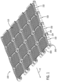
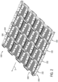
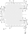
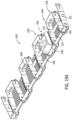
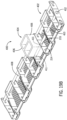
- FIGS. 1 and 2 Several rows of a flatwire conveyor belt 100 in accordance with one example embodiment are depicted in FIGS. 1 and 2 .
- the flatwire conveyor belt 100 is typically an endless belt driven in a direction of travel (designated by arrow D), and constructed to address particular application requirements.
- Each row 102 includes a picket 200 that supports multiple modular top plates 300. Adjacent rows 102 are interconnected by a cross-rod 104 that extends laterally (relative to the direction of travel D) through the pickets 200 and the top plates 300, generally forming a hinge connection.
- each picket 200 allows for adjacent pickets 200 to be interconnected and provides for interface features that allow the top plates 300 to be secured to, in some embodiments, both the picket 200 and the cross-rod 104.
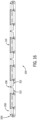
- the example picket 200 is shown and described with additional reference to FIGS. 3-5 , and is typically manufactured and formed from a single metallic strip having a generally uniform cross-section.
- the pickets 200 are shown to define a specific pitch P (i.e., a center-to-center distance between adjacent cross-rods 104) and a specific opening width W (i.e., a nominal form to allow nesting and intermeshing of an adjacent picket 200), the form factor of the picket 200 can be adapted to address application-specific requirements (e.g., weight of product, speed of conveyance, overall conveyor belt envelope constraints, etc.).
- the example picket 200 includes edge links 202 that flank alternating leading links 204 and trailing links 206. While the form factor of the edge links 202, leading links 204, and trailing links 206 can be generally uniform in particular applications, the edge links 202 in the example embodiment are narrower than the individual leading links 204 and trailing links 206. Specifically, the edge links 202 define an edge end portion 208 that is approximately half the size of a leading end portion 210 of the leading link 204 or a trailing end portion 212 of the trailing link 206.
- the leading links 204 and the trailing links 206 are generally U-shaped (as viewed in FIG. 4 ) having pairs of leg portions 216 formed generally orthogonally to the respective leading end portion 210 and trailing end portion 212. Adjacent leg portions 216 of laterally spaced leading links 204 and trailing links 206 are bridged by side bars 214 that, in the example embodiment, are skewed relative to the pairs of leg portions 216.
- each edge link 202 varies from the leading links 204 and the trailing links 206 in some respects.
- the edge end portion 208 of each edge link 202 is also generally U-shaped (as viewed in FIG. 4 ) and defines an inner leg portion 218 and an outer leg portion 220 that are formed generally orthogonally to the edge end portion 208.
- a side bar 214 bridges the inner leg portion 218 and a leg portion 216 of the outermost trailing link 206.
- the outer leg portion 220 is bridged by a side bar 214 to an end bar 222 defined at a lateral side of the picket 200.
- example picket 200 includes a certain level of uniformity and repeating patterns to aid in manufacturing of the picket 200 and construction of a flatwire conveyor belt 100
- alternative embodiments may diverge from that shown to, for example, address application-specific requirements and/or goals.
- the example pickets 200 define other interface features that are tailored to engage and support top plates 300, such that when the flatwire conveyor belt 100 is traveling in a horizontal plane, the top plates 300 establish a generally continuous conveying surface 110 ( e.g., see FIG. 1 ).
- Each picket 200 defines a series of slots 228 formed in the edge end portion 208, the leading end portion 210, and the trailing end portion 212.
- the slots 228 are generally rectangular with rounded corners and are positioned above a midpoint and closer to the top of the picket 200.
- the edge end portions 208 are illustrated with a single slot 228 with each of the leading end portions 210 and the trailing end portions 212 defining two laterally spaced slots 228.
- the example slots 228 can also comprise a single angled slot, one or more circular opening, protrusion, or other form factor configured to interact with the mating form factor provided in the top plate 300 (discussed below).
- the particular form factor and positioning of the slots 228 can be adapted and/or altered to accommodate application requirements, manufacturing constraints, or other considerations (e.g., the slots 228 may be adapted to interact with a mating top plate 300 to provide a biasing force urging the top plate 300 into engagement with the picket 200).
- the slots 228 formed in the trailing end portion 212 of the trailing links 206 engage with a mating structure of the top plate 300 to define an example picket trailing interface portion of a trailing interface. The trailing interface establishes selective engagement between the picket 200 and the top plate 300 proximate the trailing end of each.
- An example leading interface establishes selective engagement between the picket 200 and the top plate 300 proximate the leading end of each, and a respective cross-rod 104.
- the picket 200 defines openings 230 that can aid in positioning, assembling, and restraining the top plate 300 at an example picket leading portion of the leading interface.
- the openings 230 are generally cylindrical, axially aligned, and extend through the various leg portions 216 of the edge links 202 and the leading links 204.
- the example openings 230 can also comprise, for instance, slots, protrusions, and notches, or any other form factor configured to interact with the mating form factor provided on the top plate 300 (discussed below).
- openings 230 are formed in the edge bars 222 and the trailing links 206.
- the openings 230 are generally uniform in form factor and are positioned at a midpoint between the upper and lower bounds of the picket 200.
- top plates 300 allow for each to be seated atop and interface with a supporting picket 200, while also being captured to a cross-rod 104 installed to hingedly interconnect adjacent pickets 200.
- the example top plate 300 is shown and described with additional reference to FIGS. 6-10 .
- the top plate 300 is manufactured and formed from a metallic sheet having a generally uniform thickness.
- the top plate 300 may be manufactured from other materials and processes; for instance, the top plate 300 can be molded from a polymeric material.
- the top plates 300 are shown as uniform modular components, it is appreciated that top plates of varying forms may be used when beneficial for a particular application.
- the example top plate 300 defines a generally planar transport surface 302 that includes an array of perforations 304, which can allow for drainage and airflow through the transport surface 302.
- the transport surfaces 302 of a plurality of top plates 300 can combine to collectively define the conveying surface 110.
- the perforations 304 can take on a variety of orientations, sizes, and form factors (see, for instance, FIG. 22 ), or be absent (shown, for example, in FIGS. 20-21 ) such that the transport surface 302 is generally continuous.
- the transport surface 302 can provide a textured or contoured surface that may improve frictional engagement and/or positive structural engagement between the transport surface 302 and a particular product to be conveyed.
- the top plates 300 can further include or define application-specific structures (e.g., resilient fingers, dividers, fights, etc.).
- the example top plate 300 engages the underlying picket 200 near a leading end 306 at the leading interface and near a trailing end 308 at the trailing interface.
- the leading end 306 also includes structures to engage a cross-rod 104 used to pivotally interconnect adjacent rows of pickets 200.
- the generally rectangular transport surface 302 of the top plate 300 is formed with downwardly extending side skirts 310, and includes a pair of arms 312 near the leading end 306 and an arcuate tail 314 near the trailing end 308.
- the arms 312 angle downward from the transport surface 302 at a curved portion 316 to a lower portion 318, such that the lower portion 318 is skewed relative to the transport surface 302.
- a tab 320 is formed at an orientation that generally extends orthogonally to the lower portion 318 in a direction toward the trailing end 308 and generally parallel with the side skirts 310.
- Each lower portion 318 of the respective tab 320 includes an outer side 328 that skews laterally inward toward the centerline C of the top plate 300 (illustrated in FIG. 9 ).
- Each tab 320 includes an opening 322 and an ear 324, which includes an arcuate upper end 326 that extends away from a centerline C of the top plate 300.
- the ears 324 can comprise a variety of form factors (e.g., protrusions, recesses, inserts, etc.) that are configured to mate and interface with the form factor defined by the picket leading interface portion (e.g., the example openings 230).
- the openings 322 are somewhat elongated and are sized and positioned to accommodate the cross-rod 104 during use; therefore, in the example embodiment, the top plates 300 are engaged with the pickets 200 prior to inserting the cross-rods 104 to interconnect adjacent rows of top plates 300 and supporting pickets 200.
- the tail 314 near the trailing end 308 curves downward and away from the transport surface 302, ultimately curving back toward the leading end 306 of the top plate 300 at a trailing edge 330 to define generally horizontal lip 332.
- the example tail 314 includes sides 334 that skew inward towards the centerline C of the top plate 300.
- a pair of laterally spaced tabs 336 extend from the lip 332 toward the leading end 306. Each tab 336 slightly tappers toward a tip 338, and the tabs 336 comprise a portion of the example top plate trailing interface portion of the trailing interface between the picket 200 and the top plate 300.
- the tabs 336 can take on a variety of form factors (e.g., openings, slots, grooves, protrusions, nibs, inserts, etc.), provided the top plate trailing interface portion and the picket trailing interface portion are adapted to interact at the trailing interface between the picket 200 and the top plate 300 to interface the top plate 300 and the picket 200.
- form factors e.g., openings, slots, grooves, protrusions, nibs, inserts, etc.
- the form factor of the top plate 300 includes features that generally maintain a desired spacing and orientation between adjacent top plates 300 during use.
- the curved portion 316 defines an arcuate segment 317 that has a leading radius of curvature LR extending from a leading pivot axis LP, and the tail 314 defines another accurate segment 315 that has a trialing radius of curvature TR extending from a trailing pivot axis TP.
- the example interface and engagement between the picket 200 and top plate 300 is described with additional reference to FIGS. 11-13 .
- the example picket 200 and the example top plate 300 are configured to interface at a leading interface and at a trailing interface (annotated in FIG. 11 as LI and TI, respectively).
- the leading interface includes a picket leading portion and a top plate leading portion that are both adapted to establish cooperating form factors that mate the picket 200 and the top plate 300 near leading ends.
- the picket 200 includes an example picket leading portion defining openings 230 that establish a form factor adapted to interface with an example top plate leading portion of the top plate 300 defining ears 324.
- the example leading interface can include the cooperation between the openings 224 of the picket 200, the openings 322 in the top plate 300, and the assembly of the cross-rod 104 through the openings 224, 322.
- the trailing interface includes a picket trailing portion and a top plate trailing portion that are both adapted to establish cooperating form factors that mate the picket 200 and the top plate 300 near trailing ends.
- the picket 200 includes an example picket trailing portion defining slots 228 that establish a form factor adapted to interface with an example top plate trailing portion of the top plate 300 defining tabs 336.
- the top plate 300 is generally aligned as shown in FIG. 11 (as annotated by engagement lines).
- the tabs 336 on the trailing end 308 of the top plate 300 are aligned for insertion into the slots 228 formed in the trailing end portions 212 of the trailing link 206.
- the tapered form factor of the tabs 336 can be configured to securely engage a receiving form factor defined by the structure of the slots 228.
- the opening 322 in one tab 320 is generally aligned with the opening 224 formed near the leg portion 216 of the edge link 202, and the other opening 322 of the other tab 320 is generally aligned with the opening 224 formed near the leg portion 216 of the leading link 204.
- the ear 324 of one tab 320 is generally aligned with the opening 230 formed in the leg portion 216 of the edge link 202, and the other ear 324 of the other tab 320 is generally aligned with the opening 230 formed in the leg portion 216 of the leading link 204.
- the contour of the ears 324 and the respective upper ends 326 are inserted by slight elastic deformation of, for instance, one or more of the picket 200, the ear 324, and the tab 320. Once engaged, the upper ends 326 of the ears 324 interfere with the boundary of the opening 230 to inhibit unintentional removal of the top plate 300, and can abate noise caused by excess relative movement of the top plate 300.
- the interaction between and relative placement of the ears 324 and the corresponding openings 230 establish positioning features that aid assembly of the top plates 300 to the pickets 200 by, for example, aligning the openings 230 in the picket 200 with the openings 322 in the top plate 300 (discussed below) to readily receive the cross-rod 104.
- the top plate 300 of FIG. 11 When the top plate 300 of FIG. 11 is installed, the top plate 300 extends between and generally covers the edge link 202, the laterally adjacent trailing link 206, and approximately half of the laterally adjacent leading link 204 (best illustrated in FIGS. 12 and 13 ). With specific reference to FIGS. 12 and 13 , another top plate 300 can be similarly assembled by again aligning the interconnecting interface features of the picket 200 and the additional top plate 300.
- the cross-rods 104 can be aligned with the respective openings 224, 226 in the edge links 204, leading links 206, and trailing links 208 of the pickets 200, and openings 322 in the tabs 320 of the top plates 300.
- the pickets 200 and top plates 300 can be modified such that the top plate 300 is secured to the pickets 200 by tabs 336 on the trailing end 308 and by similar tabs on the leading end 306.
- tabs on the leading end 306 may extend from the lower portion 318 of the top plate 300 and extend into the slots 228 formed in the edge link 202 and the leading links 204.
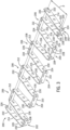
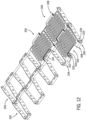
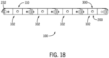
- FIGS. 14-18 A portion of the flatwire conveyor belt 100 illustrating four rows 102 is further shown in FIGS. 14-18 , and various additional features of the pickets 200 and the top plates 300 are illustrated.
- the top plates 300 are sized to provide a lateral space or gap 108 between laterally adjacent top plates 300. This provides, for instance, space to accommodate lateral compression of the underlying pickets 200 that can occur during assembly of the flatwire conveyor belt 100.
- the gap 108 can be sized to reduce the potential for products being conveyed to undesirably interact with the gap 108.
- the notches 232 formed in the edge end portions 208 of each edge link 202, the leading end portion 210 of the leading link 204, and the trailing end portion 212 of the trailing link 206 can accommodate a respective top plate 300, such that the top plate 300 is seated in preferred orientation relative to other top plates 300 and may be positioned generally directly on the picket 200.
- contours and form factors of the pickets 200 and the top plates 300 enhance hinging of the adjacent rows 102.
- the contours of the arms 312 at the leading end 306 and the tail 314 at the trailing end 308 can be configured to establish desired clearance for uninhibited rotation within a practical range of operation of the flatwire conveyor belt 100.
- each row 102 is generally identical and comprised of pickets 200 and top plates 300 of substantially similar form factors, respectively.
- the picket 200 and the top plate 300 include various contours provided to enhance manufacturability from strip/sheet material using, for instance, die cutting, stamping, and press forming processes.
- the spacing and construction of the picket and top plate can be adapted accordingly.
- top plates of varying form factor can be provide to establish a brick-lay pattern having offset top plate placement between adjacent rows, such that successive rows do not combine to establish continuous gaps or contours.
- a combination of top plates of discrete lateral dimensions e.g., 6 inches in lateral width and 3 inches in lateral width
- FIGS. 19A and 19B An alternative embodiment of an example portion of flatwire conveyor belt 400 is illustrated in FIGS. 19A and 19B . While many similarities to the flatwire conveyor belt 100 are present, a difference exists in that a picket 402 has been modified to accommodate and restrain a portion of a guide system.
- the guide system such as the Positrack system employed by Rexnord Corporation of Milwaukee, Wisconsin, can include a track or rail (not shown).
- the flatwire conveyor belt 400 includes a mating positioning element 404 that is configured to interact with the track or rail during operation of the flatwire conveyor belt 400.
- the example positioning element 404 includes various surfaces, such as lateral sides 406, which can be configured to ride along or engage with portions of the track or rail to direct, limit, or at least partially restrain undesired movement of the flatwire conveyor belt 400.
- the form factor of the example picket 402 is similar to picket 200.
- Picket 402 includes a series of openings 215 that are formed through select ones of the side bars 214. While the axis of each opening 215 is generally aligned, in one embodiment, the openings 215 formed in the respective side bar 214 of the end links 202 may be positioned slightly above the openings 215 formed in the remaining side bars 214 (shown best in FIG. 5 ). With specific reference to FIGS. 19A and 19B , the picket 402 differs in that at least side bar 408 does not include any opening (i.e., similar to openings 215).
- the example positioning element 404 can be seated between trailing links 206 and a guide rod 410, which is sized accordingly, can be inserted into the openings 215, through cylindrical channel or openings 411 in or through the positioning element 404, and generally abutted against side bar 408.
- This construction effectively captures the positioning element 404 with the picket 402.
- a rivet 412 (or other structure, such as a plug, a clip, etc.) can be used to block at least a portion of the outermost opening 215 formed in the edge link 202.
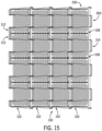
- top plate 500 is illustrated in FIGS. 20 and 21 . While the top plate 500 is similar to the top plate 300, various differences are shown.
- the top plate 500 includes leading arms 502, 504 that extend from a main body 506 in a leading direction, and a single trailing tail 508 that extends from the main body 506 in a trailing direction.
- the main body 506 includes a generally continuous, planar transport surface 507. Similar to the top plate 300, the tail 508 curves downward from the main body 506 and terminates in a pair of laterally spaced tabs 510.
- the tabs 510 are configured to interface with mating slots formed in a supporting picket (e.g., slots 228 formed in the trailing end portion 212 of the picket 200 shown in FIG. 11 ).
- the tail 508 further includes a series of openings 512 formed along a trailing end 514.
- Each arm 502, 504 includes a curved portion 516 that extends from the main body 506 and downward to terminate in a leading tab 518.
- the leading tabs 518 are generally rectangular in form factor and extend from distal ends of the arms 502, 504 toward the tail 508.
- the leading tabs 518 are configured to engage mating slots formed in the leading end portion of a picket, such as the slots 228 formed in the leading end portion 210 of the picket 200 (show in FIG. 3 ).
- the arms 502, 504 also include a series of openings 520 formed along a leading end 522.
- the alternative top plate 500 engages the underlying picket (e.g., picket 200) at a leading interface and at a trailing interface.
- the tabs 510 of the tail 508 are engaged with respective slots 228 formed in the trailing end portion 212 of the picket 200
- the leading tabs 518 are engaged with respective slots 228 formed in the leading end portion 210 of the picket 200.
- the top plate 500 and/or the picket (e.g., picket 200) may be elastically deformed or flexed to allow the top plate 500 to be aligned and releasably engaged with the underlying picket 200.
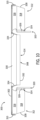
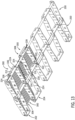
- top plate 600 is illustrated in FIG. 22 .
- the top plate 600 defines a main body 602 with an array of perforations 604 that extend through the main body 602 between a transport surface and an underside.
- Each perforation 604 is generally cylindrical and the array of perforations 604 is generally mirrored about line L.
- perforations may be non-uniform, both in individual form factor and/or in relative position on the top plate 600.
- One skilled in the art will understand the various alternatives that fall within the purview of the disclosed concepts.
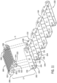
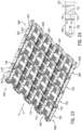
- FIG. 23 illustrates another flatwire conveyor belt 700 in accordance with one example embodiment.
- the flatwire conveyor belt 700 is similar to the flatwire conveyor belt 100 described above and is typically an endless belt driven in a direction of travel (designated by arrow D), and constructed to address particular application requirements.
- Each row 702 includes a picket 800 that supports multiple modular top plates 900.
- Adjacent rows 702 are interconnected by a first set of cross-rods 704 that extends laterally (relative to the direction of travel D) through the pickets 800, generally forming a hinge connection.
- a second set of cross-rods 712 also extends laterally through the pickets 800. As shown, the first set of cross-rods 704 and the second set of cross-rods 712 are provided in an alternating pattern; however, fewer of the second set of cross-rods 712 can be provided depending on the application-specific requirements.
- the first set of cross-rods 704 is typically engaged by one or more sprockets driven by a motor that rotates the sprocket(s) to engage and drive against the first set of cross-rods 704 from beneath the flatwire conveyor belt 700.
- the second set of cross-rods 712 extends through and supports rollers 714. Each of the rollers 714 can rotate about a respective cross-rod of the second set of cross-rods 712 freely and independently from each other, the pickets 800, and the modular top plates 900. In other forms, some or all of the rollers 714 may be rotatably secured to the cross-rods 712 such that the rollers 714 and cross-rods 712 rotate in unison.
- rollers 714 there may be greater or fewer rollers 714 per picket 800 (or per flatwire conveyor belt 700) than shown in FIG. 23 , as adjustments can be made depending on the application-specific requirements (e.g., load-carrying capacity requirements).
- the example rollers 714 are generally cylindrical with a central axial opening though which the cross-rods 712 extend. In alternative embodiments, the rollers 714 may take other form factors, such as tapered, arcuate, convex, concave, and the like.
- the rollers 714 can be constructed of, for instance, a variety of plastic and/or metallic materials, and may include an internal bushing, bearing, and the like within the central axial opening to influence the relative engagement with the cross-rods 712 (e.g., reduce sliding friction).
- both the first and second sets of cross-rods 704, 712 are metallic with ends 706, 716 that are formed or mushroomed to limit lateral movement (i.e., in a direction generally skewed to the direction of travel D) of the cross-rods 704, 712 once adjacent rows 702 are interconnected.
- other restraint mechanisms can be used to restrain the cross-rods, such as collars or clips, and the cross-rods can be constructed of non-metallic materials (e.g., plastics or composites).
- FIG. 23 One alternative example construction is shown in FIG. 23 in which the cross-rod 712 takes the form of an axle 802 that is captured in a row 804.
- a modified picket 806 of the row 804 differs as the outermost side bar 808 does not include an opening aligned with the assembled axle 802.
- the axle 802 can be inserted through generally aligned openings 810 in the picket 806 until the axle 802 abuts the outermost side bar 808.
- the opening 810 formed in the opposite outermost side bar 812 can be blocked by a rivet 814 (or other structure, such as a plug, a clip, etc.) to inhibit the axle 802 from excessive lateral movement.
- the axle 802 is generally free-floating, such that the axle 802 is able to rotate and shift laterally, while being ultimately restrained by the outermost side bar 808, the openings 810, and the rivet 814.
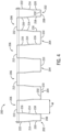
- the example second set of cross-rods 712 (or axle 802) can be spaced from the modular top plates 900 so that the second set of cross-rods 712 is lower in the pickets 800 in relation to the first set of cross-rods 706.
- a first dimension A between the center axis of the second set of cross-rods 712 and the top surface of the flatwire conveyor belt 700 is greater than a second dimension B between the center axis of the second set of cross-rods 712 and the bottom surface of the flatwire conveyor belt 700.
- first dimension A and the second dimension B are generally constrained by the first dimension A avoiding interference between the rollers 714 and the modular top plates 900, and the second dimension B accommodating sufficient material of the picket 800 to achieve the particular application requirements (e.g., fatigue strength, load-carrying capacity, etc.).
- the rollers 714 can be configured to extend beyond the bottom surface approximately 1/16" to 1/8", with a correspondingly sized gap 718.
- the interface concept disclosed establishes a flatwire conveyor belt that maintains the strength of the assembly, as the conveyor belt is placed in tension during use, and further supports top plates in such a manner as to allow the top plates to be produced from relatively thin material, thereby reducing the net conveyor belt weight.
- Other types of conveyor belts may also benefit from the incorporation of aspects of the invention.
Landscapes
- Engineering & Computer Science (AREA)
- Mechanical Engineering (AREA)
- Chain Conveyers (AREA)
Claims (6)
- Module utilisable dans un ensemble de bande transporteuse à fil plat, le module comprenant:un piquet (200) ayant des maillons avant (204) et des maillons arrière (206), le piquet (200) définissant une partie avant du piquet (200) à proximité des maillons avant (204) et une partie arrière du piquet (200) à proximité des maillons arrière (206);une plaque supérieure (300) ayant une extrémité avant (306) et une extrémité arrière (308), la plaque supérieure (300) définissant une partie avant de la plaque supérieure à proximité de l'extrémité avant (306) et une partie arrière de la plaque supérieure à proximité de l'extrémité arrière (308);dans lequel le piquet (200) et la plaque supérieure s'interfacent au niveau d'une interface avant définie par une interface entre la partie avant du piquet (200) et la partie avant de la plaque supérieure; etdans lequel le piquet (200) et la plaque supérieure (300) s'interfacent au niveau d'une interface arrière définie par une interface entre la partie arrière du piquet (200) et la partie arrière de la plaque supérieure (300),caractérisé en ce que:la partie arrière du piquet (200) comprend une fente (228);la partie arrière de la plaque supérieure comprend une languette (336); etla fente (228) et la languette (336) sont configurées pour s'interfacer lorsque la plaque supérieure (300) est positionnée sur le piquet (200).
- Module selon la revendication 1, dans lequel:la partie avant du piquet (200) comprend une ouverture (230);la partie avant de la plaque supérieure (300) comprend une oreille (324); etl'ouverture (230) et l'oreille (324) sont configurées pour s'interfacer lorsque la plaque supérieure (300) est positionnée sur le piquet (200) pour empêcher la séparation de la plaque supérieure (300) et du piquet (200).
- Module selon la revendication 1, dans lequel:la partie avant du piquet (200) comprend une ouverture (224) du piquet (200);la partie avant de la plaque supérieure (300) comprend une ouverture (322) de la plaque supérieure; etl'ouverture (224) du piquet et l'ouverture (322) de la plaque supérieure sont configurées pour s'interfacer lorsque la plaque supérieure (300) est positionnée de manière adjacente du piquet (200), de sorte qu'une tige transversale (104) peut s'étendre dans l'ouverture (224) du piquet et l'ouverture (322) de la plaque supérieure pour empêcher la séparation de la plaque supérieure (300) et du piquet (200).
- Module selon la revendication 3, comprenant en outre:une deuxième tige transversale (712) s'étendant à travers le piquet (200); etun rouleau (714) reçu sur la deuxième tige transversale (712).
- Système de bande transporteuse à fil plat (100) comprenant:un piquet (200) avec un premier ensemble d'ouvertures (224);une pluralité de plaques supérieures (300) configurées pour être fixées de manière amovible au piquet (200), chaque plaque supérieure (300) ayant une ouverture (322) pouvant être alignée avec le premier ensemble d'ouvertures (224) du piquet (200); etune tige transversale (104) reçue à travers le premier ensemble d'ouvertures (224) du piquet (200) et les ouvertures (322) des plaques supérieures (300); caractérisé en ce que:chaque plaque supérieure (300) a une extrémité arrière (308) avec une languette (336);le piquet (200) a une pluralité de parties d'extrémité arrière (212) chacune avec une fente (228); etles languettes (336) des plaques supérieures (300) peuvent être reçues de manière amovible dans les fentes (228) des parties d'extrémité arrière (212).
- Système de bande transporteuse à fil plat selon la revendication 5, dans lequel:le piquet (200) a un deuxième ensemble d'ouvertures (230);chaque plaque supérieure (300) a une oreille (324) à proximité de l'ouverture (322) de la plaque supérieure (300); etles oreilles (324) des plaques supérieures (300) peuvent être reçues de manière amovible dans le deuxième ensemble d'ouvertures (230) du piquet (200).
Applications Claiming Priority (2)
| Application Number | Priority Date | Filing Date | Title |
|---|---|---|---|
| US201862728497P | 2018-09-07 | 2018-09-07 | |
| PCT/US2019/049731 WO2020051321A1 (fr) | 2018-09-07 | 2019-09-05 | Systèmes et procédés de bande transporteuse à fil plat supérieur modulaire |
Publications (3)
| Publication Number | Publication Date |
|---|---|
| EP3847112A1 EP3847112A1 (fr) | 2021-07-14 |
| EP3847112A4 EP3847112A4 (fr) | 2022-12-14 |
| EP3847112B1 true EP3847112B1 (fr) | 2025-05-28 |
Family
ID=69720517
Family Applications (1)
| Application Number | Title | Priority Date | Filing Date |
|---|---|---|---|
| EP19856622.6A Active EP3847112B1 (fr) | 2018-09-07 | 2019-09-05 | Systèmes et procédés de bande transporteuse à fil plat supérieur modulaire |
Country Status (4)
| Country | Link |
|---|---|
| US (2) | US10858191B2 (fr) |
| EP (1) | EP3847112B1 (fr) |
| CN (1) | CN112654568B (fr) |
| WO (1) | WO2020051321A1 (fr) |
Families Citing this family (3)
| Publication number | Priority date | Publication date | Assignee | Title |
|---|---|---|---|---|
| USD916415S1 (en) * | 2012-01-12 | 2021-04-13 | MoveRoll Oy | Paper roll conveyor module |
| US10858191B2 (en) * | 2018-09-07 | 2020-12-08 | Cambridge International, Inc. | Modular top flatwire conveyor belt systems and methods |
| CN112703161B (zh) | 2018-09-21 | 2025-08-22 | 莱克斯诺弗莱托普欧洲有限公司 | 用于物品输送机的链条的链节 |
Family Cites Families (31)
| Publication number | Priority date | Publication date | Assignee | Title |
|---|---|---|---|---|
| US1354553A (en) * | 1919-06-28 | 1920-10-05 | Cyclone Fence Company | Belt conveyer |
| US2621779A (en) * | 1949-11-23 | 1952-12-16 | United States Steel Corp | Flat wire conveyer belt and cover plate therefor |
| US3045809A (en) * | 1959-07-07 | 1962-07-24 | Ashworth Bros Inc | Cover plate for flat wire conveyor belt |
| US3520398A (en) * | 1967-11-30 | 1970-07-14 | Rex Chainbelt Inc | Laterally flexible conveyor |
| US3863754A (en) * | 1972-10-24 | 1975-02-04 | United States Steel Corp | Flat wire conveyor belt with improved covering |
| US3876547A (en) * | 1973-08-01 | 1975-04-08 | Clarkson Ind Inc | Butterfly conveyor clip for flat bed filter |
| US3977514A (en) * | 1973-08-01 | 1976-08-31 | Clarkson Industries, Inc. | Butterfly conveyor clip for flat bed filter |
| GB2077685B (en) | 1979-07-18 | 1983-03-09 | Henrekson Ulf | Conveyor |
| JPS59179806U (ja) | 1983-05-19 | 1984-12-01 | 株式会社椿本チエイン | ヒンジ型テ−ブルトツプチエ−ン |
| US5042244A (en) | 1990-05-21 | 1991-08-27 | Drives-Incorporated | Roof top chain |
| US6347699B1 (en) | 1999-11-08 | 2002-02-19 | Earl Ramsey | Conveyor chain link |
| US6854590B2 (en) | 2001-07-24 | 2005-02-15 | Fmc Technologies, Inc. | Conveyor belt assembly |
| US6851549B1 (en) | 2003-08-28 | 2005-02-08 | Bernie Beringer | Product capturing chain construction |
| US6945388B2 (en) | 2004-02-02 | 2005-09-20 | Rexnord Industries, Inc. | Anti-shingling product conveying chain |
| US7428694B2 (en) | 2004-03-02 | 2008-09-23 | Stmicroelectronics S.A. | Device for protection against error injection into a synchronous flip-flop of an elementary logic module |
| DE102004021262A1 (de) | 2004-04-30 | 2005-11-17 | Sander Hansen A/S | Pasteur mit Förderband |
| NL1026284C2 (nl) * | 2004-05-27 | 2005-11-30 | Rexnord Flattop Europe Bv | Samenstel voor het scharnierbaar koppelen van delen van een transporteur, alsmede scharnierpen. |
| US7494005B2 (en) | 2005-09-30 | 2009-02-24 | Cambridge International, Inc. | Variable spaced conveyor belt |
| US7556142B2 (en) | 2005-11-30 | 2009-07-07 | Rexnord Industries, Llc | Conveyor plate with integrated roller |
| US7364036B2 (en) * | 2006-02-09 | 2008-04-29 | Habasit Ag | Module for a perforated flat top belt with hinge gap for better fluid flow |
| ITMI20060050U1 (it) | 2006-02-10 | 2007-08-11 | Regina Sud Spa | Maglia di catena metallica per trasportatore a catena con struttura perfezionata |
| NL2005790C2 (nl) * | 2010-11-30 | 2012-05-31 | Rexnord Flattop Europe Bv | Modulaire transportmat en module daarvoor. |
| US9061829B2 (en) | 2011-10-26 | 2015-06-23 | Cambridge International, Inc. | Conveyor belt with improved edge configuration |
| BR112014013703B1 (pt) * | 2011-12-06 | 2021-01-12 | Ashworth Brothers, Inc | esteiras transportadoras e métodos de montagem de uma esteira transportadora |
| SE1250273A1 (sv) | 2012-03-20 | 2013-09-21 | Flexlink Components Ab | Transportkedjelänk och transportkedja |
| US9856087B2 (en) | 2013-04-16 | 2018-01-02 | Illinois Tool Works Inc. | Conveyor belt and platform for conveyor belt |
| SE538966C2 (sv) | 2013-05-24 | 2017-03-07 | Carryline Ab | Transportkedja & transportkedjesystem |
| KR101561435B1 (ko) | 2014-11-19 | 2015-10-20 | 이동덕 | 컨베이어용 링크체인 |
| EP3070029A1 (fr) | 2015-03-19 | 2016-09-21 | Cambridge International, Inc. | Système de bande transporteuse à capteur intégré et son procédé d'utilisation |
| US10183809B2 (en) | 2016-05-24 | 2019-01-22 | Habasit Ag | Pin retention for conveyor modules |
| US10858191B2 (en) * | 2018-09-07 | 2020-12-08 | Cambridge International, Inc. | Modular top flatwire conveyor belt systems and methods |
-
2019
- 2019-09-05 US US16/561,563 patent/US10858191B2/en active Active
- 2019-09-05 EP EP19856622.6A patent/EP3847112B1/fr active Active
- 2019-09-05 WO PCT/US2019/049731 patent/WO2020051321A1/fr not_active Ceased
- 2019-09-05 CN CN201980058589.1A patent/CN112654568B/zh active Active
-
2020
- 2020-11-05 US US17/090,159 patent/US11465852B2/en active Active
Also Published As
| Publication number | Publication date |
|---|---|
| WO2020051321A1 (fr) | 2020-03-12 |
| US11465852B2 (en) | 2022-10-11 |
| CN112654568B (zh) | 2023-11-21 |
| EP3847112A1 (fr) | 2021-07-14 |
| US20210053762A1 (en) | 2021-02-25 |
| CN112654568A (zh) | 2021-04-13 |
| US10858191B2 (en) | 2020-12-08 |
| EP3847112A4 (fr) | 2022-12-14 |
| US20200079592A1 (en) | 2020-03-12 |
Similar Documents
| Publication | Publication Date | Title |
|---|---|---|
| US11465852B2 (en) | Modular top flatwire conveyor belt systems and methods | |
| US4880107A (en) | Table top chain link with rib | |
| US4645070A (en) | Dual bend conveyor | |
| JP4010755B2 (ja) | コンベヤチェーン | |
| EP2509895B1 (fr) | Système de transfert par convoyeur doté d'une plate-forme de transfert flottante | |
| US7559422B2 (en) | Modular link or link section for use in forming a rodless conveyor belt | |
| EP1647515B1 (fr) | Bande transporteuse antidérapant modulaire en matière plastique | |
| EP4217297A1 (fr) | Bloqueur d'espace de transporteur à rouleaux | |
| EP0705776A1 (fr) | Plateau de transfert tendu pour convoyeur à chaîne à petit pas | |
| JPH08239117A (ja) | 交差コンベヤ間で物品を移送するための方向変更機構 | |
| CA2140419A1 (fr) | Courroie transporteuse a courbure horizontale | |
| EP3015405B1 (fr) | Courroie transporteuse et maillon de chaîne | |
| US6105755A (en) | Curved conveyor section | |
| CN108025872B (zh) | 带有偏置轴承的传送带组件 | |
| EP1404597A1 (fr) | Raccord comprenant un element de protection lateral tordu | |
| JP3772626B2 (ja) | コンベヤ間の受渡部材 | |
| JP2022529906A (ja) | コンベヤ用のモジュール式ノーズローラアセンブリ | |
| MXPA05011824A (es) | Ensamble de transportacion modular de baja presion de retroceso. | |
| US7650983B2 (en) | Member for removably connecting at least one vertical guide and slide wall above a conveyor, the vertical guide and slide wall, and guide and slide means for said wall | |
| US9139370B1 (en) | Conveyor system and a mechanical chain having a plurality of links | |
| US10502288B2 (en) | Chain drive device and chain guide | |
| JP3726159B2 (ja) | スラットバンドチェーン | |
| NL1032314C2 (nl) | Kettingmodule voor een modulaire kettingtransporteur, modulaire transporteur en transportsysteem voorzien van een modulaire kettingtransporteur. |
Legal Events
| Date | Code | Title | Description |
|---|---|---|---|
| STAA | Information on the status of an ep patent application or granted ep patent |
Free format text: STATUS: THE INTERNATIONAL PUBLICATION HAS BEEN MADE |
|
| PUAI | Public reference made under article 153(3) epc to a published international application that has entered the european phase |
Free format text: ORIGINAL CODE: 0009012 |
|
| STAA | Information on the status of an ep patent application or granted ep patent |
Free format text: STATUS: REQUEST FOR EXAMINATION WAS MADE |
|
| 17P | Request for examination filed |
Effective date: 20210308 |
|
| AK | Designated contracting states |
Kind code of ref document: A1 Designated state(s): AL AT BE BG CH CY CZ DE DK EE ES FI FR GB GR HR HU IE IS IT LI LT LU LV MC MK MT NL NO PL PT RO RS SE SI SK SM TR |
|
| DAV | Request for validation of the european patent (deleted) | ||
| DAX | Request for extension of the european patent (deleted) | ||
| REG | Reference to a national code |
Ref country code: DE Ref legal event code: R079 Free format text: PREVIOUS MAIN CLASS: B65G0015540000 Ipc: B65G0017060000 Ref country code: DE Ref legal event code: R079 Ref document number: 602019070610 Country of ref document: DE Free format text: PREVIOUS MAIN CLASS: B65G0015540000 Ipc: B65G0017060000 |
|
| A4 | Supplementary search report drawn up and despatched |
Effective date: 20221111 |
|
| RIC1 | Information provided on ipc code assigned before grant |
Ipc: B65G 17/44 20060101ALI20221107BHEP Ipc: B65G 17/08 20060101ALI20221107BHEP Ipc: B65G 17/06 20060101AFI20221107BHEP |
|
| P01 | Opt-out of the competence of the unified patent court (upc) registered |
Effective date: 20230525 |
|
| GRAP | Despatch of communication of intention to grant a patent |
Free format text: ORIGINAL CODE: EPIDOSNIGR1 |
|
| STAA | Information on the status of an ep patent application or granted ep patent |
Free format text: STATUS: GRANT OF PATENT IS INTENDED |
|
| INTG | Intention to grant announced |
Effective date: 20241223 |
|
| GRAS | Grant fee paid |
Free format text: ORIGINAL CODE: EPIDOSNIGR3 |
|
| GRAA | (expected) grant |
Free format text: ORIGINAL CODE: 0009210 |
|
| STAA | Information on the status of an ep patent application or granted ep patent |
Free format text: STATUS: THE PATENT HAS BEEN GRANTED |
|
| AK | Designated contracting states |
Kind code of ref document: B1 Designated state(s): AL AT BE BG CH CY CZ DE DK EE ES FI FR GB GR HR HU IE IS IT LI LT LU LV MC MK MT NL NO PL PT RO RS SE SI SK SM TR |
|
| REG | Reference to a national code |
Ref country code: GB Ref legal event code: FG4D |
|
| REG | Reference to a national code |
Ref country code: CH Ref legal event code: EP |
|
| REG | Reference to a national code |
Ref country code: IE Ref legal event code: FG4D Ref country code: DE Ref legal event code: R096 Ref document number: 602019070610 Country of ref document: DE |
|
| REG | Reference to a national code |
Ref country code: NL Ref legal event code: FP |
|
| PG25 | Lapsed in a contracting state [announced via postgrant information from national office to epo] |
Ref country code: FI Free format text: LAPSE BECAUSE OF FAILURE TO SUBMIT A TRANSLATION OF THE DESCRIPTION OR TO PAY THE FEE WITHIN THE PRESCRIBED TIME-LIMIT Effective date: 20250528 Ref country code: ES Free format text: LAPSE BECAUSE OF FAILURE TO SUBMIT A TRANSLATION OF THE DESCRIPTION OR TO PAY THE FEE WITHIN THE PRESCRIBED TIME-LIMIT Effective date: 20250528 |
|
| REG | Reference to a national code |
Ref country code: LT Ref legal event code: MG9D |
|
| PG25 | Lapsed in a contracting state [announced via postgrant information from national office to epo] |
Ref country code: NO Free format text: LAPSE BECAUSE OF FAILURE TO SUBMIT A TRANSLATION OF THE DESCRIPTION OR TO PAY THE FEE WITHIN THE PRESCRIBED TIME-LIMIT Effective date: 20250828 Ref country code: GR Free format text: LAPSE BECAUSE OF FAILURE TO SUBMIT A TRANSLATION OF THE DESCRIPTION OR TO PAY THE FEE WITHIN THE PRESCRIBED TIME-LIMIT Effective date: 20250829 |
|
| PG25 | Lapsed in a contracting state [announced via postgrant information from national office to epo] |
Ref country code: PL Free format text: LAPSE BECAUSE OF FAILURE TO SUBMIT A TRANSLATION OF THE DESCRIPTION OR TO PAY THE FEE WITHIN THE PRESCRIBED TIME-LIMIT Effective date: 20250528 |
|
| PG25 | Lapsed in a contracting state [announced via postgrant information from national office to epo] |
Ref country code: BG Free format text: LAPSE BECAUSE OF FAILURE TO SUBMIT A TRANSLATION OF THE DESCRIPTION OR TO PAY THE FEE WITHIN THE PRESCRIBED TIME-LIMIT Effective date: 20250528 |
|
| PG25 | Lapsed in a contracting state [announced via postgrant information from national office to epo] |
Ref country code: HR Free format text: LAPSE BECAUSE OF FAILURE TO SUBMIT A TRANSLATION OF THE DESCRIPTION OR TO PAY THE FEE WITHIN THE PRESCRIBED TIME-LIMIT Effective date: 20250528 |
|
| PG25 | Lapsed in a contracting state [announced via postgrant information from national office to epo] |
Ref country code: RS Free format text: LAPSE BECAUSE OF FAILURE TO SUBMIT A TRANSLATION OF THE DESCRIPTION OR TO PAY THE FEE WITHIN THE PRESCRIBED TIME-LIMIT Effective date: 20250828 |
|
| PG25 | Lapsed in a contracting state [announced via postgrant information from national office to epo] |
Ref country code: IS Free format text: LAPSE BECAUSE OF FAILURE TO SUBMIT A TRANSLATION OF THE DESCRIPTION OR TO PAY THE FEE WITHIN THE PRESCRIBED TIME-LIMIT Effective date: 20250928 |
|
| PG25 | Lapsed in a contracting state [announced via postgrant information from national office to epo] |
Ref country code: LV Free format text: LAPSE BECAUSE OF FAILURE TO SUBMIT A TRANSLATION OF THE DESCRIPTION OR TO PAY THE FEE WITHIN THE PRESCRIBED TIME-LIMIT Effective date: 20250528 |
|
| REG | Reference to a national code |
Ref country code: AT Ref legal event code: MK05 Ref document number: 1798533 Country of ref document: AT Kind code of ref document: T Effective date: 20250528 |
|
| PG25 | Lapsed in a contracting state [announced via postgrant information from national office to epo] |
Ref country code: SM Free format text: LAPSE BECAUSE OF FAILURE TO SUBMIT A TRANSLATION OF THE DESCRIPTION OR TO PAY THE FEE WITHIN THE PRESCRIBED TIME-LIMIT Effective date: 20250528 Ref country code: DK Free format text: LAPSE BECAUSE OF FAILURE TO SUBMIT A TRANSLATION OF THE DESCRIPTION OR TO PAY THE FEE WITHIN THE PRESCRIBED TIME-LIMIT Effective date: 20250528 Ref country code: AT Free format text: LAPSE BECAUSE OF FAILURE TO SUBMIT A TRANSLATION OF THE DESCRIPTION OR TO PAY THE FEE WITHIN THE PRESCRIBED TIME-LIMIT Effective date: 20250528 |
|
| PG25 | Lapsed in a contracting state [announced via postgrant information from national office to epo] |
Ref country code: CZ Free format text: LAPSE BECAUSE OF FAILURE TO SUBMIT A TRANSLATION OF THE DESCRIPTION OR TO PAY THE FEE WITHIN THE PRESCRIBED TIME-LIMIT Effective date: 20250528 |
|
| PG25 | Lapsed in a contracting state [announced via postgrant information from national office to epo] |
Ref country code: EE Free format text: LAPSE BECAUSE OF FAILURE TO SUBMIT A TRANSLATION OF THE DESCRIPTION OR TO PAY THE FEE WITHIN THE PRESCRIBED TIME-LIMIT Effective date: 20250528 |
|
| PG25 | Lapsed in a contracting state [announced via postgrant information from national office to epo] |
Ref country code: RO Free format text: LAPSE BECAUSE OF FAILURE TO SUBMIT A TRANSLATION OF THE DESCRIPTION OR TO PAY THE FEE WITHIN THE PRESCRIBED TIME-LIMIT Effective date: 20250528 Ref country code: SK Free format text: LAPSE BECAUSE OF FAILURE TO SUBMIT A TRANSLATION OF THE DESCRIPTION OR TO PAY THE FEE WITHIN THE PRESCRIBED TIME-LIMIT Effective date: 20250528 |
|
| PG25 | Lapsed in a contracting state [announced via postgrant information from national office to epo] |
Ref country code: IT Free format text: LAPSE BECAUSE OF FAILURE TO SUBMIT A TRANSLATION OF THE DESCRIPTION OR TO PAY THE FEE WITHIN THE PRESCRIBED TIME-LIMIT Effective date: 20250528 |