EP3847063B1 - Führungshülse zum führen einer manschette eines relaisventils für einen elektropneumatischen modulator - Google Patents
Führungshülse zum führen einer manschette eines relaisventils für einen elektropneumatischen modulator Download PDFInfo
- Publication number
- EP3847063B1 EP3847063B1 EP19756121.0A EP19756121A EP3847063B1 EP 3847063 B1 EP3847063 B1 EP 3847063B1 EP 19756121 A EP19756121 A EP 19756121A EP 3847063 B1 EP3847063 B1 EP 3847063B1
- Authority
- EP
- European Patent Office
- Prior art keywords
- section
- guide sleeve
- guide
- housing
- sleeve
- Prior art date
- Legal status (The legal status is an assumption and is not a legal conclusion. Google has not performed a legal analysis and makes no representation as to the accuracy of the status listed.)
- Active
Links
Images


Classifications
-
- B—PERFORMING OPERATIONS; TRANSPORTING
- B60—VEHICLES IN GENERAL
- B60T—VEHICLE BRAKE CONTROL SYSTEMS OR PARTS THEREOF; BRAKE CONTROL SYSTEMS OR PARTS THEREOF, IN GENERAL; ARRANGEMENT OF BRAKING ELEMENTS ON VEHICLES IN GENERAL; PORTABLE DEVICES FOR PREVENTING UNWANTED MOVEMENT OF VEHICLES; VEHICLE MODIFICATIONS TO FACILITATE COOLING OF BRAKES
- B60T15/00—Construction arrangement, or operation of valves incorporated in power brake systems and not covered by groups B60T11/00 or B60T13/00
- B60T15/02—Application and release valves
- B60T15/025—Electrically controlled valves
- B60T15/027—Electrically controlled valves in pneumatic systems
-
- F—MECHANICAL ENGINEERING; LIGHTING; HEATING; WEAPONS; BLASTING
- F16—ENGINEERING ELEMENTS AND UNITS; GENERAL MEASURES FOR PRODUCING AND MAINTAINING EFFECTIVE FUNCTIONING OF MACHINES OR INSTALLATIONS; THERMAL INSULATION IN GENERAL
- F16K—VALVES; TAPS; COCKS; ACTUATING-FLOATS; DEVICES FOR VENTING OR AERATING
- F16K31/00—Actuating devices; Operating means; Releasing devices
- F16K31/12—Actuating devices; Operating means; Releasing devices actuated by fluid
- F16K31/42—Actuating devices; Operating means; Releasing devices actuated by fluid by means of electrically-actuated members in the supply or discharge conduits of the fluid motor
Definitions
- the present approach relates to a guide sleeve for guiding a sleeve of a relay valve for an electropneumatic modulator for a braking system for a vehicle, a guide sleeve device with a guide sleeve, a relay valve with a guide sleeve device and a method for manufacturing a relay valve.
- relay valves in which a collar of the relay valve is guided on two hollow cylinders that are formed by a plastic part such as a guide sleeve. Assembly of a sealing element and the boot and alignment is done by an assembly tool from a top side of a module of a two-piece housing. The guide sleeve is fastened in the housing by means of a retaining ring in the housing.
- the WO 2015/058828 A1 describes a relay valve for a compressed air system, a valve device with the relay valve and a vehicle with the relay valve and/or with the valve device.
- the EP 2 266 854 A2 describes a relay valve, a silencer, a valve device and a vehicle.
- the ES 1 033 579 U describes a trolley for transporting objects.
- DE 29 18 032 A1 describes a relay valve for pressurized brake systems on motor vehicles and trailers.
- the EP 2 407 355 A1 describes a relay valve and a method of operating a relay valve.
- the object of the present approach is an improved guide sleeve for guiding a collar of a relay valve for an electropneumatic modulator for a brake system for a vehicle, a guide sleeve device with an improved guide sleeve, a relay valve to provide an improved guide sleeve device and a method of making an improved relay valve.
- a guide sleeve for guiding a collar of a relay valve for an electropneumatic modulator for a vehicle brake system, a guide sleeve device with a guide sleeve, a relay valve with a guide sleeve device and a method for manufacturing a relay valve according to the main claims.
- a guide sleeve for a relay valve is created, which is shaped both to guide a sleeve that can be moved by a relay piston and to be securely and easily fastened in a housing of the relay valve.
- a guide sleeve presented here is also advantageously formed for use with and for assembly in a one-piece housing of the relay valve.
- a guide sleeve for guiding a sleeve of a relay valve for an electropneumatic modulator for a brake system for a vehicle comprises a guide section and a holding section.
- the guide section is formed such that it can be coupled to or in a counter-guide section of the collar of the relay valve in order to enable the collar to be guided along the guide section.
- the holding section is formed in order to fasten the guide sleeve in a form-fitting manner in a housing of the relay valve.
- the boot In an operative state of the relay valve, the boot may be shaped and arranged to close an opening of the relay valve.
- the collar By moving a relay piston of the relay valve against the collar, the collar can be moved along the guide portion of the guide sleeve to open the relay valve.
- the collar can be arranged between the relay piston and the guide sleeve when the relay valve is in the operational state.
- a collar spring can be clamped between the collar and the guide sleeve, which spring is designed to cause the relay valve to close when the relay piston is arranged at a distance from the collar.
- the guide sleeve itself can also serve as a closure of the relay valve.
- the holding section can be formed, for example, in order to fasten the guide sleeve in a form-fitting manner in an undercut of the housing of the relay valve.
- an outer diameter of the holding section can be larger than an outer diameter of the guide section, for example more than twice as large.
- a guide sleeve presented here advantageously enables a double function of a guide sleeve, whereby on the one hand the cuff can be guided in a centered manner along the guide sleeve and on the other hand the guide sleeve can be fastened in the housing.
- the holding section forms at least one latching hook and additionally or alternatively a bayonet.
- Such a latching hook and additionally or alternatively a bayonet will latch or snap into the housing, for example in the undercut of the housing, in order to enable a secure connection.
- the latching hook and additionally or alternatively the bayonet can be shaped to prevent the guide sleeve from sliding out counter to a direction of insertion of the guide sleeve into the housing when the guide sleeve is installed. Stable attachment in a tubular housing can thus be made possible.
- the latching hook enables a permanent or non-detachable connection, while the bayonet can enable a detachable connection.
- the guide section and the holding section extend to two opposite sides of the guide sleeve.
- the guide section and the holding section can be formed on two opposite ends of the guide sleeve.
- the collar and the relay piston can thus be guided to one side of the guide sleeve and the relay valve can be closed by the retaining section on the opposite side.
- the guide sleeve forms a middle section which is arranged between the guide section and the holding section and which can be formed essentially in the shape of a circular ring or a hollow truncated cone.
- This middle section can be used to connect the guide section to the holding section.
- the central section can extend essentially perpendicularly to an axis of extent of the guide section or can extend obliquely away from the guide section.
- the housing or the relay valve can thus be closed by the middle section.
- the middle section forms the shape of a hollow truncated cone or a funnel, this can create a space in the truncated cone or funnel.
- This space can be formed between the guide sleeve and a silencer which is or can be arranged opposite the sleeve, so that air can expand in the space before it flows out through the silencer.
- the holding section can be formed on an underside of the central section and additionally or alternatively the guide section can be formed on an upper side of the central section opposite the underside.
- the holding section can extend from an edge section of the underside of the central section and, additionally or alternatively, the guide section can extend away from a substantially central area of the upper side of the central section. This enables the guide sleeve to be fastened to an inner wall of the housing and allows the sleeve to be guided in a centered manner.
- the guide sleeve has at least one axial rib that extends away from an underside of the central section facing the holding section and additionally or alternatively has an axis of extension that runs parallel to the guide section.
- This axial rib can be rod-shaped.
- Such an axial rib can be formed to protrude into or press into the silencer when the relay valve is in the operational state with a silencer, in order to increase the stability of the guide sleeve and additionally or alternatively to allow air to flow in the space to the housing to reduce.
- the guide sleeve can also have a plurality of such axial ribs, which can be arranged in a ring shape.
- the guide sleeve can have at least one radial rib, which can extend radially between a sleeve passage opening of the guide sleeve and the holding section on an underside of the central section facing the holding section.
- a radial rib can advantageously reduce air vortices that arise in the space.
- the guide sleeve can also have a plurality of such radial ribs, which can be arranged running radially around the sleeve passage opening.
- the guide section can form an outer sleeve and an inner sleeve surrounded by the outer sleeve, it being possible for the inner sleeve to comprise a sleeve passage opening of the guide sleeve. So they can Outer sleeve and additionally or alternatively the inner sleeve are plugged or inserted into the mating guide section of the cuff when coupling with the cuff.
- the counter-guide section can be shaped similarly to the guide section.
- the guide sleeve is formed in one piece and, additionally or alternatively, is funnel-shaped overall.
- Such a one-piece guide sleeve can be easily produced by injection molding, for example, and requires little material and costs in production.
- a guide sleeve device has a guide sleeve in one of the variants presented above and the cuff, with an inner diameter of the cuff being equal to or smaller than an inner diameter of the guide section of the guide sleeve.
- Such a guide sleeve device can advantageously be installed together from one side into the housing during assembly using a single assembly tool and a single assembly step due to the mutually matched inner diameters of the guide section and the sleeve. This is particularly advantageous if the housing of the relay valve is formed in one piece and the relay valve components that can be arranged in a receiving chamber of the housing are stacked one after the other from one side into the receiving chamber when the relay valve is assembled.
- the mating guide portion of the cuff and the guiding portion may be shaped to seal a gap between the mating guide portion and the guiding portion.
- one end of the counter-guiding section can form a sealing element which, in the coupled state of the guiding section on or in the counter-guiding section, can bear against the guiding section and, additionally or alternatively, in the coupled state of the guiding section on or in the counter-guiding section there can be close contact.
- a relay valve has a housing, a guide sleeve device which can be arranged or is arranged in the housing and is formed in one of the variants presented above, and a relay piston which can be arranged or is arranged in the housing for moving the sleeve along the guide section of the guide sleeve on.
- the housing can be molded in one piece.
- the relay plunger and the guide sleeve device may be recessed or housed in an accommodating chamber of the relay plunger.
- a method of manufacturing a relay valve includes a providing step, an inserting step, and an inserting step.
- a housing, a relay piston and a guide sleeve device are provided, which is formed in one of the variants presented above.
- the relay piston is inserted into the housing.
- the guide sleeve device is inserted into the housing, with the guide sleeve device being inserted into the housing in such a way that the guide section of the guide sleeve is coupled to the counter-guide section of the sleeve and the holding section of the guide sleeve is fastened in the housing with a form fit by the holding section in engages or snaps into an undercut of the housing.
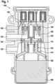
- FIG. 1 shows a schematic cross-sectional side view of an electropneumatic modulator 100 with a relay valve 105 with a guide sleeve 110 for guiding a collar 115 of the relay valve 105 according to an embodiment.
- Electropneumatic modulator 100 is designed for use in an electropneumatic brake system for a vehicle and, in an operational state shown here, is designed to regulate a pneumatic brake pressure, ie compressed air, that is provided when the vehicle brakes.
- a pneumatic brake pressure ie compressed air
- the relay valve 105 is part of the electropneumatic modulator 100.
- the relay valve 105 comprises a housing 120, a guide sleeve device 125 which can be arranged or is arranged in the housing 120 and a relay piston 130 which can be arranged or is arranged in the housing 120.
- the guide sleeve device 125 comprises the Guide sleeve 110 and the sleeve 115.
- the relay valve 105 is arranged in an operative state in which the relay piston 130 and the guide sleeve device 125 are accommodated in the housing 120.
- the sleeve 115 is arranged between the relay piston 130 and the guide sleeve 110 .
- the electropneumatic modulator 100 is part of the vehicle's braking system.
- the brake system includes a reservoir for providing compressed air, a control device for providing an electrical control signal, a foot brake device for providing a pneumatic control signal, and/or a wheel brake device for braking a wheel of the vehicle.
- the functionality of the modulator 100 corresponds to the functionality of known electropneumatic modulators used in connection with brake systems.
- the electropneumatic modulator 100 has an electrical control input for receiving the electrical control signal from the control device, a reservoir connection 135 for supplying the compressed air from the reservoir, a pneumatic control input 140 for supplying the compressed air from the reservoir in response to the pneumatic control signal, and a brake output 145 for outputting a brake pressure to the wheel brake device.
- the wheel brake device can be designed in accordance with a brake that is customary in the vehicle sector, and can include, for example, a brake cylinder that can be actuated by the brake pressure.
- the electrical control signal represents an electrical signal.
- the electrical control signal can indicate a requested target brake pressure.
- the control device is embodied as a brake control device, for example, and the electropneumatic modulator 100 includes, for example, at least one solenoid valve that can be actuated using the electrical control signal or a signal generated in response to receipt of the electrical control signal.
- the relay piston 130 and the guide sleeve device 125 are accommodated one above the other in an accommodating chamber 150 of the housing 120 .
- the brake outlet 145 and the supply port 135 open into the receiving chamber 150.
- the relay valve 105 is designed and shaped to establish a fluidic connection between the supply port 135 and to open or close the brake output 145 by moving the relay piston 130 .
- the receiving chamber 150 includes a control chamber section, which can be acted upon by supplied compressed air, controlled by the electrical control signal, in order to bring about a switching movement of the relay piston 130 .
- receiving chamber 150 also includes a working chamber section that is fluidically connected to brake outlet 145 and can be acted upon by the switching movement of relay piston 130 with compressed air supplied via supply port 135 in order to provide the brake pressure at brake outlet 145.
- the guide sleeve 110 presented here is accommodated in or on the relay valve 105 .
- the guide sleeve 110 is shaped to guide the sleeve 115 of the relay valve 105 and/or to fasten it in the housing 120 .
- the guide sleeve 110 comprises a guide section 155 and a holding section 160.
- the guide section 155 is formed such that it can be coupled to or in a counter-guide section of the collar 115 of the relay valve 105 in order to enable the collar 115 to be guided along the guide section 110.
- a cuff spring is clamped between the cuff and the guide section 110 .
- the holding section 160 is formed in order to fasten the guide sleeve 110 in the housing 120 of the relay valve 105 in a form-fitting manner.
- relay valve 105 is arranged in a ready-to-operate state in which guide section 155 of guide sleeve 110 is arranged coupled to or in the counter-guide section of sleeve 115 and holding section 160 of guide sleeve 110 is positively secured in housing 120.
- the relay valve 105 is arranged in a closed state in which the supply connection 135 and the brake outlet 145 are not fluidly connected to one another.
- the relay piston 130 is arranged at a distance from the sleeve 115 and thus does not move it along the guide section 155.
- the relay piston 130 of the relay valve 105 is designed to move the collar 115 along the guide portion 155 of the guide sleeve 110 to cause the relay valve 105 to open.
- a silencer 165 is arranged on a side of the guide sleeve 110 facing the holding section 160 .
- the muffler 165 is part of the relay valve 105 and/or at least partially arranged in the housing 120 .
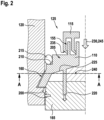
- FIG. 2 12 shows a detail of a lateral cross-sectional view of a guide sleeve device 125 according to an exemplary embodiment.
- This can be the in 1 act described guide sleeve device 125, in which the guide sleeve 110 and the sleeve 115 are coupled to each other.
- the housing 120 can also be the in 1 Housing 120 described and the silencer 165 can be the one in 1 act described silencer 165. is shown in 2 only one of two halves of the cross-section. A non-illustrated other half can be formed in accordance with the half shown here.
- the holding section 160 forms at least one latching hook or, according to an alternative exemplary embodiment, a bayonet. According to one exemplary embodiment, this latching hook latches into an undercut of the housing 120 . According to this exemplary embodiment, the latching hook, which can also be referred to as a lateral snapping rib, causes a radial compression of the muffler 165 or, to put it another way, a radial external compression 200 on the muffler 165.
- the guide section 155 and the holding section 160 extend to two opposite sides of the guide sleeve 110.
- An axis of extension of the guide section 155 runs parallel to an intended axis of movement of the relay piston and/or an axis of extension of an inner wall of the housing 120.
- An axis of extension of the holding section 160 in the form of the latching hook is arranged to run obliquely to the axis of extent of the guide section 155 .
- the holding section 160 forms the guide sleeve 110 from a central section 205 which is formed essentially in the shape of a circular ring or a hollow truncated cone.
- the middle section 205 is formed in the shape of a circular ring, in 1 an embodiment of the central section 205 in the form of a truncated hollow cone is shown.
- holding section 160 extends from an underside of central section 205 and guide section 155 from an upper side of central section 205 arranged opposite the underside.
- holding section 160 extends from an outer edge section of the underside and/or guide section 155 from a substantially central area of the top.
- the middle section 205 has a step 210 between the upper side and the edge section, in which a sealing element 215 is accommodated, which is shaped to seal the guide sleeve 110 against the housing 120 .
- the sealing element 215 is a sealing ring which is arranged in a circumferential step 210 .
- the guide sleeve 110 has at least one axial rib 220 which extends away from the underside of the middle section 205 facing the holding section 160 .
- an extension axis of the axial rib 220 is arranged to run parallel to the guide section 155 .
- a length of extension of the axial rib 220 is longer than a length of extension of the latching hook.
- the axial rib 220 extends away from a central area of a radius of the central section 205 and/or enables an axial pressing into the muffler 165.
- the guide sleeve 110 has at least one radial rib 225 which extends radially on the underside of the central section 205 between a sleeve passage opening 230 in the guide sleeve 110 and the holding section 160 .
- the radial rib 225 runs obliquely or in a wedge shape from the sleeve passage opening 230 to the holding section 160 .
- the axial rib 220 is arranged on the radial rib 225 .
- the guide section 155 forms an outer sleeve and an inner sleeve surrounded by the outer sleeve, the inner sleeve encompassing the sleeve passage opening 230 of the guide sleeve 110 .
- an inner diameter of the sleeve 115 is the same as or, according to an alternative exemplary embodiment, smaller than an inner diameter of the guide section 155 of the guide sleeve 110.
- the counter-guide section 235 of the sleeve 115 and the guide section 155 are formed in order to avoid a gap between the counter-guide section 235 and the guide portion 155 to seal.
- the counter-guide section 235 rests against or in an outer wall of the inner sleeve and the outer sleeve.
- the guide sleeve 110 is formed in one piece and/or in the form of a funnel overall.
- the guide sleeve 110 presented here can also be referred to as a guide sleeve 110 with snap geometry.
- One task of the guide sleeve 110 is to form the guide for the cuff 115 .
- the guide sleeve device 125 realizes sleeve and guide sleeve inner diameters that are adapted to one another.
- An assembly of the guide sleeve device 125 is now advantageously possible from below in the housing 120, since the sleeve 115 can be aligned on the guide sleeve 110 using an assembly tool; see also the assembly tool in FIG 4 .
- Such an assembly from below is a basic requirement for a housing 120 that is closed in an upper area, according to this exemplary embodiment a one-piece housing 120 that contributes to cost savings.
- Another task of the guide sleeve 110 is to absorb pneumatic forces and form a closed pressure area.
- the latching of the snap-in geometry of the guide sleeve 110 in the housing 120 advantageously makes it possible to save an additional securing ring and, in addition, there is advantageously a very low outlay on assembly.
- the latching hook is latched in the housing 120 in a non-detachable manner. Another advantage is that no impermissible replacement parts can be installed since it is not possible to remove the guide sleeve 110 without destroying it.
- a further task of the guide sleeve 110 is to guide air to the silencer 165 during venting.
- This object is achieved by the guide sleeve 165 in that a space 240 is created above the fabric of the muffler 165 in which the air can expand before it flows out of the muffler 165 .
- the lateral ribs in the form of radial ribs 225 in this space 240 ensure that air turbulence that occurs is reduced.
- the retaining section 160 in the form of lateral snap-in ribs causes the radial compression 200 of the knitted fabric and thus the air flowing between the housing 120 and the sound absorber 165 is effectively prevented.
- an axial compression rib acts in the form of the axial rib 220 , which reduces an air flow 245 in the direction of the housing 120 .
- An assembly of the guide sleeve device 125 and/or an alignment is advantageously made possible by a single assembly tool from a lower side of the housing 120 .
- the relay valve or even the entire electro-pneumatic modulator can thus advantageously be arranged or mounted in a one-piece housing 120, see also 1 . Additional components such as a locking ring for fastening the guide sleeve 110 or the entire relay valve in the housing 120 are advantageously not necessary thanks to the holding section 160 .
- the space 240 is created according to this exemplary embodiment between the underside of the middle section 205 and the silencer 165, which allows damping of an air flow 245 flowing through the sleeve through-opening 230 to the silencer 165.
- An additional damping plate with holes between the guide sleeve 110 and the silencer 165 is therefore not necessary necessary.
- such a damping plate with holes is nevertheless arranged between the guide sleeve 110 and the silencer 165 in order to bring about even greater damping of the air flow 245 .
- an additional compression of the fabric of the muffler 165 is realized by a further step in the housing 120 .
- an inner diameter of the guide sleeve 110 is also reinforced with ribs and/or webs, with a slotted assembly tool being able to be used for assembly.
- a sleeve which, according to an alternative exemplary embodiment, has a smaller inner diameter than the guide sleeve 110 can be centered with a step-shaped assembly tool.
- the space 240 is at least partially formed by the housing 120 in the form of a cast housing itself.
- FIG 3 shows a schematic cross-sectional representation of an underside of a guide sleeve 110 according to an embodiment. This can be an embodiment of the 1 or 2 act described guide sleeve 110.
- the underside of the guide sleeve 110 has a plurality of radial ribs 225 which are arranged radially around the sleeve passage opening 230 .
- the underside has eight of the radial ribs 225, which are evenly spaced from each other.
- the holding section 160 is arranged circumferentially on a peripheral edge of the central section, or a plurality of latching hooks forming the holding section 160 are arranged circumferentially on peripheral edge sections of the peripheral edge. According to one embodiment, twenty form such Latch hook the holding portion 160 from.
- a plurality of axial ribs are also arranged on the underside, according to one exemplary embodiment eight of the axial ribs, which according to one exemplary embodiment are evenly spaced from one another and/or are arranged in a ring shape and thus, according to one exemplary embodiment, enable axial circular compression in the muffler.
- FIG. 4 12 shows a detail of a lateral cross-sectional view of a guide sleeve device 125 according to an exemplary embodiment. This can be the in 2 act described section, wherein the guide sleeve device 125 is shown according to this embodiment during assembly to the housing 120 with an assembly tool 400. According to this exemplary embodiment, two guide surfaces 405 and/or one alignment are arranged on one axis.
- figure 5 12 shows a schematic cross-sectional representation of a vehicle 500 with an electropneumatic modulator 100 with a guide sleeve device 125 and a relay piston 130 according to an exemplary embodiment.
- This can be the in 1 modulator 100 described act with the guide sleeve device 125 presented in one of the preceding figures.
- the modulator 100 is arranged in or coupled to an electropneumatic brake system 505 .
- brake system 505 includes, in addition to modulator 100, a reservoir 510 for providing compressed air, a control device 512 for providing an electrical control signal, a foot brake device 515 for providing the pneumatic control signal, and/or a wheel brake device 520 for braking a wheel of vehicle 500.
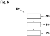
- FIG. 6 shows a flow diagram of a method 600 for manufacturing a relay valve according to an exemplary embodiment. It can be the in 1 act as described relay valve.
- the method 600 comprises a step 605 of providing, a step 610 of inserting and a step 615 of introducing.
- step 605 of providing a housing, a relay piston and a guide sleeve device are provided.
- step 610 of insertion the relay plunger is inserted into the housing.
- step 615 of insertion the guide sleeve device is inserted into the housing, with the guide sleeve device being inserted into the housing in such a way that the guide section of the guide sleeve is coupled to the counter-guide section of the collar and the holding section of the guide sleeve is fixed in the housing with a form fit.
- step 615 of inserting is performed after step 610 of inserting.
- an embodiment includes an "and/or" link between a first feature and a second feature, this should be read in such a way that the embodiment according to one embodiment includes both the first feature and the second feature and according to a further embodiment either only that having the first feature or only the second feature.
Landscapes
- Engineering & Computer Science (AREA)
- Mechanical Engineering (AREA)
- General Engineering & Computer Science (AREA)
- Transportation (AREA)
- Valves And Accessory Devices For Braking Systems (AREA)
- Valve Housings (AREA)
Description
- Der vorliegende Ansatz bezieht sich auf eine Führungshülse zum Führen einer Manschette eines Relaisventils für einen elektropneumatischen Modulator für eine Bremsanlage für ein Fahrzeug, eine Führungshülsenvorrichtung mit einer Führungshülse, ein Relaisventil mit einer Führungshülsenvorrichtung und ein Verfahren zum Herstellen eines Relaisventils.
- Es gibt Relaisventile, bei denen eine Manschette des Relaisventils auf zwei Hohlzylindern geführt wird, die durch ein Kunststoffteil wie eine Führungshülse gebildet sind. Eine Montage eines Dichtelementes und der Manschette und eine Ausrichtung geschehen durch ein Montagewerkzeug von einer oberen Seite eines Moduls eines zweiteiligen Gehäuses. Eine Befestigung der Führungshülse in dem Gehäuse wird über einen Sicherungsring im Gehäuse realisiert. Die
WO 2015/058828 A1 beschreibt ein Relaisventil für eine Druckluftanlage, eine Ventileinrichtung mit dem Relaisventil sowie ein Fahrzeug mit dem Relaisventil und/oder mit der Ventileinrichtung. DieEP 2 266 854 A2 beschreibt ein Relaisventil, einen Geräuschdämpfer, ein Ventileinrichtung und ein Fahrzeug. DieES 1 033 579 U DE 29 18 032 A1 beschreibt ein Relaisventil für druckmittelbeaufschlagte Bremsanlagen an Kraftfahrzeugen und Anhängerfahrzeugen. DieEP 2 407 355 A1 beschreibt ein Relaisventil und ein Verfahren zum Betreiben eines Relaisventils. - Vor diesem Hintergrund ist es die Aufgabe des vorliegenden Ansatzes eine verbesserte Führungshülse zum Führen einer Manschette eines Relaisventils für einen elektropneumatischen Modulator für eine Bremsanlage für ein Fahrzeug, eine Führungshülsenvorrichtung mit einer verbesserten Führungshülse, ein Relaisventil mit einer verbesserten Führungshülsenvorrichtung und ein Verfahren zum Herstellen eines verbesserten Relaisventils zu schaffen.
- Diese Aufgabe wird durch eine Führungshülse zum Führen einer Manschette eines Relaisventils für einen elektropneumatischen Modulator für eine Bremsanlage für ein Fahrzeug, eine Führungshülsenvorrichtung mit einer Führungshülse, ein Relaisventil mit einer Führungshülsenvorrichtung und ein Verfahren zum Herstellen eines Relaisventils gemäß den Hauptansprüchen gelöst.
- Die mit dem vorgestellten Ansatz erreichbaren Vorteile bestehen darin, dass eine Führungshülse für ein Relaisventil geschaffen wird, die sowohl dazu ausgeformt ist, um eine durch einen Relaiskolben bewegliche Manschette zu führen als auch, um sicher und einfach in einem Gehäuse des Relaisventils befestigt zu werden. Eine hier vorgestellte Führungshülse ist zudem vorteilhafterweise zur Verwendung mit und zur Montage in einem einteiligen Gehäuse des Relaisventils ausgeformt.
- Eine Führungshülse zum Führen einer Manschette eines Relaisventils für einen elektropneumatischen Modulator für eine Bremsanlage für ein Fahrzeug umfasst einen Führungsabschnitt und einen Halteabschnitt. Der Führungsabschnitt ist an oder in einen Gegenführungsabschnitt der Manschette des Relaisventils koppelbar ausgeformt, um ein Führen der Manschette entlang des Führungsabschnitts zu ermöglichen. Der Halteabschnitt ist dazu ausgeformt, um die Führungshülse formschlüssig in einem Gehäuse des Relaisventils zu befestigen.
- Die Manschette kann in einem betriebsbereiten Zustand des Relaisventils dazu ausgeformt und angeordnet sein, um eine Öffnung des Relaisventils zu verschließen. Durch ein Bewegen eines Relaiskolbens des Relaisventils gegen die Manschette kann die Manschette entlang des Führungsabschnitts der Führungshülse bewegt werden, um das Relaisventil zu öffnen. Die Manschette kann hierzu im betriebsbereiten Zustand des Relaisventils zwischen dem Relaiskolben und der Führungshülse angeordnet sein. Zwischen der Manschette und der Führungshülse kann eine Manschettenfeder eingespannt sein, die dazu ausgebildet ist, um ein Verschließen des Relaisventils zu bewirken, wenn der Relaiskolben beabstandet zu der Manschette angeordnet ist. Die Führungshülse selbst kann außerdem als ein Verschluss des Relaisventils dienen. Der Halteabschnitt kann beispielsweise dazu ausgeformt sein, um die Führungshülse formschlüssig in einem Hinterschnitt des Gehäuses des Relaisventils zu befestigen. Ein Außendurchmesser des Halteabschnitts kann hierzu größer sein, als ein Außendurchmesser des Führungsabschnitts, beispielsweise mehr als doppelt so groß. Eine hier vorgestellte Führungshülse ermöglicht vorteilhafterweise eine Doppelfunktion einer Führungshülse, wobei einerseits die Manchette entlang der Führungshülse zentriert geführt werden kann und andererseits eine Befestigung der Führungshülse in dem Gehäuse ermöglicht ist.
- Erfindungsgemäß formt der Halteabschnitt zumindest einen Rasthaken und zusätzlich oder alternativ ein Bajonett aus.
- Ein solcher Rasthaken und zusätzlich oder alternativ ein Bajonett wird in das Gehäuse, beispielsweise in den Hinterschnitt des Gehäuses, einrasten oder einschnappen, um eine sichere Verbindung zu ermöglichen. Hierbei kann der Rasthaken und zusätzlich oder alternativ das Bajonett dazu ausgeformt sein, um ein Herausgleiten der Führungshülse entgegen einer Einführrichtung der Führungshülse in das Gehäuse bei einer Montage der Führungshülse zu verhindern. So kann eine stabile Befestigung in einem rohrförmigen Gehäuse ermöglicht werden. Der Rasthaken ermöglicht hierbei eine beständige oder unlösbare Verbindung, während das Bajonett eine lösbare Verbindung ermöglichen kann.
- Gemäß einer Ausführungsform erstrecken sich der Führungsabschnitt und der Halteabschnitt zu zwei gegenüberliegenden Seiten der Führungshülse. Hierbei können der Führungsabschnitt und der Halteabschnitt an zwei gegenüberliegenden Enden der Führungshülse angeformt sein. So können zu einer Seite der Führungshülse die Manschette und der Relaiskolben geführt werden und zu der gegenüberliegenden Seite das Relaisventil durch den Halteabschnitt verschlossen werden.
- Hierbei ist es von Vorteil, wenn die Führungshülse gemäß einer Ausführungsform einen zwischen dem Führungsabschnitt und dem Halteabschnitt angeordneten Mittelabschnitt ausformt, der im Wesentlichen kreisringförmig oder hohlkegelstumpfförmig ausgeformt sein kann. Dieser Mittelabschnitt kann dazu dienen, um den Führungsabschnitt mit dem Halteabschnitt zu verbinden. Der Mittelabschnitt kann sich hierbei im Wesentlichen senkrecht zu einer Erstreckungsachse des Führungsabschnitts erstrecken oder sich schräg von dem Führungsabschnitt weg erstrecken. In einem rohrförmigen Gehäuse kann das Gehäuse oder das Relaisventil somit durch den Mittelabschnitt verschlossen werden. Wenn der Mittelabschnitt die Form eines Hohlkegelstumpfes oder eines Trichters ausformt, kann dies einen Raum in dem Kegelstumpf oder Trichter schaffen. Dieser Raum kann zwischen der Führungshülse und einem gegenüberliegend zu der Manschette angeordneten oder anordenbaren Schalldämpfer ausgeformt sein, damit sich Luft vor einem Ausströmen durch den Schalldämpfer in dem Raum entspannen kann.
- Beispielsweise kann der Halteabschnitt an einer Unterseite des Mittelabschnitts und zusätzlich oder alternativ der Führungsabschnitt an einer der Unterseite gegenüberliegenden Oberseite des Mittelabschnitts angeformt sein. Der Halteabschnitt kann sich hierbei von einem Randabschnitt der Unterseite des Mittelabschnitts und zusätzlich oder alternativ kann sich der Führungsabschnitt von einem im Wesentlichen mittigen Bereich der Oberseite des Mittelabschnitts weg erstrecken. Somit sind eine Befestigung der Führungshülse an einer Innenwand des Gehäuses und ein zentriertes Führen der Manschette ermöglicht.
- Es ist weiterhin von Vorteil, wenn die Führungshülse gemäß einer Ausführungsform zumindest eine Axialrippe aufweist, die sich von einer dem Halteabschnitt zugewandten Unterseite des Mittelabschnitts weg erstreckt und zusätzlich oder alternativ eine Erstreckungsachse aufweist, die parallel zu dem Führungsabschnitt verlaufend angeordnet ist. Diese Axialrippe kann stabförmig ausgeformt sein. Eine solche Axialrippe kann dazu ausgeformt sein, um im betriebsbereiten Zustand des Relaisventils mit einem Schalldämpfer, in den Schalldämpfer zu ragen oder in diesen einzupressen, um eine Stabilität der Führungshülse zu erhöhen und zusätzlich oder alternativ ein Strömen von Luft in dem Raum zu dem Gehäuse zu reduzieren. Die Führungshülse kann auch eine Mehrzahl solcher Axialrippen aufweisen, welche ringförmig angeordnet sein können.
- Zusätzlich oder alternativ kann die Führungshülse zumindest eine Radialrippe aufweisen, die sich an einer dem Halteabschnitt zugewandten Unterseite des Mittelabschnitts radial zwischen einer Hülsendurchgangsöffnung der Führungshülse und dem Halteabschnitt erstrecken kann. Eine solche Radialrippe kann vorteilhafterweise entstehende Luftwirbel in dem Raum reduzieren. Die Führungshülse kann auch eine Mehrzahl solcher Radialrippen aufweisen, welche radial um die Hülsendurchgangsöffnung verlaufend angeordnet sein können.
- Der Führungsabschnitt kann eine Außenhülse und eine von der Außenhülse umschlossene Innenhülse ausformen, wobei die Innenhülse eine Hülsendurchgangsöffnung der Führungshülse umfassen kann. Somit können die Außenhülse und zusätzlich oder alternativ die Innenhülse beim Koppeln mit der Manschette in den Gegenführungsabschnitt der Manschette gesteckt oder eingeführt werden. Der Gegenführungsabschnitt kann ähnlich ausgeformt sein, wie der Führungsabschnitt.
- Gemäß einer vorteilhaften Ausführungsform ist die Führungshülse einstückig und zusätzlich oder alternativ insgesamt trichterförmig ausgeformt. Eine solche einstückige Führungshülse ist einfach durch beispielsweise einen Spritzguss herstellbar und erfordert dabei wenig Material und Kosten in der Herstellung.
- Eine Führungshülsenvorrichtung weist eine Führungshülse in einer der voranstehend vorgestellten Varianten und die Manschette auf, wobei ein Innendurchmesser der Manschette gleich oder kleiner ist als ein Innendurchmesser des Führungsabschnitts der Führungshülse. Eine solche Führungshülsenvorrichtung kann aufgrund der aufeinander angepassten Innendurchmesser des Führungsabschnitts und der Manschette bei einer Montage vorteilhafterweise mit einem einzigen Montagewerkzeug und einem einzigen Montageschritt gemeinsam von einer Seite in das Gehäuse montiert werden. Dies ist insbesondere von Vorteil, wenn auch das Gehäuse des Relaisventils einstückig ausgeformt ist und die in einer Aufnahmekammer des Gehäuses anordenbaren Relaisventilkomponenten bei einer Montage des Relaisventils nacheinander von einer Seite in die Aufnahmekammer eingestapelt werden. Der Gegenführungsabschnitt der Manschette und der Führungsabschnitt können dazu ausgeformt sein, um einen Spalt zwischen dem Gegenführungsabschnitt und dem Führungsabschnitt abzudichten. Hierbei kann ein Ende des Gegenführungsabschnitts ein Dichtelement ausformen, das in dem gekoppelten Zustand des Führungsabschnitts an oder in dem Gegenführungsabschnitt an dem Führungsabschnitt anliegen kann und zusätzlich oder alternativ kann in dem gekoppelten Zustand des Führungsabschnitts an oder in dem Gegenführungsabschnitt ein enger Kontakt herrschen.
- Ein Relaisventil weist ein Gehäuse, eine in dem Gehäuse anordenbare oder angeordnete Führungshülsenvorrichtung, die in einer der vorangehend vorgestellten Varianten ausgeformt ist, und einen in dem Gehäuse anordenbaren oder angeordneten Relaiskolben zum Bewegen der Manschette entlang des Führungsabschnitts der Führungshülse auf. Das Gehäuse kann einstückig ausgeformt sein. Der Relaiskolben und die Führungshülsenvorrichtung können in eine Aufnahmekammer des Relaiskolbens ausgenommen sein oder aufgenommen werden. Ein solches Relaisventil weist vorteilhafterweise sehr wenige Bauteile auf und ist einfach montierbar.
- Ein Verfahren zum Herstellen eines Relaisventils umfasst einen Schritt des Bereitstellens, einen Schritt des Einfügens und einen Schritt des Einführens. Im Schritt des Bereitstellens werden ein Gehäuse, ein Relaiskolben und eine Führungshülsenvorrichtung bereitgestellt, die in einer der vorangehend vorgestellten Varianten ausgeformt ist. Im Schritt des Einfügens wird der Relaiskolben in das Gehäuse eingefügt. Im Schritt des Einführens wird die Führungshülsenvorrichtung in das Gehäuse eingeführt, wobei die Führungshülsenvorrichtung derart in das Gehäuse eingeführt wird, dass der Führungsabschnitt der Führungshülse an den Gegenführungsabschnitt der Manschette gekoppelt ist und der Halteabschnitt der Führungshülse formschlüssig in dem Gehäuse befestigt ist, indem der Halteabschnitt in einen Hinterschnitt des Gehäuses einrastet oder einschnappt.
- Ausführungsbeispiele des hier vorgestellten Ansatzes werden in der nachfolgenden Beschreibung mit Bezug zu den Figuren näher erläutert. Es zeigen:
-
Fig. 1 eine schematische seitliche Querschnittsdarstellung eines elektropneumatischen Modulators mit einem Relaisventil mit einer Führungshülse zum Führen einer Manschette des Relaisventils gemäß einem Ausführungsbeispiel; -
Fig. 2 einen Ausschnitt einer seitlichen Querschnittsdarstellung einer Führungshülsenvorrichtung gemäß einem Ausführungsbeispiel; -
Fig. 3 eine schematische Querschnittsdarstellung einer Unterseite einer Führungshülse gemäß einem Ausführungsbeispiel; -
Fig. 4 einen Ausschnitt einer seitlichen Querschnittsdarstellung einer Führungshülsenvorrichtung gemäß einem Ausführungsbeispiel; und -
Fig. 5 eine schematische Querschnittsdarstellung eines Fahrzeugs 500 mit einem elektropneumatischen Modulator 100 mit einer Führungshülsenvorrichtung gemäß einem Ausführungsbeispiel; und -
Fig. 6 ein Ablaufdiagramm eines Verfahrens zum Herstellen eines Relaisventils gemäß einem Ausführungsbeispiel. - In der nachfolgenden Beschreibung günstiger Ausführungsbeispiele des vorliegenden Ansatzes werden für die in den verschiedenen Figuren dargestellten und ähnlich wirkenden Elemente gleiche oder ähnliche Bezugszeichen verwendet, wobei auf eine wiederholte Beschreibung dieser Elemente verzichtet wird.
-
Fig. 1 zeigt eine schematische seitliche Querschnittsdarstellung eines elektropneumatischen Modulators 100 mit einem Relaisventil 105 mit einer Führungshülse 110 zum Führen einer Manschette 115 des Relaisventils 105 gemäß einem Ausführungsbeispiel. - Der elektropneumatische Modulator 100 ist zur Verwendung für eine elektropneumatische Bremsanlage für ein Fahrzeug ausgeformt und in einem hier dargestellten betriebsbereiten Zustand dazu ausgebildet, um bei einem Bremsvorgang des Fahrzeugs einen bereitgestellten pneumatischen Bremsdruck, also Druckluft, zu regeln.
- Lediglich beispielhaft ist das Relaisventil 105 gemäß diesem Ausführungsbeispiel Teil des elektropneumatischen Modulators 100. Das Relaisventil 105 umfasst ein Gehäuse 120, eine in dem Gehäuse 120 anordenbare oder angeordnete Führungshülsenvorrichtung 125 und einen in dem Gehäuse 120 anordenbaren oder angeordneten Relaiskolben 130. Die Führungshülsenvorrichtung 125 umfasst die Führungshülse 110 und die Manschette 115. Gemäß diesem Ausführungsbeispiel ist das Relaisventil 105 in einem betriebsbereiten Zustand angeordnet, in dem der Relaiskolben 130 und die Führungshülsenvorrichtung 125 in dem Gehäuse 120 aufgenommen sind. Die Manschette 115 ist gemäß diesem Ausführungsbeispiel zwischen dem Relaiskolben 130 und der Führungshülse 110 angeordnet.
- Es folgt eine Beschreibung einer beispielhaften Funktion des elektropneumatischen Modulators 100:
Gemäß einem Ausführungsbeispiel ist der elektropneumatische Modulator 100 Teil der Bremsanlage des Fahrzeugs. Die Bremsanlage umfasst gemäß einem Ausführungsbeispiel neben dem Modulator 100 einen Vorratsbehälter zum Bereitstellen von Druckluft, eine Steuereinrichtung zum Bereitstellen eines elektrischen Steuersignals, eine Fußbremseinrichtung zum Bereitstellen eines pneumatischen Steuersignals und/oder eine Radbremseinrichtung zum Abbremsen eines Rads des Fahrzeugs. Die Funktionalität des Modulators 100 entspricht gemäß einem Ausführungsbeispiel der Funktionalität bekannter im Zusammenhang mit Bremsanlagen eingesetzten elektropneumatischen Modulatoren. Der elektropneumatische Modulator 100 weist gemäß diesem Ausführungsbeispiel einen elektrischen Steuereingang zum Empfangen des elektrischen Steuersignals von der Steuereinrichtung, einen Vorratsanschluss 135 zum Zuführen der Druckluft von dem Vorratsbehälter, einen pneumatischen Steuereingang 140 zum Zuführen der Druckluft von dem Vorratsbehälter ansprechend auf das pneumatische Steuersignal und einen Bremsausgang 145 zum Ausgeben eines Bremsdrucks an die Radbremseinrichtung auf. Die Radbremseinrichtung kann entsprechend einer im Fahrzeugbereich üblichen Bremse ausgeführt sein, und beispielsweise einen durch den Bremsdruck betätigbaren Bremszylinder umfassen. Das elektrische Steuersignal stellt gemäß einem Ausführungsbeispiel ein elektrisches Signal dar. Beispielsweise kann das elektrische Steuersignal einen angeforderten Sollbremsdruck anzeigen. In diesem Fall ist die Steuereinrichtung beispielsweise als ein Bremssteuergerät ausgeführt und der elektropneumatische Modulator 100 umfasst beispielsweise zumindest ein Magnetventil, das unter Verwendung des elektrischen Steuersignals oder eines ansprechend auf einen Empfang des elektrischen Steuersignals generiertes Signal betätigbar ist. Gemäß diesem Ausführungsbeispiel sind der Relaiskolben 130 und die Führungshülsenvorrichtung 125 übereinander in einer Aufnahmekammer 150 des Gehäuses 120 aufgenommen. Der Bremsausgang 145 und der Vorratsanschluss 135 münden in die Aufnahmekammer 150. Das Relaisventil 105 ist dazu ausgebildet und ausgeformt, um eine fluidische Verbindung zwischen dem Vorratsanschluss 135 und dem Bremsausgang 145 durch eine Bewegung des Relaiskolbens 130 zu öffnen oder zu verschließen. Die Aufnahmekammer 150 umfasst einen Steuerkammerabschnitt, der gesteuert durch das elektrische Steuersignal mit zugeführter Druckluft beaufschlagt werden kann, um eine Schaltbewegung des Relaiskolbens 130 zu bewirken. Die Aufnahmekammer 150 umfasst gemäß einem Ausführungsbeispiel außerdem einen Arbeitskammerabschnitt, der fluidisch mit dem Bremsausgang 145 verbunden ist, und durch die Schaltbewegung des Relaiskolbens 130 mit über den Vorratsanschluss 135 zugeführter Druckluft beaufschlagt werden kann, um den Bremsdruck an dem Bremsausgang 145 bereitzustellen. - Die hier vorgestellte Führungshülse 110 ist gemäß diesem Ausführungsbeispiel in oder an dem Relaisventil 105 aufgenommen. Die Führungshülse 110 ist dazu ausgeformt, um die Manschette 115 des Relaisventils 105 zu führen und/oder in dem Gehäuse 120 zu befestigen. Hierzu umfasst die Führungshülse 110 einen Führungsabschnitt 155 und einen Halteabschnitt 160. Der Führungsabschnitt 155 ist an oder in einen Gegenführungsabschnitt der Manschette 115 des Relaisventils 105 koppelbar ausgeformt, um ein Führen der Manschette 115 entlang des Führungsabschnitts 110 zu ermöglichen. Zwischen der Manschette und dem Führungsabschnitt 110 ist gemäß diesem Ausführungsbeispiel eine Manschettenfeder eingespannt.
- Der Halteabschnitt 160 ist dazu ausgeformt, um die Führungshülse 110 formschlüssig in dem Gehäuse 120 des Relaisventils 105 zu befestigen.
- Gemäß diesem Ausführungsbeispiel ist das Relaisventil 105 in einem betriebsbereiten Zustand angeordnet, in dem der Führungsabschnitt 155 der Führungshülse 110 an oder in den Gegenführungsabschnitt der Manschette 115 gekoppelt angeordnet ist und der Halteabschnitt 160 der Führungshülse 110 formschlüssig in dem Gehäuse 120 befestigt ist. Gemäß diesem Ausführungsbeispiel ist das Relaisventil 105 in einem geschlossenen Zustand angeordnet, in dem der Vorratsanschluss 135 und der Bremsausgang 145 fluidisch nicht miteinander verbunden sind. Der Relaiskolben 130 ist hierbei beabstandet zu der Manschette 115 angeordnet und bewegt diese somit nicht entlang des Führungsabschnitts 155. Der Relaiskolben 130 des Relaisventils 105 ist dazu ausgeformt, um die Manschette 115 entlang des Führungsabschnitts 155 der Führungshülse 110 zu bewegen, um ein Öffnen des Relaisventils 105 zu bewirken. Gemäß diesem Ausführungsbeispiel ist auf einer dem Halteabschnitt 160 zugewandten Seite der Führungshülse 110 ein Schalldämpfer 165 angeordnet. Gemäß einem Ausführungsbeispiel ist der Schalldämpfer 165 Teil des Relaisventils 105 und/oder zumindest teilweise in dem Gehäuse 120 angeordnet.
-
Fig. 2 zeigt einen Ausschnitt einer seitlichen Querschnittsdarstellung einer Führungshülsenvorrichtung 125 gemäß einem Ausführungsbeispiel. Dabei kann es sich um die inFig. 1 beschriebene Führungshülsenvorrichtung 125 handeln, bei der die Führungshülse 110 und die Manschette 115 miteinander gekoppelt sind. Auch bei dem Gehäuse 120 kann es sich um das inFig. 1 beschriebene Gehäuse 120 und bei dem Schalldämpfer 165 kann es sich um den inFig. 1 beschriebenen Schalldämpfer 165 handeln. Dargestellt ist inFig. 2 lediglich eine von zwei Hälften des Querschnitts. Eine nicht dargestellte andere Hälfte kann entsprechend der hier gezeigten Hälfte ausgeformt sein. - Erfindungsgemäß formt der Halteabschnitt 160 zumindest einen Rasthaken oder gemäß einem alternativen Ausführungsbeispiel ein Bajonett aus. Dieser Rasthaken ist gemäß einem Ausführungsbeispiel in einem Hinterschnitt des Gehäuses 120 eingerastet. Der Rasthaken, der auch als eine seitliche Schnapprippe bezeichnet werden kann, bewirkt gemäß diesem Ausführungsbeispiel eine radiale Verpressung des Schalldämpfers 165 oder anders ausgedrückt eine radiale Außenpressung 200 auf den Schalldämpfer 165.
- Der Führungsabschnitt 155 und der Halteabschnitt 160 erstrecken sich gemäß diesem Ausführungsbeispiel zu zwei gegenüberliegenden Seiten der Führungshülse 110. Eine Erstreckungsachse des Führungsabschnitts 155 verläuft dabei parallel zu einer vorgesehenen Bewegungsachse des Relaiskolbens und/oder einer Erstreckungsachse einer Innenwand des Gehäuses 120. Eine Erstreckungsachse des Halteabschnitts 160 in Form des Rasthakens ist schräg zu der Erstreckungsachse des Führungsabschnitts 155 verlaufend angeordnet. Zwischen dem Führungsabschnitt 155 und dem Halteabschnitt 160 formt die Führungshülse 110 gemäß diesem Ausführungsbeispiel einen Mittelabschnitt 205 aus, der im Wesentlichen kreisringförmig oder hohlkegelstumpfförmig ausgeformt ist. Gemäß diesem Ausführungsbeispiel ist der Mittelabschnitt 205 kreisringförmig ausgeformt, in
Fig. 1 ist eine hohlkegelstumpfförmige Ausgestaltung des Mittelabschnitts 205 dargestellt. Der Halteabschnitt 160 erstreckt sich gemäß diesem Ausführungsbeispiel von einer Unterseite des Mittelabschnitts 205 und der Führungsabschnitt 155 von einer der Unterseite gegenüberliegend angeordneten Oberseite des Mittelabschnitts 205. Der Halteabschnitt 160 erstreckt sich gemäß diesem Ausführungsbeispiel von einem äußeren Randabschnitt der Unterseite und/oder der Führungsabschnitt 155 von einem im Wesentlichen mittigen Bereich der Oberseite weg. Zwischen der Oberseite und dem Randabschnitt weist der Mittelabschnitt 205 gemäß diesem Ausführungsbeispiel eine Stufe 210 auf, in welcher ein Dichtelement 215 aufgenommen ist, das dazu ausgeformt ist, um die Führungshülse 110 gegen das Gehäuse 120 abzudichten. Bei dem Dichtelement 215 handelt es sich gemäß diesem Ausführungsbeispiel um einen Dichtring, der in einer umlaufend verlaufenden Stufe 210 angeordnet ist. - Die Führungshülse 110 weist gemäß diesem Ausführungsbeispiel zumindest eine Axialrippe 220 auf, die sich von der dem Halteabschnitt 160 zugewandten Unterseite des Mittelabschnitts 205 weg erstreckt. Eine Erstreckungsachse der Axialrippe 220 ist gemäß diesem Ausführungsbeispiel parallel zu dem Führungsabschnitt 155 verlaufend angeordnet. Eine Erstreckungslänge der Axialrippe 220 ist gemäß diesem Ausführungsbeispiel länger als eine Erstreckungslänge des Rasthakens. Die Axialrippe 220 erstreckt sich gemäß diesem Ausführungsbeispiel von einem mittigen Bereich eines Radius des Mittelabschnitts 205 weg und/oder ermöglicht eine axiale Pressung in den Schalldämpfer 165.
- Die Führungshülse 110 weist gemäß diesem Ausführungsbeispiel zumindest eine Radialrippe 225 auf, die sich an der Unterseite des Mittelabschnitts 205 radial zwischen einer Hülsendurchgangsöffnung 230 der Führungshülse 110 und dem Halteabschnitt 160 erstreckt. Gemäß diesem Ausführungsbeispiel verläuft die Radialrippe 225 von der Hülsendurchgangsöffnung 230 schräg oder keilförmig zu dem Halteabschnitt 160 hin.
- Gemäß einem Ausführungsbeispiel ist die Axialrippe 220 an der Radialrippe 225 angeordnet.
- Der Führungsabschnitt 155 formt gemäß diesem Ausführungsbeispiel eine Außenhülse und eine von der Außenhülse umschlossene Innenhülse aus, wobei die Innenhülse die Hülsendurchgangsöffnung 230 der Führungshülse 110 umfasst. Ein Innendurchmesser der Manschette 115 ist gemäß diesem Ausführungsbeispiel gleich oder gemäß einem alternativen Ausführungsbeispiel kleiner als ein Innendurchmesser des Führungsabschnitts 155 der Führungshülse 110. Der Gegenführungsabschnitt 235 der Manschette 115 und der Führungsabschnitt 155 sind gemäß diesem Ausführungsbeispiel ausgeformt, um einen Spalt zwischen dem Gegenführungsabschnitt 235 und dem Führungsabschnitt 155 abzudichten. Gemäß diesem Ausführungsbeispiel liegt der Gegenführungsabschnitt 235 an oder in jeweils einer Außenwand der Innenhülse und der Außenhülse an.
- Die Führungshülse 110 ist gemäß diesem Ausführungsbeispiel einstückig und/oder insgesamt trichterförmig ausgeformt.
- Im Folgenden werden Ausführungsbeispiele der Führungshülsenvorrichtung 125 oder der Führungshülse 110 noch einmal genauer mit anderen Worten beschrieben:
Die hier vorgestellte Führungshülse 110 kann auch als eine Führungshülse 110 mit Schnappgeometrie bezeichnet werden. Eine Aufgabe der Führungshülse 110 ist es, die Führung der Manschette 115 zu bilden. Gemäß diesem Ausführungsbeispiel realisiert die Führungshülsenvorrichtung 125 aufeinander angepasste Manschetten- und Führungshülseninnendurchmesser. Eine Montage der Führungshülsenvorrichtung 125 ist nun vorteilhafterweise von unten in das Gehäuse 120 möglich, da durch ein Montagewerkzeug die Manschette 115 auf der Führungshülse 110 ausgerichtet werden kann, siehe hierzu auch das Montagewerkzeug inFig. 4 . Eine solche Montage von unten ist eine Grundvoraussetzung für ein in einem oberen Bereich geschlossenes Gehäuse 120, gemäß diesem Ausführungsbeispiel ein einteiliges Gehäuse 120, das zur Kostenersparnis beiträgt. - Eine weitere Aufgabe der Führungshülse 110 ist es, pneumatische Kräfte abzufangen und einen geschlossenen Druckbereich zu bilden. Durch die Verrastung der Schnappgeometrie der Führungshülse 110 in dem Gehäuse 120 ist vorteilhafterweise eine Ersparnis eines zusätzlichen Sicherungsringes ermöglicht und zusätzlich entsteht vorteilhafterweise ein sehr geringer Montageaufwand. Gemäß einem Ausführungsbeispiel ist der Rasthaken unlösbar in dem Gehäuse 120 eingerastet. Ein Vorteil liegt zudem darin, dass keine unzulässigen Ersatzteile eingebaut werden können, da eine zerstörungsfreie Entfernung der Führungshülse 110 nicht möglich ist.
- Eine weitere Aufgabe der Führungshülse 110 ist es, bei einer Entlüftung Luft zum Schalldämpfer 165 zu führen. Diese Aufgabe wird durch die Führungshülse 165 gelöst, indem oberhalb des Gewebes des Schalldämpfers 165 ein Raum 240 geschaffen ist, in dem sich die Luft vor einem Ausströmen aus dem Schalldämpfer 165 entspannen kann. Die seitlichen Rippen in Form der Radialrippen 225 in diesem Raum 240 sorgen dafür, dass entstehende Luftwirbel reduziert werden. Der Halteabschnitt 160 in Form von seitlichen Schnapprippen bewirkt die radiale Verpressung 200 des Gestrickes und somit wird ein Vorbeiströmen der Luft zwischen dem Gehäuse 120 und dem Schalldämpder 165 effektiv verhindert. Zusätzlich wirkt noch eine axiale Verpressrippe in Form der Axialrippe 220, welche einen Luftstrom 245 in Richtung Gehäuse 120 reduziert.
- Eine Montage der Führungshülsenvorrichtung 125 und/oder eine Ausrichtung ist vorteilhafterweise durch ein einziges Montagewerkzeug von einer unteren Seite des Gehäuses 120 ermöglicht. Das Relaisventil oder sogar der gesamte elektropneumatische Modulator kann somit vorteilhafterweise in ein einteiliges Gehäuse 120 montiert angeordnet sein oder montiert werden, siehe auch
Fig. 1 . Zusätzliche Bauteile wie ein Sicherungsring zur Befestigung der Führungshülse 110 oder des gesamten Relaisventils in dem Gehäuse 120 sind vorteilhafterweise dank des Halteabschnitts 160 nicht nötig. Aufgrund der schrägen Ausformung des Halteabschnitts 160 ist gemäß diesem Ausführungsbeispiel zwischen der Unterseite des Mittelabschnitts 205 und dem Schalldämpfer 165 der Raum 240 geschaffen, der eine Dämpfung eines durch die Hülsendurchgangsöffnung 230 zu dem Schalldämpfer 165 strömenden Luftstroms 245 ermöglicht. Eine zusätzliche Dämpfungsplatte mit Löchern zwischen der Führungshülse 110 und dem Schalldämpfer 165 ist somit nicht nötig. Gemäß einem alternativen Ausführungsbeispiel ist zwischen der Führungshülse 110 und dem Schalldämpfer 165 dennoch eine solche Dämpfungsplatte mit Löchern angeordnet, um eine noch stärkere Dämpfung des Luftstroms 245 zu bewirken. Aufgrund der verpressenden Wirkung des Halteabschnitts 160 an dem Schalldämpfer 165 ist zudem keine zusätzliche Kreis-Verpressung im Gewebe des Schalldämpfers 165 zwischen dem Gehäuse 120 und dem Schalldämpfer 165 vonnöten, um ein seitliches Umströmen des Gewebes zu verhindern. Auch diese Aufgabe ist durch den Halteabschnitt 160 gelöst. Gemäß einem alternativen Ausführungsbeispiel ist eine zusätzliche Verpressung des Gewebes des Schalldämpfers 165 durch eine weitere Stufe im Gehäuse 120 realisiert. - Gemäß einem alternativen Ausführungsbeispiel ist auch ein Innendurchmesser der Führungshülse 110 mit Rippen und/oder Stegen verstärkt, wobei zur Montage ein geschlitztes Montagewerkzeug einsetzbar ist. Eine Manschette, welche gemäß einem alternativen Ausführungsbeispiel im Innendurchmesser kleiner ist, als die Führungshülse 110, ist mit einem stufenförmigen Montagewerkzeug zentrierbar. Gemäß einem alternativen Ausführungsbeispiel ist der Raum 240 zumindest teilweise durch das Gehäuse 120 in Form eines Gussgehäuses selber gebildet.
-
Fig. 3 zeigt eine schematische Querschnittsdarstellung einer Unterseite einer Führungshülse 110 gemäß einem Ausführungsbeispiel. Dabei kann es sich um ein Ausführungsbeispiel der inFig. 1 oderFig. 2 beschriebenen Führungshülse 110 handeln. - Gemäß diesem Ausführungsbeispiel weist die Unterseite der Führungshülse 110 eine Mehrzahl von Radialrippen 225 auf, die radial um die Hülsendurchgangsöffnung 230 angeordnet sind. Gemäß diesem Ausführungsbeispiel weist die Unterseite acht der Radialrippen 225 auf, die gleichmäßig zueinander beabstandet angeordnet sind.
- Der Halteabschnitt 160 ist gemäß diesem Ausführungsbeispiel umlaufend an einem Umlaufrand des Mittelabschnitts angeordnet oder eine Mehrzahl von den Halteabschnitt 160 ausformenden Rasthaken ist umlaufend an umlaufenden Randabschnitten des Umlaufrands angeordnet. Gemäß einem Ausführungsbeispiel formen zwanzig derartige Rasthaken den Halteabschnitt 160 aus. Gemäß einem Ausführungsbeispiel sind an der Unterseite auch eine Mehrzahl der Axialrippen angeordnet, gemäß einem Ausführungsbeispiel acht der Axialrippen, die gemäß einem Ausführungsbeispiel gleichmäßig zueinander beabstandet und/oder ringförmig angeordnet sind und somit gemäß einem Ausführungsbeispiel eine axiale Kreispressung in den Schalldämpfer ermöglichen.
-
Fig. 4 zeigt einen Ausschnitt einer seitlichen Querschnittsdarstellung einer Führungshülsenvorrichtung 125 gemäß einem Ausführungsbeispiel. Dabei kann es sich um den inFig. 2 beschriebenen Abschnitt handeln, wobei die Führungshülsenvorrichtung 125 gemäß diesem Ausführungsbeispiel während einer Montage an das Gehäuse 120 mit einem Montagewerkzeug 400 dargestellt ist. Zwei Führungsflächen 405 und/oder eine Ausrichtung sind gemäß diesem Ausführungsbeispiel auf einer Achse angeordnet. -
Fig. 5 zeigt eine schematische Querschnittsdarstellung eines Fahrzeugs 500 mit einem elektropneumatischen Modulator 100 mit einer Führungshülsenvorrichtung 125 und einem Relaiskolben 130 gemäß einem Ausführungsbeispiel. Dabei kann es sich um den inFig. 1 beschriebenen Modulator 100 mit der in einer der vorangehenden Figuren vorgestellten Führungshülsenvorrichtung 125 handeln. - Der Modulator 100 ist gemäß diesem Ausführungsbeispiel in oder an eine elektropneumatische Bremsanlage 505 gekoppelt angeordnet. Die Bremsanlage 505 umfasst gemäß einem Ausführungsbeispiel neben dem Modulator 100 einen Vorratsbehälter 510 zum Bereitstellen von Druckluft, eine Steuereinrichtung 512 zum Bereitstellen eines elektrischen Steuersignals, eine Fußbremseinrichtung 515 zum Bereitstellen des pneumatischen Steuersignals und/oder eine Radbremseinrichtung 520 zum Abbremsen eines Rads des Fahrzeugs 500.
-
Fig. 6 zeigt ein Ablaufdiagramm eines Verfahrens 600 zum Herstellen eines Relaisventils gemäß einem Ausführungsbeispiel. Dabei kann es sich um das inFig. 1 beschriebene Relaisventil handeln. - Das Verfahren 600 umfasst einen Schritt 605 des Bereitstellens, einen Schritt 610 des Einfügens und einen Schritt 615 des Einführens.
- Im Schritt 605 des Bereitstellens werden ein Gehäuse, ein Relaiskolben und eine Führungshülsenvorrichtung bereitgestellt. Im Schritt 610 des Einfügens wird der Relaiskolben in das Gehäuse eingefügt. Im Schritt 615 des Einführens wird die Führungshülsenvorrichtung in das Gehäuse eingeführt, wobei die Führungshülsenvorrichtung derart in das Gehäuse eingeführt wird, dass der Führungsabschnitt der Führungshülse an den Gegenführungsabschnitt der Manschette gekoppelt ist und der Halteabschnitt der Führungshülse formschlüssig in dem Gehäuse befestigt ist.
- Gemäß diesem Ausführungsbeispiel wird der Schritt 615 des Einführens nach dem Schritt 610 des Einfügens ausgeführt.
- Umfasst ein Ausführungsbeispiel eine "und/oder"-Verknüpfung zwischen einem ersten Merkmal und einem zweiten Merkmal, so ist dies so zu lesen, dass das Ausführungsbeispiel gemäß einer Ausführungsform sowohl das erste Merkmal als auch das zweite Merkmal und gemäß einer weiteren Ausführungsform entweder nur das erste Merkmal oder nur das zweite Merkmal aufweist.
-
- 100
- elektropneumatischer Modulator
- 105
- Relaisventil
- 110
- Führungshülse
- 115
- Manschette
- 120
- Gehäuse
- 125
- Führungshülsenvorrichtung
- 130
- Relaiskolben
- 135
- Vorratsanschluss
- 140
- pneumatischer Steuereingang
- 145
- Bremsausgang
- 150
- Aufnahmekammer
- 155
- Führungsabschnitt
- 160
- Halteabschnitt
- 165
- Schalldämpfer
- 200
- Außenpressung
- 205
- Mittelabschnitt
- 210
- Stufe
- 215
- Dichtelement
- 220
- Axialrippe
- 225
- Radialrippe
- 230
- Hülsendurchgangsöffnung
- 235
- Gegenführungsabschnitt
- 240
- Raum
- 245
- Luftstrom
- 400
- Montagewerkzeug
- 405
- Führungsfläche
- 500
- Fahrzeug
- 505
- Bremsanlage
- 510
- Vorratsbehälter
- 512
- Steuereinrichtung
- 515
- Fußbremseinrichtung
- 520
- Radbremseinrichtung
- 600
- Verfahren zum Herstellen eines Relaisventils
- 605
- Schritt des Bereitstellens
- 610
- Schritt des Einfügens
- 615
- Schritt des Einführens
Claims (13)
- Führungshülse (110) zum Führen einer Manschette (115) eines Relaisventils (105) für einen elektropneumatischen Modulator (100) für eine Bremsanlage (505) für ein Fahrzeug (500), wobei die Führungshülse (110) die folgenden Merkmale umfasst:einen Führungsabschnitt (155), der an einen Gegenführungsabschnitt (235) der Manschette (115) des Relaisventils (105) koppelbar ausgeformt ist, um ein Führen der Manschette (115) entlang des Führungsabschnitts (155) zu ermöglichen; undeinen Halteabschnitt (160), der dazu ausgeformt ist, um die Führungshülse (110) formschlüssig in einem Gehäuse (120) des Relaisventils (105) zu befestigen,dadurch gekennzeichnet, dassder Halteabschnitt (160) zumindest einen Rasthaken und/oder ein Bajonett ausformt, um in einen Hinterschnitt des Gehäuses (120) einzurasten oder einzuschnappen.
- Führungshülse (110) gemäß Anspruch 1, bei der sich der Führungsabschnitt (155) und der Halteabschnitt (160) zu zwei gegenüberliegenden Seiten der Führungshülse (110) erstrecken.
- Führungshülse (110) gemäß einem der vorangegangenen Ansprüche, mit einem zwischen dem Führungsabschnitt (155) und dem Halteabschnitt (160) ausgeformten Mittelabschnitt (205), der im Wesentlichen kreisringförmig oder hohlkegelstumpfförmig ausgeformt ist.
- Führungshülse (110) gemäß Anspruch 3, bei der sich der Halteabschnitt (160) von einem Randabschnitt einer Unterseite des Mittelabschnitts und/oder der Führungsabschnitt (155) von einem im Wesentlichen mittigen Bereich einer der Unterseite gegenüberliegend angeordneten Oberseite des Mittelabschnitts (205) weg erstreckt.
- Führungshülse (110) gemäß einem der Ansprüche 3 bis 4, mit zumindest einer Axialrippe (220), die sich von einer dem Halteabschnitt (160) zugewandten Unterseite des Mittelabschnitts (205) weg erstreckt und/oder eine Erstreckungsachse aufweist, die parallel zu dem Führungsabschnitt (155) verlaufend angeordnet ist.
- Führungshülse (110) gemäß einem der Ansprüche 3 bis 5, mit zumindest einer Radialrippe (225), die sich an einer dem Halteabschnitt (160) zugewandten Unterseite des Mittelabschnitts (225) radial zwischen einer Hülsendurchgangsöffnung (230) der Führungshülse (110) und dem Halteabschnitt (160) erstreckt.
- Führungshülse (110) gemäß einem der vorangegangenen Ansprüche, bei der der Führungsabschnitt (155) eine Außenhülse und eine von der Außenhülse umschlossene Innenhülse ausformt, wobei die Innenhülse eine Hülsendurchgangsöffnung (230) der Führungshülse (110) umfasst.
- Führungshülse (110) gemäß einem der vorangegangenen Ansprüche, die einstückig und/oder trichterförmig ausgeformt ist.
- Führungshülsenvorrichtung (125) mit einer Führungshülse (110) gemäß einem der vorangegangenen Ansprüche und der Manschette (115), wobei ein Innendurchmesser der Manschette (115) gleich oder kleiner ist als ein Innendurchmesser des Führungsabschnitts (155) der Führungshülse (110).
- Führungshülsenvorrichtung (125) gemäß Anspruch 10, bei der der Gegenführungsabschnitt (235) der Manschette (115) und der Führungsabschnitt (155) ausgeformt sind, um einen Spalt zwischen dem Gegenführungsabschnitt (235) und dem Führungsabschnitt (155) abzudichten.
- Relaisventil (105) mit einem Gehäuse (120) mit einem Hinterschnitt, einer in dem Gehäuse (120) angeordneten Führungshülsenvorrichtung (125) gemäß einem der Ansprüche 9 bis 10 und einem in dem Gehäuse (120) anordenbaren oder angeordneten Relaiskolben (130) zum Bewegen der Manschette (115) entlang des Führungsabschnitts (155) der Führungshülse (110).
- Relaisventil (105) gemäß Anspruch 11, bei dem das Gehäuse (120) einstückig ausgeformt ist.
- Verfahren (600) zum Herstellen eines Relaisventils (105), wobei das Verfahren (600) die folgenden Schritte umfasst:Bereitstellen (605) eines Gehäuses (120), eines Relaiskolbens (130) und einer Führungshülsenvorrichtung (125) gemäß einem der Ansprüche 9 bis 10;Einfügen (610) des Relaiskolbens (130) in das Gehäuse (120);Einführen (615) der Führungshülsenvorrichtung (125) in das Gehäuse (120), wobei die Führungshülsenvorrichtung (125) derart in das Gehäuse (120) eingeführt wird, dass der Führungsabschnitt (155) der Führungshülse (110) an den Gegenführungsabschnitt (235) der Manschette (115) gekoppelt ist und der Halteabschnitt (160) der Führungshülse (110) formschlüssig in dem Gehäuse (120) befestigt ist, indem der Halteabschnitt (160) zumindest einen Rasthaken und/oder ein Bajonett ausformt, um in einen Hinterschnitt des Gehäuses (120) einzurasten oder einzuschnappen.
Applications Claiming Priority (2)
| Application Number | Priority Date | Filing Date | Title |
|---|---|---|---|
| DE102018121718.8A DE102018121718A1 (de) | 2018-09-06 | 2018-09-06 | Führungshülse zum Führen einer Manschette eines Relaisventils für einen elektropneumatischen Modulator für eine Bremsanlage für ein Fahrzeug, Führungshülsenvorrichtung mit einer Führungshülse, Relaisventil mit einer Führungshülsenvorrichtung und Verfahren zum Herstellen eines Relaisventils |
| PCT/EP2019/070964 WO2020048706A1 (de) | 2018-09-06 | 2019-08-05 | Führungshülse zum führen einer manschette eines relaisventils für einen elektropneumatischen modulator |
Publications (2)
| Publication Number | Publication Date |
|---|---|
| EP3847063A1 EP3847063A1 (de) | 2021-07-14 |
| EP3847063B1 true EP3847063B1 (de) | 2023-06-07 |
Family
ID=67688734
Family Applications (1)
| Application Number | Title | Priority Date | Filing Date |
|---|---|---|---|
| EP19756121.0A Active EP3847063B1 (de) | 2018-09-06 | 2019-08-05 | Führungshülse zum führen einer manschette eines relaisventils für einen elektropneumatischen modulator |
Country Status (6)
| Country | Link |
|---|---|
| US (1) | US11738731B2 (de) |
| EP (1) | EP3847063B1 (de) |
| JP (1) | JP7155408B2 (de) |
| CN (1) | CN112672939B (de) |
| DE (1) | DE102018121718A1 (de) |
| WO (1) | WO2020048706A1 (de) |
Cited By (1)
| Publication number | Priority date | Publication date | Assignee | Title |
|---|---|---|---|---|
| EP4588738A1 (de) * | 2024-01-22 | 2025-07-23 | KNORR-BREMSE Systeme für Nutzfahrzeuge GmbH | Relaisventil für eine druckluftanlage eines fahrzeugs |
Families Citing this family (2)
| Publication number | Priority date | Publication date | Assignee | Title |
|---|---|---|---|---|
| US11999328B2 (en) * | 2021-12-15 | 2024-06-04 | Automotive Research & Testing Center | Air parking brake electric control valve |
| GB2644115A (en) * | 2024-09-17 | 2026-03-18 | Knorr Bremse Systeme Fuer Nutzfahrzeuge Gmbh | Trailer braking system |
Citations (6)
| Publication number | Priority date | Publication date | Assignee | Title |
|---|---|---|---|---|
| CN200964106Y (zh) | 2006-10-16 | 2007-10-24 | 赵忠初 | 变换刹车继动阀 |
| DE102014009179A1 (de) | 2014-06-21 | 2015-12-24 | Wabco Gmbh | Ventilanordnung |
| KR20170058583A (ko) | 2015-11-19 | 2017-05-29 | 주식회사 만도 | 브레이크 시스템용 솔레노이드밸브 |
| EP3181418A1 (de) | 2015-12-19 | 2017-06-21 | WABCO GmbH | Pneumatisches regelventil |
| EP3172102B1 (de) | 2014-07-24 | 2018-07-11 | WABCO GmbH | Pneumatisches regelventil |
| EP3556621A1 (de) | 2018-04-16 | 2019-10-23 | WABCO Europe BVBA | Druckbegrenzungsventil |
Family Cites Families (22)
| Publication number | Priority date | Publication date | Assignee | Title |
|---|---|---|---|---|
| GB1460146A (en) * | 1973-02-13 | 1976-12-31 | Girling Ltd | Control valve assemblies for air braking systems |
| DE2918032C2 (de) * | 1979-05-04 | 1983-11-10 | Graubremse Gmbh, 6900 Heidelberg | Relaisventil für druckmittelbeaufschlagte Bremsanlagen an Kraftfahrzeugen und Anhängerfahrzeugen |
| JPS60151164A (ja) * | 1984-01-19 | 1985-08-09 | Nippon Air Brake Co Ltd | ブレ−キ用空圧作動器 |
| JPH0731020Y2 (ja) * | 1990-09-26 | 1995-07-19 | 株式会社ナブコ | 電磁弁装置 |
| ES1033579Y (es) | 1996-03-05 | 1997-02-16 | Franke Espana S A | Carro para transporte de objetos. |
| DE10120321B4 (de) * | 2001-04-26 | 2004-12-16 | Knorr-Bremse Systeme für Nutzfahrzeuge GmbH | Elektropneumatisches Regelventil mit einer Führungsanordnung für einen Steuerkolben |
| DE10120319B4 (de) * | 2001-04-26 | 2005-02-03 | Knorr-Bremse Systeme für Nutzfahrzeuge GmbH | Vorgesteuertes Ventil mit einem Druckausgleichskanal |
| DE10120322C1 (de) * | 2001-04-26 | 2002-10-31 | Knorr Bremse Systeme | Vorgesteuertes Ventil mit einer Ventilsitzanordnung |
| DE10120318B4 (de) * | 2001-04-26 | 2006-06-01 | Knorr-Bremse Systeme für Nutzfahrzeuge GmbH | Elektropneumatisches Regelventil mit einem Backupventil |
| CN1169687C (zh) * | 2002-11-22 | 2004-10-06 | 淄博龙达汽车配件制造有限公司 | 电控转换继动阀 |
| DE102006017503B4 (de) * | 2006-04-13 | 2022-12-01 | Zf Cv Systems Hannover Gmbh | Relaisventil |
| CN101372224B (zh) * | 2007-08-20 | 2011-08-24 | 山东理工大学 | 电控感载紧急继动阀 |
| US8157076B2 (en) * | 2008-04-04 | 2012-04-17 | GM Global Technology Operations LLC | Hydraulic control for a park by wire system used in a multimode hybrid transmission |
| WO2010032677A1 (ja) * | 2008-09-22 | 2010-03-25 | ナブテスコ株式会社 | 応荷重弁及びブレーキ制御装置 |
| DE102009029968A1 (de) * | 2009-06-23 | 2010-12-30 | Wabco Gmbh | Relaisventil, Geräuschdämpfer, Ventileinrichtung und Fahrzeug |
| DE102010007410B3 (de) * | 2010-02-10 | 2011-06-16 | Knorr-Bremse Systeme für Nutzfahrzeuge GmbH | Zweikreisiges Fußbremsventil für eine druckmittelbetätigte Bremsanlage eines Fahrzeugs |
| DE102010026875A1 (de) | 2010-07-12 | 2012-01-12 | Knorr-Bremse Systeme für Nutzfahrzeuge GmbH | Relaisventil und Verfahren zum Betreiben eines Relaisventils |
| DE102011101438B4 (de) * | 2011-05-13 | 2013-05-08 | Knorr-Bremse Systeme für Nutzfahrzeuge GmbH | Parkbremseinrichtung |
| DE102013017875A1 (de) * | 2013-10-26 | 2015-05-21 | Wabco Gmbh | Relaisventil, Ventileinrichtung sowie Fahrzeug damit |
| CN104192136A (zh) * | 2014-09-22 | 2014-12-10 | 昌通科技有限公司 | 140继动阀 |
| DE102015000763A1 (de) * | 2015-01-22 | 2016-07-28 | Wabco Gmbh | Bremsmodulator für ein Druckluft-Bremssystem eines Fahrzeugs |
| DE102016116516A1 (de) * | 2016-09-05 | 2018-03-08 | Knorr-Bremse Systeme für Nutzfahrzeuge GmbH | Magnetventilvorrichtung für ein Bremssystem für ein Fahrzeug, Bremssystem für ein Fahrzeug und Verfahren zum Montieren einer Magnetventilvorrichtung für ein Bremssystem für ein Fahrzeug |
-
2018
- 2018-09-06 DE DE102018121718.8A patent/DE102018121718A1/de active Pending
-
2019
- 2019-08-05 JP JP2021512620A patent/JP7155408B2/ja active Active
- 2019-08-05 WO PCT/EP2019/070964 patent/WO2020048706A1/de not_active Ceased
- 2019-08-05 EP EP19756121.0A patent/EP3847063B1/de active Active
- 2019-08-05 CN CN201980058088.3A patent/CN112672939B/zh active Active
- 2019-08-05 US US17/272,438 patent/US11738731B2/en active Active
Patent Citations (6)
| Publication number | Priority date | Publication date | Assignee | Title |
|---|---|---|---|---|
| CN200964106Y (zh) | 2006-10-16 | 2007-10-24 | 赵忠初 | 变换刹车继动阀 |
| DE102014009179A1 (de) | 2014-06-21 | 2015-12-24 | Wabco Gmbh | Ventilanordnung |
| EP3172102B1 (de) | 2014-07-24 | 2018-07-11 | WABCO GmbH | Pneumatisches regelventil |
| KR20170058583A (ko) | 2015-11-19 | 2017-05-29 | 주식회사 만도 | 브레이크 시스템용 솔레노이드밸브 |
| EP3181418A1 (de) | 2015-12-19 | 2017-06-21 | WABCO GmbH | Pneumatisches regelventil |
| EP3556621A1 (de) | 2018-04-16 | 2019-10-23 | WABCO Europe BVBA | Druckbegrenzungsventil |
Cited By (1)
| Publication number | Priority date | Publication date | Assignee | Title |
|---|---|---|---|---|
| EP4588738A1 (de) * | 2024-01-22 | 2025-07-23 | KNORR-BREMSE Systeme für Nutzfahrzeuge GmbH | Relaisventil für eine druckluftanlage eines fahrzeugs |
Also Published As
| Publication number | Publication date |
|---|---|
| BR112021003062A2 (pt) | 2021-05-11 |
| CN112672939B (zh) | 2023-06-20 |
| EP3847063A1 (de) | 2021-07-14 |
| DE102018121718A1 (de) | 2020-03-12 |
| US20210316707A1 (en) | 2021-10-14 |
| US11738731B2 (en) | 2023-08-29 |
| WO2020048706A1 (de) | 2020-03-12 |
| JP7155408B2 (ja) | 2022-10-18 |
| JP2021535038A (ja) | 2021-12-16 |
| CN112672939A (zh) | 2021-04-16 |
Similar Documents
| Publication | Publication Date | Title |
|---|---|---|
| EP3390177B1 (de) | Ventileinheit zur druckmodulation in einer druckluft-bremsanlage | |
| EP3847063B1 (de) | Führungshülse zum führen einer manschette eines relaisventils für einen elektropneumatischen modulator | |
| EP3186118B1 (de) | Ventileinheit zur druckmodulation in einer druckluft-bremsanlage | |
| DE102009045732B4 (de) | Ventil für eine Druckluftanlage eines Nutzfahrzeugs | |
| DE102014012712A1 (de) | Ventileinheit zur Druckmodulation in einer Druckluft-Bremsanlage | |
| DE69003415T2 (de) | Stellglied für Druckflüssigkeit. | |
| EP2516229B1 (de) | Magnetventil sowie fahrerassistenzeinrichtung mit einem derartigen magnetventil | |
| EP3186121B1 (de) | Ventileinheit zur druckmodulation in einer druckluft-bremsanlage | |
| EP2311671B1 (de) | Ventil für eine Druckluftanlage eines Nutzfahrzeugs | |
| EP3425248A1 (de) | Stellantrieb für prozessventile | |
| EP3181418B1 (de) | Pneumatisches regelventil | |
| WO2016029995A1 (de) | Ventileinheit zur druckmodulation in einer druckluft-bremsanlage | |
| DE102007006767A1 (de) | Quetschventil | |
| WO2017121587A1 (de) | Elektromagnetventil und verwendung eines solchen | |
| DE10030659A1 (de) | Schaltbares Solenoidventil zur Verwendung in einem Bremssystem mit Antiblockier-Betriebsart | |
| EP3049701B1 (de) | Ventilanordnung | |
| EP1385723B1 (de) | Elektropneumatisches regelventil mit einer dichtungsanordnung | |
| EP1385729B1 (de) | Elektropneumatisches doppelregelventil mit einer dichtungsanordnung | |
| DE102019200784A1 (de) | Rückschlagventil | |
| WO2020048697A1 (de) | Kolbenvorrichtung für einen elektropneumatischen modulator für ein fahrzeug, kolbensystem, modulator und verfahren zum herstellen einer kolbenvorrichtung | |
| EP2895364A1 (de) | Bremskraftverstärker | |
| EP0422345B1 (de) | Umschaltventil für Fahrzeuge | |
| EP2990281B1 (de) | Kupplungskopf |
Legal Events
| Date | Code | Title | Description |
|---|---|---|---|
| STAA | Information on the status of an ep patent application or granted ep patent |
Free format text: STATUS: UNKNOWN |
|
| STAA | Information on the status of an ep patent application or granted ep patent |
Free format text: STATUS: THE INTERNATIONAL PUBLICATION HAS BEEN MADE |
|
| PUAI | Public reference made under article 153(3) epc to a published international application that has entered the european phase |
Free format text: ORIGINAL CODE: 0009012 |
|
| STAA | Information on the status of an ep patent application or granted ep patent |
Free format text: STATUS: REQUEST FOR EXAMINATION WAS MADE |
|
| 17P | Request for examination filed |
Effective date: 20210406 |
|
| AK | Designated contracting states |
Kind code of ref document: A1 Designated state(s): AL AT BE BG CH CY CZ DE DK EE ES FI FR GB GR HR HU IE IS IT LI LT LU LV MC MK MT NL NO PL PT RO RS SE SI SK SM TR |
|
| DAV | Request for validation of the european patent (deleted) | ||
| DAX | Request for extension of the european patent (deleted) | ||
| STAA | Information on the status of an ep patent application or granted ep patent |
Free format text: STATUS: EXAMINATION IS IN PROGRESS |
|
| 17Q | First examination report despatched |
Effective date: 20220324 |
|
| GRAP | Despatch of communication of intention to grant a patent |
Free format text: ORIGINAL CODE: EPIDOSNIGR1 |
|
| STAA | Information on the status of an ep patent application or granted ep patent |
Free format text: STATUS: GRANT OF PATENT IS INTENDED |
|
| INTG | Intention to grant announced |
Effective date: 20230117 |
|
| GRAS | Grant fee paid |
Free format text: ORIGINAL CODE: EPIDOSNIGR3 |
|
| GRAA | (expected) grant |
Free format text: ORIGINAL CODE: 0009210 |
|
| STAA | Information on the status of an ep patent application or granted ep patent |
Free format text: STATUS: THE PATENT HAS BEEN GRANTED |
|
| AK | Designated contracting states |
Kind code of ref document: B1 Designated state(s): AL AT BE BG CH CY CZ DE DK EE ES FI FR GB GR HR HU IE IS IT LI LT LU LV MC MK MT NL NO PL PT RO RS SE SI SK SM TR |
|
| REG | Reference to a national code |
Ref country code: GB Ref legal event code: FG4D Free format text: NOT ENGLISH |
|
| REG | Reference to a national code |
Ref country code: CH Ref legal event code: EP Ref country code: AT Ref legal event code: REF Ref document number: 1574107 Country of ref document: AT Kind code of ref document: T Effective date: 20230615 |
|
| REG | Reference to a national code |
Ref country code: DE Ref legal event code: R096 Ref document number: 502019008093 Country of ref document: DE |
|
| REG | Reference to a national code |
Ref country code: SE Ref legal event code: TRGR |
|
| REG | Reference to a national code |
Ref country code: NL Ref legal event code: FP |
|
| REG | Reference to a national code |
Ref country code: LT Ref legal event code: MG9D |
|
| PG25 | Lapsed in a contracting state [announced via postgrant information from national office to epo] |
Ref country code: NO Free format text: LAPSE BECAUSE OF FAILURE TO SUBMIT A TRANSLATION OF THE DESCRIPTION OR TO PAY THE FEE WITHIN THE PRESCRIBED TIME-LIMIT Effective date: 20230907 Ref country code: ES Free format text: LAPSE BECAUSE OF FAILURE TO SUBMIT A TRANSLATION OF THE DESCRIPTION OR TO PAY THE FEE WITHIN THE PRESCRIBED TIME-LIMIT Effective date: 20230607 |
|
| PG25 | Lapsed in a contracting state [announced via postgrant information from national office to epo] |
Ref country code: RS Free format text: LAPSE BECAUSE OF FAILURE TO SUBMIT A TRANSLATION OF THE DESCRIPTION OR TO PAY THE FEE WITHIN THE PRESCRIBED TIME-LIMIT Effective date: 20230607 Ref country code: LV Free format text: LAPSE BECAUSE OF FAILURE TO SUBMIT A TRANSLATION OF THE DESCRIPTION OR TO PAY THE FEE WITHIN THE PRESCRIBED TIME-LIMIT Effective date: 20230607 Ref country code: LT Free format text: LAPSE BECAUSE OF FAILURE TO SUBMIT A TRANSLATION OF THE DESCRIPTION OR TO PAY THE FEE WITHIN THE PRESCRIBED TIME-LIMIT Effective date: 20230607 Ref country code: HR Free format text: LAPSE BECAUSE OF FAILURE TO SUBMIT A TRANSLATION OF THE DESCRIPTION OR TO PAY THE FEE WITHIN THE PRESCRIBED TIME-LIMIT Effective date: 20230607 Ref country code: GR Free format text: LAPSE BECAUSE OF FAILURE TO SUBMIT A TRANSLATION OF THE DESCRIPTION OR TO PAY THE FEE WITHIN THE PRESCRIBED TIME-LIMIT Effective date: 20230908 |
|
| PG25 | Lapsed in a contracting state [announced via postgrant information from national office to epo] |
Ref country code: FI Free format text: LAPSE BECAUSE OF FAILURE TO SUBMIT A TRANSLATION OF THE DESCRIPTION OR TO PAY THE FEE WITHIN THE PRESCRIBED TIME-LIMIT Effective date: 20230607 |
|
| RAP4 | Party data changed (patent owner data changed or rights of a patent transferred) |
Owner name: KNORR-BREMSE SYSTEME FUER NUTZFAHRZEUGE GMBH |
|
| PG25 | Lapsed in a contracting state [announced via postgrant information from national office to epo] |
Ref country code: SK Free format text: LAPSE BECAUSE OF FAILURE TO SUBMIT A TRANSLATION OF THE DESCRIPTION OR TO PAY THE FEE WITHIN THE PRESCRIBED TIME-LIMIT Effective date: 20230607 |
|
| PG25 | Lapsed in a contracting state [announced via postgrant information from national office to epo] |
Ref country code: IS Free format text: LAPSE BECAUSE OF FAILURE TO SUBMIT A TRANSLATION OF THE DESCRIPTION OR TO PAY THE FEE WITHIN THE PRESCRIBED TIME-LIMIT Effective date: 20231007 |
|
| PG25 | Lapsed in a contracting state [announced via postgrant information from national office to epo] |
Ref country code: SM Free format text: LAPSE BECAUSE OF FAILURE TO SUBMIT A TRANSLATION OF THE DESCRIPTION OR TO PAY THE FEE WITHIN THE PRESCRIBED TIME-LIMIT Effective date: 20230607 Ref country code: SK Free format text: LAPSE BECAUSE OF FAILURE TO SUBMIT A TRANSLATION OF THE DESCRIPTION OR TO PAY THE FEE WITHIN THE PRESCRIBED TIME-LIMIT Effective date: 20230607 Ref country code: RO Free format text: LAPSE BECAUSE OF FAILURE TO SUBMIT A TRANSLATION OF THE DESCRIPTION OR TO PAY THE FEE WITHIN THE PRESCRIBED TIME-LIMIT Effective date: 20230607 Ref country code: PT Free format text: LAPSE BECAUSE OF FAILURE TO SUBMIT A TRANSLATION OF THE DESCRIPTION OR TO PAY THE FEE WITHIN THE PRESCRIBED TIME-LIMIT Effective date: 20231009 Ref country code: IS Free format text: LAPSE BECAUSE OF FAILURE TO SUBMIT A TRANSLATION OF THE DESCRIPTION OR TO PAY THE FEE WITHIN THE PRESCRIBED TIME-LIMIT Effective date: 20231007 Ref country code: EE Free format text: LAPSE BECAUSE OF FAILURE TO SUBMIT A TRANSLATION OF THE DESCRIPTION OR TO PAY THE FEE WITHIN THE PRESCRIBED TIME-LIMIT Effective date: 20230607 Ref country code: CZ Free format text: LAPSE BECAUSE OF FAILURE TO SUBMIT A TRANSLATION OF THE DESCRIPTION OR TO PAY THE FEE WITHIN THE PRESCRIBED TIME-LIMIT Effective date: 20230607 |
|
| PG25 | Lapsed in a contracting state [announced via postgrant information from national office to epo] |
Ref country code: PL Free format text: LAPSE BECAUSE OF FAILURE TO SUBMIT A TRANSLATION OF THE DESCRIPTION OR TO PAY THE FEE WITHIN THE PRESCRIBED TIME-LIMIT Effective date: 20230607 |
|
| REG | Reference to a national code |
Ref country code: DE Ref legal event code: R026 Ref document number: 502019008093 Country of ref document: DE |
|
| P01 | Opt-out of the competence of the unified patent court (upc) registered |
Effective date: 20240125 |
|
| PLBI | Opposition filed |
Free format text: ORIGINAL CODE: 0009260 |
|
| PG25 | Lapsed in a contracting state [announced via postgrant information from national office to epo] |
Ref country code: MC Free format text: LAPSE BECAUSE OF FAILURE TO SUBMIT A TRANSLATION OF THE DESCRIPTION OR TO PAY THE FEE WITHIN THE PRESCRIBED TIME-LIMIT Effective date: 20230607 |
|
| PLAX | Notice of opposition and request to file observation + time limit sent |
Free format text: ORIGINAL CODE: EPIDOSNOBS2 |
|
| REG | Reference to a national code |
Ref country code: CH Ref legal event code: PL |
|
| PG25 | Lapsed in a contracting state [announced via postgrant information from national office to epo] |
Ref country code: MC Free format text: LAPSE BECAUSE OF FAILURE TO SUBMIT A TRANSLATION OF THE DESCRIPTION OR TO PAY THE FEE WITHIN THE PRESCRIBED TIME-LIMIT Effective date: 20230607 |
|
| 26 | Opposition filed |
Opponent name: ZF CV SYSTEMS EUROPE BV Effective date: 20240229 |
|
| PG25 | Lapsed in a contracting state [announced via postgrant information from national office to epo] |
Ref country code: LU Free format text: LAPSE BECAUSE OF NON-PAYMENT OF DUE FEES Effective date: 20230805 |
|
| PG25 | Lapsed in a contracting state [announced via postgrant information from national office to epo] |
Ref country code: LU Free format text: LAPSE BECAUSE OF NON-PAYMENT OF DUE FEES Effective date: 20230805 Ref country code: DK Free format text: LAPSE BECAUSE OF FAILURE TO SUBMIT A TRANSLATION OF THE DESCRIPTION OR TO PAY THE FEE WITHIN THE PRESCRIBED TIME-LIMIT Effective date: 20230607 Ref country code: CH Free format text: LAPSE BECAUSE OF NON-PAYMENT OF DUE FEES Effective date: 20230831 |
|
| PG25 | Lapsed in a contracting state [announced via postgrant information from national office to epo] |
Ref country code: SI Free format text: LAPSE BECAUSE OF FAILURE TO SUBMIT A TRANSLATION OF THE DESCRIPTION OR TO PAY THE FEE WITHIN THE PRESCRIBED TIME-LIMIT Effective date: 20230607 |
|
| REG | Reference to a national code |
Ref country code: BE Ref legal event code: MM Effective date: 20230831 |
|
| REG | Reference to a national code |
Ref country code: IE Ref legal event code: MM4A |
|
| PG25 | Lapsed in a contracting state [announced via postgrant information from national office to epo] |
Ref country code: SI Free format text: LAPSE BECAUSE OF FAILURE TO SUBMIT A TRANSLATION OF THE DESCRIPTION OR TO PAY THE FEE WITHIN THE PRESCRIBED TIME-LIMIT Effective date: 20230607 Ref country code: IT Free format text: LAPSE BECAUSE OF FAILURE TO SUBMIT A TRANSLATION OF THE DESCRIPTION OR TO PAY THE FEE WITHIN THE PRESCRIBED TIME-LIMIT Effective date: 20230607 |
|
| PG25 | Lapsed in a contracting state [announced via postgrant information from national office to epo] |
Ref country code: IE Free format text: LAPSE BECAUSE OF NON-PAYMENT OF DUE FEES Effective date: 20230805 |
|
| PLBB | Reply of patent proprietor to notice(s) of opposition received |
Free format text: ORIGINAL CODE: EPIDOSNOBS3 |
|
| PG25 | Lapsed in a contracting state [announced via postgrant information from national office to epo] |
Ref country code: IE Free format text: LAPSE BECAUSE OF NON-PAYMENT OF DUE FEES Effective date: 20230805 |
|
| PG25 | Lapsed in a contracting state [announced via postgrant information from national office to epo] |
Ref country code: BE Free format text: LAPSE BECAUSE OF NON-PAYMENT OF DUE FEES Effective date: 20230831 |
|
| PG25 | Lapsed in a contracting state [announced via postgrant information from national office to epo] |
Ref country code: BG Free format text: LAPSE BECAUSE OF FAILURE TO SUBMIT A TRANSLATION OF THE DESCRIPTION OR TO PAY THE FEE WITHIN THE PRESCRIBED TIME-LIMIT Effective date: 20230607 |
|
| PG25 | Lapsed in a contracting state [announced via postgrant information from national office to epo] |
Ref country code: BG Free format text: LAPSE BECAUSE OF FAILURE TO SUBMIT A TRANSLATION OF THE DESCRIPTION OR TO PAY THE FEE WITHIN THE PRESCRIBED TIME-LIMIT Effective date: 20230607 |
|
| PG25 | Lapsed in a contracting state [announced via postgrant information from national office to epo] |
Ref country code: CY Free format text: LAPSE BECAUSE OF FAILURE TO SUBMIT A TRANSLATION OF THE DESCRIPTION OR TO PAY THE FEE WITHIN THE PRESCRIBED TIME-LIMIT; INVALID AB INITIO Effective date: 20190805 |
|
| PG25 | Lapsed in a contracting state [announced via postgrant information from national office to epo] |
Ref country code: HU Free format text: LAPSE BECAUSE OF FAILURE TO SUBMIT A TRANSLATION OF THE DESCRIPTION OR TO PAY THE FEE WITHIN THE PRESCRIBED TIME-LIMIT; INVALID AB INITIO Effective date: 20190805 |
|
| PGFP | Annual fee paid to national office [announced via postgrant information from national office to epo] |
Ref country code: NL Payment date: 20250825 Year of fee payment: 7 |
|
| PGFP | Annual fee paid to national office [announced via postgrant information from national office to epo] |
Ref country code: DE Payment date: 20250827 Year of fee payment: 7 |
|
| REG | Reference to a national code |
Ref country code: AT Ref legal event code: MM01 Ref document number: 1574107 Country of ref document: AT Kind code of ref document: T Effective date: 20240805 |
|
| PGFP | Annual fee paid to national office [announced via postgrant information from national office to epo] |
Ref country code: GB Payment date: 20250826 Year of fee payment: 7 |
|
| PG25 | Lapsed in a contracting state [announced via postgrant information from national office to epo] |
Ref country code: AT Free format text: LAPSE BECAUSE OF NON-PAYMENT OF DUE FEES Effective date: 20240805 |
|
| PGFP | Annual fee paid to national office [announced via postgrant information from national office to epo] |
Ref country code: FR Payment date: 20250819 Year of fee payment: 7 |
|
| PGFP | Annual fee paid to national office [announced via postgrant information from national office to epo] |
Ref country code: SE Payment date: 20250825 Year of fee payment: 7 |
|
| PG25 | Lapsed in a contracting state [announced via postgrant information from national office to epo] |
Ref country code: TR Free format text: LAPSE BECAUSE OF FAILURE TO SUBMIT A TRANSLATION OF THE DESCRIPTION OR TO PAY THE FEE WITHIN THE PRESCRIBED TIME-LIMIT Effective date: 20230607 |
|
| PGFP | Annual fee paid to national office [announced via postgrant information from national office to epo] |
Ref country code: AT Payment date: 20260410 Year of fee payment: 5 |