EP3847041B1 - Vorrichtung sowie eine radsatzwelle für schienenfahrzeuge - Google Patents
Vorrichtung sowie eine radsatzwelle für schienenfahrzeuge Download PDFInfo
- Publication number
- EP3847041B1 EP3847041B1 EP19761802.8A EP19761802A EP3847041B1 EP 3847041 B1 EP3847041 B1 EP 3847041B1 EP 19761802 A EP19761802 A EP 19761802A EP 3847041 B1 EP3847041 B1 EP 3847041B1
- Authority
- EP
- European Patent Office
- Prior art keywords
- wheel
- axle tube
- axle
- longitudinal direction
- mandrel
- Prior art date
- Legal status (The legal status is an assumption and is not a legal conclusion. Google has not performed a legal analysis and makes no representation as to the accuracy of the status listed.)
- Active
Links
Images
Classifications
-
- B—PERFORMING OPERATIONS; TRANSPORTING
- B60—VEHICLES IN GENERAL
- B60B—VEHICLE WHEELS; CASTORS; AXLES FOR WHEELS OR CASTORS; INCREASING WHEEL ADHESION
- B60B37/00—Wheel-axle combinations, e.g. wheel sets
- B60B37/06—Wheel-axle combinations, e.g. wheel sets the wheels being integral with, or rigidly attached to, hollow axles
-
- B—PERFORMING OPERATIONS; TRANSPORTING
- B60—VEHICLES IN GENERAL
- B60B—VEHICLE WHEELS; CASTORS; AXLES FOR WHEELS OR CASTORS; INCREASING WHEEL ADHESION
- B60B17/00—Wheels characterised by rail-engaging elements
-
- B—PERFORMING OPERATIONS; TRANSPORTING
- B60—VEHICLES IN GENERAL
- B60B—VEHICLE WHEELS; CASTORS; AXLES FOR WHEELS OR CASTORS; INCREASING WHEEL ADHESION
- B60B17/00—Wheels characterised by rail-engaging elements
- B60B17/0006—Construction of wheel bodies, e.g. disc wheels
-
- B—PERFORMING OPERATIONS; TRANSPORTING
- B60—VEHICLES IN GENERAL
- B60B—VEHICLE WHEELS; CASTORS; AXLES FOR WHEELS OR CASTORS; INCREASING WHEEL ADHESION
- B60B27/00—Hubs
- B60B27/06—Hubs adapted to be fixed on axle
- B60B27/065—Hubs adapted to be fixed on axle characterised by the fixation of the hub to the axle
Definitions
- the present invention relates to a device and a wheelset axle for rail vehicles.
- Rail vehicles are track-guided.
- the running gear of the rail vehicle takes over the guidance of the vehicle's wheels on the rails, the transmission of the load and its suspension.
- the running gear also transfers the driving forces in the driven vehicles and the braking forces in all vehicles.
- the wheelset establishes the connection to the track.
- a wheel set usually consists of the wheel set bearings and the wheel set shaft with two wheels.
- Wheelset bearings are used to mount the wheelset on the bogie or frame of a rail vehicle.
- Wheelset bearings are usually designed as plain bearings or roller bearings.
- the wheelset shaft rigidly connects the two wheels to each other.
- One or more brake discs or drive gears are often also mounted on the axle.
- the weight of the vehicle rests on the axle of a rail vehicle.
- the wheelset shaft is subjected to bending and torsional stress.
- the wheels are usually designed as disc wheels, with a central recess, the wheel set hub, being arranged.
- the DE 39 31 912 A1 relates to an individual wheel bearing of a drive wheel on rail vehicles with a gear housing located on the outside of the drive wheel.
- An axle stub is formed on the inside of the transmission housing, the free end of which protrudes outwards through a housing opening.
- On the free end of the stub axle is mounted with the drive wheel firmly connected, projecting into the housing sleeve by means of roller bearings.
- the DE 569 368 A relates to a rolling bearing of axles and shafts, preferably for axle bearings of rail vehicles.
- the roller bearings are fastened in a known manner on a steering knuckle by means of an axle nut by means of clamping sleeves.
- the AT 113 383 B relates to an axle box with two or more roller bearings.
- the CH 296 879 A relates to an axle box with an axle.
- a bearing housing is arranged in a journal box.
- a journal of the axle is provided, which protrudes into the bearing housing and has an inner and an outer journal part spaced apart axially.
- the two trunnion sections are of different diameters, with the outer trunnion part having a smaller diameter than the inner trunnion part.
- the DE 658 358 C describes a predominantly hollow axle tube that extends along a longitudinal direction and ends in a first wheel flange.
- the light wheel set described there comprises a wheel mount extending opposite to the longitudinal direction with a wheel bearing and a second wheel flange, the second wheel flange, the first wheel flange and a wheel arranged in between being connected to a wheel hub via a flange connection.
- the EP 3 094 499 A relates to a wheel set axle for use in rail vehicles, which has at least one shaft body which extends essentially along a longitudinal axis, the shaft body having at least one first load coupling section which is used for introducing and/or discharging a force and/or a torque in and/or Serves from a functional component.
- the shaft body consists at least partially of at least one hardenable first Material in which fibers made from a substantially non-metallic second material are at least partially embedded.
- the object is achieved by a device for rail vehicles having the features of claim 1 and an axle for rail vehicles having the features of claim 12.
- the device according to the invention for rail vehicles initially comprises an axle tube which extends along a longitudinal direction and is hollow at least in sections and which ends in a first wheel flange. Furthermore, the device comprises a wheel mount extending in the opposite direction to the longitudinal direction, comprising a wheel bearing, a second wheel flange and a mandrel as a cone. The second wheel flange, the first wheel flange and one arranged in between
- Wheel with a wheel hub are connected to each other via a flange connection.
- the device provides that the mandrel of the wheel mount extends as a cone in a form-fitting manner opposite to the longitudinal direction through the wheel hub of the wheel into an interior space of the axle tube.
- At least inside the mandrel runs a central axis which, opposite to the longitudinal direction, ends together with the mandrel in a fastening element arranged in the axle tube and is connected to a bolt.
- the bolt preferably has a spring washer, which compensates for the difference in linear expansion of the different materials caused by different coefficients of thermal expansion.
- the special feature of the device according to the invention is its multi-part structure.
- the wheel is mounted on one axis, namely the central axis.
- the wheel is firmly connected to the center axle via a mandrel that surrounds the center axle and is guided in a form-fitting manner through the hub of the wheel, which in turn is firmly connected to the axle tube via a rotationally symmetrical fastening element made of steel.
- the wheel is held between two flanges, namely the first wheel flange of the axle tube and the second wheel flange of the axle box, which are connected to the wheel via a fixed flange connection.
- This multi-part structure results in a rigid connection between the axle tube and the wheel.
- the various components of the device interact more efficiently under load.
- the occurrence of stresses within the device is significantly reduced in contrast to known devices. This reduces the likelihood of stress cracking in the device.
- the distances between the maintenance intervals could be increased when using such a device compared to known devices.
- the device according to the invention can be optimized by choosing suitable materials. It is preferably provided that the axle tube is cast from an aluminum alloy, preferably from an aluminum alloy that meets the mechanical requirements of the component. In a preferred embodiment, the axle tube is made of AC-AlSi7Mg0.3 or AC-AICu4Ti. These alloys are particularly suitable for a casting process, which is preferably used to produce the axle tube. The casting condition or material condition should preferably correspond to the alloy ST6. Aluminum alloys also have the advantage that they have a lower dead weight compared to other metals or metal compounds and significant weight savings are possible. A component made of an aluminum alloy is comparatively light. Installed in a rail vehicle, lightweight components are advantageous for the energy efficiency of the vehicle.
- the central axle is preferably cast from aluminium.
- the mandrel with journal bearing and outer wheel flange is cast from steel or an alternative calculated lighter material.
- the wheel mount is preferably designed in one piece and accordingly the wheel bearing and the second wheel flange are also made from the same material.
- the central axis extends longitudinally in the wheel bearing of the wheel support. Wheel bearings and wheel mounts are designed accordingly so that they can be stored in an axle box.
- the central axis preferably has a larger diameter in an end section than in its main section. The end section with a larger diameter is preferably the area which receives the mandrel of the wheel bearing inside.
- the fastening element preferably as a cast-in part made of steel
- the fastening element is firmly connected to the central axle, it is exposed to high forces when the wheel is loaded. So that the fastening element can transmit these forces to the axle tube, it is advantageous if the fastening element is connected to the axle tube in a stable manner. It is therefore provided in a preferred embodiment that at least one groove is made in the fastening element into which a pin cast on the inner wall of the axle tube engages.
- a further pin is formed on the inner wall of the axle tube lying opposite the pin, which engages in a further groove on the fastening element which is arranged opposite the first groove.
- the fastening element is preferably designed as a cast-in part in the form of a round shape, the wall thickness around the fastening element is preferably balanced and uniform. The material of the axle tube usually shrinks onto the fastening element during the casting process.
- the mandrel which tapers counter to the longitudinal direction, fits snugly against the inner walls of the hollow tube.
- the wall thicknesses of the axle tube in the area of the end section with the first wheel flange are adapted to the higher loads and are greater than in the main section of the axle tube. Varying the wall thickness can also be useful for calculation reasons in other sections of the axle tube, for example to make particularly stressed sections of the axle tube more stable by increasing the wall thickness, or to achieve further material and weight savings.
- ribbing can be arranged at least in sections in the axle tube.
- a preferred embodiment provides for calculation-related support ribs to be arranged on the outside of the axle tube between the axle tube running in the longitudinal direction and the first wheel flange extending vertically to the longitudinal direction.
- an axle for rail vehicles comprising a first device according to the invention and a mirror image of a second device according to the invention arranged opposite to the longitudinal direction of the first device, the axle tube of the first device being a first end section of a shaft and the axle tube of the second device being opposite a first end section lying second end portion of the shaft is.
- the axle according to the invention is in one piece and has all the advantages that have already been explained above in relation to the device.
- the wheel set axle according to the invention is suitable for being mounted in conventional wheel set bearings of a running gear of a rail vehicle. Brake discs and drive gears can also be mounted on the wheelset axle according to the invention, which can already be taken into account during the casting process.
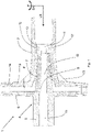
- a preferred embodiment of the invention is based on the appended figure 1 explained.
- the part of the wheelset shaft shown corresponds to the device 1 according to the invention, which is preferably designed to be rotationally symmetrical.
- the device 1 initially comprises an axle tube 2 extending in the longitudinal direction LR.
- the walls of the axle tube 2 are preferably cast from a cast aluminum alloy, preferably from AlSi7Mg0.3 or AlCu4Ti.
- the casting condition or material condition preferably corresponds to ST6.
- the production of higher mechanical properties on the component is supported by casting technology.
- the axle tube 2 is initially hollow on the inside in the longitudinal direction.
- 2 struts can be arranged in the axle tube.
- the axle tube 2 of the device 1 extends further in the opposite direction to the longitudinal direction LR and forms a first end section of a wheel set shaft that is not shown in full.
- the wheelset shaft merges into an axle tube of a second device rotated by 180° as a mirror image to an axis of rotation DA—the axis of rotation being oriented perpendicularly to the longitudinal direction LR.
- the second device is therefore also part of the axle. Due to symmetry, it is constructed identically to the first device 1, with the longitudinal direction of the second device—corresponding to the orientation of the second device 1 rotated relative to the first device 1—opposite to the longitudinal direction LR of the first device 1 being aligned as a mirror image.
- the wheelset shaft with the first device 1 and the second device can be stored in a wheel set bearing, not shown.
- the axle tube 2 of the device 1 ends in the longitudinal direction LR in a first wheel flange 3.
- the first wheel flange 3 is preferably designed like a plate and is connected to a wheel 8, a wheel hub 9 and a second wheel flange 6 via a screw connection.
- the wheel hub 9 with an adapted collar sits on a mandrel 7 and is guided with a fit at the end of the aluminum axle.
- the first wheel flange 3 and the tube wall of the axle tube 2 are designed in such a way that the loads can be optimally absorbed by the component.
- Opposite the wheel hub 9, the wheel flange 6 is firmly screwed to the wheel 8. Low-wear materials can be used there to reduce noise and impact.
- a second wheel flange 6 with a wheel bearing and cone (mandrel) is arranged opposite the first wheel flange 3 .
- the second wheel flange 6 is preferably also designed in the manner of a plate and is flanged to the wheel 8 on the side of the wheel 8 opposite the first wheel flange 3 .
- the second wheel flange 6, the wheel 8 and the first wheel flange 3 are firmly connected to one another by means of a number of bolts 14 which are correct for calculation and which extend through the first wheel flange 6, the wheel 8 and the second wheel flange 3.
- other known, releasable connection means can also be used instead of a screw 14 in accordance with the concept of the invention.
- the wheel mount 4 comprises a wheel bearing 5 and a mandrel 7.
- the wheel mount 4 is preferably designed in one piece.
- the wheel mount 4 is made of steel or other materials that meet the mechanical requirements as a cast part.
- the mandrel 7 of the wheel mount 4 is designed as a cone and is arranged at the level of the wheel hub 9 of the wheel 8 . It extends in the opposite direction to the longitudinal direction LR through the wheel hub 9 of the wheel 8 into an interior space of the axle tube 2 . It is connected to the wheel hub 9 of the wheel 8 in a form-fitting manner. In the interior of the axle tube 2 it rests against the inner walls of the axle tube 2 . Therefore, at least in the area of the mandrel 7, the material thickness of the walls of the axle tube 2 varies in such a way that the diameter of the interior of the axle tube 2 adapts to the diameter of the tapering mandrel 7 accordingly.
- the mandrel 7 ends with a tolerance at a fastening element 11 cast inside the axle tube 2, which is discussed further below.
- the wheel mount 4 is provided with a bore which is used for the fixed connection, preferably a screw connection, of the wheel mount 4 with the cast-in part 11 as a fastening element.
- the screw connection is carried out with a spring-loaded washer in order to compensate for the different coefficients of expansion in the event of temperature changes (not shown).
- support ribs are arranged on the outer sides of the axle tube 2 between the axle tube 2 running in the longitudinal direction LR and the first wheel flange 3 extending vertically to the longitudinal direction LR. These serve to stabilize against loads and forces that act in the longitudinal and transverse directions on the first and second wheel flanges 3, 6 with the wheel 8 that can be arranged in between.
- the position and size of the optional support ribs are to be arranged and designed depending on the calculation and the space available.
- the wheel 8 is a turned part made of steel and can be made separately from normal round steel.
- the centrally arranged axle tube 2 with wheel flanges 3, 6 on both sides accommodates the wheels 8 on both sides, the wheels 8 being screwed to the axle tube 2 via the mandrel 7 designed as a cone with the wheel bearings 5 and the wheel flanges 3, 6.
Landscapes
- Engineering & Computer Science (AREA)
- Mechanical Engineering (AREA)
- Vehicle Body Suspensions (AREA)
- Shafts, Cranks, Connecting Bars, And Related Bearings (AREA)
- Arrangement And Driving Of Transmission Devices (AREA)
Applications Claiming Priority (2)
| Application Number | Priority Date | Filing Date | Title |
|---|---|---|---|
| DE202018105052.4U DE202018105052U1 (de) | 2018-09-05 | 2018-09-05 | Vorrichtung sowie eine Radsatzwelle für Schienenfahrzeuge |
| PCT/EP2019/072787 WO2020048820A1 (de) | 2018-09-05 | 2019-08-27 | Vorrichtung sowie eine radsatzwelle für schienenfahrzeuge |
Publications (2)
| Publication Number | Publication Date |
|---|---|
| EP3847041A1 EP3847041A1 (de) | 2021-07-14 |
| EP3847041B1 true EP3847041B1 (de) | 2022-10-19 |
Family
ID=67809454
Family Applications (1)
| Application Number | Title | Priority Date | Filing Date |
|---|---|---|---|
| EP19761802.8A Active EP3847041B1 (de) | 2018-09-05 | 2019-08-27 | Vorrichtung sowie eine radsatzwelle für schienenfahrzeuge |
Country Status (13)
| Country | Link |
|---|---|
| US (1) | US12194780B2 (pl) |
| EP (1) | EP3847041B1 (pl) |
| CN (1) | CN112654511A (pl) |
| CA (1) | CA3110036A1 (pl) |
| DE (1) | DE202018105052U1 (pl) |
| DK (1) | DK3847041T3 (pl) |
| ES (1) | ES2936245T3 (pl) |
| FI (1) | FI3847041T3 (pl) |
| HU (1) | HUE060737T2 (pl) |
| MX (1) | MX2021002591A (pl) |
| PL (1) | PL3847041T3 (pl) |
| PT (1) | PT3847041T (pl) |
| WO (1) | WO2020048820A1 (pl) |
Family Cites Families (18)
| Publication number | Priority date | Publication date | Assignee | Title |
|---|---|---|---|---|
| US177581A (en) * | 1876-05-16 | Improvement in securing wheels to axles | ||
| US50579A (en) * | 1865-10-24 | Improved car-wheel | ||
| DE658358C (de) * | 1938-03-26 | Fried Krupp Akt Ges | Leichtradsatz fuer Schienenfahrzeuge | |
| US793311A (en) * | 1904-07-18 | 1905-06-27 | David A Moore | Wheel. |
| US929347A (en) * | 1909-03-16 | 1909-07-27 | Israel P Todd | Car-wheel. |
| US1224760A (en) * | 1916-06-30 | 1917-05-01 | American Car & Foundry Co | Tight and loose running-gear. |
| US1395913A (en) * | 1918-04-15 | 1921-11-01 | Ford Henry | Hub construction |
| US1381635A (en) * | 1919-10-04 | 1921-06-14 | Hannegan Joseph Leroy | Hub-flange for motor-vehicles |
| US1488758A (en) * | 1923-06-26 | 1924-04-01 | Letora Edward | Wheel hub |
| AT113383B (de) * | 1928-07-23 | 1929-05-25 | Skf Svenska Kullagerfab Ab | Achsbüchse mit zwei oder mehreren Rollenlagern, insbesondere für Schienenfahrzeuge. |
| DE569368C (de) * | 1930-09-07 | 1933-02-02 | Ver Kugellagerfabriken Akt Ges | Waelzlagerung von Achsen und Wellen, vorzugsweise fuer Achslagerungen von Schienenfahrzeugen |
| US2013139A (en) * | 1934-01-18 | 1935-09-03 | Rice Charles De Los | Vehicle wheel |
| US2052702A (en) * | 1935-01-02 | 1936-09-01 | Timken Roller Bearing Co | Roller bearing axle |
| CH296879A (de) * | 1950-08-05 | 1954-02-28 | Timken Roller Bearing Co | Achslager mit Achse für ein Fahrzeug. |
| AT385616B (de) | 1983-03-30 | 1988-04-25 | Schrack Elektronik Ag | Tastwahlblock, z.b. fuer fernsprechapparate, vermittlungstische, datenterminals od.dgl. |
| DE3931912A1 (de) * | 1989-09-25 | 1991-04-04 | Eickhoff Geb | Einzelradlagerung eines triebrades an schienenfahrzeugen |
| US6623057B1 (en) * | 1998-01-08 | 2003-09-23 | Thomas W. Blasingame | Uni-directional lockout for railroad car wheelset differential |
| DE102014000641A1 (de) * | 2014-01-16 | 2015-07-16 | Innotec Lightweight Engineering & Polymer Technology Gmbh | Radsatzwelle und Radsatz sowie Verfahren zu ihrer Herstellung |
-
2018
- 2018-09-05 DE DE202018105052.4U patent/DE202018105052U1/de not_active Expired - Lifetime
-
2019
- 2019-08-27 US US17/272,365 patent/US12194780B2/en active Active
- 2019-08-27 PL PL19761802.8T patent/PL3847041T3/pl unknown
- 2019-08-27 EP EP19761802.8A patent/EP3847041B1/de active Active
- 2019-08-27 PT PT197618028T patent/PT3847041T/pt unknown
- 2019-08-27 CA CA3110036A patent/CA3110036A1/en active Pending
- 2019-08-27 DK DK19761802.8T patent/DK3847041T3/da active
- 2019-08-27 ES ES19761802T patent/ES2936245T3/es active Active
- 2019-08-27 WO PCT/EP2019/072787 patent/WO2020048820A1/de not_active Ceased
- 2019-08-27 MX MX2021002591A patent/MX2021002591A/es unknown
- 2019-08-27 CN CN201980058134.XA patent/CN112654511A/zh active Pending
- 2019-08-27 HU HUE19761802A patent/HUE060737T2/hu unknown
- 2019-08-27 FI FIEP19761802.8T patent/FI3847041T3/fi active
Also Published As
| Publication number | Publication date |
|---|---|
| ES2936245T3 (es) | 2023-03-15 |
| CN112654511A (zh) | 2021-04-13 |
| CA3110036A1 (en) | 2020-03-12 |
| EP3847041A1 (de) | 2021-07-14 |
| US20210323350A1 (en) | 2021-10-21 |
| WO2020048820A1 (de) | 2020-03-12 |
| DK3847041T3 (da) | 2023-01-30 |
| MX2021002591A (es) | 2021-05-12 |
| PL3847041T3 (pl) | 2023-03-13 |
| FI3847041T3 (fi) | 2023-01-31 |
| HUE060737T2 (hu) | 2023-04-28 |
| US12194780B2 (en) | 2025-01-14 |
| DE202018105052U1 (de) | 2019-12-09 |
| PT3847041T (pt) | 2023-01-24 |
Similar Documents
| Publication | Publication Date | Title |
|---|---|---|
| EP2736733B1 (de) | Fahrwerksystem für nutzfahrzeuge | |
| EP0904956B1 (de) | Baueinheit für Kraftfahrzeugräder | |
| DE102011079979A1 (de) | Verbundlenkerachse | |
| EP2697108B1 (de) | Drehmomentenstütze sowie drehgestell für ein schienenfahrzeug | |
| DE19929390A1 (de) | Bremsscheibe | |
| WO2007098927A1 (de) | Gusslenker mit integrierter stahlbuchse | |
| AT524322B1 (de) | Gleitlagerung | |
| DE3544222A1 (de) | Differentialachse fuer eisenbahnwagen | |
| EP3573844B1 (de) | Rad für schienenfahrzeuge | |
| DE102009033353B4 (de) | Radsatz mit Scheibenrädern für Hochgeschwindigkeitszüge | |
| EP3941795B1 (de) | Fahrwerk für ein schienenfahrzeug sowie schienenfahrzeugwagen mit mindestens einem fahrwerk, schienenfahrzeug mit mindestens einem schienenfahrzeugwagen und verfahren zur höheneinstellung eines wagenkastens eines schienenfahrzeugwagens | |
| EP3847041B1 (de) | Vorrichtung sowie eine radsatzwelle für schienenfahrzeuge | |
| DE102014218323B4 (de) | Achseinheit | |
| EP3191326B1 (de) | Achseinheit | |
| WO2017080794A1 (de) | Radlagervorrichtung, sowie verfahren zur montage einer radlagervorrichtung | |
| DE10141402A1 (de) | Radnaben-Einheit und Achsschenkel für die Radaufhängung eines Kraftfahrzeuges sowie Verfahren für deren Herstellung | |
| DE102018129285A1 (de) | Radlager für ein Kraftfahrzeug | |
| DE102019100271B4 (de) | Achsträger für ein Kraftfahrzeug | |
| EP2417360A1 (de) | Verstärkungselement zur verwendung mit einer ventilatornabe | |
| DE4225903C2 (de) | Radadapter für Lastfahrzeugräder | |
| DE102006025555A1 (de) | Radkopf | |
| DE2005949A1 (de) | Laufradantrieb und Lagerung fur einen Kran | |
| DE102022108029B3 (de) | Radnabe und zugehöriges Kraftfahrzeug | |
| EP1149009A1 (de) | Losradachse für schienenfahrzeuge | |
| DE2922407C2 (de) | Laufradanordnung für Kran- und Katzlaufwerke |
Legal Events
| Date | Code | Title | Description |
|---|---|---|---|
| STAA | Information on the status of an ep patent application or granted ep patent |
Free format text: STATUS: UNKNOWN |
|
| STAA | Information on the status of an ep patent application or granted ep patent |
Free format text: STATUS: THE INTERNATIONAL PUBLICATION HAS BEEN MADE |
|
| PUAI | Public reference made under article 153(3) epc to a published international application that has entered the european phase |
Free format text: ORIGINAL CODE: 0009012 |
|
| STAA | Information on the status of an ep patent application or granted ep patent |
Free format text: STATUS: REQUEST FOR EXAMINATION WAS MADE |
|
| 17P | Request for examination filed |
Effective date: 20210329 |
|
| AK | Designated contracting states |
Kind code of ref document: A1 Designated state(s): AL AT BE BG CH CY CZ DE DK EE ES FI FR GB GR HR HU IE IS IT LI LT LU LV MC MK MT NL NO PL PT RO RS SE SI SK SM TR |
|
| DAV | Request for validation of the european patent (deleted) | ||
| DAX | Request for extension of the european patent (deleted) | ||
| GRAP | Despatch of communication of intention to grant a patent |
Free format text: ORIGINAL CODE: EPIDOSNIGR1 |
|
| STAA | Information on the status of an ep patent application or granted ep patent |
Free format text: STATUS: GRANT OF PATENT IS INTENDED |
|
| INTG | Intention to grant announced |
Effective date: 20220613 |
|
| GRAS | Grant fee paid |
Free format text: ORIGINAL CODE: EPIDOSNIGR3 |
|
| GRAA | (expected) grant |
Free format text: ORIGINAL CODE: 0009210 |
|
| STAA | Information on the status of an ep patent application or granted ep patent |
Free format text: STATUS: THE PATENT HAS BEEN GRANTED |
|
| AK | Designated contracting states |
Kind code of ref document: B1 Designated state(s): AL AT BE BG CH CY CZ DE DK EE ES FI FR GB GR HR HU IE IS IT LI LT LU LV MC MK MT NL NO PL PT RO RS SE SI SK SM TR |
|
| REG | Reference to a national code |
Ref country code: GB Ref legal event code: FG4D Free format text: NOT ENGLISH |
|
| REG | Reference to a national code |
Ref country code: CH Ref legal event code: EP |
|
| REG | Reference to a national code |
Ref country code: IE Ref legal event code: FG4D Free format text: LANGUAGE OF EP DOCUMENT: GERMAN |
|
| REG | Reference to a national code |
Ref country code: DE Ref legal event code: R096 Ref document number: 502019005982 Country of ref document: DE |
|
| REG | Reference to a national code |
Ref country code: AT Ref legal event code: REF Ref document number: 1525346 Country of ref document: AT Kind code of ref document: T Effective date: 20221115 |
|
| REG | Reference to a national code |
Ref country code: PT Ref legal event code: SC4A Ref document number: 3847041 Country of ref document: PT Date of ref document: 20230124 Kind code of ref document: T Free format text: AVAILABILITY OF NATIONAL TRANSLATION Effective date: 20230118 Ref country code: FI Ref legal event code: FGE |
|
| REG | Reference to a national code |
Ref country code: NL Ref legal event code: FP |
|
| REG | Reference to a national code |
Ref country code: DK Ref legal event code: T3 Effective date: 20230123 |
|
| REG | Reference to a national code |
Ref country code: SE Ref legal event code: TRGR |
|
| REG | Reference to a national code |
Ref country code: LT Ref legal event code: MG9D |
|
| REG | Reference to a national code |
Ref country code: NO Ref legal event code: T2 Effective date: 20221019 |
|
| REG | Reference to a national code |
Ref country code: ES Ref legal event code: FG2A Ref document number: 2936245 Country of ref document: ES Kind code of ref document: T3 Effective date: 20230315 |
|
| PG25 | Lapsed in a contracting state [announced via postgrant information from national office to epo] |
Ref country code: LT Free format text: LAPSE BECAUSE OF FAILURE TO SUBMIT A TRANSLATION OF THE DESCRIPTION OR TO PAY THE FEE WITHIN THE PRESCRIBED TIME-LIMIT Effective date: 20221019 |
|
| REG | Reference to a national code |
Ref country code: HU Ref legal event code: AG4A Ref document number: E060737 Country of ref document: HU |
|
| PG25 | Lapsed in a contracting state [announced via postgrant information from national office to epo] |
Ref country code: RS Free format text: LAPSE BECAUSE OF FAILURE TO SUBMIT A TRANSLATION OF THE DESCRIPTION OR TO PAY THE FEE WITHIN THE PRESCRIBED TIME-LIMIT Effective date: 20221019 Ref country code: LV Free format text: LAPSE BECAUSE OF FAILURE TO SUBMIT A TRANSLATION OF THE DESCRIPTION OR TO PAY THE FEE WITHIN THE PRESCRIBED TIME-LIMIT Effective date: 20221019 Ref country code: IS Free format text: LAPSE BECAUSE OF FAILURE TO SUBMIT A TRANSLATION OF THE DESCRIPTION OR TO PAY THE FEE WITHIN THE PRESCRIBED TIME-LIMIT Effective date: 20230219 Ref country code: HR Free format text: LAPSE BECAUSE OF FAILURE TO SUBMIT A TRANSLATION OF THE DESCRIPTION OR TO PAY THE FEE WITHIN THE PRESCRIBED TIME-LIMIT Effective date: 20221019 Ref country code: GR Free format text: LAPSE BECAUSE OF FAILURE TO SUBMIT A TRANSLATION OF THE DESCRIPTION OR TO PAY THE FEE WITHIN THE PRESCRIBED TIME-LIMIT Effective date: 20230120 |
|
| REG | Reference to a national code |
Ref country code: DE Ref legal event code: R097 Ref document number: 502019005982 Country of ref document: DE |
|
| PG25 | Lapsed in a contracting state [announced via postgrant information from national office to epo] |
Ref country code: SM Free format text: LAPSE BECAUSE OF FAILURE TO SUBMIT A TRANSLATION OF THE DESCRIPTION OR TO PAY THE FEE WITHIN THE PRESCRIBED TIME-LIMIT Effective date: 20221019 Ref country code: RO Free format text: LAPSE BECAUSE OF FAILURE TO SUBMIT A TRANSLATION OF THE DESCRIPTION OR TO PAY THE FEE WITHIN THE PRESCRIBED TIME-LIMIT Effective date: 20221019 Ref country code: EE Free format text: LAPSE BECAUSE OF FAILURE TO SUBMIT A TRANSLATION OF THE DESCRIPTION OR TO PAY THE FEE WITHIN THE PRESCRIBED TIME-LIMIT Effective date: 20221019 |
|
| PLBE | No opposition filed within time limit |
Free format text: ORIGINAL CODE: 0009261 |
|
| STAA | Information on the status of an ep patent application or granted ep patent |
Free format text: STATUS: NO OPPOSITION FILED WITHIN TIME LIMIT |
|
| PG25 | Lapsed in a contracting state [announced via postgrant information from national office to epo] |
Ref country code: SK Free format text: LAPSE BECAUSE OF FAILURE TO SUBMIT A TRANSLATION OF THE DESCRIPTION OR TO PAY THE FEE WITHIN THE PRESCRIBED TIME-LIMIT Effective date: 20221019 Ref country code: AL Free format text: LAPSE BECAUSE OF FAILURE TO SUBMIT A TRANSLATION OF THE DESCRIPTION OR TO PAY THE FEE WITHIN THE PRESCRIBED TIME-LIMIT Effective date: 20221019 |
|
| 26N | No opposition filed |
Effective date: 20230720 |
|
| PG25 | Lapsed in a contracting state [announced via postgrant information from national office to epo] |
Ref country code: SI Free format text: LAPSE BECAUSE OF FAILURE TO SUBMIT A TRANSLATION OF THE DESCRIPTION OR TO PAY THE FEE WITHIN THE PRESCRIBED TIME-LIMIT Effective date: 20221019 |
|
| PG25 | Lapsed in a contracting state [announced via postgrant information from national office to epo] |
Ref country code: MC Free format text: LAPSE BECAUSE OF FAILURE TO SUBMIT A TRANSLATION OF THE DESCRIPTION OR TO PAY THE FEE WITHIN THE PRESCRIBED TIME-LIMIT Effective date: 20221019 |
|
| PG25 | Lapsed in a contracting state [announced via postgrant information from national office to epo] |
Ref country code: MC Free format text: LAPSE BECAUSE OF FAILURE TO SUBMIT A TRANSLATION OF THE DESCRIPTION OR TO PAY THE FEE WITHIN THE PRESCRIBED TIME-LIMIT Effective date: 20221019 |
|
| PG25 | Lapsed in a contracting state [announced via postgrant information from national office to epo] |
Ref country code: LU Free format text: LAPSE BECAUSE OF NON-PAYMENT OF DUE FEES Effective date: 20230827 |
|
| PG25 | Lapsed in a contracting state [announced via postgrant information from national office to epo] |
Ref country code: LU Free format text: LAPSE BECAUSE OF NON-PAYMENT OF DUE FEES Effective date: 20230827 |
|
| REG | Reference to a national code |
Ref country code: IE Ref legal event code: MM4A |
|
| PG25 | Lapsed in a contracting state [announced via postgrant information from national office to epo] |
Ref country code: IE Free format text: LAPSE BECAUSE OF NON-PAYMENT OF DUE FEES Effective date: 20230827 |
|
| PG25 | Lapsed in a contracting state [announced via postgrant information from national office to epo] |
Ref country code: IE Free format text: LAPSE BECAUSE OF NON-PAYMENT OF DUE FEES Effective date: 20230827 |
|
| PG25 | Lapsed in a contracting state [announced via postgrant information from national office to epo] |
Ref country code: BG Free format text: LAPSE BECAUSE OF FAILURE TO SUBMIT A TRANSLATION OF THE DESCRIPTION OR TO PAY THE FEE WITHIN THE PRESCRIBED TIME-LIMIT Effective date: 20221019 |
|
| PG25 | Lapsed in a contracting state [announced via postgrant information from national office to epo] |
Ref country code: BG Free format text: LAPSE BECAUSE OF FAILURE TO SUBMIT A TRANSLATION OF THE DESCRIPTION OR TO PAY THE FEE WITHIN THE PRESCRIBED TIME-LIMIT Effective date: 20221019 |
|
| PG25 | Lapsed in a contracting state [announced via postgrant information from national office to epo] |
Ref country code: CY Free format text: LAPSE BECAUSE OF FAILURE TO SUBMIT A TRANSLATION OF THE DESCRIPTION OR TO PAY THE FEE WITHIN THE PRESCRIBED TIME-LIMIT; INVALID AB INITIO Effective date: 20190827 |
|
| PGFP | Annual fee paid to national office [announced via postgrant information from national office to epo] |
Ref country code: NL Payment date: 20250821 Year of fee payment: 7 |
|
| PGFP | Annual fee paid to national office [announced via postgrant information from national office to epo] |
Ref country code: HU Payment date: 20250822 Year of fee payment: 7 |
|
| PGFP | Annual fee paid to national office [announced via postgrant information from national office to epo] |
Ref country code: FI Payment date: 20250820 Year of fee payment: 7 Ref country code: ES Payment date: 20250917 Year of fee payment: 7 Ref country code: PT Payment date: 20250818 Year of fee payment: 7 |
|
| PGFP | Annual fee paid to national office [announced via postgrant information from national office to epo] |
Ref country code: DK Payment date: 20250821 Year of fee payment: 7 Ref country code: DE Payment date: 20250806 Year of fee payment: 7 |
|
| PGFP | Annual fee paid to national office [announced via postgrant information from national office to epo] |
Ref country code: NO Payment date: 20250820 Year of fee payment: 7 |
|
| PGFP | Annual fee paid to national office [announced via postgrant information from national office to epo] |
Ref country code: PL Payment date: 20250801 Year of fee payment: 7 Ref country code: TR Payment date: 20250820 Year of fee payment: 7 Ref country code: IT Payment date: 20250829 Year of fee payment: 7 |
|
| PGFP | Annual fee paid to national office [announced via postgrant information from national office to epo] |
Ref country code: BE Payment date: 20250820 Year of fee payment: 7 Ref country code: GB Payment date: 20250822 Year of fee payment: 7 |
|
| PGFP | Annual fee paid to national office [announced via postgrant information from national office to epo] |
Ref country code: AT Payment date: 20250819 Year of fee payment: 7 Ref country code: FR Payment date: 20250821 Year of fee payment: 7 |
|
| PGFP | Annual fee paid to national office [announced via postgrant information from national office to epo] |
Ref country code: CH Payment date: 20250901 Year of fee payment: 7 Ref country code: SE Payment date: 20250821 Year of fee payment: 7 |
|
| PGFP | Annual fee paid to national office [announced via postgrant information from national office to epo] |
Ref country code: CZ Payment date: 20250814 Year of fee payment: 7 |