EP3847028B1 - Method for distortion-free and homogeneous coating of workpieces having bidirectionally curved surfaces - Google Patents
Method for distortion-free and homogeneous coating of workpieces having bidirectionally curved surfaces Download PDFInfo
- Publication number
- EP3847028B1 EP3847028B1 EP19761841.6A EP19761841A EP3847028B1 EP 3847028 B1 EP3847028 B1 EP 3847028B1 EP 19761841 A EP19761841 A EP 19761841A EP 3847028 B1 EP3847028 B1 EP 3847028B1
- Authority
- EP
- European Patent Office
- Prior art keywords
- raster
- coating
- trajectory
- areas
- area
- Prior art date
- Legal status (The legal status is an assumption and is not a legal conclusion. Google has not performed a legal analysis and makes no representation as to the accuracy of the status listed.)
- Active
Links
- 238000000576 coating method Methods 0.000 title claims description 109
- 239000011248 coating agent Substances 0.000 title claims description 91
- 238000000034 method Methods 0.000 title claims description 73
- 239000013598 vector Substances 0.000 claims description 44
- 238000005034 decoration Methods 0.000 claims description 14
- 230000000295 complement effect Effects 0.000 claims description 10
- 230000001419 dependent effect Effects 0.000 claims description 7
- FGUUSXIOTUKUDN-IBGZPJMESA-N C1(=CC=CC=C1)N1C2=C(NC([C@H](C1)NC=1OC(=NN=1)C1=CC=CC=C1)=O)C=CC=C2 Chemical compound C1(=CC=CC=C1)N1C2=C(NC([C@H](C1)NC=1OC(=NN=1)C1=CC=CC=C1)=O)C=CC=C2 FGUUSXIOTUKUDN-IBGZPJMESA-N 0.000 claims description 3
- 230000008569 process Effects 0.000 description 9
- 230000006978 adaptation Effects 0.000 description 5
- 239000010410 layer Substances 0.000 description 3
- 239000002346 layers by function Substances 0.000 description 3
- 239000007788 liquid Substances 0.000 description 3
- 230000003287 optical effect Effects 0.000 description 3
- 230000009467 reduction Effects 0.000 description 3
- 230000008859 change Effects 0.000 description 2
- 230000000694 effects Effects 0.000 description 2
- 239000011159 matrix material Substances 0.000 description 2
- 238000012545 processing Methods 0.000 description 2
- 239000007787 solid Substances 0.000 description 2
- 230000007704 transition Effects 0.000 description 2
- 230000000007 visual effect Effects 0.000 description 2
- 241000288673 Chiroptera Species 0.000 description 1
- 238000013459 approach Methods 0.000 description 1
- 230000009286 beneficial effect Effects 0.000 description 1
- 230000002457 bidirectional effect Effects 0.000 description 1
- 150000001875 compounds Chemical class 0.000 description 1
- 238000012937 correction Methods 0.000 description 1
- 238000004049 embossing Methods 0.000 description 1
- 230000002349 favourable effect Effects 0.000 description 1
- 239000012530 fluid Substances 0.000 description 1
- 239000011888 foil Substances 0.000 description 1
- 230000001788 irregular Effects 0.000 description 1
- 238000012804 iterative process Methods 0.000 description 1
- 239000000463 material Substances 0.000 description 1
- 238000005259 measurement Methods 0.000 description 1
- 239000003973 paint Substances 0.000 description 1
- 230000008092 positive effect Effects 0.000 description 1
- 238000007789 sealing Methods 0.000 description 1
- 238000010561 standard procedure Methods 0.000 description 1
- 239000000126 substance Substances 0.000 description 1
- 238000012546 transfer Methods 0.000 description 1
Images


Classifications
-
- B—PERFORMING OPERATIONS; TRANSPORTING
- B41—PRINTING; LINING MACHINES; TYPEWRITERS; STAMPS
- B41J—TYPEWRITERS; SELECTIVE PRINTING MECHANISMS, i.e. MECHANISMS PRINTING OTHERWISE THAN FROM A FORME; CORRECTION OF TYPOGRAPHICAL ERRORS
- B41J3/00—Typewriters or selective printing or marking mechanisms characterised by the purpose for which they are constructed
- B41J3/407—Typewriters or selective printing or marking mechanisms characterised by the purpose for which they are constructed for marking on special material
- B41J3/4073—Printing on three-dimensional objects not being in sheet or web form, e.g. spherical or cubic objects
-
- B—PERFORMING OPERATIONS; TRANSPORTING
- B25—HAND TOOLS; PORTABLE POWER-DRIVEN TOOLS; MANIPULATORS
- B25J—MANIPULATORS; CHAMBERS PROVIDED WITH MANIPULATION DEVICES
- B25J9/00—Programme-controlled manipulators
- B25J9/16—Programme controls
- B25J9/1679—Programme controls characterised by the tasks executed
-
- G—PHYSICS
- G06—COMPUTING; CALCULATING OR COUNTING
- G06K—GRAPHICAL DATA READING; PRESENTATION OF DATA; RECORD CARRIERS; HANDLING RECORD CARRIERS
- G06K15/00—Arrangements for producing a permanent visual presentation of the output data, e.g. computer output printers
- G06K15/02—Arrangements for producing a permanent visual presentation of the output data, e.g. computer output printers using printers
- G06K15/021—Adaptations for printing on specific media
Definitions
- the invention relates to a method for the distortion-free and uniform coating of workpieces with bidirectionally curved surfaces.
- the workpiece surface is divided into grid areas on the basis of provided digital 2D decorative data and digital 3D surface profile data of a workpiece to be coated; the workpiece surface is divided into one or more traverse paths of a coating head; projects the raster areas onto the printhead trajectory along the trajectory normal vector; the 2D decor print data of the decor is adjusted for each grid area as a function of the results of the grid projection and the workpiece surface is coated on the basis of the adjusted print data.
- the present invention relates to a system for carrying out the method according to the invention.
- a possible solution for mass-produced products with "constant" but non-planar surface geometry, such as simply curved coffee cups with a constant radius, is that a uniform coating process can be ensured relatively easily by adapting the print head to the specific surface geometry of the product.
- a uniform coating process can be ensured relatively easily by adapting the print head to the specific surface geometry of the product.
- no suitable adjustment can be made by adapting the print head geometry with reasonable technical effort, especially for small series more can be achieved.
- the US 5,831,641A describe a method and apparatus for embossing high quality images onto non-planar surfaces, including the surfaces of various types of three-dimensional objects, such as baseball bats, formed from a number of different types of materials. Be in the process printed the non-planar surfaces of the three-dimensional articles using a uniquely modified inkjet image transfer technique.
- the apparatus of the invention includes a modified inkjet printer connected to a novel article positioning device that automatically maintains the surface of the article to be printed in a plane of the inkjet printer that is substantially parallel and slightly spaced from where the inkjet nozzles are located.
- the DE 1020 1200 6371 A1 describes a coating process.
- the method includes providing an image and performing a three-dimensional (3D) measurement process in an area. Space points are generated according to the region. A 3D mesh is generated according to the region. 3D web data is generated to drive a robot, e.g. B. a swing arm robot to move for an inkjet print head. Raster data, ie 3D or higher dimensional raster matrix data, is generated to drive the inkjet printhead. The robot is moved using the web data. The image is printed with the inkjet print head using the raster data.
- the EP 2 213 462 A1 an apparatus for applying liquid droplets to a surface.
- the apparatus includes a feeding device for feeding an object to an application device and a controller for controlling the feeding device, an image storage device and the application device.
- the controller has a detector device for detecting part of a three-dimensional structure of the object, the detector device being attached to the image storage device and/or the application device.
- the controller controls the application of fluid drops to the object corresponding to a print motif as a function of the detected three-dimensional structure.
- the method according to the invention is capable of coating even very irregular and strongly curved 3D surfaces in a reproducible manner, without layer thickness deviations and without distortion.
- the proposed geometrically-related adjustment means that significantly fewer traverse paths of the print head per surface unit have to be planned.
- Unfavorable angular edge areas can also be recorded and coated within a traversing path.
- the effective pressure range of a traversing path is thus increased while the coating quality remains the same, since the adjustment counteracts the distortions in the areas of "unfavorable" surface geometries.
- the effective coating area can be increased over a traversing path, so that the coating head has to travel a shorter distance to completely coat the surface.
- Distortion-free coating is made possible by the method according to the invention. Due to curved surfaces, and in particular surfaces that are curved in more than one direction, the different alignment of the respective nozzles of a coating head to the underlying surface and based on the different surface sections covered per unit of time (see Fig Figures 1-3 ) to fluctuations in coating density. This is also due to the fact that the coating head usually moves at a constant speed over the workpiece surface and a planar alignment of the coating nozzles of the coating head and a 2-dimensional working method.
- the 2-dimensional mode of operation of the print head is understood to mean that print information is only processed according to the length and width information of the image data. Height differences or distance differences due to deviating Z values covered are not taken into account.
- the surface data are provided to the print head as 2-dimensional data sets and must be applied to a 3-dimensional surface.
- the use of 3-dimensional surface data is also known, but cannot be used due to the 2-dimensional mode of operation of the printing units. Both effects lead to a homogeneous coating density on planar surfaces and to distortions in the coating density on 3D bidirectionally curved surfaces.
- 3-dimensional workpieces can be coated using the method according to the invention.
- 3D workpieces are workpieces which, at least in sections, have a non-planar surface.
- the workpiece surface therefore has differences in height and differences in the slope of the surface. Due to the differences in height and the slope of the surface, the surface of the workpiece is curved.
- the workpieces can partially have bidirectionally curved surfaces.
- a surface is bidirectionally curved within the meaning of the invention if part of the surface has a curvature in the mathematical sense in at least two different directions. Examples of such surface geometries are given in the figures.
- step a digital 2D data of a decoration to be applied and digital 3D surface profile data of a workpiece to be coated are provided.
- data for the existing coating situation is provided.
- the data can be collected on site or made available, for example, by a database.
- the surface profile data can be collected, for example, by a scanning process, for example by laser scanning.
- the surface profile data contain at least the surface profile of the workpiece, for example as an XYZ matrix, with X, Y, Z as location coordinates.
- the decor may represent a complex image, a geometric figure, or one or more lines.
- the decoration is applied to at least part of the surface of the workpiece.
- the decor not only includes the provision of optical image data.
- the term decor also includes functional coatings that are applied to the workpiece surface.
- the decor not only includes a visual impression, but can also provide other functional properties, such as switches, luminous surfaces or haptic properties.
- the decorative data include at least both the position and the volume quantity to be applied to the position data.
- the decoration is understood to mean optical as well as functional layered areas on the surface of the work.
- the workpiece surface is divided into areas of a grid, with the individual areas of the grid consisting of a polyline of equidistant lines at a distance X 0 parallel to an X and a further polyline, orthogonal thereto, of equidistant lines at a distance Y 0 parallel to a Y -direction to be trained.
- the workpiece surface is thus divided into square or rectangular grids, with the grid dimension being the same or different for both directions.
- the grid dimension ie the distance between two adjacent lines of the same train, can be 1 mm to 10 cm, for example.
- the measure can be selected as a function of the occurring surface geometry of the workpiece and overall as a function of its spatial dimensions.
- Workpieces with 3D surface deviations on small length scales may preferably require a small grid dimension. If the 3D properties of the workpiece are on larger length scales, a larger grid may be appropriate.
- the definition of the XY coordinate system can be chosen as a function of the surface symmetry of the workpiece.
- a polyline consists of at least two parallel lines.
- step c) the workpiece surface is divided into one or more traversing paths of a coating head, with the traversing paths being above the workpiece surface run and the intersection lines of adjacent traversing paths at least abut one another.
- the entire workpiece surface is divided into traversing paths of a coating head, with each surface element that is to be coated being passed over at least once.
- the distance between the traversing path and the workpiece can, but does not have to, be constant. Distances between the coating head and the workpiece surface of between 2.5 mm and 5 cm have proven to be suitable.
- the line of intersection of a traversing path is the edge line of the traversing path and characterizes the outer line of the maximum coatable area of the coating head on this path.
- intersection lines meet on different traverse paths if the distance between the intersection lines of two adjacent traverse paths is less than or equal to the coating resolution.
- the individual traversing paths it is also possible for the individual traversing paths to be defined in such a way that they overlap at the edge areas, ie at the cutting lines. Possible overlapping areas of adjacent traversing paths can amount to, for example, 5-25% of the total coating head area. If the traversing path overlaps, certain surface areas of at least two traversing paths can be coated.
- step d) the lines delimiting the grid areas are projected onto one or more travel paths above the relevant grid surface, the projection taking place along the normal vector of the respective travel path.
- This raster is projected along the normal vectors of the one or more traversing paths lying above the surface section.
- the vector planes of the traversing paths with the projected grid lines and cutting lines are then transformed into a 2-dimensional form.
- the 2-dimensional traversing paths are positioned next to each other according to their positions, so that the intersection lines of the adjacent traversing paths are next to each other.
- the traversing path can be reduced to a printing path.
- the print path has the same orientation but a smaller surface area compared to the traverse path, with the nozzles at the edges of the traverse path then no longer being used for coating.
- the intersection lines of the respective adjacent print webs are evaluated to determine whether they are complementary to one another, i.e. complement each other without gaps. If the cutting lines of adjacent print webs can be continuously attached to one another, no harmonization of the image data of the print webs is required.
- These print webs can be positioned directly next to each other over the 2-dimensional image data.
- step e) the 2D decor print data for each grid area is adjusted, with the adjustment of the print data of the grid area being both a function of the originally provided 2D data of the decor and a function of the grid projection to the traversing path.
- the volume to be applied by a respective area of the print head thus results as a function of the respective deviation of the print head alignment from the surface and the intended layer volume within the respective raster area.
- the adaptation of the data of a raster area is therefore dependent on whether the decor even provides a pixel at this surface location. If the decor provides a coating at this point, then the pixel density is also corrected as a function of the surface geometry at this surface point, proportionally transformed via the projection onto the traversing path. In the case of parallel surfaces, i.e.
- the image data will now be processed in such a way that the number of printing dots is increased in accordance with the reduction in the distance between the grid lines, both in the longitudinal and in the width direction.
- the result of this resolution adjustment is that between the grid lines on the workpiece surface there is always the same number of print dots in lengthwise and widthwise direction. This can ensure an even coating that provides particularly distortion-free images and/or robust functional areas.
- the 2D decorative print data for each grid area includes at least the number of dots (pixels) to be applied in the grid and the application quantity per pixel.
- the workpiece surface is coated on the basis of the adapted decor print data.
- the coating is usually done by applying liquids to the workpiece surface.
- the liquids can be, for example, paints, surface sealing substances or other functional compounds that give the surface a different aesthetic or functional appearance.
- the coating can take place, for example, by means of an inkjet process.
- Functional layers can be produced by means of the coating, with functional layers being at least partially contiguous areas which are applied or printed onto the workpiece surface. These connected areas fulfill further functional properties on the workpiece surface.
- These functional properties can be of a haptic or visual nature, for example. Luminous areas or the application of decorations are conceivable. However, functional areas or layers are also conceivable which have specified electrical properties in the form of switches. Furthermore, functional layers can also provide other optical properties in the form of luminous areas. In addition, other haptic properties, such as a tactile relief, can also be displayed via the functional areas.
- the adjustment of the 2D decorative print data in method step e) can include the pixel density of the raster areas. Adjusting the pixel density has proven to be particularly suitable for the present method, with the number of pixels, i.e. the pixel density, being adjusted in particular in the bidirectionally curved areas. This can contribute to particularly distortion-free coatings, even on geometries that are difficult to print on.
- the adjustment of the 2D decorative print data in method step e) can include the quantity applied to the respective grid area. Adjusting the volume per grid area has proven to be particularly suitable for the present method, with the application volume of the individual pixels and thus also the application volume per grid area being adjusted to include one or more pixels in the bidirectionally curved areas in particular. This can contribute to particularly distortion-free coatings, even on geometries that are difficult to print on.
- the normal vector for each grid area from step b) can be determined in a further step.
- the grid lines divide the surface into squares or rectangles, with a surface section (grid) being delimited by 4 grid lines.
- the squares or rectangles themselves are distorted in 2 directions due to the curvature. If the distances between the grid lines remain the same, different curvatures of the partial areas lead to curvatures in the grid lines, which results in the distortion of the surfaces.
- a normal vector can be defined for this surface area, which is perpendicular to the partial surface delimited by the grid lines. If the surface itself is still curved within the grid area, the normal vector can be specified for the planar surface, for example, which intersects the curved surface in the grid and has the same volume above and below the line of intersection to the curved workpiece surface in the grid.
- the projection-dependent density adjustment in step e) can be carried out either as a function e1) of the angular deviations ⁇ (x,y) of the normal vector of the screen area in the X ( ⁇ (x)) and in the Y direction ( ⁇ (y)) to the normal vector of the trajectory; or e2) the average spacing of the grid lines in the X ( ⁇ X), in the Y direction ( ⁇ Y) or as a combination of the average spacing in the XY direction ( ⁇ XY) of the grid lines projected onto the traversing path.
- the angular deviations between the normal vector of the grid area in question and the traversing path have proven to be particularly suitable for adjusting the pixel density.
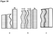
- the workpiece surface can be divided into several traversing paths in step c) sequentially, with a first traversing path D 0 being defined in a first step and the following traversing paths each being defined adjacent to the preceding traversing path in further steps, with the further traversing paths either connect seamlessly to adjacent traversing paths or be defined as overlapping with them.
- the subdivision of the workpiece surface into traversing paths can favorably take place in such a way that a first traversing path is defined and the further traversing paths on both sides of the first traversing path are connected to it without gaps.
- the traversing paths it is also possible for the traversing paths to be aligned so that they overlap, so that one and the same workpiece surface area can be coated from, for example, two different traversing paths. Determining which of the two or even both traverse paths can coat the overlapping area as a function of the existing angular deviations or based on them further considerations are made. In this way, the entire workpiece surface can be coated in an adapted manner.
- the active coating area of a traversing path can be defined in step c1) as a function of the maximum angular deviation between the normal vector of the traversing path and the normal vectors of the underlying grid areas.
- the outer areas of the traversing path have an excessively large angular deviation compared to the other coating nozzles in the "inside" of the traversing path.
- a maximum angular deviation between the normal vectors of, for example, a maximum of 25°, preferably a maximum of 20°, further preferably a maximum of 15°, can be specified, for example.
- the recessed areas would then have an adjacent, overlapping traversing path are coated.
- this division can be optimized since, by compensating for the angular deviation in the image data, travel paths can also be selected which are “less favorable” with regard to the existing angular deviations. Larger coating or printing areas can therefore be selected per traversing path, which leads to a reduction in the number of traversing paths required. This saving can result in a faster and more productive coating process.
- the alignment of the first traversing path D 0 in step c) can be selected such that the resulting sum of the angular deviations ⁇ in this direction is smaller than the sum of the angular deviations in a direction orthogonal thereto.
- the first traversing path In order to carry out a coating process that is as rapid and as symmetrical as possible, it has proven advantageous for the first traversing path to be defined in such a way that the smallest possible angular deviation is obtained over the surface to be coated. In the best case, this can result in the curving surfaces being able to be divided particularly easily on the remaining surface. This can reduce the number of traverse paths required by the coating head and contribute to a reduction in coating time while maintaining quality.
- the workpiece surface can be divided into one or more traverse paths in step c) in such a way that the total sum of the product (X 0 - ⁇ X) ⁇ (Y 0 - ⁇ Y) over the individual grids projected onto the traverse path is a each traverse results in zero.
- One way of efficiently dividing the workpiece surface into individual traversing paths can result from the traversing path covering as symmetrical a deviation as possible in both the X and Y directions. To do this, the differences between the projected grid line spacing and the original grid spacing are considered. This division can prevent the coating of a surface area with strongly asymmetrical surface properties and thus contribute to a particularly uniform coating result.
- the workpiece surface can be divided into one or more traversing paths in step c) in such a way that the total sum of the product tan ( ⁇ (x)) ⁇ tan ( ⁇ (y)) over the individual grid areas of a traversing path is results in zero.
- a further possibility for obtaining a coating result that is as uniform as possible can be that the traversing paths are defined via an angular deviation in the X and Y direction of the normal vectors of the grid areas that is as constant as possible. This selection criterion can prevent the coating from deviating too much within a traverse path and thus lead to a high-quality coating result.
- the distance between the equidistant lines of the polylines in the X (X 0 ) and in the Y direction (Y 0 ) in step b) can be greater than or equal to 0.1 mm and less than or equal to 5 mm.
- the line spacings in the different directions can be selected as a function of the size and surface curvature of the workpiece surface. In most cases, however, the range specified above for the spacing of the grid lines has proven to be particularly suitable. With these distances, a large number of different surface geometries can be provided with sufficient adaptation, so that better-quality coatings can be obtained in a shorter time.
- the distance between the equidistant lines of the polylines in the X (X 0 ) and in the Y direction (Y 0 ) in step b) can preferably be greater than or equal to 0.25 mm and less than or equal to 4.5 mm, preferably greater than or equal to 0 .3 mm and less than or equal to 4.5 mm.
- the workpiece can be printed using an inkjet method using an inkjet print head with one or more nozzles, and the pixel density can be adjusted by increasing the number of coated dots.
- the inkjet method has proven to be particularly suitable in the context of the embodiment according to the invention, since significant gains in the compensation of distortions and in the speed of printing can be achieved by means of the adaptation proposed here. Overall, these advantages can mean that bidirectional curved surfaces can be printed much more efficiently and cheaply.
- the number of coated points can be increased by adapting the pulse frequency of one or more nozzles.
- Changing the pulse frequency to adjust the density as part of an inkjet process has proven to be particularly suitable compared to changing the travel speed of the print head.
- an even coating result can be obtained by the constant speed of the coating head on the traversing path.
- the adjusted coating can take place within the original coating head speed, so that time is not wasted unnecessarily in the coating of strongly curved surfaces. In this way, the coating can be carried out extremely efficiently and inexpensively.
- the method according to the invention is used for coating automobile parts.
- Automobile interiors and also exterior parts in particular can be coated by means of the method according to the invention.
- the dimensions of the parts to be coated and the curvatures that these parts have have proven to be particularly suitable for the process.
- These parts can be coated significantly faster and with less distortion, which can contribute to significantly better aesthetics and significant savings in time and energy.
- Also according to the invention is a system for coating 3-dimensional bidirectionally curved surfaces having at least one computing unit, an actuator, an inkjet unit with at least one nozzle head and a control unit, the system being set up to carry out the method according to the invention.
- the system can have a computing unit that is able to adjust the pixel density and define the individual trajectories in real time. With fixed surface geometries and fixed decors, however, it is also possible to calculate the adjustment before the actual printing process and to supply the print head with the adjusted decor data. This can require a computing unit with a higher computing power.
- the actuators can be one or more combined X,Y or X,Y,Z arms which Execute linear and/or rotary movements in X,Y,Z and carry the print/nozzle head and/or the workpiece.
- the nozzle head can expediently carry one or more nozzles.
- the print head preferably carries a plurality of print heads arranged in rows. This can increase the coating speed.
- the control unit controls the relative movement between the head and the workpiece and can also control the coating unit, for example by pulse control of individual rows or individual nozzles.
- the system can also be set up to configure the coating process as a function of the movement of the coating head in a single-pass, multi-pass or reverse manner.
- the print head of the inkjet unit can have several rows of nozzles and the method can be carried out separately for each row of nozzles.
- the method according to the invention can be carried out with a coating head which has independently controlled rows of nozzle heads next to or behind one another.
- the method according to the invention can then be carried out for all of the nozzle heads or for the individual rows of nozzle heads.
- the adjustment can be made with respect to a normal vector of the traversing path, which is “suspended” at the center point of the rows of nozzles.
- the normal vector it is also possible for the normal vector to be "suspended" at the center point of each row of nozzles or each nozzle. This results in individual adjustments for each row of nozzles or each nozzle and in this way the decoration can be applied to the workpiece surface with even less distortion.
- the computing unit of the system can be designed to define several sets of differently running traverse paths D 0 and the respective adjacent traverse paths over the entire workpiece surface and to select that set which has the smallest number of traverse paths.
- it can be advantageous to select several starting points and directions relative to the workpiece surface for the first traverse path and, for example, as a function of the selected maximum permissible Angular deviations between the print head and the workpiece surface to define the subsequent traversing paths.
- that constellation can then be selected for the sum of traversing paths that manages with the lowest number of traversing paths and a maximum pressure range per traversing path. In this way, the coating process can be accelerated and optimized.
- the figure 1 shows schematically the possibilities for different coatings of surfaces.
- the traversing path of the coating head (represented by the solid arrow (-)) moves in these examples a) - c) parallel to the curvature of the surface of the workpiece (represented by the broken arrow (- - - - )).
- Curved surfaces are generally understood to be those surfaces that can be rolled. These are characterized in that concave and/or convex curvatures are only in the longitudinal or transverse direction to the traversing path of the printing unit and a straight line that runs orthogonally to the curvature can be described for each point of the plane.
- the figure 2 shows schematically the possibilities for different coatings of surfaces.
- the traversing path of the coating head (represented by the continuous arrow (-)) moves in these examples a) - c) offset by 90° to the curvature of the surface of the workpiece (represented by the broken arrow (- - - -)).
- the figure 3 shows schematically the possibilities for different coatings of surfaces.
- the surface of the workpiece has curvatures in more than one direction (represented by the broken arrows (- - - -)). This means the surface is distorted. Distorted surfaces differ from curved surfaces in that they are not developable. In the case of distorted surfaces, for example, the foils to be applied would have to be stretched, stretched or compressed in some areas.
- the traverse path of the coating head (represented by the solid arrow ( )) cannot always run symmetrically to the curvature on this workpiece surface and, with constant directions of movement of the coating head, workpiece surface areas also become significantly different angle orientation towards the coating head. In addition to the angular deviations, different distances on the workpiece surface are also covered with a constant direction of movement of the coating head.
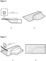
- the Figure 4 and Figure 5 show examples of different trajectories of different coating nozzles (V1-V3) of an inkjet head on an underlying concave and convex distorted surface a).
- the corresponding grid projection is shown in the respective figure b).
- the deviating alignment of the respective nozzle to the underlying surface has a direct influence on the distances that the nozzles cover on the underlying surface with constant movement of the printing unit. This results from the rigid coating head surface that cannot be adapted to the surface.
- the way the print head works is to be understood as 2-dimensional, regardless of the fact that the surface and/or the coating unit can perform a relative movement with up to 6 degrees of freedom via the actuators. This relative movement serves to advance the printing unit as parallel as possible to each surface position. Since the image data is only stored in 2-dimensional form, other data of the trajectory, such as angular deviations and differences in distance, must already be taken into account in the image data.
- the figure 6 shows an exemplary representation for obtaining the angular deviation between the normal vectors of the traversing path (vectors with the index P) and the associated normal vector of the grid area on the surface (vectors with the index S).
- collinear normal vectors there is no angular deviation between the two normal vectors.
- the normal vector of the printing plane is a multiple of the normal vector of the relevant raster area.
- the angular deviation of both normal vectors in the X and Y direction is zero in each case. If the surface is curved, the normal vectors are no longer collinear, but there are angular deviations in the X and/or Y direction ( ⁇ (x), ⁇ (y)) depending on the alignment between the workpiece surface and the traversing path.
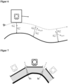
- the figure 7 shows a way of dividing bidirectionally curved surfaces into traversing and pressure paths. It is shown that the individual traversing paths overlap on the surface (S1, S2), ie that individual workpiece surface areas can in principle be coated over several traversing paths. As a function of the curvature of the surface, it can be expedient to choose different coating areas (printing paths) for each travel path. It is thus possible for the constantly curved (planar) area on the left to be coated by a printing path which corresponds to the maximum possible traversing path (large coating area per traversing path).
- the traverse path covers an area with strong curvatures (middle head)
- the figure 8 shows pressure paths as a sub-area of traversing paths on a complex workpiece surface.
- the edges of the printed webs where they meet are referred to as the cutting line.
- the so-called stitching the print paths can be placed close to each other or overlap in each case.
- the stitching makes it possible to further conceal the transitions between the print webs via the print system control so that these cut areas cannot be seen in the later decor.
- the traversing paths have different angles to the underlying surface of the cutting area.
- the figures 9 and show complex surfaces with the corresponding print paths and cutting lines.
- the corresponding surface grid and the intersection lines are also indicated on these surfaces.
- the decor of the surface to be printed is made up of the segments of the individual traversing and printing tracks. In order for these to result in a homogeneous overall picture, the image data of the individual print webs should be coordinated in such a way that they can be placed next to each other without any visible cracks in the decor.
- All adjacent print webs in which the projections of the cut lines onto the respective print web are complementary to the projection of the same cut line onto the respective adjacent print web are understood to be adjacent print webs with complementary cutting lines.
- parallel webs i.e. webs that differ only with regard to the X and Y alignment, as well as cutting lines that run constantly straight along the X axis, can be counted as "adjacent print webs with complementary cutting lines".
- adjacent print webs can be placed next to one another without additional processing of the image data.
Description
Die Erfindung betrifft ein Verfahren zum verzerrungsfreien und gleichmäßigem Beschichten von Werkstücken mit bidirektional gekrümmten Oberflächen. Im erfindungsgemäßen Verfahren wird auf Basis bereitgestellter digitaler 2D-Dekordaten und digitaler 3D-Oberflächenprofildaten eines zu beschichtenden Werkstücks die Werkstückoberfläche in Rasterflächen aufgeteilt; die Werkstückoberfläche in eine oder mehrere Verfahrbahnen eines Beschichtungskopfes aufgeteilt; die Rasterflächen entlang des Normalenvektors der Verfahrbahn an die Druckkopf-Verfahrbahn projiziert; die 2D-Dekor-Druckdaten des Dekors für jede Rasterfläche als Funktion der Ergebnisse der Rasterprojektion angepasst und die Werkstückoberfläche auf Basis der angepassten Druckdaten beschichtet. Des Weiteren betrifft die vorliegende Erfindung ein System zur Durchführung des erfindungsgemäßen Verfahrens.The invention relates to a method for the distortion-free and uniform coating of workpieces with bidirectionally curved surfaces. In the method according to the invention, the workpiece surface is divided into grid areas on the basis of provided digital 2D decorative data and digital 3D surface profile data of a workpiece to be coated; the workpiece surface is divided into one or more traverse paths of a coating head; projects the raster areas onto the printhead trajectory along the trajectory normal vector; the 2D decor print data of the decor is adjusted for each grid area as a function of the results of the grid projection and the workpiece surface is coated on the basis of the adjusted print data. Furthermore, the present invention relates to a system for carrying out the method according to the invention.
Das Aufbringen ästhetischer Dekore oder funktionaler Beschichtungen auf Oberflächen über Druckverfahren gehört seit langem zum Stand der Technik. So können beispielsweise mittels digitaler Beschichtungsverfahren wie dem Laser- oder Inkjet-Verfahren Oberflächen, beispielsweise Papier, mit individuellen Motiven oder weiteren Funktionen und Eigenschaften versehen werden. Das fundamentale Prinzip ist dabei gleich und beinhaltet eine Relativbewegung zwischen einem Druck-/Beschichtungskopf und der zu beschichteten Oberfläche. Letztere kann dann wahlweise direkt (Inkjet) oder indirekt (Laser), d.h. über einen Umweg über eine Trommel, beschichtet werden. Der Beschichtungsvorgang gestaltet sich in den Fällen als einfach, in welchen bedingt durch eine zweidimensionale Oberflächengeometrie des Produktes ein festes Verhältnis zwischen Druckkopf und Oberfläche eingehalten werden kann.The application of aesthetic decors or functional coatings to surfaces using printing processes has long been part of the state of the art. For example, digital coating processes such as laser or inkjet processes can be used to provide surfaces such as paper with individual motifs or other functions and properties. The fundamental principle is the same and involves relative movement between a print/coating head and the surface to be coated. The latter can then be coated either directly (inkjet) or indirectly (laser), ie via a detour via a drum. The coating process turns out to be simple in the cases in due to the two-dimensional surface geometry of the product, a fixed ratio between the print head and the surface can be maintained.
Im Falle komplexerer Oberflächen, beispielsweise 3-dimensionaler Oberflächen mit Sprüngen in der Oberflächenhöhe und/oder partiell in einer oder zwei Richtungen gekrümmter Oberflächen, ist das Bedrucken oder Beschichten deutlich schwieriger, da den veränderlichen Relationen zwischen Oberfläche und Druckkopf Rechnung getragen werden muss. Werden diese Oberflächen mit den üblichen Standardverfahren beschichtet, so ergeben sich als Funktion der Oberflächenabweichungen Verzerrungen oder Farbunterschiede des aufgebrachten Dekors oder aber Einbußen in der Funktionalität durch ungleichmäßig beschichtete Bereiche.In the case of more complex surfaces, e.g. 3-dimensional surfaces with jumps in surface height and/or surfaces partially curved in one or two directions, printing or coating is much more difficult, since the changing relations between surface and print head have to be taken into account. If these surfaces are coated with the usual standard methods, then, as a function of the surface deviations, there are distortions or color differences in the applied decoration or losses in functionality due to unevenly coated areas.
Eine mögliche Lösung für Massenprodukte mit "konstanter" aber nicht planarer Oberflächengeometrie, wie beispielsweise einfach gekrümmte Kaffeetassen mit konstantem Radius, besteht darin, dass über die Adaption des Druckkopfes an die spezifische Oberflächengeometrie des Produktes relativ einfach ein gleichmäßiger Beschichtungsprozess gewährleistet werden kann. Handelt es sich aber um Oberflächen mit komplexen und über die gesamte zu beschichtende Oberfläche variierenden Abweichungen in der Höhe und/oder der Krümmung, insbesondere bei partiell doppelt gekrümmten Oberflächenbereichen, so kann insbesondere für Kleinserien unter vertretbaren technischem Aufwand über die Adaption der Druckkopfgeometrie keine geeignete Anpassung mehr erreicht werden.A possible solution for mass-produced products with "constant" but non-planar surface geometry, such as simply curved coffee cups with a constant radius, is that a uniform coating process can be ensured relatively easily by adapting the print head to the specific surface geometry of the product. However, in the case of surfaces with complex deviations in height and/or curvature that vary over the entire surface to be coated, in particular in the case of partially double-curved surface areas, no suitable adjustment can be made by adapting the print head geometry with reasonable technical effort, especially for small series more can be achieved.
Auch in der Patentliteratur finden sich die unterschiedlichsten Ansätze zur Bedruckung oder Beschichtung von gekrümmten Oberflächen.A wide variety of approaches to printing or coating curved surfaces can also be found in the patent literature.
So offenbart beispielsweise die
Die
In einem weiteren Patentdokument, der
Weitere Verfahren zur Korrektur von Druckdaten für 3D-Oberflächen werden beispielsweise in der
Trotz der schon bekannten Lösungen zum Beschichten 3-dimensionaler Oberflächen besteht weiterhin Bedarf an technischen Lösungen, welche in der Lage sind, unterschiedlichste Oberflächengeometrien, und insbesondere komplexe Oberflächengeometrien mit Krümmungen in mehr als einer Oberflächenrichtung, verzerrungsfrei, flexibel und mit einem deutlichen Zuwachs in der Verarbeitungsgeschwindigkeit zu beschichten.Despite the already known solutions for coating 3-dimensional surfaces, there is still a need for technical solutions that are able to coat a wide variety of surface geometries, and in particular complex surface geometries with curvatures in more than one surface direction, distortion-free, flexible and with a significant increase in processing speed.
Es ist die Aufgabe der vorliegenden Erfindung ein Verfahren bereitzustellen, welches ermöglicht, Dekore und Beschichtungen an komplexe 3-dimensionale Oberflächen zu adaptieren und diese verzerrungsfrei auf die Oberflächen aufzubringen. Es ist weiterhin die Aufgabe der vorliegenden Erfindung ein System für das erfindungsgemäße Verfahren bereitzustellen.It is the object of the present invention to provide a method which makes it possible to adapt decors and coatings to complex 3-dimensional surfaces and to apply them to the surfaces without distortion. It is also the object of the present invention to provide a system for the method according to the invention.
Gelöst wird die Aufgabe für das Verfahren durch die Merkmale des Anspruchs 1 und für das System durch die Merkmale des Anspruchs 14. Bevorzugte Ausführungsformen des Verfahrens und des Systems sind in den Unteransprüchen angegeben.The task is solved for the method by the features of claim 1 and for the system by the features of claim 14. Preferred embodiments of the method and the system are specified in the dependent claims.
Erfindungsgemäß ist ein Verfahren zum verzerrungsfreien Beschichten 3-dimensionaler Werkstücke mit partiell bidirektional gekrümmten Oberflächen, wobei das Verfahren mindestens die Schritte umfasst:
- a) Bereitstellung digitaler 2D-Daten eines aufzubringenden Dekors und digitaler 3D-Oberflächenprofildaten eines zu beschichtenden Werkstücks;
- b) Aufteilen der Werkstückoberfläche in Flächen eines Rasters, wobei die einzelnen Flächen des Rasters aus einem Linienzug äquidistanter Linien mit Abstand X0 parallel zu einer X- und einem weiteren, dazu orthogonalen Linienzug äquidistanter Linien mit Abstand Y0 parallel zur einer Y-Richtung ausgebildet werden;
- c) Aufteilen der Werkstückoberfläche in eine oder mehrere Verfahrbahnen eines Beschichtungskopfes, wobei die Verfahrbahnen oberhalb der Werkstückoberfläche verlaufen und die Schnittlinien benachbarter Verfahrbahnen zumindest aneinanderstoßen;
- d) Projektion der die Rasterflächen begrenzenden Linienzüge an eine oder mehrere Verfahrbahnen oberhalb der betreffenden Rasterfläche, wobei die Projektion entlang des Normalenvektors der jeweiligen Verfahrbahn erfolgt;
- e) Anpassen der 2D-Dekor-Druckdaten für jede Rasterfläche, wobei die Anpassung der Druckdaten der Rasterfläche sowohl eine Funktion der ursprünglich bereitgestellten 2D-Daten des Dekors als auch eine Funktion der Rasterprojektion an die Verfahrbahn ist; und
- f) Beschichten der Werkstückoberfläche auf Basis der angepassten Dekor-Druckdaten.
- a) Provision of digital 2D data of a decoration to be applied and digital 3D surface profile data of a workpiece to be coated;
- b) Dividing the workpiece surface into areas of a grid, the individual areas of the grid being formed from a polyline of equidistant lines at a distance X 0 parallel to an X direction and a further polyline of equidistant lines orthogonal thereto at a distance Y 0 parallel to a Y direction become;
- c) dividing the workpiece surface into one or more traversing paths of a coating head, the traversing paths running above the workpiece surface and the intersection lines of adjacent traversing paths at least abut one another;
- d) projection of the polylines delimiting the grid areas onto one or more travel paths above the relevant grid surface, the projection taking place along the normal vector of the respective travel path;
- e) Adaptation of the 2D decorative print data for each raster area, wherein the adaptation of the print data of the raster area is both a function of the originally provided 2D data of the decoration and a function of the raster projection to the trajectory; and
- f) Coating of the workpiece surface based on the adjusted decor print data.
Überraschenderweise hat sich gezeigt, dass man über das erfindungsgemäße Verfahren in der Lage ist, selbst sehr unregelmäßig und stark gekrümmte 3D Oberflächen reproduzierbar, schichtdickenabweichungsfrei und verzerrungsfrei zu beschichten. Neben der oberflächenangepassten Qualität des Beschichtungsergebnisses durch die rasterprojektionsangepasste Beschichtungsdichte ergeben sich zudem deutliche Vorteile in den Beschichtungsgeschwindigkeiten, da durch die vorgeschlagene geometrisch bedingte Anpassung deutlich weniger Verfahrbahnen des Druckkopfes pro Oberflächeneinheit eingeplant werden müssen. Es können innerhalb einer Verfahrbahn auch ungünstige Winkelrandbereiche mit erfasst und beschichtet werden. Der effektive Druckbereich einer Verfahrbahn wird also bei gleichbleibender Beschichtungsqualität erhöht, da den Verzerrungen in den Bereichen "ungünstiger" Oberflächengeometrien durch die Anpassung entgegengewirkt wird. In Konsequenz führt dies dazu, dass die effektive Beschichtungsfläche über eine Verfahrbahn gesteigert werden kann, sodass der Beschichtungskopf zur vollständigen Beschichtung der Oberfläche eine geringere Strecke zurücklegen muss. Diese positiven Effekte können die Ökonomie von Beschichtungsprozessen teils bidirektional gekrümmter Oberflächen deutlich steigern.Surprisingly, it has been shown that the method according to the invention is capable of coating even very irregular and strongly curved 3D surfaces in a reproducible manner, without layer thickness deviations and without distortion. In addition to the surface-adapted quality of the coating result due to the grid projection-adapted coating density, there are also clear advantages in the coating speeds, since the proposed geometrically-related adjustment means that significantly fewer traverse paths of the print head per surface unit have to be planned. Unfavorable angular edge areas can also be recorded and coated within a traversing path. The effective pressure range of a traversing path is thus increased while the coating quality remains the same, since the adjustment counteracts the distortions in the areas of "unfavorable" surface geometries. As a consequence, the effective coating area can be increased over a traversing path, so that the coating head has to travel a shorter distance to completely coat the surface. These positive effects can significantly increase the economy of coating processes, some of which are bidirectionally curved surfaces.
Über das erfindungsgemäße Verfahren wird ein verzerrungsfreies Beschichten ermöglicht. Durch gekrümmte, und insbesondere durch in mehr als eine Richtung gekrümmte, Oberflächen kommt es aufgrund der abweichenden Ausrichtung der jeweiligen Düsen eines Beschichtungskopfes zur darunterliegenden Oberfläche und basierend auf den unterschiedlichen pro Zeiteinheit zurückgelegten Oberflächenabschnitten (siehe
Mittels des erfindungsgemäßen Verfahren können 3-dimensionale Werkstücke beschichtet werden. 3D-Werkstücke sind Werkstücke welche, zumindest abschnittweise, eine nicht planare Oberfläche aufweisen. Die Werkstückoberfläche weist also Höhenunterschiede und Unterschiede in der Steigung der Oberfläche auf. Bedingt durch die Höhenunterschiede und aufgrund der Steigung der Oberfläche ist die Oberfläche des Werkstücks gekrümmt.3-dimensional workpieces can be coated using the method according to the invention. 3D workpieces are workpieces which, at least in sections, have a non-planar surface. The workpiece surface therefore has differences in height and differences in the slope of the surface. Due to the differences in height and the slope of the surface, the surface of the workpiece is curved.
Die Werkstücke können partiell bidirektional gekrümmten Oberflächen aufweisen. Eine Oberfläche ist im Sinne der Erfindung bidirektional gekrümmt, wenn ein Teil der Oberfläche eine Krümmung im mathematischen Sinn in zumindest zwei unterschiedliche Richtungen aufweist. Beispiele für solche Oberflächengeometrien sind in den Figuren angegeben.The workpieces can partially have bidirectionally curved surfaces. A surface is bidirectionally curved within the meaning of the invention if part of the surface has a curvature in the mathematical sense in at least two different directions. Examples of such surface geometries are given in the figures.
Im Schritt a) werden digitale 2D-Daten eines aufzubringenden Dekors und digitale 3D-Oberflächenprofildaten eines zu beschichtenden Werkstücks bereitgestellt. Im ersten Schritt werden Daten für die vorliegende Beschichtungssituation bereitgestellt. Die Daten können dabei vor Ort erhoben oder beispielsweise durch eine Datenbank bereitgestellt werden. Die Erhebung der Oberflächenprofildaten kann beispielsweise durch einen Scanvorgang, beispielsweise über ein Laserscannen erfolgen. Die Oberflächenprofildaten enthalten dabei mindestens das Oberflächenprofil des Werkstücks, beispielsweise als XYZ-Matrix, mit X, Y, Z als Ortskoordinaten.In step a), digital 2D data of a decoration to be applied and digital 3D surface profile data of a workpiece to be coated are provided. In the first step, data for the existing coating situation is provided. The data can be collected on site or made available, for example, by a database. The surface profile data can be collected, for example, by a scanning process, for example by laser scanning. The surface profile data contain at least the surface profile of the workpiece, for example as an XYZ matrix, with X, Y, Z as location coordinates.
Das Dekor kann beispielsweise ein komplexes Bild, eine geometrische Figur oder eine oder mehrere Linien darstellen. Das Dekor wird dabei auf mindestens einen Teil der Oberfläche des Werkstücks aufgebracht werden. Das Dekor umfasst dabei nicht nur das Bereitstellen optischer Bilddaten. Von dem Begriff Dekor sind auch funktionale Beschichtungen umfasst, welche auf die Werkstückoberfläche aufgebracht werden. Das Dekor umfasst in diesen Fällen dann nicht nur einen Bildeindruck, sondern kann weitere funktionale Eigenschaften, wie beispielsweise Schalter, Leuchtflächen oder haptische Eigenschaften bereitstellen. Die Dekordaten umfassen dabei mindestens sowohl die Positions- wie auch die aufzubringende Volumenmenge an den Positionsdaten. Insofern werden unter dem Dekor optische wie auch funktionale Schichtbereiche auf der Werkoberfläche verstanden.For example, the decor may represent a complex image, a geometric figure, or one or more lines. In this case, the decoration is applied to at least part of the surface of the workpiece. The decor not only includes the provision of optical image data. The term decor also includes functional coatings that are applied to the workpiece surface. In these cases, the decor not only includes a visual impression, but can also provide other functional properties, such as switches, luminous surfaces or haptic properties. In this case, the decorative data include at least both the position and the volume quantity to be applied to the position data. In this respect, the decoration is understood to mean optical as well as functional layered areas on the surface of the work.
Im Schritt b) wird die Werkstückoberfläche in Flächen eines Rasters aufgeteilt, wobei die einzelnen Flächen des Rasters aus einem Linienzug äquidistanter Linien mit Abstand X0 parallel zu einer X- und einem weiteren, dazu orthogonalen Linienzug äquidistanter Linien mit Abstand Y0 parallel zur einer Y-Richtung ausgebildet werden. Die Werkstückoberfläche wird also in quadratische oder rechteckige Raster aufgeteilt, wobei das Rastermaß für beide Richtungen gleich oder unterschiedlich sein kann. Das Rastermaß, also der Abstand zweier benachbarter Linien desselben Zuges, kann dabei beispielsweise 1 mm bis 10 cm betragen. Das Maß kann dabei als Funktion der auftretenden Oberflächengeometrie des Werkstücks und insgesamt als Funktion dessen räumlicher Abmessungen gewählt werden. Werkstücke mit 3D-Oberflächenabweichungen auf kleinen Längenskalen können bevorzugt ein kleines Rastermaß erfordern. Liegen die 3D-Eigenschaften des Werkstücks auf größeren Längenskalen, so kann eine größere Rasterung angebracht sein. Die Festlegung des XY-Koordinatensystems kann als Funktion der Oberflächensymmetrie des Werkstücks gewählt werden. Ein Linienzug besteht dabei aus mindestens zwei parallel verlaufenden Linien.In step b), the workpiece surface is divided into areas of a grid, with the individual areas of the grid consisting of a polyline of equidistant lines at a distance X 0 parallel to an X and a further polyline, orthogonal thereto, of equidistant lines at a distance Y 0 parallel to a Y -direction to be trained. The workpiece surface is thus divided into square or rectangular grids, with the grid dimension being the same or different for both directions. The grid dimension, ie the distance between two adjacent lines of the same train, can be 1 mm to 10 cm, for example. The measure can be selected as a function of the occurring surface geometry of the workpiece and overall as a function of its spatial dimensions. Workpieces with 3D surface deviations on small length scales may preferably require a small grid dimension. If the 3D properties of the workpiece are on larger length scales, a larger grid may be appropriate. The definition of the XY coordinate system can be chosen as a function of the surface symmetry of the workpiece. A polyline consists of at least two parallel lines.
Im Schritt c) erfolgt das Aufteilen der Werkstückoberfläche in eine oder mehrere Verfahrbahnen eines Beschichtungskopfes, wobei die Verfahrbahnen oberhalb der Werkstückoberfläche verlaufen und die Schnittlinien benachbarter Verfahrbahnen zumindest aneinanderstoßen. Innerhalb dieses Schrittes wird die gesamte Werkstückoberfläche in Verfahrbahnen eines Beschichtungskopfes aufgeteilt, wobei jedes Oberflächenelement, welches beschichtet werden soll, zumindest einmal überfahren wird. Der Abstand der Verfahrbahn zum Werkstück kann, muss aber nicht, konstant gewählt werden. Abstände zwischen Beschichtungskopf und Werkstückoberfläche zwischen 2,5 mm und 5 cm haben sich als geeignet erwiesen. Die Schnittlinie einer Verfahrbahn ist dabei die Randlinie der Verfahrbahn und kennzeichnet die Außenlinie des maximal beschichtbaren Bereichs des Beschichtungskopfes auf dieser Bahn. Diese Schnittlinien stoßen auf unterschiedlichen Verfahrbahnen aneinander, wenn der Abstand der Schnittlinien zweier benachbarter Verfahrbahnen kleiner oder gleich der Beschichtungsauflösung ist. Es ist aber auch möglich, dass die einzelnen Verfahrbahnen so festgelegt werden, dass diese an den Randbereichen, also an den Schnittlinien, überlappen. Mögliche Überlappungsbereiche benachbarter Verfahrbahnen können beispielsweise 5 - 25% der gesamten Beschichtungskopffläche betragen. Bei einer Überlappung der Verfahrbahn können also bestimmte Oberflächenbereiche von mindestens zwei Verfahrbahnen beschichtet werden.In step c), the workpiece surface is divided into one or more traversing paths of a coating head, with the traversing paths being above the workpiece surface run and the intersection lines of adjacent traversing paths at least abut one another. Within this step, the entire workpiece surface is divided into traversing paths of a coating head, with each surface element that is to be coated being passed over at least once. The distance between the traversing path and the workpiece can, but does not have to, be constant. Distances between the coating head and the workpiece surface of between 2.5 mm and 5 cm have proven to be suitable. The line of intersection of a traversing path is the edge line of the traversing path and characterizes the outer line of the maximum coatable area of the coating head on this path. These intersection lines meet on different traverse paths if the distance between the intersection lines of two adjacent traverse paths is less than or equal to the coating resolution. However, it is also possible for the individual traversing paths to be defined in such a way that they overlap at the edge areas, ie at the cutting lines. Possible overlapping areas of adjacent traversing paths can amount to, for example, 5-25% of the total coating head area. If the traversing path overlaps, certain surface areas of at least two traversing paths can be coated.
Im Schritt d) erfolgt die Projektion der die Rasterflächen begrenzenden Linienzüge an eine oder mehrere Verfahrbahnen oberhalb der betreffenden Rasterfläche, wobei die Projektion entlang des Normalenvektors der jeweiligen Verfahrbahn erfolgt. Dieses Raster wird entlang der Normalenvektoren der jeweils über dem Oberflächenabschnitt liegenden einen oder mehreren Verfahrbahnen projiziert. An den Schnittlinien und den Übergangsbereichen der Verfahrbahnen bedeutet dies, dass eine Projektion an ggf. zwei betroffene Verfahrbahnen durchgeführt werden kann, wobei sich die Projektionen der Raster in diesem Bereich aufgrund der unterschiedlichen Ausrichtungswinkel der jeweiligen Verfahrbahnen unterscheiden können. Die Vektorebenen der Verfahrbahnen mit den projizierten Rasterlinien und Schnittlinien werden anschließend in eine 2-dimensionale Form transformiert. Die 2-dimensionalen Verfahrbahnen werden entsprechend ihrer Positionen nebeneinander positioniert, so dass jeweils die Schnittlinien der benachbarten Verfahrbahnen nebeneinanderliegen. Lassen sich aufgrund ungünstiger Winkelbereiche in den Außenbereichen der Verfahrbahn bestimmte Werkstückoberflächenbereiche nicht adäquat innerhalb bestimmter Winkelabweichungen zum Beschichtungskopf beschichten, so kann die Verfahrbahn auf eine Druckbahn reduziert werden. Die Druckbahn weist dieselbe Ausrichtung aber einen kleineren Flächenbereich verglichen zur Verfahrbahn auf, wobei die Düsen an den Rändern der Verfahrbahn dann nicht mehr zur Beschichtung genutzt werden. Anschließend werden die Schnittlinien der jeweils benachbarten Druckbahnen dahingehend bewertet, ob diese zu einander komplementär sind, das heißt sich lückenlos ergänzen. Lassen sich die Schnittlinien benachbarten Druckbahnen durchgängig aneinander anfügen, so ist keine Harmonisierung der Bilddaten der Druckbahnen erforderlich. Diese Druckbahnen können direkt nebeneinander ausgerichtet über den 2-dimensionalen Bilddaten positioniert werden.In step d), the lines delimiting the grid areas are projected onto one or more travel paths above the relevant grid surface, the projection taking place along the normal vector of the respective travel path. This raster is projected along the normal vectors of the one or more traversing paths lying above the surface section. At the intersection lines and the transition areas of the travel paths, this means that a projection can be carried out on two affected travel paths, where the projections of the grids in this area can differ due to the different orientation angles of the respective travel paths. The vector planes of the traversing paths with the projected grid lines and cutting lines are then transformed into a 2-dimensional form. The 2-dimensional traversing paths are positioned next to each other according to their positions, so that the intersection lines of the adjacent traversing paths are next to each other. Can be due to unfavorable angle ranges If certain workpiece surface areas in the outer areas of the traversing path are not adequately coated within certain angular deviations from the coating head, the traversing path can be reduced to a printing path. The print path has the same orientation but a smaller surface area compared to the traverse path, with the nozzles at the edges of the traverse path then no longer being used for coating. Then the intersection lines of the respective adjacent print webs are evaluated to determine whether they are complementary to one another, i.e. complement each other without gaps. If the cutting lines of adjacent print webs can be continuously attached to one another, no harmonization of the image data of the print webs is required. These print webs can be positioned directly next to each other over the 2-dimensional image data.
Im Schritt e) erfolgt eine Anpassung der 2D-Dekor-Druckdaten für jede Rasterfläche, wobei die Anpassung der Druckdaten der Rasterfläche sowohl eine Funktion der ursprünglich bereitgestellten 2D-Daten des Dekors als auch eine Funktion der Rasterprojektion an die Verfahrbahn ist. Das durch einen jeweiligen Bereich des Druckkopf aufzubringende Volumen ergibt sich also als Funktion aus der jeweiligen Abweichung der Druckkopfausrichtung von der Oberfläche sowie dem vorgesehenen Schichtvolumen innerhalb des jeweiligen Rastersbereiches. Die Anpassung der Daten einer Rasterfläche ist demzufolge einmal davon abhängig, ob das Dekor überhaupt einen Pixel an dieser Oberflächenstelle vorsieht. Falls das Dekor an dieser Stelle eine Beschichtung vorsieht, dann wird die Pixeldichte zudem als Funktion der Oberflächengeometrie an dieser Oberflächenstelle, proportional transformiert über die Projektion an die Verfahrbahn, korrigiert. Bei parallel verlaufenden Flächen, das heißt die Normalenvektoren der Vektorebene der Verfahrbahn und des jeweiligen Schnittpunktes der Oberflächen sind parallel, sind die Abstände der Projektionen der Rasterlinien gleich zu denen der Rasterlinien auf der Oberfläche. Bei nicht parallelen Verläufen ergeben sich abweichende Abstände, wobei die Abstände der projizierten Rasterlinien nur kleiner/gleich den Abständen auf der Oberfläche sein können. Dieser Effekt ergibt sich daraus, dass mit zunehmender Winkelabweichung die auf der Oberfläche zu bedruckende Strecke steigt. Die Winkelabweichung entspricht dabei der durch die Projektion vernachlässigten Höhenveränderung, durch die die Rasterlinien in der 2dimensionalen Projektion bei konstantem Abstand auf der Oberfläche scheinbar näher zusammenrücken. Die Bilddaten werden nun so aufbereitet werden, dass entsprechend der Verringerung des Abstandes der Rasterlinien sowohl in Längs- als auch in Breitenausrichtung die Anzahl der Druckpunkte erhöht wird. Ergebnis dieser Auflösungsanpassung ist, dass zwischen den Rasterlinien auf der Werkstückoberfläche stets dieselbe Zahl an Druckpunkten in Längs- als auch Breitenausrichtung vorhanden ist. Dies kann eine gleichmäßige Beschichtung sicherstellen, welche besonders verzerrungsfreie Bilder und/oder robuste funktionale Bereiche bereitstellt. Die 2D-Dekor-Druckdaten für jede Rasterfläche umfassen dabei mindestens die Anzahl der im Raster aufzubringenden Punkte (Pixel) sowie die Auftragsmenge pro Pixel.In step e), the 2D decor print data for each grid area is adjusted, with the adjustment of the print data of the grid area being both a function of the originally provided 2D data of the decor and a function of the grid projection to the traversing path. The volume to be applied by a respective area of the print head thus results as a function of the respective deviation of the print head alignment from the surface and the intended layer volume within the respective raster area. The adaptation of the data of a raster area is therefore dependent on whether the decor even provides a pixel at this surface location. If the decor provides a coating at this point, then the pixel density is also corrected as a function of the surface geometry at this surface point, proportionally transformed via the projection onto the traversing path. In the case of parallel surfaces, i.e. the normal vectors of the vector plane of the traversing path and the respective intersection of the surfaces are parallel, the distances between the projections of the grid lines and those of the grid lines on the surface are the same. In the case of non-parallel courses, deviating distances result, whereby the distances between the projected grid lines can only be less than or equal to the distances on the surface. This effect results from the fact that the distance to be printed on the surface increases with increasing angular deviation. The angular deviation corresponds to that by the Projection neglected elevation change, which makes the grid lines appear closer together in the 2-dimensional projection at a constant distance on the surface. The image data will now be processed in such a way that the number of printing dots is increased in accordance with the reduction in the distance between the grid lines, both in the longitudinal and in the width direction. The result of this resolution adjustment is that between the grid lines on the workpiece surface there is always the same number of print dots in lengthwise and widthwise direction. This can ensure an even coating that provides particularly distortion-free images and/or robust functional areas. The 2D decorative print data for each grid area includes at least the number of dots (pixels) to be applied in the grid and the application quantity per pixel.
Im letzten Schritt f) wird die Werkstückoberfläche auf Basis der angepassten Dekor-Druckdaten beschichtet. Die Beschichtung erfolgt dabei in der Regel durch das Aufbringen von Flüssigkeiten auf die Werkstückoberfläche. Bei den Flüssigkeiten kann es sich beispielsweise um Farben, Oberflächenversiegelungssubstanzen oder um andere funktionale Verbindungen handeln, welche der Oberfläche ein anderes ästhetisches oder funktionales Erscheinungsbild verleihen. Die Beschichtung kann beispielsweise mittels eines Inkjet-Verfahrens erfolgen. Mittels der Beschichtung lassen sich Funktionsschichten herstellen, wobei Funktionsschichten zumindest partiell zusammenhängende Bereiche sind, welche auf die Werkstückoberfläche aufgebracht oder aufgedruckt werden. Diese zusammenhängenden Bereiche erfüllen dabei weitergehende funktionale Eigenschaften auf der Werkstückoberfläche. Diese funktionalen Eigenschaften können beispielsweise haptischer oder optischer Art sein. Denkbar sind leuchtende Bereiche oder das Aufbringen von Dekoren. Es sind aber auch funktionale Bereiche oder Schichten denkbar, welche festgelegt elektrische Eigenschaften in Form von Schaltern aufweisen. Des Weiteren können funktionale Schichten auch weitere optische Eigenschaften in Form von leuchtenden Bereichen bereitstellen. Zusätzlich können über die funktionalen Bereiche auch weitere haptische Eigenschaften, wie beispielsweise ein tastbares Relief darstellen.In the last step f), the workpiece surface is coated on the basis of the adapted decor print data. The coating is usually done by applying liquids to the workpiece surface. The liquids can be, for example, paints, surface sealing substances or other functional compounds that give the surface a different aesthetic or functional appearance. The coating can take place, for example, by means of an inkjet process. Functional layers can be produced by means of the coating, with functional layers being at least partially contiguous areas which are applied or printed onto the workpiece surface. These connected areas fulfill further functional properties on the workpiece surface. These functional properties can be of a haptic or visual nature, for example. Luminous areas or the application of decorations are conceivable. However, functional areas or layers are also conceivable which have specified electrical properties in the form of switches. Furthermore, functional layers can also provide other optical properties in the form of luminous areas. In addition, other haptic properties, such as a tactile relief, can also be displayed via the functional areas.
In einer bevorzugten Ausgestaltung des Verfahrens kann das Anpassen der 2D-Dekor-Druckdaten im Verfahrensschritt e) die Pixeldichte der Rasterflächen umfassen. Das Anpassen der Pixeldichte hat sich für das vorliegende Verfahren als besonders geeignet erwiesen, wobei insbesondere in den bidirektional gekrümmten Bereichen die Anzahl an Bildpunkten, d.h. die Pixeldichte, angepasst wird. Dies kann zu besonders verzerrungsfreien Beschichtungen auch auf schwierig zu bedruckenden Geometrien beitragen.In a preferred embodiment of the method, the adjustment of the 2D decorative print data in method step e) can include the pixel density of the raster areas. Adjusting the pixel density has proven to be particularly suitable for the present method, with the number of pixels, i.e. the pixel density, being adjusted in particular in the bidirectionally curved areas. This can contribute to particularly distortion-free coatings, even on geometries that are difficult to print on.
In einer bevorzugten Ausgestaltung des Verfahrens kann das Anpassen der 2D-Dekor-Druckdaten im Verfahrensschritt e) die Auftragsmenge auf die jeweilige Rasterfläche umfassen. Das Anpassen der Volumenmenge pro Rasterfläche hat sich für das vorliegende Verfahren als besonders geeignet erwiesen, wobei insbesondere in den bidirektional gekrümmten Bereichen das Auftragsvolumen der einzelnen Pixel und somit auch das Auftragsvolumen pro Rasterflächen umfassend ein oder mehrere Pixel angepasst wird. Dies kann zu besonders verzerrungsfreien Beschichtungen auch auf schwierig zu bedruckenden Geometrien beitragen.In a preferred embodiment of the method, the adjustment of the 2D decorative print data in method step e) can include the quantity applied to the respective grid area. Adjusting the volume per grid area has proven to be particularly suitable for the present method, with the application volume of the individual pixels and thus also the application volume per grid area being adjusted to include one or more pixels in the bidirectionally curved areas in particular. This can contribute to particularly distortion-free coatings, even on geometries that are difficult to print on.
In einer bevorzugten Ausgestaltung des Verfahrens kann in einem weiteren Schritt der Normalenvektor für jede Rasterfläche aus Schritt b) ermittelt werden. Durch die Rasterlinien wird die Oberfläche in Quadrate oder Rechtecke eingeteilt, wobei ein Oberflächenabschnitt (Raster) durch 4 Rasterlinien begrenzt ist. Bei verzerrten Oberflächenbereichen werden die Quadrate oder Rechtecke aufgrund der Krümmungen in 2 Richtungen selber verzerrt. Bei gleichbleibenden Abständen der Rasterlinien führen unterschiedliche Krümmungen der Teilbereiche zu Krümmungen in den Rasterlinien, woraus die Verzerrung der Flächen resultiert. Für diesen Oberflächenbereich lässt sich ein Normalenvektor festlegen welcher senkrecht auf der durch die Rasterlinien begrenzten Teiloberfläche steht. Ist innerhalb der Rasterfläche die Oberfläche selbst noch gekrümmt, kann der Normalenvektor beispielsweise für die planare Fläche angegeben werden, welche die gekrümmte Oberfläche im Raster schneidet und oberhalb und unterhalb der Schnittlinie zur gekrümmten Werkstückoberfläche im Raster denselben Rauminhalt aufweist.In a preferred embodiment of the method, the normal vector for each grid area from step b) can be determined in a further step. The grid lines divide the surface into squares or rectangles, with a surface section (grid) being delimited by 4 grid lines. In the case of distorted surface areas, the squares or rectangles themselves are distorted in 2 directions due to the curvature. If the distances between the grid lines remain the same, different curvatures of the partial areas lead to curvatures in the grid lines, which results in the distortion of the surfaces. A normal vector can be defined for this surface area, which is perpendicular to the partial surface delimited by the grid lines. If the surface itself is still curved within the grid area, the normal vector can be specified for the planar surface, for example, which intersects the curved surface in the grid and has the same volume above and below the line of intersection to the curved workpiece surface in the grid.
In einer bevorzugten Ausführungsform des Verfahrens kann die projektionsabhängige Dichteanpassung in Schritt e) entweder als Funktion e1) der Winkelabweichungen α(x,y) des Normalenvektors der Rasterfläche in der X- (α(x)) wie auch in der Y-Richtung (α(y)) zum Normalenvektor der Verfahrbahn; oder e2) der mittleren Abstände der Rasterlinien in X- (ΔX), in Y-Richtung (ΔY) oder als Kombination der mittleren Abstände in XY-Richtung (ΔXY) der auf die Verfahrbahn projizierten Rasterlinien erfolgen. Zur Anpassung der Pixeldichte haben sich die Winkelabweichungen zwischen Normalenvektor der betreffenden Rasterfläche und der Verfahrbahn als besonders geeignet erwiesen. Die prinzipiellen Größen und Relationen zwischen den beiden Normalenvektoren sind dabei weiter hinten in den Figuren dargestellt und diskutiert. Diese Parameter, d.h. die Winkel zwischen beiden Vektoren, lassen sich einfach und reproduzierbar bestimmen und Anpassungen über diese Differenzen führen zu "harmonischen" Pixel-Dichteverläufen. Ebenso harmonische Anpassungen können sich über die Berücksichtigung der "Rasterweite" in der X und der Y-Richtung ergeben. Die Differenz dieser Projektion ist ein Maß für die Abweichung der vorliegenden zu einer planaren Oberflächengeometrie. Falls sich für ein Raster, bedingt über die Oberflächeneigenschaften des Werkstücks, verschiedene Rasterabstände ergeben, wird der mittlere Linienabstand zur Korrektur herangezogen.In a preferred embodiment of the method, the projection-dependent density adjustment in step e) can be carried out either as a function e1) of the angular deviations α(x,y) of the normal vector of the screen area in the X (α(x)) and in the Y direction (α (y)) to the normal vector of the trajectory; or e2) the average spacing of the grid lines in the X (ΔX), in the Y direction (ΔY) or as a combination of the average spacing in the XY direction (ΔXY) of the grid lines projected onto the traversing path. The angular deviations between the normal vector of the grid area in question and the traversing path have proven to be particularly suitable for adjusting the pixel density. The basic sizes and relationships between the two normal vectors are shown and discussed later in the figures. These parameters, i.e. the angles between the two vectors, can be determined easily and reproducibly, and adjustments based on these differences lead to "harmonious" pixel density gradients. Equally harmonious adjustments can result from considering the "grid width" in the X and Y directions. The difference in this projection is a measure of the deviation of the present surface geometry from a planar one. If there are different grid spacings for a grid due to the surface properties of the workpiece, the average line spacing is used for correction.
In einer weiteren Ausgestaltung des Verfahrens kann die Aufteilung der Werkstückoberfläche in mehrere Verfahrbahnen in Schritt c) sequentiell erfolgt, wobei in einem ersten Schritt eine erste Verfahrbahn D0 und in weiteren Schritten die folgenden Verfahrbahnen jeweils benachbart zur vorhergehenden Verfahrbahn festgelegt werden, wobei die weiteren Verfahrbahnen entweder lückenlos an benachbarte Verfahrbahn anschließen oder überlappend zu diesen festgelegt werden. Die Aufteilung der Werkstückoberfläche in Verfahrbahnen kann günstigerweise so erfolgen, dass eine erste Verfahrbahn festgelegt und die weiteren Verfahrbahnen zu beiden Seiten der ersten Verfahrbahn lückenlos an diese anschließen. Es ist aber auch möglich, dass die Verfahrbahnen überlappend ausgerichtet sind, so dass ein und derselbe Werkstückoberflächenbereich von beispielsweise zwei unterschiedlichen Verfahrbahnen aus beschichtet werden kann. Die Festlegung, welche der beiden oder ob sogar beide Verfahrbahnen den überlappenden Bereich beschichten kann als Funktion der vorliegenden Winkelabweichungen oder anhand weiterer Überlegungen getroffen werden. Auf diese Art und Wiese kann die gesamte Werkstückoberfläche angepasst beschichtet werden.In a further embodiment of the method, the workpiece surface can be divided into several traversing paths in step c) sequentially, with a first traversing path D 0 being defined in a first step and the following traversing paths each being defined adjacent to the preceding traversing path in further steps, with the further traversing paths either connect seamlessly to adjacent traversing paths or be defined as overlapping with them. The subdivision of the workpiece surface into traversing paths can favorably take place in such a way that a first traversing path is defined and the further traversing paths on both sides of the first traversing path are connected to it without gaps. However, it is also possible for the traversing paths to be aligned so that they overlap, so that one and the same workpiece surface area can be coated from, for example, two different traversing paths. Determining which of the two or even both traverse paths can coat the overlapping area as a function of the existing angular deviations or based on them further considerations are made. In this way, the entire workpiece surface can be coated in an adapted manner.
In einem weiteren Aspekt des Verfahrens kann der Schritt c) die Schritte umfassen:
- c1) Festlegen eines aktiven Beschichtungsbereichs für jede Verfahrbahn als Funktion der Projektionen der Schnittlinien und der Rasterflächen an die Verfahrbahn;
- c2) Auswahl eines aktiven Beschichtungsbereiches einer Verfahrbahn D0; und
- c3) Angleichen der aktiven Beschichtungsbereiche der jeweils benachbarten Verfahrbahnen (D-1 und D+1), wobei die Angleichung derart erfolgt, dass sich aktive Beschichtungsbereiche benachbarter Verfahrbahnen lückenlos ergänzen. Als Funktion der Oberflächengeometrie des Werkstücks hat es sich als günstig erwiesen, dass nicht immer die gesamte mögliche Beschichtungsfläche eines Beschichtungskopfes auf seiner Verfahrbahn genutzt wird. Dies kann in den Fällen ungünstig sein, wenn beispielsweise die Oberfläche des Werkstücks auf der Größenskala der Verfahrbahn sehr inhomogen, d.h. stark gewölbt ist. In diesen Fällen kann es sinnvoll sein, nicht die volle Verfahrbahnbreite als Druckbahn zu nutzen und beispielsweise die Ränder der Verfahrbahn unbeschichtet zu lassen. Die Beschichtung des Oberflächenbereiches kann dann über die benachbarte Verfahrbahn erfolgen, welche eine homogenere zu beschichtende Oberfläche enthalten kann. Durch diese Aufteilung zwischen Verfahrbahn und Druckbahn kann eine homogenere Beschichtung über die Oberfläche erhalten werden.
- c1) determining an active coating area for each traverse path as a function of the projections of the intersection lines and the grid areas onto the traverse path;
- c2) selection of an active coating area of a traversing path D 0 ; and
- c3) Alignment of the active coating areas of the respectively adjacent traversing paths (D −1 and D +1 ), the aligning taking place in such a way that active coating areas of adjacent traversing paths complement one another without gaps. As a function of the surface geometry of the workpiece, it has proven advantageous that the entire possible coating surface of a coating head is not always used on its traversing path. This can be unfavorable in cases where, for example, the surface of the workpiece is very inhomogeneous on the size scale of the traversing path, ie is heavily curved. In these cases, it can make sense not to use the full traversing path width as a print path and, for example, to leave the edges of the traversing path uncoated. The surface area can then be coated via the adjacent travel path, which can contain a more homogeneous surface to be coated. This division between the traversing path and the printing path allows a more homogeneous coating to be obtained over the surface.
Innerhalb einer weiteren, bevorzugen Charakteristik des Verfahrens kann in Schritt c1) der aktive Beschichtungsbereich einer Verfahrbahn als Funktion der maximalen Winkelabweichung zwischen Verfahrbahn-Normalenvektor und Normalenvektoren der darunterliegenden Rasterflächen festgelegt werden. Unter bestimmten Oberflächengeometrien kann es vorteilhaft sein, dass die Außenbereiche der Verfahrbahn eine zu hohe Winkelabweichung verglichen mit den anderen Beschichtungsdüsen im "inneren" der Verfahrbahn aufweisen. Um diese Situation abzubilden, kann beispielsweise eine maximale Winkelabweichung zwischen den Normalenvektoren von beispielsweise maximal 25°, bevorzugt maximal 20°, des Weiteren bevorzugt maximal 15° festgelegt werden. Die ausgesparten Bereiche würden dann über eine benachbarte, überlappende Verfahrbahn beschichtet werden. Im erfindungsgemäßen Verfahren kann diese Aufteilung optimiert werden, da durch die Kompensation der Winkelabweichung in den Bilddaten auch Verfahrbahnen gewählt werden können, welche bezüglich der vorliegenden Winkelabweichungen "ungünstiger" sind. Es können also pro Verfahrbahn größere Beschichtungs- oder Druckbereiche gewählt werden, welches zu einer Verringerung der nötigen Anzahl an Verfahrbahnen führt. Diese Einsparung kann zu einem schnelleren und produktiveren Beschichtungsprozess führen.Within a further, preferred characteristic of the method, the active coating area of a traversing path can be defined in step c1) as a function of the maximum angular deviation between the normal vector of the traversing path and the normal vectors of the underlying grid areas. Under certain surface geometries, it can be advantageous that the outer areas of the traversing path have an excessively large angular deviation compared to the other coating nozzles in the "inside" of the traversing path. In order to depict this situation, a maximum angular deviation between the normal vectors of, for example, a maximum of 25°, preferably a maximum of 20°, further preferably a maximum of 15°, can be specified, for example. The recessed areas would then have an adjacent, overlapping traversing path are coated. In the method according to the invention, this division can be optimized since, by compensating for the angular deviation in the image data, travel paths can also be selected which are “less favorable” with regard to the existing angular deviations. Larger coating or printing areas can therefore be selected per traversing path, which leads to a reduction in the number of traversing paths required. This saving can result in a faster and more productive coating process.
Innerhalb einer zusätzlichen Ausgestaltung des Verfahrens kann die Ausrichtung der ersten Verfahrbahn D0 im Schritt c) so gewählt werden, dass die resultierende Summe der Winkelabweichungen α in dieser Richtung kleiner ist als die Summe der Winkelabweichungen in einer dazu orthogonalen Richtung. Zur Durchführung eines schnellen und möglichst symmetrischen Beschichtungsprozesses hat es sich als günstig erwiesen, dass die erste Verfahrbahn so festgelegt wird, dass eine möglichst kleine Winkelabweichung über die zu beschichtende Fläche erhalten wird. Dies kann günstigenfalls dazu führen, dass die sich krümmenden Oberflächen auf der verbleibenden Restoberfläche besonders einfach aufgeteilt werden können. Dies kann die Anzahl der nötigen Verfahrbahnen des Beschichtungskopfes verringern und bei gleichbleibender Qualität zu einer Verringerung der Beschichtungszeit beitragen.Within an additional configuration of the method, the alignment of the first traversing path D 0 in step c) can be selected such that the resulting sum of the angular deviations α in this direction is smaller than the sum of the angular deviations in a direction orthogonal thereto. In order to carry out a coating process that is as rapid and as symmetrical as possible, it has proven advantageous for the first traversing path to be defined in such a way that the smallest possible angular deviation is obtained over the surface to be coated. In the best case, this can result in the curving surfaces being able to be divided particularly easily on the remaining surface. This can reduce the number of traverse paths required by the coating head and contribute to a reduction in coating time while maintaining quality.
Innerhalb eines bevorzugten Aspektes des Verfahrens kann das Aufteilen der Werkstückoberfläche in eine oder mehrere Verfahrbahnen in Schritt c) so erfolgen, dass die Gesamtsumme des Produktes (X0 - ΔX) ∗ (Y0 - ΔY) über die einzelnen an die Verfahrbahn projizierten Raster einer jeden Verfahrbahn Null ergibt. Eine Möglichkeit zur effizienten Aufteilung der Werkstückoberfläche in einzelne Verfahrbahnen kann sich dadurch ergeben, dass die Verfahrbahn eine möglichst symmetrische Abweichung sowohl in X- wie auch in Y-Richtung abdeckt. Dazu werden die Differenzen der projizierten Rasterlinienabstände zu den ursprünglichen Rasterabständen betrachtet. Diese Aufteilung kann die Beschichtung eines Oberflächenbereiches mit stark asymmetrischen Oberflächeneigenschaften verhindern und so zu einem besonders gleichmäßigen Beschichtungsergebnis beitragen.Within a preferred aspect of the method, the workpiece surface can be divided into one or more traverse paths in step c) in such a way that the total sum of the product (X 0 - ΔX) ∗ (Y 0 - ΔY) over the individual grids projected onto the traverse path is a each traverse results in zero. One way of efficiently dividing the workpiece surface into individual traversing paths can result from the traversing path covering as symmetrical a deviation as possible in both the X and Y directions. To do this, the differences between the projected grid line spacing and the original grid spacing are considered. This division can prevent the coating of a surface area with strongly asymmetrical surface properties and thus contribute to a particularly uniform coating result.
In einer bevorzugten Ausführungsform des Verfahrens kann das Aufteilen der Werkstückoberfläche in eine oder mehrere Verfahrbahnen in Schritt c) so erfolgen, dass die Gesamtsumme des Produktes tan (α(x)) ∗ tan (α(y)) über die einzelnen Rasterflächen einer Verfahrbahn jeweils Null ergibt. Eine weitere Möglichkeit zum Erhalt eines möglichst gleichmäßigen Beschichtungsergebnisses kann darin liegen, dass die Verfahrbahnen über eine möglichst gleichbleibende Winkelabweichung in X- und in Y-Richtung der Normalenvektoren der Rasterflächen festgelegt werden. Dieses Auswahlkriterium kann die Beschichtung zu starker Abweichungen innerhalb einer Verfahrbahn verhindern und so zu einem qualitativ hochwertigen Beschichtungsergebnis führen.In a preferred embodiment of the method, the workpiece surface can be divided into one or more traversing paths in step c) in such a way that the total sum of the product tan (α(x)) ∗ tan (α(y)) over the individual grid areas of a traversing path is results in zero. A further possibility for obtaining a coating result that is as uniform as possible can be that the traversing paths are defined via an angular deviation in the X and Y direction of the normal vectors of the grid areas that is as constant as possible. This selection criterion can prevent the coating from deviating too much within a traverse path and thus lead to a high-quality coating result.
Innerhalb eines weiteren, bevorzugten Aspektes des Verfahrens kann die projektionsabhängige Anpassung der Pixeldichte einer Rasterfläche in der Variante e1) als Funktion der Winkelabweichungen (α(x,y)) zwischen Normalenvektor der Rasterfläche und Normalenvektor der entsprechenden Druckbahn in Schritt f) über mindestens zwei Faktoren F(x,y): ![]()
![]()
Im Rahmen einer weiteren Ausführungsform des Verfahrens kann die projektionsabhängige Anpassung der Pixeldichte einer Rasterfläche in der Variante e2) als Funktion der projizierten mittleren Abstände der Rasterlinien in X-(ΔX) und in Y-Richtung (ΔY) über mindestens zwei Faktoren F(x,y) mit ![]()
![]()
In einer bevorzugten Ausführungsform des Verfahren kann der Abstand der äquidistanten Linien der Linienzüge in X- (X0) und in Y-Richtung (Y0) in Schritt b) größer oder gleich 0,1 mm und kleiner oder gleich 5 mm betragen. Die Wahl der Linienabstände in den unterschiedlichen Richtungen kann als prinzipiell als Funktion der Größe und Oberflächenkrümmung der Werkstückoberfläche erfolgen. In den meisten Fällen hat sich aber oben angegebener Bereich für die Abstände der Rasterlinien als besonders geeignet herausgestellt. Mit diesen Abständen können eine Vielzahl unterschiedlicher Oberflächengeometrien mit einer hinreichenden Anpassung versehen werden, sodass qualitativ bessere Beschichtungen in kürzerer Zeit erhältlich sind. Kleinere Abstände können nachteilig sein, da der Rechenaufwand überproportional steigt, wohingegen größere Abstände zu nur einer "ungenauen" und nicht adäquaten Kompensierung führen können. Bevorzugt können der Abstand der äquidistanten Linien der Linienzüge in X- (X0) und in Y-Richtung (Y0) in Schritt b) größer oder gleich 0,25 mm und kleiner oder gleich 4,5 mm, bevorzugt größer oder gleich 0,3 mm und kleiner oder gleich 4,5 mm betragen.In a preferred embodiment of the method, the distance between the equidistant lines of the polylines in the X (X 0 ) and in the Y direction (Y 0 ) in step b) can be greater than or equal to 0.1 mm and less than or equal to 5 mm. In principle, the line spacings in the different directions can be selected as a function of the size and surface curvature of the workpiece surface. In most cases, however, the range specified above for the spacing of the grid lines has proven to be particularly suitable. With these distances, a large number of different surface geometries can be provided with sufficient adaptation, so that better-quality coatings can be obtained in a shorter time. Smaller distances can be disadvantageous, since the calculation effort increases disproportionately, whereas larger distances can only lead to "imprecise" and inadequate compensation. The distance between the equidistant lines of the polylines in the X (X 0 ) and in the Y direction (Y 0 ) in step b) can preferably be greater than or equal to 0.25 mm and less than or equal to 4.5 mm, preferably greater than or equal to 0 .3 mm and less than or equal to 4.5 mm.
Weiterhin für das Verfahren bevorzugt kann das Werkstück mittels eines Inkjet-Verfahrens über einen Inkjet-Druckkopf mit einer oder mehreren Düsen bedruckt werden und die Anpassung der Pixeldichte über eine Erhöhung der Anzahl an beschichteten Punkten erfolgen. Das Inkjet-Verfahren hat sich im Rahmen der erfindungsgemäßen Ausgestaltung als besonders geeignet erwiesen, da mittels der hier vorgeschlagenen Anpassung deutliche Zugewinne in der Kompensation von Verzerrungen und in der Geschwindigkeit des Drucks erreicht werden können. Diese Vorteile können insgesamt dazu führen, dass die Bedruckung bidirektional gekrümmter Oberflächen deutlich effizienter und günstiger ausgeführt werden können.Also preferred for the method, the workpiece can be printed using an inkjet method using an inkjet print head with one or more nozzles, and the pixel density can be adjusted by increasing the number of coated dots. The inkjet method has proven to be particularly suitable in the context of the embodiment according to the invention, since significant gains in the compensation of distortions and in the speed of printing can be achieved by means of the adaptation proposed here. Overall, these advantages can mean that bidirectional curved surfaces can be printed much more efficiently and cheaply.
In einer weiteren Ausgestaltung des Verfahrens kann die die Erhöhung der Anzahl an beschichteten Punkten über eine Anpassung der Impulsfrequenz einer oder mehrerer Düsen erfolgen. Die Veränderung der Impulsfrequenz zur Anpassung der Dichte im Rahmen eines Inkjet-Verfahrens hat sich gegenüber einer Änderung der Fahrgeschwindigkeit des Druckkopfes als besonders geeignet erwiesen. Zum einen kann über die gleichbleibende Geschwindigkeit des Beschichtungskopfes auf der Verfahrbahn ein gleichmäßiges Beschichtungsergebnis erhalten werden. Zum anderen kann die angepasste Beschichtung innerhalb der ursprünglichen Beschichtungskopfgeschwindigkeit erfolgen, sodass in der Beschichtung stark gekrümmter Oberflächen nicht unnötig Zeit vergeudet wird. Derart lässt sich die Beschichtung äußerst effizient und günstig durchführen.In a further embodiment of the method, the number of coated points can be increased by adapting the pulse frequency of one or more nozzles. Changing the pulse frequency to adjust the density as part of an inkjet process has proven to be particularly suitable compared to changing the travel speed of the print head. On the one hand, an even coating result can be obtained by the constant speed of the coating head on the traversing path. On the other hand, the adjusted coating can take place within the original coating head speed, so that time is not wasted unnecessarily in the coating of strongly curved surfaces. In this way, the coating can be carried out extremely efficiently and inexpensively.
Des Weiteren ist es erfindungsgemäß, dass das erfindungsgemäße Verfahren zur Beschichtung von Automobilteilen verwendet wird. Mittels des erfindungsgemäßen Verfahrens können insbesondere Automobil-Interieur sowie auch -Exterieurteile beschichtet werden. Die Abmessungen der zu beschichteten Teile und die Krümmungen die diese Teile aufweisen haben sich für das Verfahren als besonders geeignet erwiesen. Diese Teile können deutlich schneller und verzerrungsfreier beschichtet werden, welches einer deutlich besseren Ästhetik und zu deutlichen Einsparungen an Zeit und Energie beitragen kann.Furthermore, it is according to the invention that the method according to the invention is used for coating automobile parts. Automobile interiors and also exterior parts in particular can be coated by means of the method according to the invention. The dimensions of the parts to be coated and the curvatures that these parts have have proven to be particularly suitable for the process. These parts can be coated significantly faster and with less distortion, which can contribute to significantly better aesthetics and significant savings in time and energy.
Weiterhin erfindungsgemäß ist ein System zur Beschichtung 3-dimensionaler bidirektional gekrümmter Oberflächen mindestens aufweisend eine Recheneinheit, eine Aktorik, eine Inkjet-Einheit mit mindestens einem Düsenkopf und eine Steuereinheit, wobei das System dazu eingerichtet ist, dass erfindungsgemäße Verfahren auszuführen. Das System kann dabei eine Recheneinheit aufweisen, welche in der Lage ist die Anpassungen der Pixeldichte und die Festlegung der einzelnen Verfahrbahnen in Echtzeit vorzunehmen. Es ist aber auch möglich, bei feststehenden Oberflächengeometrien und feststehenden Dekoren die Berechnung der Anpassung vor dem eigentlichen Druckvorgang vorzunehmen und den Druckkopf mit den angepassten Dekordaten zu versorgen. Dies kann eine Recheneinheit mit einer höheren Rechenleistung verlangen. Die Aktorik kann ein oder mehrere kombinierte X,Y- oder X,Y,Z-Arme sein welche Linear- und/oder Rotationsbewegungen in X,Y,Z ausführen und den Druck-/Düsenkopf und/oder das Werkstück tragen. Der Düsenkopf kann dabei zweckmäßigerweise eine oder mehrere Düsen tragen. Bevorzugt trägt der Druckkopf mehrere in Reihen angeordnete Druckköpfe. Dies kann die Beschichtungsgeschwindigkeit erhöhen. Die Steuereinheit steuert die Relativbewegung zwischen Kopf und Werkstück und kann zudem die Beschichtungseinheit steuern, beispielsweise über eine Impulsregelung einzelner Reihen oder einzelner Düsen. Das System kann ferner dazu eingerichtet sein das Beschichtungsverfahren als Funktion der Bewegung des Beschichtungskopfes singlepass, multipass oder reverse auszugestalten.Also according to the invention is a system for coating 3-dimensional bidirectionally curved surfaces having at least one computing unit, an actuator, an inkjet unit with at least one nozzle head and a control unit, the system being set up to carry out the method according to the invention. The system can have a computing unit that is able to adjust the pixel density and define the individual trajectories in real time. With fixed surface geometries and fixed decors, however, it is also possible to calculate the adjustment before the actual printing process and to supply the print head with the adjusted decor data. This can require a computing unit with a higher computing power. The actuators can be one or more combined X,Y or X,Y,Z arms which Execute linear and/or rotary movements in X,Y,Z and carry the print/nozzle head and/or the workpiece. The nozzle head can expediently carry one or more nozzles. The print head preferably carries a plurality of print heads arranged in rows. This can increase the coating speed. The control unit controls the relative movement between the head and the workpiece and can also control the coating unit, for example by pulse control of individual rows or individual nozzles. The system can also be set up to configure the coating process as a function of the movement of the coating head in a single-pass, multi-pass or reverse manner.
Innerhalb einer bevorzugten Ausführungsform des Systems kann der Druckkopf der Inkjet-Einheit mehrere Düsenreihen aufweisen und das Verfahren für jede Düsenreihe separat durchgeführt werden. Das erfindungsgemäße Verfahren kann mit einem Beschichtungskopf gefahren werden, welcher neben- oder hintereinander unabhängig gesteuerte Düsenkopfreihen aufweist. Das erfindungsgemäße Verfahren kann dann für die Gesamtheit an Düsenköpfen oder für die einzelnen Düsenkopfreihen durchgeführt werden. So kann beispielsweise die Anpassung gegenüber einem Normalenvektor der Verfahrbahn erfolgen, welcher am Mittelpunkt der Düsenreihen "aufgehängt" ist. Es ist aber auch möglich, dass der Normalenvektor am Mittelpunkt einer jeden Düsenreihe oder jeder Düse "aufgehängt" ist. Dadurch ergeben sich für jede Düsenreihe oder jede Düse individuelle Anpassungen und derart kann das Dekor noch verzerrungsfreier auf die Werkstückoberfläche aufgebracht werden.Within a preferred embodiment of the system, the print head of the inkjet unit can have several rows of nozzles and the method can be carried out separately for each row of nozzles. The method according to the invention can be carried out with a coating head which has independently controlled rows of nozzle heads next to or behind one another. The method according to the invention can then be carried out for all of the nozzle heads or for the individual rows of nozzle heads. For example, the adjustment can be made with respect to a normal vector of the traversing path, which is “suspended” at the center point of the rows of nozzles. However, it is also possible for the normal vector to be "suspended" at the center point of each row of nozzles or each nozzle. This results in individual adjustments for each row of nozzles or each nozzle and in this way the decoration can be applied to the workpiece surface with even less distortion.
In einem weiteren Aspekt des Systems kann die Recheneinheit des Systems dazu ausgelegt sein mehrere Sätze unterschiedlich verlaufender Verfahrbahnen D0 und die jeweils dazu benachbarten Verfahrbahnen über die gesamte Werkstückoberfläche festzulegen und denjenigen Satz auszuwählen, welcher die geringste Anzahl an Verfahrbahnen aufweist. Zur Optimierung der Verfahrbahnen und zur Optimierung der Druckbahnen für die einzelnen Verfahrbahnen kann es vorteilhaft sein, mehrere Ansatzpunkte und Richtungen relativ zur Werkstückoberfläche für die erste Verfahrbahn zu wählen und beispielsweise als Funktion der gewählten maximal zulässigen Winkelabweichungen zwischen Druckkopf und Werkstückoberfläche die daran anschließenden Verfahrbahnen zu definieren. Über einen iterativen Prozess kann dann diejenige Konstellation für die Summe an Verfahrbahnen gewählt werden, welche mit der geringsten Anzahl an Verfahrbahnen und einen maximalen Druckbereich pro Verfahrbahn auskommt. Derart kann der Beschichtungsprozess beschleunigt und optimiert werden.In a further aspect of the system, the computing unit of the system can be designed to define several sets of differently running traverse paths D 0 and the respective adjacent traverse paths over the entire workpiece surface and to select that set which has the smallest number of traverse paths. In order to optimize the traverse paths and to optimize the pressure paths for the individual traverse paths, it can be advantageous to select several starting points and directions relative to the workpiece surface for the first traverse path and, for example, as a function of the selected maximum permissible Angular deviations between the print head and the workpiece surface to define the subsequent traversing paths. Using an iterative process, that constellation can then be selected for the sum of traversing paths that manages with the lowest number of traversing paths and a maximum pressure range per traversing path. In this way, the coating process can be accelerated and optimized.
Weitere Vorteile und vorteilhafte Ausgestaltungen der erfindungsgemäßen Gegenstände werden durch die Zeichnungen veranschaulicht und in der nachfolgenden Beschreibung erläutert. Dabei ist zu beachten, dass die Zeichnungen nur beschreibenden Charakter haben und nicht dazu gedacht sind, die Erfindung einzuschränken.Further advantages and advantageous configurations of the objects according to the invention are illustrated by the drawings and explained in the following description. It should be noted that the drawings are for descriptive purposes only and are not intended to limit the invention.
Es zeigen die:
- Fig. 1
- in den Ausgestaltungen a), b), c) Beispiele unterschiedlich gekrümmter/verzerrter Oberflächen - parallel zur Verfahrbahn gekrümmte Oberflächen
- Fig. 2
- in den Ausgestaltungen a), b), c) Beispiele unterschiedlich gekrümmter/verzerrter Oberflächen - senkrecht zur Verfahrbahn gekrümmte Oberflächen
- Fig. 3
- in den Ausgestaltungen a), b), c) Beispiele unterschiedlich gekrümmter/verzerrter Oberflächen - bidirektional gekrümmte - verzerrte - Oberflächen
- Fig. 4
- in den Ansichten a) und b), einen beispielhaften Verlauf einer Verfahrbahn über eine komplexe Oberfläche und Verwendung von Rasterlinien;
- Fig. 5
- in den Ansichten a) und b), einen beispielhaften Verlauf einer Verfahrbahn über eine komplexe Oberfläche und Verwendung von Rasterlinien;
- Fig. 6
- Darstellung der Winkelabweichungen zwischen Normalenvektor der Verfahrbahn und Normalenvektor der Rasterfläche;
- Fig. 7
- eine Darstellung des Verfahrbahn und Druckbereiches von Verfahrbahnen inklusive der möglicherweise auftretenden Überlappungsbereiche;
- Fig. 8
- in den Ausgestaltungen a) und b), eine Darstellung von Schnittlinien benachbarter Druckbahnen;
- Fig. 9
- in den Ausgestaltungen a), b), c), eine Darstellung von Schnittlinien benachbarter Druckbahnen;
- Fig. 10
- in den Ausgestaltungen a), b), c), eine Darstellung von Schnittlinien benachbarter Druckbahnen.
- 1
- in the configurations a), b), c) examples of differently curved/distorted surfaces—surfaces curved parallel to the traversing path
- 2
- in the configurations a), b), c) examples of differently curved/distorted surfaces—surfaces curved perpendicularly to the traversing path
- 3
- in the configurations a), b), c) examples of differently curved/distorted surfaces—bidirectionally curved—distorted—surfaces
- 4
- in views a) and b), an exemplary course of a traversing path over a complex surface and the use of grid lines;
- figure 5
- in views a) and b), an exemplary course of a traversing path over a complex surface and the use of grid lines;
- 6
- Display of the angular deviations between the normal vector of the traversing path and the normal vector of the grid area;
- 7
- a representation of the traversing path and pressure range of traversing paths, including any overlapping areas that may occur;
- 8
- in the configurations a) and b), a representation of cutting lines of adjacent printed webs;
- 9
- in the configurations a), b), c), a representation of intersection lines of adjacent printed webs;
- 10
- in the configurations a), b), c), a representation of intersection lines of adjacent printed webs.
Die
Die
Die ![]()
![]()
Die
Die
Die
Die
Die
Die Bahnen sollten angeglichen werden. Diese Harmonisierung kann unabhängig von der individuellen Oberflächengeometrie unter den jeweiligen Bahnen erfolgen. Sinnvollerweise kann diese abhängig von den Schnittlinien der Druckbahn erfolgen. Dabei kann unter zwei Arten von Schnittlinien unterscheiden werden:
- Benachbarte Druckbahnen mit komplementären Schnittlinien
- Benachbarte Druckbahnen mit nicht komplementären Schnittlinien
- Adjacent print lanes with complementary cutting lines
- Adjacent print lanes with non-complementary cutting lines
Als benachbarte Druckbahnen mit komplementären Schnittlinien werden alle benachbarten Druckbahnen verstanden bei denen die Projektionen der Schnittlinien an die jeweilige Druckbahn komplementär zur Projektion derselben Schnittlinie an die jeweils benachbarte Druckbahn ist. Unter anderem lassen sich parallele Bahnen, also solche welche sich nur hinsichtlich X- und Y-Ausrichtung unterscheiden, sowie Schnittlinien die konstant gerade entlang der X-Achse verlaufen, zu "benachbarten Druckbahnen mit komplementären Schnittlinien" zählen. Es sind aber auch andere Konstellationen denkbar. Bei dieser Art von Druckbahnen können die benachbarten Druckbahnen ohne zusätzliche Bearbeitung der Bilddaten aneinandergelegt werden. Bei benachbarten Druckbahnen mit "nicht komplementären Schnittlinien" lassen sich die Projektionen der Schnittlinie an die beiden Druckbahnen nicht schlüssig aneinanderlegen. Die Ausrichtung des Druckkopfes hat hierbei wesentlichen Einfluss auf die 2-dimensionale Projektion der Schnittlinie, welche den Rahmen für die Bilddaten der jeweiligen Druckbahn definiert. Je nach Ausrichtung kann sich somit die Projektionslänge der Schnittlinie ändern, wodurch eine Anpassung der Bilddaten einer oder beider benachbarter Bahnen erforderlich werden kann, um diese zu harmonisieren.All adjacent print webs in which the projections of the cut lines onto the respective print web are complementary to the projection of the same cut line onto the respective adjacent print web are understood to be adjacent print webs with complementary cutting lines. Among other things, parallel webs, i.e. webs that differ only with regard to the X and Y alignment, as well as cutting lines that run constantly straight along the X axis, can be counted as "adjacent print webs with complementary cutting lines". However, other constellations are also conceivable. With this type of print web, the adjacent print webs can be placed next to one another without additional processing of the image data. In the case of adjacent print webs with "non-complementary cutting lines", the projections of the cutting line on the two print webs cannot be placed conclusively on one another. The orientation of the print head has a significant influence on the 2-dimensional projection of the cutting line, which defines the frame for the image data of the respective print web. Depending on the orientation, the projection length of the cutting line can change, which means that an adjustment of the image data of one or both adjacent webs may be necessary in order to harmonize them.
Claims (15)
- Method for distortion-free coating of 3-dimensional workpieces with partially bidirectionally curved surfaces, characterized in that the method comprises at least the steps:a) Provision of digital 2D data of a decoration to be applied and digital 3D surface profile data of a workpiece to be coated;b) Dividing the workpiece surface into raster areas, the individual raster areas being formed from a line train of equidistant lines at a distance X0 parallel to an X direction and a further line train, orthogonal thereto, of equidistant lines at a distance Y0 parallel to a Y direction;c) Dividing the workpiece surface into one or more trajectories of a coating head, the trajectories running above the workpiece surface and the intersection lines of adjacent trajectories at least abutting one another;d) Projection of the line trains bordering the raster areas onto one or more trajectories above the relevant raster area, wherein the projection being made along the normal vector of the respective trajectory;e) Matching the 2D decoration print data for each raster area, where the matching of the print data of the raster area is both a function of the originally provided 2D data of the decoration and a function of the raster projection to the trajectory; andf) Coating of the workpiece surface based on the adjusted decoration print data.
- The method of claim 1, wherein matching the 2D decoration print data in method step e) comprises the pixel density of the raster areas.
- The method according to any one of the preceding claims, wherein matching the 2D decoration print data in method step e) comprises the application amount to the respective raster area.
- The method according to any of the preceding claims, wherein in a further step the normal vector is determined for each raster area from step b).
- The method according to any one of the preceding claims, wherein the projection-dependent matching in step e) is either performed as a function ofe1) the angular deviations α(x,y) of the normal vector of the raster area in the X- α(x) as well as in the Y-direction α(y) to the normal vector of the trajectory; ore2) the mean distances of the raster lines in X- ΔX, in Y-direction ΔY or as a combination of the mean distances in XY-direction ΔXY of the raster lines projected onto the trajectory.
- The method according to one of the preceding claims, wherein the division of the workpiece surface into several trajectories is carried out sequentially in step c), wherein in a first step a first trajectory D0 and in further steps the following trajectories are each defined adjacent to the preceding trajectory, wherein the further trajectories either adjoin adjacent trajectories without gaps or are defined overlapping these.
- The method according to claim 6, wherein step c) comprises the steps of:c1) determine an active coating area for each trajectory as a function of the projections of the intersection lines and the raster areas to the trajectory;c2) selection of an active coating area of a trajectory D0; andc3) alignment of the active coating areas of the respective adjacent trajectories D-1 and D+1 , with the alignment taking place in such a way that active coating areas of adjacent trajectories complement each other without gaps.
- The method according to claim 7, wherein in step c1) the active coating area of a trajectory is determined as a function of the maximum angular deviation between the trajectory normal vector and normal vectors of the underlying raster areas.
- The method according to any one of claims 4-8, wherein the orientation of the first trajectory D0 in step c) is selected such that the resulting sum of the angular deviations α in this direction is smaller than the sum of the angular deviations in a direction orthogonal thereto.
- The method according to any one of claims 5-9, wherein the division of the workpiece surface into one or more trajectories in step c) is carried out in such a way that the total sum of the product tan (α(x)) ∗ tan (α(y)) over the individual raster areas of a trajectory is zero in each case.
- The method according to any one of claims 5 - 10, wherein the projection-dependent matching of the print data of a raster area in variant e1) as a function of the angular deviations α(x,y) between normal vector of the raster area and normal vector of the corresponding trajectory in step f) is performed via at least two factors F(x,y):


- Method according to any one of the preceding claims, wherein the distance of the equidistant lines of the line trains in X- X0 and in Y-direction Y0 in step b) is greater than or equal to 0.1 mm and less than or equal to 5 mm.
- Use of a method according to any one of the preceding claims for coating automotive parts.
- System for coating 3-dimensional bidirectionally curved surfaces, at least comprising a computing unit, an actuator, an inkjet unit with at least one nozzle head, and a control unit, characterized in that the system is set up to carry out the method according to one of claims 1-12.
- The system of claim 14, wherein the printhead of the inkjet unit comprises a plurality of nozzle rows, the method being performed separately for each nozzle row.
Applications Claiming Priority (2)
| Application Number | Priority Date | Filing Date | Title |
|---|---|---|---|
| DE102018121557.6A DE102018121557A1 (en) | 2018-09-04 | 2018-09-04 | Process for the distortion-free coating of workpieces with bidirectionally curved surfaces |
| PCT/EP2019/073044 WO2020048853A1 (en) | 2018-09-04 | 2019-08-29 | Method for distortion-free and homogeneous coating of workpieces having bidirectionally curved surfaces |
Publications (2)
| Publication Number | Publication Date |
|---|---|
| EP3847028A1 EP3847028A1 (en) | 2021-07-14 |
| EP3847028B1 true EP3847028B1 (en) | 2023-05-10 |
Family
ID=67809488
Family Applications (1)
| Application Number | Title | Priority Date | Filing Date |
|---|---|---|---|
| EP19761841.6A Active EP3847028B1 (en) | 2018-09-04 | 2019-08-29 | Method for distortion-free and homogeneous coating of workpieces having bidirectionally curved surfaces |
Country Status (3)
| Country | Link |
|---|---|
| EP (1) | EP3847028B1 (en) |
| DE (1) | DE102018121557A1 (en) |
| WO (1) | WO2020048853A1 (en) |
Families Citing this family (2)
| Publication number | Priority date | Publication date | Assignee | Title |
|---|---|---|---|---|
| DE102020105702A1 (en) | 2020-03-03 | 2021-09-09 | FPT Robotik GmbH & Co. KG | Process for the functionalization of workpiece surfaces by means of a digital coating process |
| DE102020105704A1 (en) | 2020-03-03 | 2021-09-09 | FPT Robotik GmbH & Co. KG | Process for the digital coating of three-dimensional workpiece surfaces |
Family Cites Families (10)
| Publication number | Priority date | Publication date | Assignee | Title |
|---|---|---|---|---|
| US5831641A (en) * | 1996-11-27 | 1998-11-03 | Eugene Gollings | Methods and apparatus for imprinting indecia on a three dimensional article |
| JPH10278241A (en) * | 1997-04-04 | 1998-10-20 | Canon Inc | Ink jet recording apparatus and method therefor |
| JP5033113B2 (en) * | 2008-11-28 | 2012-09-26 | 株式会社ミマキエンジニアリング | Print data generation apparatus, print data generation method, and print data generation program |
| AT507848B1 (en) * | 2009-01-29 | 2011-06-15 | Durst Phototechnik Digital Technology Gmbh | DEVICE AND METHOD FOR APPLYING FLUID DROPS |
| DE102012006371A1 (en) * | 2012-03-29 | 2012-07-05 | Heidelberger Druckmaschinen Aktiengesellschaft | Method for printing image on body i.e. tank of e.g. passenger car, involves generating three or higher-dimension raster matrix data to control inkjet printhead, and printing image with inkjet printhead using raster data |
| DE102012212469B4 (en) * | 2012-07-17 | 2022-10-06 | Peter Fornoff | Method for printing on a surface and device for printing on a surface |
| DE102014011301A1 (en) * | 2013-08-30 | 2014-12-18 | Heidelberger Druckmaschinen Ag | Method for generating a relative movement between a jet unit and a curved surface |
| DE102015202616A1 (en) * | 2015-02-13 | 2015-04-16 | Heidelberger Druckmaschinen Ag | Method for editing the surface of a three-dimensional object |
| EP3208746B1 (en) * | 2016-02-17 | 2019-07-03 | Heidelberger Druckmaschinen AG | Method for inkjet printing of at least one curved area of the surface of an object |
| DE102017215429A1 (en) * | 2017-09-04 | 2019-03-07 | Krones Ag | Direct printing and direct printing machine for printing on containers with direct printing |
-
2018
- 2018-09-04 DE DE102018121557.6A patent/DE102018121557A1/en active Pending
-
2019
- 2019-08-29 WO PCT/EP2019/073044 patent/WO2020048853A1/en unknown
- 2019-08-29 EP EP19761841.6A patent/EP3847028B1/en active Active
Also Published As
| Publication number | Publication date |
|---|---|
| WO2020048853A1 (en) | 2020-03-12 |
| EP3847028A1 (en) | 2021-07-14 |
| DE102018121557A1 (en) | 2020-03-05 |
Similar Documents
| Publication | Publication Date | Title |
|---|---|---|
| EP3847029B1 (en) | Distortion-free coating of vehicle interior surfaces | |
| EP3208746B1 (en) | Method for inkjet printing of at least one curved area of the surface of an object | |
| EP3781406B1 (en) | Drop-on-demand coating of surfaces | |
| EP2591917B1 (en) | Method and device for ink-jet printing on curved container surfaces | |
| DE102014011301A1 (en) | Method for generating a relative movement between a jet unit and a curved surface | |
| EP3847028B1 (en) | Method for distortion-free and homogeneous coating of workpieces having bidirectionally curved surfaces | |
| DE20122584U1 (en) | Print image setting device for rotary printing machine has camera feeding successively acquired print images to control or regulating unit that produces signals for participating rollers | |
| EP1990206B1 (en) | Method and device for embossing a component with two mutually inclined surface areas by means of a digital printing process | |
| DE102014221103A1 (en) | A method of producing an imprint on an object having a curved surface | |
| EP1667812B1 (en) | Method for machining a three-dimensional surface | |
| EP3445590B1 (en) | Method and device for digitally printing on three-dimensional objects | |
| DE102015225957A1 (en) | Method of printing an object | |
| EP2166510A1 (en) | Method for calculating the position and orientation of a camera in a vehicle | |
| DE102015205631A1 (en) | Method for the automated printing of a curved surface of a three-dimensional object | |
| DE102004020472B4 (en) | Apparatus and method for processing in a substantially flat body, such as animal skins or rapport or the like | |
| EP3875280A1 (en) | Method for digitally coating three-dimensional workpiece surfaces | |
| DE102020105702A1 (en) | Process for the functionalization of workpiece surfaces by means of a digital coating process | |
| EP3300881B1 (en) | Method and device for trimming a flat material on both sides as part of the production of tubes | |
| DE19917773A1 (en) | Control strips for detecting offset of registration marks on printed image | |
| DE4431638A1 (en) | Process for the registration of rotatably received objects for the execution of printing processes | |
| DE102020117248A1 (en) | Processes and devices for the production of three-dimensional molded parts | |
| EP3547221A1 (en) | Method for printing the surface of an object | |
| EP3656566B1 (en) | Method for printing longitudinal profile strips and profile strips | |
| AT522737B1 (en) | Process for digital printing on a profile strip | |
| DE102018129651A1 (en) | Process for printing a surface in at least two printing phases |
Legal Events
| Date | Code | Title | Description |
|---|---|---|---|
| STAA | Information on the status of an ep patent application or granted ep patent |
Free format text: STATUS: UNKNOWN |
|
| STAA | Information on the status of an ep patent application or granted ep patent |
Free format text: STATUS: THE INTERNATIONAL PUBLICATION HAS BEEN MADE |
|
| PUAI | Public reference made under article 153(3) epc to a published international application that has entered the european phase |
Free format text: ORIGINAL CODE: 0009012 |
|
| STAA | Information on the status of an ep patent application or granted ep patent |
Free format text: STATUS: REQUEST FOR EXAMINATION WAS MADE |
|
| 17P | Request for examination filed |
Effective date: 20210401 |
|
| AK | Designated contracting states |
Kind code of ref document: A1 Designated state(s): AL AT BE BG CH CY CZ DE DK EE ES FI FR GB GR HR HU IE IS IT LI LT LU LV MC MK MT NL NO PL PT RO RS SE SI SK SM TR |
|
| DAV | Request for validation of the european patent (deleted) | ||
| DAX | Request for extension of the european patent (deleted) | ||
| GRAP | Despatch of communication of intention to grant a patent |
Free format text: ORIGINAL CODE: EPIDOSNIGR1 |
|
| STAA | Information on the status of an ep patent application or granted ep patent |
Free format text: STATUS: GRANT OF PATENT IS INTENDED |
|
| INTG | Intention to grant announced |
Effective date: 20221130 |
|
| GRAS | Grant fee paid |
Free format text: ORIGINAL CODE: EPIDOSNIGR3 |
|
| GRAA | (expected) grant |
Free format text: ORIGINAL CODE: 0009210 |
|
| STAA | Information on the status of an ep patent application or granted ep patent |
Free format text: STATUS: THE PATENT HAS BEEN GRANTED |
|
| AK | Designated contracting states |
Kind code of ref document: B1 Designated state(s): AL AT BE BG CH CY CZ DE DK EE ES FI FR GB GR HR HU IE IS IT LI LT LU LV MC MK MT NL NO PL PT RO RS SE SI SK SM TR |
|
| REG | Reference to a national code |
Ref country code: GB Ref legal event code: FG4D Free format text: NOT ENGLISH |
|
| REG | Reference to a national code |
Ref country code: AT Ref legal event code: REF Ref document number: 1566324 Country of ref document: AT Kind code of ref document: T Effective date: 20230515 Ref country code: CH Ref legal event code: EP |
|
| REG | Reference to a national code |
Ref country code: DE Ref legal event code: R096 Ref document number: 502019007709 Country of ref document: DE |
|
| REG | Reference to a national code |
Ref country code: IE Ref legal event code: FG4D Free format text: LANGUAGE OF EP DOCUMENT: GERMAN |
|
| REG | Reference to a national code |
Ref country code: LT Ref legal event code: MG9D |
|
| REG | Reference to a national code |
Ref country code: NL Ref legal event code: MP Effective date: 20230510 |
|
| PG25 | Lapsed in a contracting state [announced via postgrant information from national office to epo] |
Ref country code: SE Free format text: LAPSE BECAUSE OF FAILURE TO SUBMIT A TRANSLATION OF THE DESCRIPTION OR TO PAY THE FEE WITHIN THE PRESCRIBED TIME-LIMIT Effective date: 20230510 Ref country code: PT Free format text: LAPSE BECAUSE OF FAILURE TO SUBMIT A TRANSLATION OF THE DESCRIPTION OR TO PAY THE FEE WITHIN THE PRESCRIBED TIME-LIMIT Effective date: 20230911 Ref country code: NO Free format text: LAPSE BECAUSE OF FAILURE TO SUBMIT A TRANSLATION OF THE DESCRIPTION OR TO PAY THE FEE WITHIN THE PRESCRIBED TIME-LIMIT Effective date: 20230810 Ref country code: NL Free format text: LAPSE BECAUSE OF FAILURE TO SUBMIT A TRANSLATION OF THE DESCRIPTION OR TO PAY THE FEE WITHIN THE PRESCRIBED TIME-LIMIT Effective date: 20230510 Ref country code: ES Free format text: LAPSE BECAUSE OF FAILURE TO SUBMIT A TRANSLATION OF THE DESCRIPTION OR TO PAY THE FEE WITHIN THE PRESCRIBED TIME-LIMIT Effective date: 20230510 |
|
| PGFP | Annual fee paid to national office [announced via postgrant information from national office to epo] |
Ref country code: GB Payment date: 20230822 Year of fee payment: 5 |
|
| PG25 | Lapsed in a contracting state [announced via postgrant information from national office to epo] |
Ref country code: RS Free format text: LAPSE BECAUSE OF FAILURE TO SUBMIT A TRANSLATION OF THE DESCRIPTION OR TO PAY THE FEE WITHIN THE PRESCRIBED TIME-LIMIT Effective date: 20230510 Ref country code: PL Free format text: LAPSE BECAUSE OF FAILURE TO SUBMIT A TRANSLATION OF THE DESCRIPTION OR TO PAY THE FEE WITHIN THE PRESCRIBED TIME-LIMIT Effective date: 20230510 Ref country code: LV Free format text: LAPSE BECAUSE OF FAILURE TO SUBMIT A TRANSLATION OF THE DESCRIPTION OR TO PAY THE FEE WITHIN THE PRESCRIBED TIME-LIMIT Effective date: 20230510 Ref country code: LT Free format text: LAPSE BECAUSE OF FAILURE TO SUBMIT A TRANSLATION OF THE DESCRIPTION OR TO PAY THE FEE WITHIN THE PRESCRIBED TIME-LIMIT Effective date: 20230510 Ref country code: IS Free format text: LAPSE BECAUSE OF FAILURE TO SUBMIT A TRANSLATION OF THE DESCRIPTION OR TO PAY THE FEE WITHIN THE PRESCRIBED TIME-LIMIT Effective date: 20230910 Ref country code: HR Free format text: LAPSE BECAUSE OF FAILURE TO SUBMIT A TRANSLATION OF THE DESCRIPTION OR TO PAY THE FEE WITHIN THE PRESCRIBED TIME-LIMIT Effective date: 20230510 Ref country code: GR Free format text: LAPSE BECAUSE OF FAILURE TO SUBMIT A TRANSLATION OF THE DESCRIPTION OR TO PAY THE FEE WITHIN THE PRESCRIBED TIME-LIMIT Effective date: 20230811 |
|
| PGFP | Annual fee paid to national office [announced via postgrant information from national office to epo] |
Ref country code: FR Payment date: 20230828 Year of fee payment: 5 Ref country code: DE Payment date: 20230830 Year of fee payment: 5 |
|
| PG25 | Lapsed in a contracting state [announced via postgrant information from national office to epo] |
Ref country code: FI Free format text: LAPSE BECAUSE OF FAILURE TO SUBMIT A TRANSLATION OF THE DESCRIPTION OR TO PAY THE FEE WITHIN THE PRESCRIBED TIME-LIMIT Effective date: 20230510 |
|
| PG25 | Lapsed in a contracting state [announced via postgrant information from national office to epo] |
Ref country code: SK Free format text: LAPSE BECAUSE OF FAILURE TO SUBMIT A TRANSLATION OF THE DESCRIPTION OR TO PAY THE FEE WITHIN THE PRESCRIBED TIME-LIMIT Effective date: 20230510 |
|
| PG25 | Lapsed in a contracting state [announced via postgrant information from national office to epo] |
Ref country code: SM Free format text: LAPSE BECAUSE OF FAILURE TO SUBMIT A TRANSLATION OF THE DESCRIPTION OR TO PAY THE FEE WITHIN THE PRESCRIBED TIME-LIMIT Effective date: 20230510 Ref country code: SK Free format text: LAPSE BECAUSE OF FAILURE TO SUBMIT A TRANSLATION OF THE DESCRIPTION OR TO PAY THE FEE WITHIN THE PRESCRIBED TIME-LIMIT Effective date: 20230510 Ref country code: RO Free format text: LAPSE BECAUSE OF FAILURE TO SUBMIT A TRANSLATION OF THE DESCRIPTION OR TO PAY THE FEE WITHIN THE PRESCRIBED TIME-LIMIT Effective date: 20230510 Ref country code: EE Free format text: LAPSE BECAUSE OF FAILURE TO SUBMIT A TRANSLATION OF THE DESCRIPTION OR TO PAY THE FEE WITHIN THE PRESCRIBED TIME-LIMIT Effective date: 20230510 Ref country code: DK Free format text: LAPSE BECAUSE OF FAILURE TO SUBMIT A TRANSLATION OF THE DESCRIPTION OR TO PAY THE FEE WITHIN THE PRESCRIBED TIME-LIMIT Effective date: 20230510 Ref country code: CZ Free format text: LAPSE BECAUSE OF FAILURE TO SUBMIT A TRANSLATION OF THE DESCRIPTION OR TO PAY THE FEE WITHIN THE PRESCRIBED TIME-LIMIT Effective date: 20230510 |
|
| REG | Reference to a national code |
Ref country code: DE Ref legal event code: R097 Ref document number: 502019007709 Country of ref document: DE |
|
| PG25 | Lapsed in a contracting state [announced via postgrant information from national office to epo] |
Ref country code: MC Free format text: LAPSE BECAUSE OF FAILURE TO SUBMIT A TRANSLATION OF THE DESCRIPTION OR TO PAY THE FEE WITHIN THE PRESCRIBED TIME-LIMIT Effective date: 20230510 |
|
| PLBE | No opposition filed within time limit |
Free format text: ORIGINAL CODE: 0009261 |
|
| STAA | Information on the status of an ep patent application or granted ep patent |
Free format text: STATUS: NO OPPOSITION FILED WITHIN TIME LIMIT |
|
| REG | Reference to a national code |
Ref country code: CH Ref legal event code: PL |
|
| PG25 | Lapsed in a contracting state [announced via postgrant information from national office to epo] |
Ref country code: MC Free format text: LAPSE BECAUSE OF FAILURE TO SUBMIT A TRANSLATION OF THE DESCRIPTION OR TO PAY THE FEE WITHIN THE PRESCRIBED TIME-LIMIT Effective date: 20230510 |
|
| PG25 | Lapsed in a contracting state [announced via postgrant information from national office to epo] |
Ref country code: LU Free format text: LAPSE BECAUSE OF NON-PAYMENT OF DUE FEES Effective date: 20230829 |
|
| 26N | No opposition filed |
Effective date: 20240213 |