EP3847010B1 - Apparatus and method for forming bags with a reinforcement insert - Google Patents
Apparatus and method for forming bags with a reinforcement insert Download PDFInfo
- Publication number
- EP3847010B1 EP3847010B1 EP19758513.6A EP19758513A EP3847010B1 EP 3847010 B1 EP3847010 B1 EP 3847010B1 EP 19758513 A EP19758513 A EP 19758513A EP 3847010 B1 EP3847010 B1 EP 3847010B1
- Authority
- EP
- European Patent Office
- Prior art keywords
- tape material
- forming
- sheets
- order
- bag
- Prior art date
- Legal status (The legal status is an assumption and is not a legal conclusion. Google has not performed a legal analysis and makes no representation as to the accuracy of the status listed.)
- Active
Links
Images




Classifications
-
- B—PERFORMING OPERATIONS; TRANSPORTING
- B31—MAKING ARTICLES OF PAPER, CARDBOARD OR MATERIAL WORKED IN A MANNER ANALOGOUS TO PAPER; WORKING PAPER, CARDBOARD OR MATERIAL WORKED IN A MANNER ANALOGOUS TO PAPER
- B31B—MAKING CONTAINERS OF PAPER, CARDBOARD OR MATERIAL WORKED IN A MANNER ANALOGOUS TO PAPER
- B31B70/00—Making flexible containers, e.g. envelopes or bags
- B31B70/005—Making flexible containers, e.g. envelopes or bags involving a particular layout of the machinery or relative arrangement of its subunits
-
- B—PERFORMING OPERATIONS; TRANSPORTING
- B31—MAKING ARTICLES OF PAPER, CARDBOARD OR MATERIAL WORKED IN A MANNER ANALOGOUS TO PAPER; WORKING PAPER, CARDBOARD OR MATERIAL WORKED IN A MANNER ANALOGOUS TO PAPER
- B31B—MAKING CONTAINERS OF PAPER, CARDBOARD OR MATERIAL WORKED IN A MANNER ANALOGOUS TO PAPER
- B31B70/00—Making flexible containers, e.g. envelopes or bags
- B31B70/008—Stiffening or reinforcing
-
- B—PERFORMING OPERATIONS; TRANSPORTING
- B31—MAKING ARTICLES OF PAPER, CARDBOARD OR MATERIAL WORKED IN A MANNER ANALOGOUS TO PAPER; WORKING PAPER, CARDBOARD OR MATERIAL WORKED IN A MANNER ANALOGOUS TO PAPER
- B31B—MAKING CONTAINERS OF PAPER, CARDBOARD OR MATERIAL WORKED IN A MANNER ANALOGOUS TO PAPER
- B31B70/00—Making flexible containers, e.g. envelopes or bags
- B31B70/02—Feeding or positioning sheets, blanks or webs
- B31B70/04—Feeding sheets or blanks
-
- B—PERFORMING OPERATIONS; TRANSPORTING
- B31—MAKING ARTICLES OF PAPER, CARDBOARD OR MATERIAL WORKED IN A MANNER ANALOGOUS TO PAPER; WORKING PAPER, CARDBOARD OR MATERIAL WORKED IN A MANNER ANALOGOUS TO PAPER
- B31B—MAKING CONTAINERS OF PAPER, CARDBOARD OR MATERIAL WORKED IN A MANNER ANALOGOUS TO PAPER
- B31B70/00—Making flexible containers, e.g. envelopes or bags
- B31B70/02—Feeding or positioning sheets, blanks or webs
- B31B70/10—Feeding or positioning webs
-
- B—PERFORMING OPERATIONS; TRANSPORTING
- B31—MAKING ARTICLES OF PAPER, CARDBOARD OR MATERIAL WORKED IN A MANNER ANALOGOUS TO PAPER; WORKING PAPER, CARDBOARD OR MATERIAL WORKED IN A MANNER ANALOGOUS TO PAPER
- B31B—MAKING CONTAINERS OF PAPER, CARDBOARD OR MATERIAL WORKED IN A MANNER ANALOGOUS TO PAPER
- B31B70/00—Making flexible containers, e.g. envelopes or bags
- B31B70/26—Folding sheets, blanks or webs
- B31B70/262—Folding sheets, blanks or webs involving longitudinally folding, i.e. along a line parallel to the direction of movement
-
- B—PERFORMING OPERATIONS; TRANSPORTING
- B31—MAKING ARTICLES OF PAPER, CARDBOARD OR MATERIAL WORKED IN A MANNER ANALOGOUS TO PAPER; WORKING PAPER, CARDBOARD OR MATERIAL WORKED IN A MANNER ANALOGOUS TO PAPER
- B31B—MAKING CONTAINERS OF PAPER, CARDBOARD OR MATERIAL WORKED IN A MANNER ANALOGOUS TO PAPER
- B31B70/00—Making flexible containers, e.g. envelopes or bags
- B31B70/26—Folding sheets, blanks or webs
- B31B70/36—Folding sheets, blanks or webs by continuously feeding them to stationary members, e.g. plates, ploughs or cores
-
- B—PERFORMING OPERATIONS; TRANSPORTING
- B31—MAKING ARTICLES OF PAPER, CARDBOARD OR MATERIAL WORKED IN A MANNER ANALOGOUS TO PAPER; WORKING PAPER, CARDBOARD OR MATERIAL WORKED IN A MANNER ANALOGOUS TO PAPER
- B31B—MAKING CONTAINERS OF PAPER, CARDBOARD OR MATERIAL WORKED IN A MANNER ANALOGOUS TO PAPER
- B31B2155/00—Flexible containers made from webs
- B31B2155/001—Flexible containers made from webs by folding webs longitudinally
- B31B2155/0012—Flexible containers made from webs by folding webs longitudinally having their openings facing in the direction of movement
-
- B—PERFORMING OPERATIONS; TRANSPORTING
- B31—MAKING ARTICLES OF PAPER, CARDBOARD OR MATERIAL WORKED IN A MANNER ANALOGOUS TO PAPER; WORKING PAPER, CARDBOARD OR MATERIAL WORKED IN A MANNER ANALOGOUS TO PAPER
- B31B—MAKING CONTAINERS OF PAPER, CARDBOARD OR MATERIAL WORKED IN A MANNER ANALOGOUS TO PAPER
- B31B2155/00—Flexible containers made from webs
- B31B2155/002—Flexible containers made from webs by joining superimposed webs, e.g. with separate bottom webs
-
- B—PERFORMING OPERATIONS; TRANSPORTING
- B31—MAKING ARTICLES OF PAPER, CARDBOARD OR MATERIAL WORKED IN A MANNER ANALOGOUS TO PAPER; WORKING PAPER, CARDBOARD OR MATERIAL WORKED IN A MANNER ANALOGOUS TO PAPER
- B31B—MAKING CONTAINERS OF PAPER, CARDBOARD OR MATERIAL WORKED IN A MANNER ANALOGOUS TO PAPER
- B31B2160/00—Shape of flexible containers
- B31B2160/20—Shape of flexible containers with structural provision for thickness of contents
Definitions
- the present invention relates to an apparatus and method for forming bags having a reinforcement element therein.
- the apparatus and the method of the invention are particularly suitable for the production of bags in which the reinforcement element is secured to the bag in a removable manner.
- the apparatus and the method of the invention are particularly suitable for producing reinforced bags of the type described, for example, in EP1931572 .
- Such bags are produced from paper, card or other similar materials.
- Such bags are obtained by wrapping a sheet so as to form a body of a form which is almost tubular and the longitudinal edges of which are adhesively bonded to each other at a side wall portion in order to form the tubular body which is open at the two longitudinal ends thereof.
- the tubular body is folded and adhesively bonded at one of the longitudinal ends in a manner known in the field in order to form the base of the bag being formed.
- the sheet is suitably shaped.
- the walls are not mutually joined but are open so that an opening remains defined for the bag to be formed.
- These bags further comprise a reinforcement element which is inserted inside the body and which is intended to reinforce the base thereof.
- the bags are initially formed in a flattened configuration with the reinforcement inserted inside the body.
- the user opens the bag so as to define the base thereof and positions the reinforcement element so as to position it at least partially on the base of the bag in order to increase the strength thereof and to protect the spots of adhesive which define the base of the bag itself.
- the reinforcement element is adhesively bonded to the walls of the bag or secured in a semi-permanent manner thereto.
- a defect of the bags which are obtained with this apparatus is that the spatial requirement thereof in a flattened configuration is high.
- the sheet is provided with folds and the edges of the sheet are superimposed and bonded to each other in order to be able to define the base of the bag when the bag is opened and to reinforce the base of the bag.
- An object of the invention is to provide a method and an apparatus which allow the production of reinforced bags which are provided with a reinforcement element which is positioned inside the bag in a predefined position and which is not permanently secured to the walls of the bag.
- An object of the invention is to provide a method and an apparatus which allow the production of reinforced bags in a flattened configuration which are provided with a reinforcement element which is positioned inside the bag in a position different from the position of the reinforcement element in the configuration for use of the bag.
- Another object of the invention is to provide a method and an apparatus which allow the production of a reinforced bag with a reinforcement element which is removably and movably secured to the body of the bag.
- Another object is to provide a bag which is provided with a reinforcement element having a limited spatial requirement in a flattened configuration.
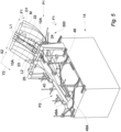
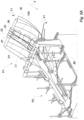
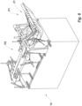
- the appended Figures 1 to 6 show an apparatus 100 according to the invention.
- the apparatus 100 is particularly suitable for forming bags in a flattened form which are provided with a reinforcement element therein, as in the one shown in Figures 7 , 7A and 8 .
- Figures 7 , 7A and 8 show a bag 1 which is produced with the apparatus of the invention in a flattened configuration T and in an erected configuration for use S.
- the bag 1 is produced from a tape material, preferably paper, cardboard or biodegradable material.
- the bag 1 comprises two front walls 5 which face each other, two side walls 6 which face each other, a base 7 and an opening 8.
- a reinforcement element 10 which is intended to be positioned, with the bag in the erected configuration for use S, on the base 7 of the bag 1 and sized so as to at least partially cover the base 7 itself.
- the bag 1 is obtained from a first tape material M which is cut so as to form a strip 2, which is shown in greater detail in Figure 9 and which is suitably shaped and subsequently folded to produce the bag 1.
- the strip 2 is delimited by two opposite longitudinal edges 2A, 2B, which are opposing in the transverse direction X1 of the strip 2 and two opposite transverse edges 2C, 2D which are opposing in the longitudinal direction Y1 of the strip 2, and is provided with intended folding lines 3, which are also known as creases and which allow folding of the strip 2 in order to define the bag 1.
- the creases 3 comprise a plurality of longitudinal creases 3A, a base crease 3B and an upper crease 3C.
- the longitudinal creases 3A define and delimit the front walls 5 and side walls 6 of the bag 1 and allow folding of the strip 2 in order to define the side walls 6 and front walls 5 of the bag.
- Each front wall 5 has a width "W" corresponding to the width of the bag to be formed.
- the strip 2 may be provided with a variable number of longitudinal creases 3A depending on the number of walls of the bag and/or the form of the side walls 6. In the version shown, there are provided six longitudinal creases 3A in order to define four walls in the bag 1 and to allow folding of the side walls 6 in the manner of a bellows between the front walls 5 with the bag 1 in the flattened configuration T.
- the longitudinal creases 3A comprise in particular at least one lateral crease 30 which is capable of defining in each side wall 6 at least two different side wall portions 6A, 6B which can be folded with respect to each other along this lateral crease 30.
- the base crease 3B defines the base 7 of the bag 1, that is to say, allows folding of the strip 2 in order to define the base 7 of the bag 1.
- the upper crease 3C allows folding of the strip 2 in order to close the opening 8 of the bag 1, if desired.
- the upper crease 3C defines on the front walls 5 and side walls 6 closing edges 80 which are intended to be folded and positioned one on the other in order to close the opening 8 of the bag 1.
- the strip 2 is shaped so that the upper crease 3C defines closing edges 80 on at least two opposing walls of the bag 1, in a particularly preferred version the closing edges 80 are defined on the two front walls 5 of the bag 1.
- the upper crease 3B and lower crease 3C are positioned at a distance "D" in the longitudinal direction Y1 of the strip 2 which depends on the dimensions of the bag to be formed.
- the longitudinal creases 3A are produced in such a manner that a front wall 5 is positioned in the central band 51 in the strip 2, the two lateral bands 50 of the strip 2 correspond to the side walls 6 and the other front wall 5 of the bag 1.
- Two lateral edges 9A and 9B of the lateral bands 50 are positioned one on the other in a superimposition zone 9 so as to form a body having a virtually tubular form 200 which is shown in Figure 10 .
- the tubular body 200 is then folded and adhesively bonded in the region of one of the longitudinal ends, forming base folds 70, so as to close the tubular body 200 in the region of this longitudinal end and to form the folds in order to be able to subsequently form the base 7 of the bag 1.
- the corresponding transverse edge 2D is suitably shaped.
- the bag 1 is obtained in a flattened configuration T, as shown in Figures 7 and 7A, with the reinforcement element 10 inserted inside the bag 1 itself.
- the reinforcement element 10 is in a production configuration T1, in which it is supported on one of the front walls 5 of the bag 1 and retained between it and a side wall portion 6A of each of the side walls 6.
- the reinforcement element 10 is positioned so as to be interposed between the lower crease 3B and the upper crease 3C of the strip 2.
- the reinforcement element 10 in the flattened configuration T is positioned in a zone of the bag which is not involved in the folding of the base 70 so as to reduce the spatial requirement of the bags in a flattened configuration T.
- the reinforcement element 10 is positioned so as to be interposed between and retained by a front wall 5 and a side wall portion 6A, 6B.
- Figures 1 to 6 show an apparatus 100 constructed according to the invention suitable for producing a bag which is provided with a reinforcement element.
- the apparatus 100 of the invention comprises a source of a first tape material M and a source of a second tape material N which are intended to form the bag 1 and the reinforcement element 10, respectively.
- the first tape material M and the second tape material N are wound on respective reels 101, 102. Peels having various transverse extents can be used in accordance with the dimensions of the bag to be formed and/or the reinforcement element to be used.
- the first tape material M is unwound in the longitudinal direction Y2 thereof and has a width L1 measured in the transverse direction X2 which is perpendicular to the longitudinal unwinding direction Y2 which is selected on the basis of the dimensions of the bag to be formed.
- the second tape material N is unwound in the longitudinal direction Y3 thereof and has a second width L2 measured in the transverse direction X3 which is perpendicular to the longitudinal unwinding direction Y3 which is selected on the basis of the dimensions of the bag to be formed.
- the second width L2 of the second tape material N is less than the width L1 of the first tape material M so that the reinforcement element 10 can be inserted in the bag 1, as better explained below.
- the second width L2 of the second tape material N almost corresponds to the width W of the front wall 5 of the bags being formed.
- the first tape material M and the second tape material N are preferably selected from a group comprising paper or card, preferably the second tape material N has a thickness greater than the first tape material M.
- the apparatus 100 comprises a first unwinding device 103 in order to unwind the first tape material M from the first reel 101 and to advance it through the processing stations which are provided in the apparatus 1 along a processing path P in such a manner that it is subjected to the operations necessary for the formation of a bag 1.
- the first tape material M is moved in the advance direction which is indicated by the arrow F in the Figures along the processing path P inside the apparatus 100.
- the first unwinding device 103 is configured in such a manner that the first tape material M is moved at an advance speed VA which depends on the productivity of the apparatus 100 and which can be defined during the configuration of the apparatus 100 itself.
- the apparatus 100 further comprises a second unwinding device 104 in order to unwind the second tape material N from the second reel 102 and to advance it in the direction of the advance arrow F inside the apparatus 100.
- the second unwinding device 104 is configured in such a manner that the second tape material N is moved at a second advance speed VB less than the first advance speed VA, VB ⁇ VA.
- the ratio between the first advance speed and second advance speed VA/VB depends on the dimensions of the bag 1 to be formed, the dimensions of the base 7 of the bag 1 to be formed and the dimensions of the reinforcement element 10 which it is desired to construct.
- the first unwinding device 103 comprises a plurality of pulling devices 105 which are spaced apart along the processing path P and which are arranged to pull the first tape material M and a plurality of advance rollers 106 which are spaced apart along the processing path and on which the first tape material M is conveyed in order to be guided along the processing path P.
- the advance rollers 106 may be idle rollers and may be caused to rotate by the pulling devices 105 in order to advance the first tape material M in the direction of the arrow F.
- the first unwinding device 103 further comprises redirecting rollers in order to define the desired path for the first tape material M in the apparatus 100.
- the apparatus 100 comprises a printing station which is not shown and in which the first tape material M is pulled in order to be printed in order to produce any decorations on the bag being formed.
- the printing station may not be provided.
- the apparatus 100 further comprises a drilling station 12 in which the first tape material M is drilled so as to produce intended breaking points, for example, the intended breaking points 120 shown in Figure 10 , in the region of which the first tape material M is subsequently separated so as to define the strips 2 in order to construct the bag 1.
- intended breaking points for example, the intended breaking points 120 shown in Figure 10
- the intended breaking points 120 are capable of defining the transverse edges 2C, 2D of the strip 2, as better explained below.
- the drilling devices provided at the drilling station 12, which are not shown in detail in the Figures, are positioned so as to define on the first tape material M a strip 2 having the desired shape which is dependent on the form of the bag to be formed, for example, similar to the one shown in Figure 9 .
- the drilling devices are controlled so as to intercept the first tape material M at predetermined time intervals which depend on the dimensions of the bag to be formed.
- the drilling station 12 is positioned downstream of the printing station 11 if it is provided.
- the apparatus 100 further comprises a forming station 14 which is positioned downstream of the drilling station 12 and which is shown in greater detail in Figures 2 to 6 , in which the first tape material M is folded in order to form a continuous tubular body 200, as better described below.
- the advance rollers 106 are arranged so as to define an advancing path for the first tape material M passing close to a cutting station 13 of the apparatus 100, as better explained below.
- the apparatus 100 further comprises a cutting station 13 which is positioned upstream of the forming station 14 and to which the second tape material N is pulled by means of second pulling devices 107 of the second unwinding device 104 and in which the second tape material N is cut into a plurality of sheets 10A, which can better be seen in Figures 5 and 5A , each one being intended to form the support element 10 of the bag 1.
- the cutting station 13 is provided with a cutting device 130 which is actuated at predefined time intervals t1 which can be adjusted so as to generate sheets 10A and therefore support elements 10 having a desired longitudinal extent "01".
- the cutting device 130 is controlled by a timer which is not shown in the Figures and which controls the cutting interval t1.
- the cutting interval t1 is timed on the basis of the dimensions of the base 7 of the bag 1 to be produced and the longitudinal dimensions of the bag 1 to be produced.
- the cutting device 130 is actuated so as to obtain sheets 10A having a longitudinal extent D1 less than or equal to the width D4 of the base 7 of the bag 1, which is preferably approximately 80-99% of the width D4 of the base 7.
- a coupling device 20 which is intended to couple the sheets 10A of the second tape material N to the first tape material M, as better described below.
- the coupling device 20 is intended to receive the first tape material M which is moved by the unwinding device 103 towards the forming station 14 and the sheets 10A of the second tape material N being discharged from the cutting station 13 and to couple them to each other in order to supply them in the coupled state to the forming station 14.
- the coupling device 20 allows the sheets 10A to be coupled to the first tape material M in such a manner that they are positioned in the desired position on the first tape material M, as better explained below, and allows them to be fixed in this position until they are introduced into the forming station 14.
- the coupling device 20 is configured to couple the sheets 10A to the first tape material M in a stable but removable manner and without using adhesives or other permanent securing elements.
- the coupling device 20 couples the sheets 10A to the first tape material M in such a manner that there is provided a sheet 10A for each of the bags 1 being formed.
- the sheets 10A and the first tape material M are supplied to the coupling device 20 in such a manner that the sheets 10A are positioned on the first tape material M in a central position in the transverse direction X2 thereof, that is to say, in the central band 51 of the strip 2.
- the sheets 10A are positioned in a position which will not be involved in folding during the forming of the bags so as to facilitate the forming of the bags themselves.
- Each sheet 10A is positioned on the first tape material M so as to be arranged between the upper crease 3B and lower crease 3C of each of the bags 1 being formed.
- the sheets 10A and the first tape material M are moved at the advance speed VA of the first tape material M.
- the coupling device 20 comprises a plurality of coupling rollers 20A which define a path along the coupling device 20 for the first tape material M and for the sheets 10A which is formed so as to allow coupling therebetween.
- the coupling device 20 further comprises a guide device 21 for guiding the sheets 10A of the second tape material N along the coupling device 20 in such a manner that the sheets 10A are supported on and coupled to the first tape material M, as better explained below.
- the guide device 21 is positioned in such a manner that the sheets 10A are interposed between the guide device 21 and the first tape material M being moved towards the forming station 14.
- the guide device 21 allows the sheets 10A of the second tape material N to be guided in order to move the sheets 10A of the second tape material N and the first tape material M together in the advance direction F as far as the forming station 14.
- the guide device 21 is positioned so as to keep the sheets 10A of the second tape material N bonded to the first tape material M.
- the guide device 21 prevents the sheets 10A from moving with respect to the first tape material M during the advance from the cutting station 13 to the forming station 14.
- the guide device 21 is intended to guide the sheets 10A of the second tape material N along at least one portion P1 of the processing path P which is preferably positioned upstream of the forming station 14 and downstream of the cutting station 13.
- the guide device 21 comprises two belts 22, 23 which are provided in positions spaced apart in the transverse direction X2 of the first tape material M and which are intended to interact with the sheets 10A of the second tape material N in order to keep it bonded to the first tape material M.
- Each belt 22, 23 is wound between a respective pair of wheels which can be rotated in the direction of the arrow F1 in such a manner that the respective belt 22, 23 can slide on the wheels of the respective pair.
- Each pair of wheels comprises a proximal wheel 24, 25 which is positioned in a proximal position with respect to the forming station 14 and a distal wheel 26, 27 which is positioned in a position further away from the forming station 14 than the proximal wheel 24, 25.
- Each wheel 24, 25, 26, 27 is advantageously provided on the outer surface thereof with at least one circumferential channel 24A, 25A, 26A, 27A for receiving the respective belt 22, 23.
- connection between the belts and the respective wheels to be kept stable so as to prevent undesirable movements of the belts themselves during the operation of the apparatus 100.
- each pair of wheels there may be provided for each pair of wheels a plurality of belts which are spaced apart in the transverse direction so as to further increase the stability of the sheets 10A on the first tape material M.
- This arrangement makes it readily possible to guide sheets 10A having mutually different dimensions with the guide device 21.
- the wheels can be advantageously provided with corresponding channels.
- the guide device 21 is further provided with an adjustment device which is not shown in the Figures and which is intended to adjust the transverse distance between the wheels and therefore between the belts.
- the two proximal wheels 24, 25 and the two distal wheels 26, 27 are positioned with mutual spacing corresponding to the width W of the bag to be formed, that is to say, of the central band 51.
- the lateral bands 50 of the first tape material M are free to be folded with respect to the guide device 21 so as to progressively form the tubular body 200.
- the wheels 24, 25, 26, 27 are positioned in such a manner that the belts 22, 23 extend between the cutting station 13 and the forming station 14.
- the belts 22, 23 are facing the first tape material M, the sheets 10A being interposed between the belts 22, 23 and the first tape material M.
- the wheels 24, 25, 26, 27 are actuated in such a manner that the belts 22, 23 slide in a direction in accordance with the advance direction F of the first tape material M and at the same speed as the tape material M so as not to generate relative sliding actions between the sheets 10A and the first tape material M.
- the belts 22, 23 keep the sheets 10A bonded to the first tape material M in the desired position.
- the coupling device 20 further comprises an accompanying device 300 which is interposed between the proximal wheels 24, 25 and the forming station 14 and which is arranged to accompany the sheets 10A of the second tape material N of the forming station 14.
- the accompanying device 300 receives the first tape material M and the sheets 10A coupled thereto from the coupling device 20 and accompanies them as far as the forming station 14.
- the accompanying device 300 comprises, in the region of each proximal wheel 24, 25, a crescent-like member 32 which is fixed to the rotation pin 31 of the corresponding proximal wheel 24, 25 and a plate 33 which extends between the proximal wheel 24, 25 and the forming station 14.
- the plate 33 is preferably metal and has such dimensions as to extend between the crescent-like member 32 and the forming station 14.
- the sheets 10A of the second tape material N are accompanied by means of the accompanying device 300 by the guide device 21 as far as the forming station 14.
- the first tape material M passes around the crescent-like member 32 and the sheets 10A are interposed between the first tape material M and the crescent-like member 32 and between the plate 33 and the first tape material M.
- the plate 33 has such dimensions as to extend as far as the opening of the forming station 14 so as to prevent movements of the sheets 10A of the second tape material N before reaching the forming station 14.
- the presence of the accompanying device 300 allows the first tape material M and the sheets 10A to be kept coupled as far as the inlet of the forming station 14.
- the coupling device 20 is positioned so as to define a portion P1 of the processing path P which is inclined with respect to the additional portion P2 of the processing path P which is defined in the forming station 14.
- the path of the first tape material M is redirected and this redirection makes it easier to fold the first tape material M in order to form the tubular body 200. Since, as mentioned above, the guide device 21 interacts only with the central band 51 of the first tape material M which is intended to form a front wall 5 of the bag 1, the lateral bands 50 of the first tape material M are free to be folded with respect to the guide device 21.
- the apparatus 100 further comprises a gluing device 16 which is intended to apply a desired adhesive to at least one of the two lateral edges 9A and 9B of the first tape material M in order to be able to secure them to each other in the superimposition zone 9.
- the gluing device 16 is provided upstream of the forming station 14, advantageously in the region of the coupling device 20.
- the forming station 14 comprises a first forming plate 41 and a second forming plate 42, which are shown in greater detail in Figures 2 and 4 and which extend in the advance direction F of the apparatus 1 and on which there is wound the first tape material M in order to form a tubular body.
- the first plate 41 and the second plate 42 are, with a horizontal positioning of the apparatus 100, spaced apart from each other along a vertical axis Z and are positioned in such a manner that the first plate 41 is interposed between the second plate 42 and the ground.
- the first plate 41 which, with a horizontal positioning of the apparatus 100, is nearer the ground extends substantially parallel with a horizontal axis Y' of the apparatus 100, the second plate 42 is inclined with respect to the horizontal axis Y' in the advance direction F.
- first plate 41 and the second plate 42 are inclined with respect to each other in the advance direction F.
- the first plate 41 and the second plate 42 are positioned in such a manner that there is defined therebetween an opening "B" having decreasing dimensions in the advance direction F.
- the angle of inclination between the second plate 42 and the horizontal Y' is selected on the basis of the dimensions of the bag to be formed and in particular of the side walls 6 thereof.
- the forming station 14 is provided with adjustment elements which cannot be seen in order to adjust the mutual spacing between the first plate 41 and the second plate 42 and/or to adjust the inclination of the second forming plate 42.
- the first tape material M is supplied in such a manner that a central band 51 thereof faces the first plate and the sheets 10A of the second tape material N are interposed between the first tape material M and the first plate 41.
- the first plate 41 and the second plate 42 have a width X4 measured in the transverse direction X2 of the first tape material M which virtually corresponds to the width W of the bag 1 to be formed.
- the first plate 41 and the second plate 42 have a width X4 less than the width W of the bag 1 to be formed, preferably approximately 99-90% of the width "W" of the bag 1 to be formed.
- the first plate 41 and the second plate 42 have a width X4 which increases in the advance direction F so that the width X4 of the first plate 41 and the second plate 42 at the outlet of the forming station virtually corresponds to the width W of the bag 1.
- the first plate 41 has a concave shape in the transverse direction X with the concavity directed towards the second plate 42.
- this formation prevents the use of pushing elements in order to push the first tape material M towards the first plate 41 and to keep it bonded thereto.
- the first plate 41 is delimited at the opening of the forming station 14, that is to say, at the end directed towards the coupling device 20, by a rounded edge 41A.
- the rounded edge 41A defines the opening of the forming station 14.
- the rounded edge 41A is advantageously curved towards the coupling device 20 in order to improve the connection between the guide device 21 or the accompanying device 300, when present, and the forming station 14 and to prevent jams of the first tape material M.
- the rounded formation of the edge 41A prevents jams of the first tape material M and/or the second tape material N being introduced into the forming station 14.
- the plates 33 are positioned so as to be supported on the first plate 41 in order to guide the sheets 10A of the second tape material N on the first plate 41.
- the plates 33 are positioned in such a manner that the sheets 10A slide between the plates 33 and are interposed between them and the first tape material M.
- the sheets 10A are interposed between the first tape material M and a face of the first plate 41 and the relative movement between the sheets 10A and the first tape material M is thereby prevented.
- the forming station 14 is further provided with an accompanying device 43 for accompanying the winding of the first tape material M on the plates 41, 42.
- the accompanying device 43 comprises at least one pair of accompanying elements which are arranged at opposite sides in the transverse direction X of the forming station 14 and which are intended to engage with the transversely opposed lateral bands 50 of the first tape material M in order to accompany them towards the forming plates 41, 42.
- the accompanying elements are provided at the opening of the forming station 14.
- Each accompanying element comprises, in the form shown, an arm 44A, 44B which is hinged on a support pin, which is not shown, and which is intended to intercept the first tape material M being discharged from the guide device 21 in order to accompany it towards the plates 41, 42.
- the forming station 14 does not have any accompanying device.
- the forming station 14 further comprises a folding device 45 in order to fold the edges of the first tape material M on the second plate 42 in order to form the tubular body 200.
- the folding device 45 comprises a plurality of pairs of pressing rollers 48, the rollers of each pair of pressing rollers being spaced apart from each other in a transverse direction so as to engage with opposite edges of the first tape material M.
- the pairs of rollers 48 are positioned in the advance direction F.
- the pressing rollers 48A of the pairs of pressing rollers 48 are intended to intercept the edges of the first tape material M and to fold them on the second plate 42 so as to superimpose the two lateral edges 9A and 9B one on the other in the superimposition zone 9 in order to form a tubular body 200. Since at least one of the two lateral edges 9A and 9B is provided with adhesive, they are mutually attached and there is progressively defined a tubular body 200.
- the pressing rollers 48A are further intended to press the lateral edges 9A and 9B in the superimposition zone 9 in order to promote the adhesive bonding of the lateral edges 9A and 9B in order to form the tubular body 200.
- the pressing rollers 48A are fixed to an adjustment element in order to adjust the position thereof with respect to the first tape material M and to adjust the pressure which acts thereon.
- the position of the pressing rollers 48A of each pair of pressing rollers 48 is adjusted in an independent manner from each other.
- the forming station 14 further comprises a forming device 46 which is intended to fold the first tape material M in order to define the side walls 6 of the bag 1 being formed.
- the forming device 46 is intended to fold the first tape material M by inserting it inside the opening "B" between the first plate 41 and the second plate 42.
- the forming device 46 comprises at least one pair of forming wheels 47A, 47B which are arranged at opposite sides in a transverse direction X of the forming station 14 and which are intended to interact with transversely opposite portions of the first tape material M in order to insert them in the opening B between the plates 41, 42.
- the forming wheels 47A, 47B allow definition of the longitudinal creases 3A of the side walls 6 in order to fold the side walls 6 in the manner of a bellows between the plates 41, 42.
- the forming device 46 comprises a plurality of pairs of forming wheels which are spaced apart in the advance direction F.
- the forming wheels 47A, 47B are idle wheels on the individual rotation pin and are caused to rotate by being drawn by the contact with the first tape material M.
- the wheels of the pairs of wheels 47 are positioned with mutual spacing in the transverse direction which decreases in the advance direction F so as to progressively fold the two side wall portions 6A, 6B at the inner side between the front walls 5.
- the sheets 10A of the second tape material N are thus blocked in the region of the central portion W of the first tape material M, being interposed between the front wall 5 and a side wall portion 6A, 6B of each side wall 6.
- the folding of the side walls at the inner side between the front walls allows the sheets 10A of the second tape material N to be kept positioned in a stable manner.
- the forming station 14 comprises at least one support roller 85, which can be seen in Figure 5A and which is arranged under the first plate 41, that is to say, in such a manner that the first plate 41 is interposed between the support roller 85 and the ground.
- the support roller 85 is arranged to accompany the first tape material M along the forming station 14, keeping it stretched and bonded to the first plate 41.
- a tubular body 200 having a width which corresponds to the width W of the front walls 5 of the bag 1 being formed, with the side walls 6 folded in the manner of a bellows between the two front walls 5 and the sheets 10A of the second tape material N inserted between a front wall 5 and the side wall portions 6A, 6B which are directed towards it.
- the tubular body 200 has the side wall portions 6A, 6B folded in the manner of a bellows towards the inner side and is provided at the inner side thereof, at predefined longitudinal intervals, with sheets 10A of the second tape material N, as better shown in Figure 10 .
- tubular body 200 and in particular the presence of the lateral bellows-like arrangement prevents the undesirable movement of the sheets 10A of the second tape material N.
- the second tape material N is in fact kept stable by the bellows-like arrangement of the side walls 6 and compressed between the two front walls 5 of the bag 1 being formed.
- a single forming plate in the forming station 14 there is provided a single forming plate.
- This version is particularly suitable for producing bags with a non-parallelepipedal form, in which the two front walls are connected to each other and the side walls are not provided.
- the apparatus 100 further comprises downstream of the forming station 14 a separation station 15 in which the tubular body 200 is separated at intended breaking points 120 so as to generate different tubular portions 201, each one suitable for forming a single bag 1.
- the apparatus 100 further comprises a gluing station 17, at which the lower edges of the strip 2 are adhesively bonded and subsequently folded to form the base folds 70.
- the sheets 10A are, as mentioned, in a production configuration T1, in which each sheet 10A is supported on a front wall 5 of the bag being formed and retained in this position by a side wall portion 6A of each side wall 6.
- the sheet 10A is rotated, being supported on the base 7, bringing it into the configuration for use S1, in which the sheet is positioned on the base of the bag and acts as a reinforcement element 10 thereof. Therefore, a strong bag which is reinforced is obtained.
- the apparatus and the method of the invention achieve the objects set out, allowing a number of advantages to be achieved.
- Bags in a flattened configuration having a small spatial requirement are obtained.
- Bags in a flattened configuration having a reinforcement element which is positioned in the desired position so as to allow a simple preparation of the bag in an erected configuration are obtained.
- the bags obtained do not have internal tensions or breaks as a result of the movement of the reinforcement element 10 in order to be moved from the production configuration, in which it is interposed between the front wall 5 and a side wall portion 6A, 6B, and the configuration for use, in which it is superimposed on the base 7 of the bag 1.
Landscapes
- Making Paper Articles (AREA)
Priority Applications (3)
| Application Number | Priority Date | Filing Date | Title |
|---|---|---|---|
| SI201930717T SI3847010T1 (sl) | 2018-09-03 | 2019-07-24 | Naprava in postopek za oblikovanje vrečk z ojačitvenim vložkom |
| HRP20240292TT HRP20240292T1 (hr) | 2018-09-03 | 2019-07-24 | Aparat i postupak za formiranje vrećica sa umetkom za ojačanje |
| RS20240252A RS65346B1 (sr) | 2018-09-03 | 2019-07-24 | Aparat i postupak za formiranje kesa sa umetkom za ojačanje |
Applications Claiming Priority (2)
| Application Number | Priority Date | Filing Date | Title |
|---|---|---|---|
| IT201800008310 | 2018-09-03 | ||
| PCT/IB2019/056318 WO2020049376A1 (en) | 2018-09-03 | 2019-07-24 | Apparatus and method for forming bags with a reinforcement insert |
Publications (2)
| Publication Number | Publication Date |
|---|---|
| EP3847010A1 EP3847010A1 (en) | 2021-07-14 |
| EP3847010B1 true EP3847010B1 (en) | 2023-11-29 |
Family
ID=64316813
Family Applications (1)
| Application Number | Title | Priority Date | Filing Date |
|---|---|---|---|
| EP19758513.6A Active EP3847010B1 (en) | 2018-09-03 | 2019-07-24 | Apparatus and method for forming bags with a reinforcement insert |
Country Status (8)
| Country | Link |
|---|---|
| EP (1) | EP3847010B1 (pl) |
| ES (1) | ES2973345T3 (pl) |
| HR (1) | HRP20240292T1 (pl) |
| HU (1) | HUE065901T2 (pl) |
| PL (1) | PL3847010T3 (pl) |
| RS (1) | RS65346B1 (pl) |
| SI (1) | SI3847010T1 (pl) |
| WO (1) | WO2020049376A1 (pl) |
Cited By (1)
| Publication number | Priority date | Publication date | Assignee | Title |
|---|---|---|---|---|
| WO2026033491A1 (en) * | 2024-08-09 | 2026-02-12 | Lineapack Chinello S.R.L. | Apparatus and method for constructing a bag |
Families Citing this family (7)
| Publication number | Priority date | Publication date | Assignee | Title |
|---|---|---|---|---|
| CN112406189A (zh) * | 2020-11-10 | 2021-02-26 | 安庆市众友塑料包装有限公司 | 一种环保塑料袋生产用压平机构 |
| CN112976688B (zh) * | 2021-04-28 | 2025-07-25 | 苏州海蓝环保科技有限公司 | 一种除尘器滤袋袋体成型机 |
| FR3122847B1 (fr) * | 2021-05-12 | 2023-05-12 | Holweg Group | Procédé et machine de fabrication de sac flexible du type enveloppe, notamment avec renfort |
| US20240239558A1 (en) | 2021-05-12 | 2024-07-18 | Holweg Group | Flexible bag having a convertible bottom, method and machine for manufacturing same |
| CN113334859B (zh) * | 2021-06-08 | 2022-11-18 | 惠州益栢科技有限公司 | 一种基于制袋机的中封包装袋生产方法 |
| FR3129872B1 (fr) * | 2021-12-02 | 2024-09-13 | Coveris Flexibles France | Sac d’emballage de produits alimentaires et résistant aux graisses, et procédé de fabrication d’un tel sac |
| CN118205262B (zh) * | 2024-05-21 | 2024-09-27 | 海门市知行包装制品有限公司 | 一种物料包装袋的翻折输送机 |
Family Cites Families (3)
| Publication number | Priority date | Publication date | Assignee | Title |
|---|---|---|---|---|
| CA450345A (en) * | 1941-05-01 | 1948-08-03 | A. Wolf Howard | Method and apparatus for making paper bags |
| US5158371A (en) * | 1990-05-29 | 1992-10-27 | Moravek Lawrence R | Self-supporting polymer bag and method of manufacture |
| EP1728732A1 (en) * | 2005-06-01 | 2006-12-06 | Imball-Center S.r.l. | Thermal insulating bag |
-
2019
- 2019-07-24 EP EP19758513.6A patent/EP3847010B1/en active Active
- 2019-07-24 WO PCT/IB2019/056318 patent/WO2020049376A1/en not_active Ceased
- 2019-07-24 HR HRP20240292TT patent/HRP20240292T1/hr unknown
- 2019-07-24 PL PL19758513.6T patent/PL3847010T3/pl unknown
- 2019-07-24 HU HUE19758513A patent/HUE065901T2/hu unknown
- 2019-07-24 RS RS20240252A patent/RS65346B1/sr unknown
- 2019-07-24 ES ES19758513T patent/ES2973345T3/es active Active
- 2019-07-24 SI SI201930717T patent/SI3847010T1/sl unknown
Cited By (1)
| Publication number | Priority date | Publication date | Assignee | Title |
|---|---|---|---|---|
| WO2026033491A1 (en) * | 2024-08-09 | 2026-02-12 | Lineapack Chinello S.R.L. | Apparatus and method for constructing a bag |
Also Published As
| Publication number | Publication date |
|---|---|
| HRP20240292T1 (hr) | 2024-05-24 |
| SI3847010T1 (sl) | 2024-05-31 |
| ES2973345T3 (es) | 2024-06-19 |
| HUE065901T2 (hu) | 2024-06-28 |
| WO2020049376A1 (en) | 2020-03-12 |
| RS65346B1 (sr) | 2024-04-30 |
| PL3847010T3 (pl) | 2024-06-10 |
| EP3847010A1 (en) | 2021-07-14 |
Similar Documents
| Publication | Publication Date | Title |
|---|---|---|
| WO2020049376A1 (en) | Apparatus and method for forming bags with a reinforcement insert | |
| US12023890B2 (en) | Method and system for manufacturing bags | |
| US4328655A (en) | Method of manufacturing a packaged web product and apparatus therefor | |
| RU2446052C1 (ru) | Установка для производства пластиковых пакетов | |
| CN107530998B (zh) | 用于形成包装件的方法和系统 | |
| ITBO20000733A1 (it) | Macchina per il confezionamento di pile di articoli multi - falda di carta o simili entro relativi involucri ottenuti da fogli di avvolgimen | |
| RU2039684C1 (ru) | Способ упаковывания типографских изделий | |
| TWI548510B (zh) | 用於製袋機之捆箍器以及用於捆箍一輥的袋件之方法 | |
| JP2024540160A (ja) | パウチ包装の製造装置および製造方法 | |
| US4605464A (en) | Method and machine for producing complance carrier cartons | |
| JP2009520650A (ja) | 側縁折込みを形成する手段を含むフィルムフード包装装置 | |
| US4215626A (en) | Method and apparatus for manufacturing articles made of paper from a plurality of pre-perforated strips | |
| US9902587B2 (en) | Method and apparatus for fabricating stretch film rolls | |
| US6298634B1 (en) | Process and device for producing a wound roll that is wrapped on its circumference, and the wound roll | |
| CA2224533A1 (en) | Bag-folding apparatus | |
| JP6187805B2 (ja) | 包装装置 | |
| WO2026033491A1 (en) | Apparatus and method for constructing a bag | |
| CN114161772B (zh) | 一种蜂窝信封袋生产工艺及设备 | |
| WO2023061776A1 (de) | Verfahren und vorrichtung zur herstellung einer gebindepackung für hygieneprodukte und entsprechende gebindepackung | |
| JPH11348152A (ja) | 伸縮性を有する不織網地又は織網地よりなるシートにヘッダー部を融着して製袋する製袋機及び製袋方法 | |
| CA2856999A1 (en) | Method and apparatus for fabricating stretch film rolls | |
| JPH04314597A (ja) | 連続封筒用フォーム | |
| AU2001291516A1 (en) | Treating fabric for manufacturing filter bags |
Legal Events
| Date | Code | Title | Description |
|---|---|---|---|
| REG | Reference to a national code |
Ref country code: HR Ref legal event code: TUEP Ref document number: P20240292T Country of ref document: HR |
|
| STAA | Information on the status of an ep patent application or granted ep patent |
Free format text: STATUS: UNKNOWN |
|
| STAA | Information on the status of an ep patent application or granted ep patent |
Free format text: STATUS: THE INTERNATIONAL PUBLICATION HAS BEEN MADE |
|
| PUAI | Public reference made under article 153(3) epc to a published international application that has entered the european phase |
Free format text: ORIGINAL CODE: 0009012 |
|
| STAA | Information on the status of an ep patent application or granted ep patent |
Free format text: STATUS: REQUEST FOR EXAMINATION WAS MADE |
|
| 17P | Request for examination filed |
Effective date: 20210226 |
|
| AK | Designated contracting states |
Kind code of ref document: A1 Designated state(s): AL AT BE BG CH CY CZ DE DK EE ES FI FR GB GR HR HU IE IS IT LI LT LU LV MC MK MT NL NO PL PT RO RS SE SI SK SM TR |
|
| DAV | Request for validation of the european patent (deleted) | ||
| DAX | Request for extension of the european patent (deleted) | ||
| GRAP | Despatch of communication of intention to grant a patent |
Free format text: ORIGINAL CODE: EPIDOSNIGR1 |
|
| STAA | Information on the status of an ep patent application or granted ep patent |
Free format text: STATUS: GRANT OF PATENT IS INTENDED |
|
| RIC1 | Information provided on ipc code assigned before grant |
Ipc: B31B 70/00 20170101ALI20230525BHEP Ipc: B31B 160/20 20170101ALI20230525BHEP Ipc: B31B 155/00 20170101ALI20230525BHEP Ipc: B31B 70/36 20170101ALI20230525BHEP Ipc: B31B 70/26 20170101ALI20230525BHEP Ipc: B31B 70/10 20170101ALI20230525BHEP Ipc: B31B 70/04 20170101AFI20230525BHEP |
|
| INTG | Intention to grant announced |
Effective date: 20230614 |
|
| P01 | Opt-out of the competence of the unified patent court (upc) registered |
Effective date: 20230601 |
|
| GRAS | Grant fee paid |
Free format text: ORIGINAL CODE: EPIDOSNIGR3 |
|
| GRAA | (expected) grant |
Free format text: ORIGINAL CODE: 0009210 |
|
| STAA | Information on the status of an ep patent application or granted ep patent |
Free format text: STATUS: THE PATENT HAS BEEN GRANTED |
|
| AK | Designated contracting states |
Kind code of ref document: B1 Designated state(s): AL AT BE BG CH CY CZ DE DK EE ES FI FR GB GR HR HU IE IS IT LI LT LU LV MC MK MT NL NO PL PT RO RS SE SI SK SM TR |
|
| REG | Reference to a national code |
Ref country code: GB Ref legal event code: FG4D |
|
| REG | Reference to a national code |
Ref country code: CH Ref legal event code: EP |
|
| REG | Reference to a national code |
Ref country code: DE Ref legal event code: R096 Ref document number: 602019042403 Country of ref document: DE |
|
| REG | Reference to a national code |
Ref country code: IE Ref legal event code: FG4D |
|
| REG | Reference to a national code |
Ref country code: LT Ref legal event code: MG9D |
|
| REG | Reference to a national code |
Ref country code: NL Ref legal event code: MP Effective date: 20231129 |
|
| PG25 | Lapsed in a contracting state [announced via postgrant information from national office to epo] |
Ref country code: GR Free format text: LAPSE BECAUSE OF FAILURE TO SUBMIT A TRANSLATION OF THE DESCRIPTION OR TO PAY THE FEE WITHIN THE PRESCRIBED TIME-LIMIT Effective date: 20240301 |
|
| PG25 | Lapsed in a contracting state [announced via postgrant information from national office to epo] |
Ref country code: IS Free format text: LAPSE BECAUSE OF FAILURE TO SUBMIT A TRANSLATION OF THE DESCRIPTION OR TO PAY THE FEE WITHIN THE PRESCRIBED TIME-LIMIT Effective date: 20240329 |
|
| PG25 | Lapsed in a contracting state [announced via postgrant information from national office to epo] |
Ref country code: LT Free format text: LAPSE BECAUSE OF FAILURE TO SUBMIT A TRANSLATION OF THE DESCRIPTION OR TO PAY THE FEE WITHIN THE PRESCRIBED TIME-LIMIT Effective date: 20231129 |
|
| PG25 | Lapsed in a contracting state [announced via postgrant information from national office to epo] |
Ref country code: LT Free format text: LAPSE BECAUSE OF FAILURE TO SUBMIT A TRANSLATION OF THE DESCRIPTION OR TO PAY THE FEE WITHIN THE PRESCRIBED TIME-LIMIT Effective date: 20231129 Ref country code: IS Free format text: LAPSE BECAUSE OF FAILURE TO SUBMIT A TRANSLATION OF THE DESCRIPTION OR TO PAY THE FEE WITHIN THE PRESCRIBED TIME-LIMIT Effective date: 20240329 Ref country code: GR Free format text: LAPSE BECAUSE OF FAILURE TO SUBMIT A TRANSLATION OF THE DESCRIPTION OR TO PAY THE FEE WITHIN THE PRESCRIBED TIME-LIMIT Effective date: 20240301 Ref country code: BG Free format text: LAPSE BECAUSE OF FAILURE TO SUBMIT A TRANSLATION OF THE DESCRIPTION OR TO PAY THE FEE WITHIN THE PRESCRIBED TIME-LIMIT Effective date: 20240229 |
|
| PG25 | Lapsed in a contracting state [announced via postgrant information from national office to epo] |
Ref country code: NL Free format text: LAPSE BECAUSE OF FAILURE TO SUBMIT A TRANSLATION OF THE DESCRIPTION OR TO PAY THE FEE WITHIN THE PRESCRIBED TIME-LIMIT Effective date: 20231129 |
|
| REG | Reference to a national code |
Ref country code: HR Ref legal event code: T1PR Ref document number: P20240292 Country of ref document: HR |
|
| PG25 | Lapsed in a contracting state [announced via postgrant information from national office to epo] |
Ref country code: SE Free format text: LAPSE BECAUSE OF FAILURE TO SUBMIT A TRANSLATION OF THE DESCRIPTION OR TO PAY THE FEE WITHIN THE PRESCRIBED TIME-LIMIT Effective date: 20231129 Ref country code: NO Free format text: LAPSE BECAUSE OF FAILURE TO SUBMIT A TRANSLATION OF THE DESCRIPTION OR TO PAY THE FEE WITHIN THE PRESCRIBED TIME-LIMIT Effective date: 20240229 Ref country code: NL Free format text: LAPSE BECAUSE OF FAILURE TO SUBMIT A TRANSLATION OF THE DESCRIPTION OR TO PAY THE FEE WITHIN THE PRESCRIBED TIME-LIMIT Effective date: 20231129 Ref country code: LV Free format text: LAPSE BECAUSE OF FAILURE TO SUBMIT A TRANSLATION OF THE DESCRIPTION OR TO PAY THE FEE WITHIN THE PRESCRIBED TIME-LIMIT Effective date: 20231129 |
|
| REG | Reference to a national code |
Ref country code: AT Ref legal event code: UEP Ref document number: 1635714 Country of ref document: AT Kind code of ref document: T Effective date: 20231129 |
|
| REG | Reference to a national code |
Ref country code: ES Ref legal event code: FG2A Ref document number: 2973345 Country of ref document: ES Kind code of ref document: T3 Effective date: 20240619 |
|
| REG | Reference to a national code |
Ref country code: HU Ref legal event code: AG4A Ref document number: E065901 Country of ref document: HU |
|
| PG25 | Lapsed in a contracting state [announced via postgrant information from national office to epo] |
Ref country code: DK Free format text: LAPSE BECAUSE OF FAILURE TO SUBMIT A TRANSLATION OF THE DESCRIPTION OR TO PAY THE FEE WITHIN THE PRESCRIBED TIME-LIMIT Effective date: 20231129 |
|
| PG25 | Lapsed in a contracting state [announced via postgrant information from national office to epo] |
Ref country code: CZ Free format text: LAPSE BECAUSE OF FAILURE TO SUBMIT A TRANSLATION OF THE DESCRIPTION OR TO PAY THE FEE WITHIN THE PRESCRIBED TIME-LIMIT Effective date: 20231129 |
|
| PG25 | Lapsed in a contracting state [announced via postgrant information from national office to epo] |
Ref country code: SK Free format text: LAPSE BECAUSE OF FAILURE TO SUBMIT A TRANSLATION OF THE DESCRIPTION OR TO PAY THE FEE WITHIN THE PRESCRIBED TIME-LIMIT Effective date: 20231129 |
|
| PG25 | Lapsed in a contracting state [announced via postgrant information from national office to epo] |
Ref country code: SM Free format text: LAPSE BECAUSE OF FAILURE TO SUBMIT A TRANSLATION OF THE DESCRIPTION OR TO PAY THE FEE WITHIN THE PRESCRIBED TIME-LIMIT Effective date: 20231129 Ref country code: SK Free format text: LAPSE BECAUSE OF FAILURE TO SUBMIT A TRANSLATION OF THE DESCRIPTION OR TO PAY THE FEE WITHIN THE PRESCRIBED TIME-LIMIT Effective date: 20231129 Ref country code: EE Free format text: LAPSE BECAUSE OF FAILURE TO SUBMIT A TRANSLATION OF THE DESCRIPTION OR TO PAY THE FEE WITHIN THE PRESCRIBED TIME-LIMIT Effective date: 20231129 Ref country code: DK Free format text: LAPSE BECAUSE OF FAILURE TO SUBMIT A TRANSLATION OF THE DESCRIPTION OR TO PAY THE FEE WITHIN THE PRESCRIBED TIME-LIMIT Effective date: 20231129 Ref country code: CZ Free format text: LAPSE BECAUSE OF FAILURE TO SUBMIT A TRANSLATION OF THE DESCRIPTION OR TO PAY THE FEE WITHIN THE PRESCRIBED TIME-LIMIT Effective date: 20231129 |
|
| PG25 | Lapsed in a contracting state [announced via postgrant information from national office to epo] |
Ref country code: PT Free format text: LAPSE BECAUSE OF FAILURE TO SUBMIT A TRANSLATION OF THE DESCRIPTION OR TO PAY THE FEE WITHIN THE PRESCRIBED TIME-LIMIT Effective date: 20240401 |
|
| REG | Reference to a national code |
Ref country code: HR Ref legal event code: ODRP Ref document number: P20240292 Country of ref document: HR Payment date: 20240711 Year of fee payment: 6 |
|
| PG25 | Lapsed in a contracting state [announced via postgrant information from national office to epo] |
Ref country code: PT Free format text: LAPSE BECAUSE OF FAILURE TO SUBMIT A TRANSLATION OF THE DESCRIPTION OR TO PAY THE FEE WITHIN THE PRESCRIBED TIME-LIMIT Effective date: 20240401 |
|
| REG | Reference to a national code |
Ref country code: DE Ref legal event code: R097 Ref document number: 602019042403 Country of ref document: DE |
|
| PLBE | No opposition filed within time limit |
Free format text: ORIGINAL CODE: 0009261 |
|
| STAA | Information on the status of an ep patent application or granted ep patent |
Free format text: STATUS: NO OPPOSITION FILED WITHIN TIME LIMIT |
|
| 26N | No opposition filed |
Effective date: 20240830 |
|
| PG25 | Lapsed in a contracting state [announced via postgrant information from national office to epo] |
Ref country code: MC Free format text: LAPSE BECAUSE OF FAILURE TO SUBMIT A TRANSLATION OF THE DESCRIPTION OR TO PAY THE FEE WITHIN THE PRESCRIBED TIME-LIMIT Effective date: 20231129 |
|
| REG | Reference to a national code |
Ref country code: CH Ref legal event code: PL |
|
| PG25 | Lapsed in a contracting state [announced via postgrant information from national office to epo] |
Ref country code: LU Free format text: LAPSE BECAUSE OF NON-PAYMENT OF DUE FEES Effective date: 20240724 |
|
| PG25 | Lapsed in a contracting state [announced via postgrant information from national office to epo] |
Ref country code: LU Free format text: LAPSE BECAUSE OF NON-PAYMENT OF DUE FEES Effective date: 20240724 |
|
| PG25 | Lapsed in a contracting state [announced via postgrant information from national office to epo] |
Ref country code: BE Free format text: LAPSE BECAUSE OF NON-PAYMENT OF DUE FEES Effective date: 20240731 Ref country code: CH Free format text: LAPSE BECAUSE OF NON-PAYMENT OF DUE FEES Effective date: 20240731 |
|
| REG | Reference to a national code |
Ref country code: BE Ref legal event code: MM Effective date: 20240731 |
|
| PG25 | Lapsed in a contracting state [announced via postgrant information from national office to epo] |
Ref country code: IE Free format text: LAPSE BECAUSE OF NON-PAYMENT OF DUE FEES Effective date: 20240724 |
|
| PGFP | Annual fee paid to national office [announced via postgrant information from national office to epo] |
Ref country code: SI Payment date: 20250710 Year of fee payment: 7 |
|
| PGFP | Annual fee paid to national office [announced via postgrant information from national office to epo] |
Ref country code: HU Payment date: 20250723 Year of fee payment: 7 |
|
| REG | Reference to a national code |
Ref country code: HR Ref legal event code: ODRP Ref document number: P20240292 Country of ref document: HR Payment date: 20250711 Year of fee payment: 7 |
|
| PG25 | Lapsed in a contracting state [announced via postgrant information from national office to epo] |
Ref country code: FI Free format text: LAPSE BECAUSE OF FAILURE TO SUBMIT A TRANSLATION OF THE DESCRIPTION OR TO PAY THE FEE WITHIN THE PRESCRIBED TIME-LIMIT Effective date: 20231129 |
|
| PGFP | Annual fee paid to national office [announced via postgrant information from national office to epo] |
Ref country code: ES Payment date: 20250827 Year of fee payment: 7 |
|
| PGFP | Annual fee paid to national office [announced via postgrant information from national office to epo] |
Ref country code: DE Payment date: 20250722 Year of fee payment: 7 |
|
| PGFP | Annual fee paid to national office [announced via postgrant information from national office to epo] |
Ref country code: PL Payment date: 20250711 Year of fee payment: 7 Ref country code: TR Payment date: 20250716 Year of fee payment: 7 Ref country code: IT Payment date: 20250617 Year of fee payment: 7 |
|
| PGFP | Annual fee paid to national office [announced via postgrant information from national office to epo] |
Ref country code: GB Payment date: 20250722 Year of fee payment: 7 |
|
| PGFP | Annual fee paid to national office [announced via postgrant information from national office to epo] |
Ref country code: HR Payment date: 20250711 Year of fee payment: 7 |
|
| PGFP | Annual fee paid to national office [announced via postgrant information from national office to epo] |
Ref country code: FR Payment date: 20250725 Year of fee payment: 7 Ref country code: AT Payment date: 20250722 Year of fee payment: 7 |
|
| PGFP | Annual fee paid to national office [announced via postgrant information from national office to epo] |
Ref country code: RS Payment date: 20250711 Year of fee payment: 7 |
|
| PGFP | Annual fee paid to national office [announced via postgrant information from national office to epo] |
Ref country code: RO Payment date: 20250716 Year of fee payment: 7 |
|
| PG25 | Lapsed in a contracting state [announced via postgrant information from national office to epo] |
Ref country code: CY Free format text: LAPSE BECAUSE OF FAILURE TO SUBMIT A TRANSLATION OF THE DESCRIPTION OR TO PAY THE FEE WITHIN THE PRESCRIBED TIME-LIMIT; INVALID AB INITIO Effective date: 20190724 |