EP3844566B1 - Pulsbreitenmodulation zum löschen einer elektrooptischen vorrichtung - Google Patents
Pulsbreitenmodulation zum löschen einer elektrooptischen vorrichtung Download PDFInfo
- Publication number
- EP3844566B1 EP3844566B1 EP19855652.4A EP19855652A EP3844566B1 EP 3844566 B1 EP3844566 B1 EP 3844566B1 EP 19855652 A EP19855652 A EP 19855652A EP 3844566 B1 EP3844566 B1 EP 3844566B1
- Authority
- EP
- European Patent Office
- Prior art keywords
- controller
- electro
- electrochromic
- measured time
- optic device
- Prior art date
- Legal status (The legal status is an assumption and is not a legal conclusion. Google has not performed a legal analysis and makes no representation as to the accuracy of the status listed.)
- Active
Links
Images

Classifications
-
- G—PHYSICS
- G02—OPTICS
- G02F—OPTICAL DEVICES OR ARRANGEMENTS FOR THE CONTROL OF LIGHT BY MODIFICATION OF THE OPTICAL PROPERTIES OF THE MEDIA OF THE ELEMENTS INVOLVED THEREIN; NON-LINEAR OPTICS; FREQUENCY-CHANGING OF LIGHT; OPTICAL LOGIC ELEMENTS; OPTICAL ANALOGUE/DIGITAL CONVERTERS
- G02F1/00—Devices or arrangements for the control of the intensity, colour, phase, polarisation or direction of light arriving from an independent light source, e.g. switching, gating or modulating; Non-linear optics
- G02F1/01—Devices or arrangements for the control of the intensity, colour, phase, polarisation or direction of light arriving from an independent light source, e.g. switching, gating or modulating; Non-linear optics for the control of the intensity, phase, polarisation or colour
- G02F1/15—Devices or arrangements for the control of the intensity, colour, phase, polarisation or direction of light arriving from an independent light source, e.g. switching, gating or modulating; Non-linear optics for the control of the intensity, phase, polarisation or colour based on an electrochromic effect
- G02F1/163—Operation of electrochromic cells, e.g. electrodeposition cells; Circuit arrangements therefor
-
- G—PHYSICS
- G02—OPTICS
- G02F—OPTICAL DEVICES OR ARRANGEMENTS FOR THE CONTROL OF LIGHT BY MODIFICATION OF THE OPTICAL PROPERTIES OF THE MEDIA OF THE ELEMENTS INVOLVED THEREIN; NON-LINEAR OPTICS; FREQUENCY-CHANGING OF LIGHT; OPTICAL LOGIC ELEMENTS; OPTICAL ANALOGUE/DIGITAL CONVERTERS
- G02F1/00—Devices or arrangements for the control of the intensity, colour, phase, polarisation or direction of light arriving from an independent light source, e.g. switching, gating or modulating; Non-linear optics
- G02F1/01—Devices or arrangements for the control of the intensity, colour, phase, polarisation or direction of light arriving from an independent light source, e.g. switching, gating or modulating; Non-linear optics for the control of the intensity, phase, polarisation or colour
- G02F1/15—Devices or arrangements for the control of the intensity, colour, phase, polarisation or direction of light arriving from an independent light source, e.g. switching, gating or modulating; Non-linear optics for the control of the intensity, phase, polarisation or colour based on an electrochromic effect
- G02F1/1503—Devices or arrangements for the control of the intensity, colour, phase, polarisation or direction of light arriving from an independent light source, e.g. switching, gating or modulating; Non-linear optics for the control of the intensity, phase, polarisation or colour based on an electrochromic effect caused by oxidation-reduction reactions in organic liquid solutions, e.g. viologen solutions
-
- G—PHYSICS
- G02—OPTICS
- G02F—OPTICAL DEVICES OR ARRANGEMENTS FOR THE CONTROL OF LIGHT BY MODIFICATION OF THE OPTICAL PROPERTIES OF THE MEDIA OF THE ELEMENTS INVOLVED THEREIN; NON-LINEAR OPTICS; FREQUENCY-CHANGING OF LIGHT; OPTICAL LOGIC ELEMENTS; OPTICAL ANALOGUE/DIGITAL CONVERTERS
- G02F1/00—Devices or arrangements for the control of the intensity, colour, phase, polarisation or direction of light arriving from an independent light source, e.g. switching, gating or modulating; Non-linear optics
- G02F1/01—Devices or arrangements for the control of the intensity, colour, phase, polarisation or direction of light arriving from an independent light source, e.g. switching, gating or modulating; Non-linear optics for the control of the intensity, phase, polarisation or colour
- G02F1/15—Devices or arrangements for the control of the intensity, colour, phase, polarisation or direction of light arriving from an independent light source, e.g. switching, gating or modulating; Non-linear optics for the control of the intensity, phase, polarisation or colour based on an electrochromic effect
- G02F1/153—Constructional details
- G02F1/161—Gaskets; Spacers; Sealing of cells; Filling or closing of cells
Definitions
- the present disclosure generally relates to a controller and method for an electro-optic device, and more particularly, to a controller and method for rapidly clearing an electro-optic device without reverse coloring.
- An electrochromic (EC) device may be darkened by the application of a sufficient electrical potential across the cell electrodes.
- the anode and cathode are reversible depending on the polarity of the potential applied.
- the anodic EC species are oxidized at the anode (positive bias) of the cell.
- the cathodic species are reduced at the cathode (negative bias) of the cell.
- the concentration gradient of reduced cathodic and oxidized anodic species at their respective electrodes drives diffusion away from the electrode surfaces into the cell.
- the oxidized anodic and reduced cathodic species diffuse into electron transfer range of each other they may exchange an electron and revert to their original oxidation states.
- This process causes continuous clearing of the freely diffusing cell requiring a minimum current flow to maintain the darkness of the cell.
- the advantage of this design is that the cell will always fail to the clear state upon the loss of electrical control. Therefore, to clear the cell it is only necessary to remove the driving electrical potential. It may be advantageous to clear the cell faster than the open circuit approach.
- US 2013/258440 A1 describes a controller system configured to control an electrochromic device and method thereof, wherein the controller system includes an electrochromic device having a first substantially transparent substrate approximately parallel to the first substantially transparent substrate such that a chamber is defined by the first and second substantially transparent substrates and an electrochromic medium between the first and second substantially transparent substrates and a controller in communication with the electrochromic device, wherein the controller s configured to monitor electrical power supplied to the electrochromic device and adjust the electrochromic device in an approximately minimum transmission state.
- US 2006/018000 A1 describes a control system for an electrochromic device capable of monitoring the temperature of the EC device and then controlling the EC device based upon the temperature readings.
- One method to accelerating the clearing of the cell is to short the anode to the cathode.
- the redox potential of the anodic and cathodic chemical species at the two electrodes is sufficient to drive electron transfer across the electrodes to revert the oxidized anodic and reduced cathodic EC species to their original oxidation states. This process allows reversion of the EC species at the electrode surfaces as well as near the center of the cell, approximately halving the diffusion distance required for clearing to occur.
- the reduced diffusion length reduces the clearing time of the cell.
- Another possible route to decreasing clearing time is to reverse the bias on the electrodes for a short period of time as described in United States Patent 7,990,603 .
- the reverse bias pulse is powered long enough to build a sufficient concentration of the opposite darkened EC species at the electrode surfaces to further reduce the diffusion distance required for clearing and thereby increase the clearing speed upon shorting of the cell.
- a complication of the reverse biased clearing approach is that the diffusion rate of the EC species, like other chemical species, changes with temperature.
- An optimized reverse bias pulse at room temperature may be too short at low temperature or too long at high temperature.
- EC devices mounted proximate to exteriors of structures or vehicles may be exposed to high or low air temperatures as well as direct solar load. A darkened EC device can heat rapidly when directly exposed to sunlight. For this reason, it is preferable to be able to determine the temperature of the EC cell to optimize the control of the EC device.
- the claimed invention is defined by the subject-matter of the independent claim. Additional embodiments are defined by the dependent claims.
- a controller system configured to clear an electro-optic device may include an electro-optic device having a first substrate having a first surface and a second surface, the second surface having a first layer of electrically conductive material disposed thereon; a second substrate having a first surface having a second layer of electrically conductive material disposed thereon, and a second surface, the second substrate being approximately parallel to the first substrate such that a chamber is defined by the first and second substrates; and an electro-optic medium disposed in the chamber defined by the first and second substrates and in contact with the first layer of electrically conductive material and the second layer of electrically conductive material; a controller in communication with the electro-optic device, and a potentiometer in communication with the electro-optic device and with the controller.
- the controller may be configured to control electrical power supplied to the electro-optic device.
- the controller may be capable of supplying electrical power to the electro-optic device in one or more cycles, each cycle comprising supplying a reverse potential to the electro-optic device for a first measured time interval and supplying no power to the electro-optic device for a second measured time interval
- the controller may include a processor having instructions for determining a temperature of the electrochromic device.
- the controller may include a plurality of software routines executable by the controller; wherein each of the plurality of software routines includes instructions for providing one or more pulse width modulation signals to the electro-optic device; wherein each pulse width modulation signal comprises providing a reverse potential to the electro-optic device for a first measured time interval followed by a second measured time interval during which no power is supplied to the electro-optic device.
- the controller may be configured to execute one of the software routines configured to supply power to the electro-optic device based on a temperature of the electro-optic device.
- a controller system may be configured to clear an electro-optic device.
- the controller system may include an electro-optic device having a first substrate having a first surface, and a second surface having a first layer of electrically conductive material disposed thereon; a second substrate having a first surface having a second layer of electrically conductive material disposed thereon, and a second surface, the second substrate being approximately parallel to the first substrate such that a chamber is defined by the first and second substrates; and an electro-optic medium disposed in the chamber defined by the first and second substrates and in contact with the first and second layers of electrically conductive material; a controller in communication with the electro-optic device, wherein the controller is configured to control electrical power supplied to the electro-optic device such that electrical power is supplied in pulse width modulation signals, each pulse width modulation signal comprising a reverse potential applied to the electro-optic device for a first measured time interval and no power supplied to the electro-optic device for a second measured time interval; and a potentiometer in electrical communication with the
- the controller may include a plurality of software routines; wherein each of the plurality of software routines comprises instructions detailing the length of the first measured time interval and the second measured time interval, or the duty cycle and frequency of the pulse width modulation signal.
- the controller may execute one of the plurality of software routines configured to supply power to the electro-optic device based upon temperature of the electro-optic device.
- the controller may include instructions for determining a temperature range of the electrochromic device, the instructions comprising: applying a reverse bias to the electrochromic fluid for a first measured time period; stopping the application of the reverse bias to the electrochromic fluid for a second measured time period; measuring a first open cell potential of the electrochromic fluid at the beginning of the second measured time period; measuring a second open cell potential of the electrochromic fluid at the end of the second measured time period; and comparing the first open cell potential of the electrochromic fluid with the second open cell potential of the electrochromic fluid.
- the controller may include the additional step of using the difference between the first open cell potential and the second open cell potential to determine a diffusion gradient of the electrochromic fluid, and using the diffusion gradient to determine the temperature of the electrochromic fluid.
- the controller may further be configured to control the electro-optic device transitions from a substantially dark state to a substantially clear state without substantially reverse coloring.
- the controller may comprise at least one instruction set for clearing the electrochromic device, wherein each of the at least one instruction sets comprises the steps of applying a series of pulse width modulation signal s, each pulse width modulation signal comprising applying a reverse bias to the electrochromic fluid for a first measured time interval and applying no power to the electrochromic fluid for a second measured time period; and wherein the controller selects one instruction set based on the temperature range.
- a method of determining the temperature of an electro-optic device may include the following steps: providing a darkened or partially darkened electrochromic surface having a potentiometer disposed to measure a potential of an electrochromic fluid and a controller to apply a voltage to the electrochromic fluid; applying a measured voltage to the electrochromic fluid for a first measured time period; applying no voltage to the electrochromic fluid for a second measured time period; measuring the potential of the electrochromic fluid at the beginning of the second measured time period; measuring the potential of the electrochromic fluid at the end of the second measured time period; comparing the measurement of the potential of the electrochromic fluid at the end of the first measured time period with the measurement of the potential of the electrochromic fluid at the end of the second measured time period; determining whether the measurements provided sufficient information to calculate a diffusion gradient for the device; and calculating a diffusion gradient and determining the temperature for the device.
- a method of clearing a darkened or partially darkened electro-optic device may include the steps of: providing a darkened or partially darkened electrochromic surface having a potentiometer disposed to measure a potential of an electrochromic fluid and a controller to apply a voltage to the electrochromic fluid; and applying a series of pulses to the electrochromic fluid, each pulse comprising providing a reverse potential to the electrochromic fluid for a first measured time interval, and applying no voltage to the electrochromic fluid for a second measured time interval.
- the method may further include the steps of providing a plurality of software routines executable by the controller, each of which may include instructions for providing a series of pulses of reverse potential to the electro-optic device, the instructions comprising the length of the first measured time interval and the second measured time interval.
- the controller may include instructions for determining a temperature range of the electrochromic device, the instructions comprising the steps of: applying a reverse bias to the electrochromic fluid for a first measured time interval; stopping the application of the reverse bias to the electrochromic fluid for a second measured time interval; measuring a first open cell potential of the electrochromic fluid at the beginning of the second measured time interval; measuring a second open cell potential at the end of the second measured time interval; and comparing the first open cell potential and the second open cell potential.
- the method may further include the steps of using the difference between the first open cell potential and the second open cell potential to calculate a diffusion gradient; and using the diffusion gradient to determine the temperature.
- a controller system may be configured to hold a particular transmittance level in an electro-optic device.
- the controller system may include an electro-optic device comprising a first substrate having a first surface and a second surface, the second surface having a first layer of electrically conductive material disposed thereon; a second substrate having a first surface having a second layer of electrically conductive material disposed thereon, and a second surface, the second substrate being approximately parallel to the first substrate such that a chamber is defined by the first and second substrates; and an electro-optic medium disposed in the chamber defined by the first and second substrates and in contact with the first layer of electrically conductive material and the second layer of electrically conductive material; a potentiometer in communication with the electro-optic device; and a controller in communication with the electro-optic device and with the potentiometer, wherein the controller may be configured to cause electrical power to be supplied to the electro-optic device through pulse width modulation.
- the potentiometer may monitor open cell potential decay of the electro-optic device between pulses provided through pulse width modulation.
- the controller may use the open cell potential decay to determine a temperature of the electro-optic device.
- the controller may choose a duty cycle and a frequency for the pulse width modulation based on the temperature.
- a non-transitory computer readable medium may have stored thereon software instructions that, when executed by a controller, cause the controller to generate control signals to control an electro-optic device, by executing the steps where the steps may include: applying a series of pulses to the electrochromic fluid, each pulse comprising providing a reverse potential to the electrochromic fluid for a first measured time period, and applying no voltage to the electrochromic fluid for a second measured time period.
- a controller system for an electro-optic device may comprise an electro-optic device comprising a first substrate having a first surface, and a second surface having a first layer of electrically conductive material disposed thereon; a second substrate having a first surface having a second layer of electrically conductive material disposed thereon, and a second surface, the second substrate being approximately parallel to the first substrate; a sealing member extending between first and second substrates such that a chamber is defined by the first and second substrates and the sealing member; and an electro-optic medium disposed in the chamber defined by the first and second substrates and the sealing member, and in contact with the first and second layers of electrically conductive material; a controller in communication with the electro-optic device, wherein the controller is configured to control electrical power supplied to the electro-optic device such that an electrical potential is applied and a current is measured to determine the temperature of the electro-optic device.
- the electrical potential and a current draw of the electro-optic device may be used to determine the optical absorbance of the electro-optic device.
- the electrical power supplied to the electro-optic device may be adjusted based on at least one of the temperature and the optical absorbance.
- the controller system may further comprise a memory; at least one adjustment factor may be stored in the memory; and each of the at least one adjustment factors may be associated with one of a temperature and a temperature range.
- the controller may be configured to select an adjustment factor based on the temperature of the electro-optic device.
- the controller may be configured to apply the selected adjustment factor to the voltage being applied to the electro-optic device; and the application of the adjustment factor may vary the applied voltage.
- the controller may be configured to adjust the electrical power applied to the electro-optic device to maintain a desired level of transmissivity in the electro-optic device.
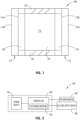
- electro-optic device 100 which generally comprises first substrate 112 having front surface 112A and rear surface 112B, second substrate 114 having front surface 114A and rear surface 114B, and chamber 116 for containing electro-optic medium 124.
- electro-optic device 100 may comprise, for illustrative purposes only, a mirror, a window, a display device, a contrast enhancement filter, and the like.
- FIG. 1 is merely a schematic representation of electro-optic device 100. As such, some of the components have been distorted from their actual scale for pictorial clarity.
- electro-optic medium 124 comprises at least one anodic material, at least one cathodic material, and at least one solvent.
- both the anodic and cathodic materials are electroactive and at least one of them is electrochromic.
- electroactive will be defined herein as a material that undergoes a modification in its oxidation state upon exposure to a particular electrical potential difference.
- electrochromic will be defined herein, regardless of its ordinary meaning, as a material that exhibits a change in its extinction coefficient at one or more wavelengths upon exposure to a particular electrical potential difference.
- Controller system 130 may include a controller 134 in communication with electro-optic device 100.
- Controller 134 may be a programmable controller.
- a power supply 146 may be in communication with controller 134.
- Controller 134 may have one or more pre-loaded executable software routines or algorithms 150 stored thereon, each of which may include instructions for providing a series of pulses of reverse potential to electro-optic device 100, which software routines 150 can be executed by controller 134.
- Controller 134 may be in communication with a potentiometer 138.
- Potentiometer 138 may also be in communication with at least one electrode or at least one layer of electrically conductive material 118, 120 of electro-optic device 100.
- Potentiometer 138 may be disposed at an edge of electro-optic device 100 in proximity to sealing member 122 and in a position in which it can monitor the voltage or open cell potential of electro-optic device 100.
- Controller 134 may selectively provide power to electro-optic device 100. Providing power to electro-optic device 100 may cause the electro-optic device to darken, while providing no power or providing a reverse potential may cause electro-optic device 100 to clear. It should be appreciated by those skilled in the art that a plurality of controllers 134 and/or a plurality of electro-optic devices 100 can be included in controller system 130.
- the clearing of a darkened or partially darkened electro-optic device 100 is a matter of having the color species return to their uncolored form, such that the electrons are transferred to and from colored species to yield their lower energy, uncolored counterparts. This can occur by diffusion alone. However, diffusion is typically slow in larger electro-optic devices, becoming slower with increasing device size.
- Electro-optic device 100 may be symmetrical, in that it can color with either electrode acting as the anode or cathode.
- a reverse potential i.e., opposite of the polarity used to color it
- species are formed at the electrodes that annihilate the existing colored species (e.g., actual meeting of colored species and consequent electron transfer). This increases the speed of clearing; however, a critical point for annihilation can be passed, wherein electro-optic device 100 starts coloring again in response to the reverse potential. This may be referred to as "reverse coloring" and may be considered undesirable.
- Applying PWM to device 100 allows periods of open circuit between the driving pulses.
- the open cell potential of electro-optic device 100 can be measured.
- the open cell potential gives a measure of the state of the electrochemical species at the electrode interfaces. Measuring the open cell potential at the beginning and at the end of an open circuit period may indicate the decay rate of the open cell potential and allow calculation of a diffusion rate of the colored species.
- the decay rate of the open cell potential indicates the strength of the chemical gradient out from the electrode interfaces.
- the decay rate and the open cell potential give a measure of how close to "steady state" (i.e., neither clearing nor darkening) device 100 is.
- Diffusion of the colored species may take place during the second measured time period during which no power is supplied to electro-optic device.
- potentiometer 138 again measures the voltage potential across electro-optic medium 124.
- Controller 134 may compare the potential measured at the beginning of the second measured time period with the potential measured at the end of the second measured time period and determine the difference. Since the rate of decay of potential when power is not being supplied is a function of temperature, the difference in potentials may provide sufficient information to allow the determination of a diffusion gradient which, in turn, may allow the determination of the temperature of device 100. In some cases, one set of measured potentials from the beginning and end of a second measured time period may provide sufficient information for controller 134 to determine a diffusion gradient and use the diffusion gradient to determine a temperature or temperature range.
- a set number of duty cycles may be applied to electro-optic medium 124.
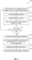
- a reverse bias is provided to a darkened or partially darkened electro-optic device in step 310.
- the potential may be measured at the beginning and end of the second measured time period of each duty cycle as shown in step 320.
- Controller 134 may calculate a potential difference for each duty cycle, and use those to calculate a diffusion gradient and to determine the temperature of electro-optic device 100 as shown in step 330.
- controller 134 may then select one of the pre-loaded executable software routines 150 as shown in step 270 and 340.
- Software routine 150 will be chosen based on the calculated temperature, and the implementation of the selected software routine may result in optimal clearing speed of electro-optic device 100 at its current temperature with minimal or no reverse coloring.
- Software routines 150 when executed by controller 134, may direct controller 134 to provide power or a reverse potential to electro-optic device 100.
- Power or reverse potential may be provided continuously or in pulses such as through PWM signals.
- Each PWM cycle may comprise providing a reverse potential to device 100 for a first measured time interval followed by a second measured time interval during which no power is supplied to device 100, and each software routine 150 may comprise a frequency and duty cycle for a PWM signal. Choosing a software routine 150 with an appropriate frequency and duty cycle for device 100 temperature may optimize clearing speed while avoiding reverse coloring of device 100.
- the duty cycles in software routines 150 may range from 0% to 100%.
- the plurality of software routines 150 may all have the same duty cycles but differ in frequency, or may all have the same frequency, but have different duty cycles, or have both different duty cycles and different frequencies from one another.
- the duty cycles and frequencies in the plurality of software routines 150 which are used to clear device 100 in step 280 may be the same as or different than the duty cycle and frequency used when determining the temperature of electro-optic device 100 in steps 220-260.
- step 280 and 350 the instructions in software routine 150 are executed, and electro-optic device is cleared.
- the method 200 can end at step 290 or 360 when electro-optic device 100 is in a clear state and controller system 130 has been powered off.
- Pulse width modulation may also be beneficial for driving larger electrochromic or electro-optic cells, like electrochromic windows, to intermediate states.
- controllers drive electro-chromic windows to intermediate states through voltage control.
- the steady state transmissance changes rapidly from about 0.3V to about 0.5V. This makes it difficult to reliably hold a transmittance level in that range.
- the transmittance level is so sensitive in that range, it is significantly affected by temperature change.
- IR effects voltage drop across electrically conductive material 118, 120 due to its sheet resistance.
- the part may be pulsed at the maximum (1.2V) drive potential, the effects of IR drop across electrically conductive material 118, 120 are minimized. Because the charging rate of the electro-optic cell is controlled by the duty cycle of the PWM, intermediate transmittance states can be controlled, even in the steepest part of the transition. Lastly, monitoring of the open cell potential decay between pulses allows the diffusion rate of the cell (temperature) to be determined and corrected for in order to hold a particular transmittance level.
- EO device 100 While the temperature of EO device 100 can be directly measured via routes such as a thermocouple or optical pyrometer, in some cases, design constraints may make these approaches undesirable.
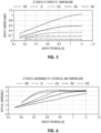
- One alternative approach to determining the temperature of EO device 100 is to determine the steady state current at multiple potentials and temperatures as shown in the example in FIG. 5 .
- reverse bias pulse times optimized for specific device temperature can be utilized to further enhance EO device performance. These times may be represented by, for example, a formula relating the optimum reverse bias time to temperature or a lookup table enabling interpolation based on the nearest listed values.
- the steady state optical absorbance of EO device 100 can be measured at multiple device potentials and temperatures as shown in the example of FIG. 6 .
- the steady state absorbance of the EO device 100 can be based on the potential and current draw at steady state.
- the steady state absorbance can be a function of EO device temperature. This relationship also enables the calculation of temperature corrected potentials for driving EO device 100 to specific intermediate states.
- controller 134 may determine an adjustment factor.
- the adjustment factor may be used to adjust the potential being applied to electro-optic device 100.
- the application of the adjustment factor to the potential to be applied to electro-optic device 100 may overcome any undesirable effect of elevated temperatures on transmissivity levels.
- electro-optic device 100 is an electrochromic window.
Landscapes
- Physics & Mathematics (AREA)
- Nonlinear Science (AREA)
- General Physics & Mathematics (AREA)
- Optics & Photonics (AREA)
- Chemical & Material Sciences (AREA)
- Chemical Kinetics & Catalysis (AREA)
- Electrochromic Elements, Electrophoresis, Or Variable Reflection Or Absorption Elements (AREA)
Claims (5)
- Ein Steuersystem (130), das konfiguriert ist, um eine elektrochrome Vorrichtung zu löschen bzw. zu entfärben (clear), wobei das Steuersystem Folgendes umfasst:eine elektrochrome Vorrichtung (100), die Folgendes umfasst:ein erstes Substrat (112) mit einer ersten Oberfläche (112A), und einer zweiten Oberfläche (112B), auf der eine erste Schicht aus elektrisch leitfähigem Material (118) angeordnet ist;ein zweites Substrat (114) mit einer ersten Oberfläche (114A), auf der eine zweite Schicht aus elektrisch leitendem Material (120) angeordnet ist, und einer zweiten Oberfläche (114B), wobei das zweite Substrat (114) ungefähr parallel zum ersten Substrat (112) ist;ein Dichtungselement (122), das zwischen dem ersten und dem zweiten Substrat (112, 114) verläuft, sodass durch das erste und das zweite Substrat (112, 114) und das Dichtungselement (122) eine Kammer (116) definiert wird; undein elektrooptisches Medium (124), das in der Kammer (116) angeordnet ist, die durch das erste und das zweite Substrat und das Dichtungselement definiert ist, und das in Kontakt mit der ersten und der zweiten Schicht aus elektrisch leitfähigem Material steht;eine Steuerung (134), die mit der elektrochromen Vorrichtung (100) in Verbindung steht; undein Potentiometer (148), das in elektrischer Verbindung mit der elektrochromen Vorrichtung (100) und in Verbindung mit der Steuerung (134) steht;wobei die Steuerung dazu konfiguriert ist, ein oder mehrere Pulsbreitenmodulationssignale zu verwenden, um zu bewirken, dass der elektrochromen Vorrichtung elektrische Energie zugeführt wird;wobei das Potentiometer ein Abklingen des offenen Zellpotentials (open cell potential decay) der elektrochromen Vorrichtung zwischen Impulsen elektrischer Energie überwacht, die durch ein oder mehrere Pulsbreitenmodulationssignale bereitgestellt werden;wobei die Steuerung (134) in der Lage ist, die elektrische Energie, die der elektrochromen Vorrichtung (100) zugeführt wird, in einem oder mehreren Zyklen zu steuern, wobei jeder Zyklus Folgendes umfasst: das Zuführen eines Umkehrpotentials zur elektrochromen Vorrichtung (100) für ein erstes gemessenes Zeitintervall und das Zuführen keiner Energie zur elektrochromen Vorrichtung (100) für ein zweites gemessenes Zeitintervall;wobei die Steuerung (134) dazu in der Lage ist, eine oder mehrere Softwareroutinen auszuführen; wobei jede der einen oder der mehreren Softwareroutinen Anweisungen umfasst, die die Länge des ersten gemessenen Zeitintervalls und des zweiten gemessenen Zeitintervalls detailliert beschreiben; undwobei die Steuerung (134) eine von der einen oder den mehreren Softwareroutinen ausführt, die dazu konfiguriert sind, die elektrochrome Vorrichtung (100) basierend auf einer Temperatur der elektrochromen Vorrichtung (100) mit Strom zu versorgen;dadurch gekennzeichnet, dass:
die Steuerung (134) in der Lage ist, Anweisungen zum Bestimmen einer Temperatur der elektrochromen Vorrichtung (100) ausführt, wobei die Anweisungen Folgendes umfassen: Messen eines ersten offenen Zellpotentials der elektrochromen Flüssigkeit zu Beginn des zweiten gemessenen Zeitintervalls; Messen eines zweiten offenen Zellpotentials der elektrochromen Flüssigkeit am Ende des zweiten gemessenen Zeitintervalls; und Vergleichen des ersten offenen Zellpotentials der elektrochromen Flüssigkeit mit dem zweiten offenen Zellpotential der elektrochromen Flüssigkeit. - Das Steuerungssystem nach Anspruch 1, wobei die Steuerung (134) eine programmierbare Steuerung ist.
- Das Steuerungssystem nach Anspruch 1 oder 2, wobei die Anweisungen den zusätzlichen Schritt umfassen, die Differenz zwischen dem ersten offenen Zellpotential und dem zweiten offenen Zellpotential zu verwenden, um einen Diffusionsgradienten der elektrochromen Flüssigkeit zu bestimmen, und den Diffusionsgradienten zu verwenden, um die Temperatur der elektrochromen Flüssigkeit zu bestimmen.
- Das Steuerungssystem nach einem der vorstehenden Ansprüche, wobei die Steuerung (134) ferner konfiguriert ist, um die Übergänge der elektrochromen Vorrichtung (100) von einem im Wesentlichen dunklen Zustand in einen im Wesentlichen klaren Zustand ohne wesentliche umgekehrte Einfärbung bzw. Rückwärtsfärbung (reverse coloring) steuert.
- Das Steuerungssystem nach einem der vorstehenden Ansprüche, wobei die Steuerung (134) mindestens einen Anweisungssatz zum Löschen der elektrochromen Vorrichtung umfasst, wobei der mindestens eine Anweisungssatz die Schritte des Anlegens eines oder mehrerer Pulsweitenmodulationssignale umfasst, wobei jedes Pulsbreitenmodulationssignal das Anlegen einer Sperrspannung an die elektrochrome Flüssigkeit für ein erstes gemessenes Zeitintervall und das Anlegen keiner Spannung an die elektrochrome Flüssigkeit für eine zweite gemessene Zeitperiode umfasst, und wobei jedes Pulsbreitenmodulationssignal ein Tastverhältnis und eine Frequenz umfasst; und wobei die Steuerung (134) einen Anweisungssatz auf der Grundlage der Temperatur auswählt.
Applications Claiming Priority (2)
| Application Number | Priority Date | Filing Date | Title |
|---|---|---|---|
| US201862725496P | 2018-08-31 | 2018-08-31 | |
| PCT/US2019/048315 WO2020046914A1 (en) | 2018-08-31 | 2019-08-27 | Pulse-width modulation for clearing electro-optic device |
Publications (3)
| Publication Number | Publication Date |
|---|---|
| EP3844566A1 EP3844566A1 (de) | 2021-07-07 |
| EP3844566A4 EP3844566A4 (de) | 2021-10-27 |
| EP3844566B1 true EP3844566B1 (de) | 2025-03-05 |
Family
ID=69639029
Family Applications (1)
| Application Number | Title | Priority Date | Filing Date |
|---|---|---|---|
| EP19855652.4A Active EP3844566B1 (de) | 2018-08-31 | 2019-08-27 | Pulsbreitenmodulation zum löschen einer elektrooptischen vorrichtung |
Country Status (4)
| Country | Link |
|---|---|
| US (1) | US11269231B2 (de) |
| EP (1) | EP3844566B1 (de) |
| CN (1) | CN112789554B (de) |
| WO (1) | WO2020046914A1 (de) |
Families Citing this family (2)
| Publication number | Priority date | Publication date | Assignee | Title |
|---|---|---|---|---|
| WO2021195356A1 (en) * | 2020-03-26 | 2021-09-30 | Gentex Corporation | Voltage control apparatus for electro-optic element |
| DE212023000222U1 (de) * | 2022-04-18 | 2025-01-10 | Gentex Corporation | Hexagonale Packung von elektro-optischen Vorrichtungen mit mehreren Segmenten |
Citations (1)
| Publication number | Priority date | Publication date | Assignee | Title |
|---|---|---|---|---|
| US20060018000A1 (en) * | 2004-07-23 | 2006-01-26 | Greer Bryan D | Control system for electrochromic devices |
Family Cites Families (21)
| Publication number | Priority date | Publication date | Assignee | Title |
|---|---|---|---|---|
| US4810599A (en) * | 1987-03-27 | 1989-03-07 | Japan Synthetic Rubber Co., Ltd. | Structure suitable for solid electrochemical elements |
| US6528782B1 (en) * | 1996-08-20 | 2003-03-04 | Schott Donnelly Llc | Chromogenic light filter and controls |
| DE19748358A1 (de) * | 1997-11-03 | 1999-05-06 | Bayer Ag | Elektrochromes System |
| JPH11204149A (ja) * | 1998-01-13 | 1999-07-30 | Denso Corp | リチウム電池の残存容量測定方法 |
| US6631022B1 (en) * | 1999-05-28 | 2003-10-07 | Sony Corporation | Optical device, a fabrication method thereof, a driving method thereof and a camera system |
| US6856444B2 (en) * | 2002-05-10 | 2005-02-15 | Sage Electrochromics, Inc. | Inferential temperature measurement of an electrochromic device |
| US7375871B2 (en) * | 2004-11-03 | 2008-05-20 | Leviton Manufacturing Co., Inc. | Electrochromic glass control device |
| US7990603B2 (en) * | 2006-06-09 | 2011-08-02 | Gentex Corporation | Variable transmission window system |
| US7646166B2 (en) * | 2006-12-06 | 2010-01-12 | Gm Global Technology Operations, Inc. | Method and apparatus for modeling diffusion in an electrochemical system |
| DE102007014751A1 (de) | 2007-01-24 | 2008-08-07 | Otto Bock Healthcare Products Gmbh | Potentiometer |
| EP2165238A4 (de) * | 2007-06-01 | 2011-04-06 | Chromogenics Ab | Steuerung einer elektrochromen vorrichtung |
| US20130271813A1 (en) * | 2012-04-17 | 2013-10-17 | View, Inc. | Controller for optically-switchable windows |
| EP2652547B1 (de) * | 2010-12-15 | 2019-10-23 | Switch Materials, Inc. | Optischer filter von variabler durchlässigkeit mit einem im wesentlichen co-planaren elektrodensystem |
| US9454055B2 (en) * | 2011-03-16 | 2016-09-27 | View, Inc. | Multipurpose controller for multistate windows |
| JP2013208034A (ja) * | 2012-03-29 | 2013-10-07 | Honda Motor Co Ltd | 開回路電圧推定装置 |
| US9405165B2 (en) | 2012-03-30 | 2016-08-02 | Gentex Corporation | Controller configured for an electro-optic device and method thereof |
| WO2013155612A1 (en) * | 2012-04-18 | 2013-10-24 | Switch Materials Inc. | System and method for controlling an optical filter assembly |
| JP2016218357A (ja) * | 2015-05-25 | 2016-12-22 | 株式会社リコー | エレクトロクロミック素子の駆動方法及びエレクトロクロミック素子 |
| US20170102601A1 (en) * | 2015-10-08 | 2017-04-13 | Gentex Corporation | Window assembly with infrared reflector |
| EP3944013B1 (de) * | 2015-10-09 | 2024-08-21 | View, Inc. | Steuerung der übergänge in optisch schaltbaren vorrichtungen |
| CN106646256B (zh) * | 2016-12-21 | 2020-05-29 | 惠州亿纬创能电池有限公司 | 电池容量计算方法 |
-
2019
- 2019-08-27 EP EP19855652.4A patent/EP3844566B1/de active Active
- 2019-08-27 WO PCT/US2019/048315 patent/WO2020046914A1/en not_active Ceased
- 2019-08-27 US US16/552,494 patent/US11269231B2/en active Active
- 2019-08-27 CN CN201980065504.2A patent/CN112789554B/zh active Active
Patent Citations (1)
| Publication number | Priority date | Publication date | Assignee | Title |
|---|---|---|---|---|
| US20060018000A1 (en) * | 2004-07-23 | 2006-01-26 | Greer Bryan D | Control system for electrochromic devices |
Also Published As
| Publication number | Publication date |
|---|---|
| EP3844566A1 (de) | 2021-07-07 |
| US11269231B2 (en) | 2022-03-08 |
| CN112789554A (zh) | 2021-05-11 |
| EP3844566A4 (de) | 2021-10-27 |
| CN112789554B (zh) | 2024-04-09 |
| WO2020046914A1 (en) | 2020-03-05 |
| US20200073192A1 (en) | 2020-03-05 |
Similar Documents
| Publication | Publication Date | Title |
|---|---|---|
| US6297900B1 (en) | Electrophotochromic smart windows and methods | |
| CN108445661B (zh) | 用于控制滤光器组件的系统和方法 | |
| EP3072011B1 (de) | Verfahren und vorrichtung zur steuerung elektrochromer vorrichtungen | |
| CN101707892A (zh) | 电致变色器件的控制 | |
| US20160041447A1 (en) | Method and apparatus for driving an electrochromic element | |
| JP6696287B2 (ja) | エレクトロクロミック素子の駆動方法及びエレクトロクロミック素子 | |
| WO2016126460A2 (en) | Electrochromic devices | |
| EP3844566B1 (de) | Pulsbreitenmodulation zum löschen einer elektrooptischen vorrichtung | |
| US20200233279A1 (en) | Drive circuit and drive method for driving electrodeposition element | |
| TW201742046A (zh) | 電致變色元件的驅動方法及決定褪色電壓的方法 | |
| US9405165B2 (en) | Controller configured for an electro-optic device and method thereof | |
| JPS6024479B2 (ja) | 表示装置の駆動方式 | |
| CN113156730B (zh) | 控制电致变色器件的方法 | |
| KR102678599B1 (ko) | 가변 광 투과율 장치 및 관련 제어 방법 | |
| JPS59109B2 (ja) | エレクトロクロミック表示装置の駆動回路 | |
| US20200207187A1 (en) | Variable transmittance vehicle window | |
| JPS6131300Y2 (de) | ||
| Wang et al. | A flexible quasi-solid-state electrochromic device with polymeric electrolyte and wo3/nio complementary system | |
| CN113156731B (zh) | 控制电致变色器件的方法 | |
| KR101985803B1 (ko) | 전기변색소자의 제어장치, 이를 포함하는 전기변색 모듈 및 전기변색 소자의 제어방법 | |
| JPS623783Y2 (de) | ||
| CN112835243A (zh) | 电致变色器件 | |
| JPH0136117B2 (de) | ||
| AU8425698A (en) | Electrophotochromic smart windows and methods |
Legal Events
| Date | Code | Title | Description |
|---|---|---|---|
| STAA | Information on the status of an ep patent application or granted ep patent |
Free format text: STATUS: THE INTERNATIONAL PUBLICATION HAS BEEN MADE |
|
| STAA | Information on the status of an ep patent application or granted ep patent |
Free format text: STATUS: REQUEST FOR EXAMINATION WAS MADE |
|
| PUAI | Public reference made under article 153(3) epc to a published international application that has entered the european phase |
Free format text: ORIGINAL CODE: 0009012 |
|
| 17P | Request for examination filed |
Effective date: 20210331 |
|
| AK | Designated contracting states |
Kind code of ref document: A1 Designated state(s): AL AT BE BG CH CY CZ DE DK EE ES FI FR GB GR HR HU IE IS IT LI LT LU LV MC MK MT NL NO PL PT RO RS SE SI SK SM TR |
|
| A4 | Supplementary search report drawn up and despatched |
Effective date: 20210917 |
|
| RIC1 | Information provided on ipc code assigned before grant |
Ipc: G02F 1/163 20060101ALI20210916BHEP Ipc: G02F 1/1503 20190101ALI20210916BHEP Ipc: G02F 1/15 20190101AFI20210916BHEP |
|
| RA4 | Supplementary search report drawn up and despatched (corrected) |
Effective date: 20210922 |
|
| DAV | Request for validation of the european patent (deleted) | ||
| DAX | Request for extension of the european patent (deleted) | ||
| P01 | Opt-out of the competence of the unified patent court (upc) registered |
Effective date: 20230503 |
|
| STAA | Information on the status of an ep patent application or granted ep patent |
Free format text: STATUS: EXAMINATION IS IN PROGRESS |
|
| 17Q | First examination report despatched |
Effective date: 20230629 |
|
| GRAP | Despatch of communication of intention to grant a patent |
Free format text: ORIGINAL CODE: EPIDOSNIGR1 |
|
| STAA | Information on the status of an ep patent application or granted ep patent |
Free format text: STATUS: GRANT OF PATENT IS INTENDED |
|
| INTG | Intention to grant announced |
Effective date: 20241016 |
|
| GRAS | Grant fee paid |
Free format text: ORIGINAL CODE: EPIDOSNIGR3 |
|
| GRAA | (expected) grant |
Free format text: ORIGINAL CODE: 0009210 |
|
| STAA | Information on the status of an ep patent application or granted ep patent |
Free format text: STATUS: THE PATENT HAS BEEN GRANTED |
|
| AK | Designated contracting states |
Kind code of ref document: B1 Designated state(s): AL AT BE BG CH CY CZ DE DK EE ES FI FR GB GR HR HU IE IS IT LI LT LU LV MC MK MT NL NO PL PT RO RS SE SI SK SM TR |
|
| REG | Reference to a national code |
Ref country code: GB Ref legal event code: FG4D |
|
| REG | Reference to a national code |
Ref country code: CH Ref legal event code: EP |
|
| REG | Reference to a national code |
Ref country code: DE Ref legal event code: R096 Ref document number: 602019067004 Country of ref document: DE |
|
| REG | Reference to a national code |
Ref country code: IE Ref legal event code: FG4D |
|
| PG25 | Lapsed in a contracting state [announced via postgrant information from national office to epo] |
Ref country code: RS Free format text: LAPSE BECAUSE OF FAILURE TO SUBMIT A TRANSLATION OF THE DESCRIPTION OR TO PAY THE FEE WITHIN THE PRESCRIBED TIME-LIMIT Effective date: 20250605 |
|
| PG25 | Lapsed in a contracting state [announced via postgrant information from national office to epo] |
Ref country code: FI Free format text: LAPSE BECAUSE OF FAILURE TO SUBMIT A TRANSLATION OF THE DESCRIPTION OR TO PAY THE FEE WITHIN THE PRESCRIBED TIME-LIMIT Effective date: 20250305 |
|
| REG | Reference to a national code |
Ref country code: NL Ref legal event code: MP Effective date: 20250305 |
|
| PG25 | Lapsed in a contracting state [announced via postgrant information from national office to epo] |
Ref country code: ES Free format text: LAPSE BECAUSE OF FAILURE TO SUBMIT A TRANSLATION OF THE DESCRIPTION OR TO PAY THE FEE WITHIN THE PRESCRIBED TIME-LIMIT Effective date: 20250305 |
|
| REG | Reference to a national code |
Ref country code: LT Ref legal event code: MG9D |
|
| PG25 | Lapsed in a contracting state [announced via postgrant information from national office to epo] |
Ref country code: NO Free format text: LAPSE BECAUSE OF FAILURE TO SUBMIT A TRANSLATION OF THE DESCRIPTION OR TO PAY THE FEE WITHIN THE PRESCRIBED TIME-LIMIT Effective date: 20250605 |
|
| PG25 | Lapsed in a contracting state [announced via postgrant information from national office to epo] |
Ref country code: HR Free format text: LAPSE BECAUSE OF FAILURE TO SUBMIT A TRANSLATION OF THE DESCRIPTION OR TO PAY THE FEE WITHIN THE PRESCRIBED TIME-LIMIT Effective date: 20250305 |
|
| PG25 | Lapsed in a contracting state [announced via postgrant information from national office to epo] |
Ref country code: LV Free format text: LAPSE BECAUSE OF FAILURE TO SUBMIT A TRANSLATION OF THE DESCRIPTION OR TO PAY THE FEE WITHIN THE PRESCRIBED TIME-LIMIT Effective date: 20250305 |
|
| PG25 | Lapsed in a contracting state [announced via postgrant information from national office to epo] |
Ref country code: GR Free format text: LAPSE BECAUSE OF FAILURE TO SUBMIT A TRANSLATION OF THE DESCRIPTION OR TO PAY THE FEE WITHIN THE PRESCRIBED TIME-LIMIT Effective date: 20250606 Ref country code: BG Free format text: LAPSE BECAUSE OF FAILURE TO SUBMIT A TRANSLATION OF THE DESCRIPTION OR TO PAY THE FEE WITHIN THE PRESCRIBED TIME-LIMIT Effective date: 20250305 |
|
| REG | Reference to a national code |
Ref country code: AT Ref legal event code: MK05 Ref document number: 1773440 Country of ref document: AT Kind code of ref document: T Effective date: 20250305 |
|
| PG25 | Lapsed in a contracting state [announced via postgrant information from national office to epo] |
Ref country code: NL Free format text: LAPSE BECAUSE OF FAILURE TO SUBMIT A TRANSLATION OF THE DESCRIPTION OR TO PAY THE FEE WITHIN THE PRESCRIBED TIME-LIMIT Effective date: 20250305 |
|
| PG25 | Lapsed in a contracting state [announced via postgrant information from national office to epo] |
Ref country code: SE Free format text: LAPSE BECAUSE OF FAILURE TO SUBMIT A TRANSLATION OF THE DESCRIPTION OR TO PAY THE FEE WITHIN THE PRESCRIBED TIME-LIMIT Effective date: 20250305 |
|
| PG25 | Lapsed in a contracting state [announced via postgrant information from national office to epo] |
Ref country code: SM Free format text: LAPSE BECAUSE OF FAILURE TO SUBMIT A TRANSLATION OF THE DESCRIPTION OR TO PAY THE FEE WITHIN THE PRESCRIBED TIME-LIMIT Effective date: 20250305 |
|
| PG25 | Lapsed in a contracting state [announced via postgrant information from national office to epo] |
Ref country code: PT Free format text: LAPSE BECAUSE OF FAILURE TO SUBMIT A TRANSLATION OF THE DESCRIPTION OR TO PAY THE FEE WITHIN THE PRESCRIBED TIME-LIMIT Effective date: 20250707 |
|
| PGFP | Annual fee paid to national office [announced via postgrant information from national office to epo] |
Ref country code: DE Payment date: 20250724 Year of fee payment: 7 |
|
| PG25 | Lapsed in a contracting state [announced via postgrant information from national office to epo] |
Ref country code: IT Free format text: LAPSE BECAUSE OF FAILURE TO SUBMIT A TRANSLATION OF THE DESCRIPTION OR TO PAY THE FEE WITHIN THE PRESCRIBED TIME-LIMIT Effective date: 20250305 Ref country code: PL Free format text: LAPSE BECAUSE OF FAILURE TO SUBMIT A TRANSLATION OF THE DESCRIPTION OR TO PAY THE FEE WITHIN THE PRESCRIBED TIME-LIMIT Effective date: 20250305 |
|
| PGFP | Annual fee paid to national office [announced via postgrant information from national office to epo] |
Ref country code: GB Payment date: 20250725 Year of fee payment: 7 |
|
| PG25 | Lapsed in a contracting state [announced via postgrant information from national office to epo] |
Ref country code: AT Free format text: LAPSE BECAUSE OF FAILURE TO SUBMIT A TRANSLATION OF THE DESCRIPTION OR TO PAY THE FEE WITHIN THE PRESCRIBED TIME-LIMIT Effective date: 20250305 |
|
| PGFP | Annual fee paid to national office [announced via postgrant information from national office to epo] |
Ref country code: FR Payment date: 20250725 Year of fee payment: 7 |
|
| PG25 | Lapsed in a contracting state [announced via postgrant information from national office to epo] |
Ref country code: CZ Free format text: LAPSE BECAUSE OF FAILURE TO SUBMIT A TRANSLATION OF THE DESCRIPTION OR TO PAY THE FEE WITHIN THE PRESCRIBED TIME-LIMIT Effective date: 20250305 Ref country code: EE Free format text: LAPSE BECAUSE OF FAILURE TO SUBMIT A TRANSLATION OF THE DESCRIPTION OR TO PAY THE FEE WITHIN THE PRESCRIBED TIME-LIMIT Effective date: 20250305 |
|
| PG25 | Lapsed in a contracting state [announced via postgrant information from national office to epo] |
Ref country code: RO Free format text: LAPSE BECAUSE OF FAILURE TO SUBMIT A TRANSLATION OF THE DESCRIPTION OR TO PAY THE FEE WITHIN THE PRESCRIBED TIME-LIMIT Effective date: 20250305 |
|
| PG25 | Lapsed in a contracting state [announced via postgrant information from national office to epo] |
Ref country code: SK Free format text: LAPSE BECAUSE OF FAILURE TO SUBMIT A TRANSLATION OF THE DESCRIPTION OR TO PAY THE FEE WITHIN THE PRESCRIBED TIME-LIMIT Effective date: 20250305 |
|
| PG25 | Lapsed in a contracting state [announced via postgrant information from national office to epo] |
Ref country code: IS Free format text: LAPSE BECAUSE OF FAILURE TO SUBMIT A TRANSLATION OF THE DESCRIPTION OR TO PAY THE FEE WITHIN THE PRESCRIBED TIME-LIMIT Effective date: 20250705 |
|
| REG | Reference to a national code |
Ref country code: DE Ref legal event code: R097 Ref document number: 602019067004 Country of ref document: DE |
|
| PLBE | No opposition filed within time limit |
Free format text: ORIGINAL CODE: 0009261 |
|
| STAA | Information on the status of an ep patent application or granted ep patent |
Free format text: STATUS: NO OPPOSITION FILED WITHIN TIME LIMIT |
|
| PG25 | Lapsed in a contracting state [announced via postgrant information from national office to epo] |
Ref country code: DK Free format text: LAPSE BECAUSE OF FAILURE TO SUBMIT A TRANSLATION OF THE DESCRIPTION OR TO PAY THE FEE WITHIN THE PRESCRIBED TIME-LIMIT Effective date: 20250305 |
|
| REG | Reference to a national code |
Ref country code: CH Ref legal event code: L10 Free format text: ST27 STATUS EVENT CODE: U-0-0-L10-L00 (AS PROVIDED BY THE NATIONAL OFFICE) Effective date: 20260114 |
|
| 26N | No opposition filed |
Effective date: 20251208 |
|
| REG | Reference to a national code |
Ref country code: CH Ref legal event code: H13 Free format text: ST27 STATUS EVENT CODE: U-0-0-H10-H13 (AS PROVIDED BY THE NATIONAL OFFICE) Effective date: 20260324 |
|
| PG25 | Lapsed in a contracting state [announced via postgrant information from national office to epo] |
Ref country code: MC Free format text: LAPSE BECAUSE OF FAILURE TO SUBMIT A TRANSLATION OF THE DESCRIPTION OR TO PAY THE FEE WITHIN THE PRESCRIBED TIME-LIMIT Effective date: 20250305 |
|
| PG25 | Lapsed in a contracting state [announced via postgrant information from national office to epo] |
Ref country code: LU Free format text: LAPSE BECAUSE OF NON-PAYMENT OF DUE FEES Effective date: 20250827 |
|
| PG25 | Lapsed in a contracting state [announced via postgrant information from national office to epo] |
Ref country code: CH Free format text: LAPSE BECAUSE OF NON-PAYMENT OF DUE FEES Effective date: 20250831 |