EP3843293B1 - Signalsendevorrichtung und -system - Google Patents
Signalsendevorrichtung und -system Download PDFInfo
- Publication number
- EP3843293B1 EP3843293B1 EP20203998.8A EP20203998A EP3843293B1 EP 3843293 B1 EP3843293 B1 EP 3843293B1 EP 20203998 A EP20203998 A EP 20203998A EP 3843293 B1 EP3843293 B1 EP 3843293B1
- Authority
- EP
- European Patent Office
- Prior art keywords
- signal
- optical channel
- rate
- physical link
- signals
- Prior art date
- Legal status (The legal status is an assumption and is not a legal conclusion. Google has not performed a legal analysis and makes no representation as to the accuracy of the status listed.)
- Active
Links
Images


Classifications
-
- H—ELECTRICITY
- H04—ELECTRIC COMMUNICATION TECHNIQUE
- H04B—TRANSMISSION
- H04B10/00—Transmission systems employing electromagnetic waves other than radio-waves, e.g. infrared, visible or ultraviolet light, or employing corpuscular radiation, e.g. quantum communication
- H04B10/50—Transmitters
- H04B10/516—Details of coding or modulation
- H04B10/532—Polarisation modulation
-
- H—ELECTRICITY
- H04—ELECTRIC COMMUNICATION TECHNIQUE
- H04B—TRANSMISSION
- H04B10/00—Transmission systems employing electromagnetic waves other than radio-waves, e.g. infrared, visible or ultraviolet light, or employing corpuscular radiation, e.g. quantum communication
- H04B10/60—Receivers
-
- H—ELECTRICITY
- H04—ELECTRIC COMMUNICATION TECHNIQUE
- H04J—MULTIPLEX COMMUNICATION
- H04J3/00—Time-division multiplex systems
- H04J3/16—Time-division multiplex systems in which the time allocation to individual channels within a transmission cycle is variable, e.g. to accommodate varying complexity of signals, to vary number of channels transmitted
- H04J3/1605—Fixed allocated frame structures
- H04J3/1652—Optical Transport Network [OTN]
- H04J3/1658—Optical Transport Network [OTN] carrying packets or ATM cells
-
- H—ELECTRICITY
- H04—ELECTRIC COMMUNICATION TECHNIQUE
- H04L—TRANSMISSION OF DIGITAL INFORMATION, e.g. TELEGRAPHIC COMMUNICATION
- H04L47/00—Traffic control in data switching networks
- H04L47/10—Flow control; Congestion control
- H04L47/34—Flow control; Congestion control ensuring sequence integrity, e.g. using sequence numbers
-
- H—ELECTRICITY
- H04—ELECTRIC COMMUNICATION TECHNIQUE
- H04L—TRANSMISSION OF DIGITAL INFORMATION, e.g. TELEGRAPHIC COMMUNICATION
- H04L12/00—Data switching networks
- H04L12/28—Data switching networks characterised by path configuration, e.g. LAN [Local Area Networks] or WAN [Wide Area Networks]
- H04L12/2854—Wide area networks, e.g. public data networks
- H04L12/2856—Access arrangements, e.g. Internet access
- H04L12/2869—Operational details of access network equipments
- H04L12/2878—Access multiplexer, e.g. DSLAM
- H04L12/2879—Access multiplexer, e.g. DSLAM characterised by the network type on the uplink side, i.e. towards the service provider network
- H04L12/2885—Arrangements interfacing with optical systems
Definitions
- the present invention relates to the field of optical communications technologies, and in particular, to a signal sending and receiving method, an apparatus, and a system.
- An optical transport network (OTN, Optical Transport Network) is a core technology of a transport network.
- OTN has rich operation administration and maintenance (OAM, Operation Administration and Maintenance) capabilities, a strong tandem connection monitoring (TCM, Tandem Connection Monitoring) capability, and an out-of-band forward error correction (FEC, Forward Error Correction) capability, and can implement flexible scheduling and management of large-capacity services.
- OAM Operation Administration and Maintenance
- TCM Tandem Connection Monitoring
- FEC Forward Error Correction
- the OTN standardization system defines four optical channel transport units (OTU, Optical channel Transport Unit) of fixed line rates: an OTU1, an OTU2, an OTU3, and an OTU4, whose line rate levels are respectively 2.5 Gbit/s, 10 Gbit/s, 40 Gbit/s, and 100 Gbit/s, that is, gigabits per second.
- the four OTUs respectively correspond to four optical channel data units (ODU, Optical channel Data Unit) of same rate levels: an ODU1, an ODU2, an ODU3, and an ODU4.
- the four ODUs respectively correspond to four optical channel payload units (OPU, Optical channel Payload Unit) of same rate levels: an OPU1, an OPU2, an OPU3, and an OPU4.
- an OTUCn (where C is a roman numeral for 100, and n is a positive integer) interface for beyond-100G OTN applications.
- the OTUCn interface can provide an electrical interface processing capability of an n* 100 G rate.
- An OTUCn frame includes n OTU subframes. The OTUCn frame is managed and monitored as one signal, and provides a network management function at an optical channel transport unit level. Correspondingly, there are an ODUCn and an OPUCn of a rate of n* 100 G.
- An ODUCn overhead is added to an OPUCn frame to form an ODUCn frame, and a frame alignment (FA, Frame Aligement Signal) overhead and an OTUCn overhead are added to the ODUCn frame to form an OTUCn frame.
- FA Frame Aligement Signal
- OTUCn overhead is added to the ODUCn frame to form an OTUCn frame.
- the OTUCn frame is modulated by an optical module matching a rate corresponding to the OTUCn frame
- a serial OTUCn bit data flow is formed, and the serial OTUCn bit data flow is sent by using one way of optical fiber.
- the ODUCn needs to be mapped to an OTUCn having a same rate as the ODUCn, and the OTUCn can be sent only after being modulated by an optical module at a same rate as the OTUCn. Therefore, to send ODUCns of different rates, optical modules of different rates need to be used to perform modulation. Further, in the prior art, to send optical channel unit signals of different rates, optical modules of different rates need to be used to perform modulation. This results in high network costs.
- EP 2884687 A1 discloses a method and device for mapping data in an optical transport network.
- the method includes: packet service data is mapped to a Super Optical Channel Data Unit (ODUS) and the ODUS is mapped to a Super Optical Channel Transport Unit (OTUS); and the OTUS is mapped to a Super Optical Channel (OChS).
- ODUS Super Optical Channel Data Unit
- OTUS Super Optical Channel Transport Unit
- OhS Super Optical Channel
- US2013/259478 A1 provides an optical transmitter including: a demultiplexer configured to divide a data frame of a transmission signal into subframes with a predetermined length so as to form the subframes in a plurality of signal lanes; an index generator configured to generate an index for indicating an order of the signal lanes; a lane rearrangement unit configured to rearrange the order of the signal lanes according to the index; a carrier controller configured to generate a frequency offset of a carried corresponding to the index; a mapping unit configured to map the transmission signal in the plurality of signal lanes with the rearranged order to the transmission signal with a phase corresponding to the frequency offset; and a transmitting unit configured to optically module the mapped transmission signal so as to transmit the modulated transmission signal.
- EP 2874332 A1 provides a method and an apparatus for transmitting and receiving a client signal in an optical transport network.
- the method includes: mapping a received client signal into a variable-rate container OTU-N, where a rate of the OTU-N is N times as high as a preset reference rate level, and the value N is a configurable positive integer; splitting the variable-rate container OTU-N into N optical subchannel transport units OTUsubs by column, where a rate of each OTUsub is equal to the reference rate level; modulating the N optical sub-channel transport units OTUsubs onto one or more optical carriers; and sending the one or more optical carriers onto a same fiber for transmission.
- Embodiments of the present invention provide a signal sending and receiving method, an apparatus, and a system, so as to resolve a problem of high network costs due to a need to use optical modules of different rates to perform modulation when optical channel unit signals of different rates are sent.
- an embodiment of the present invention provides a signal sending method, where the method includes:
- mapping a to-be-transmitted optical channel unit signal of n times a benchmark rate to X first optical channel physical link signals includes:
- the signal sending method before the modulating and sending the X second optical channel physical link signals by using X preset optical modules in a one-to-one correspondence manner, the signal sending method further includes: performing forward error correction FEC encoding processing on the X second optical channel physical link signals.
- each of the X first optical channel physical link signals has a different m i ; or any j of the X first optical channel physical link signals have a same m i , where 2 ⁇ j ⁇ X.
- the optical channel unit signal of n times the benchmark rate is an optical channel data unit ODUKn signal of n times the benchmark rate
- the first optical channel physical link signal is a first optical channel transport unit OTUKm; signal.
- an embodiment of the present invention provides a signal receiving method, where the method includes:
- the demapping the X first optical channel physical link signals, to obtain an optical channel unit signal of n times the benchmark rate includes:
- the method before the separately extracting a link sequence indicator overhead of each of the X second optical channel physical link signals, to obtain X first optical channel physical link signals, the method further includes: performing forward error correction FEC decoding on the X second optical channel physical link signals.
- each of the X second optical channel physical link signals has a different m i ; or any j of the X second optical channel physical link signals have a same m i , where 2 ⁇ j ⁇ X.
- the optical channel unit signal of n times the benchmark rate is an optical channel data unit ODUKn signal of n times the benchmark rate.
- an embodiment of the present invention provides a transmitter, including:
- the transmitter further includes a grouping unit, where
- the transmitter further includes an encoding unit, where the encoding unit is configured to: before the modulation unit modulates the X second optical channel physical link signals by using the X preset optical modules in the one-to-one correspondence manner, perform forward error correction FEC encoding processing on the X second optical channel physical link signals generated by the overhead addition unit.
- each of the X first optical channel physical link signals of m; times the benchmark rate has a different m i ; or any j of the X first optical channel physical link signals of m i times the benchmark rate have a same m i , where 2 ⁇ j ⁇ X.
- the optical channel unit signal of n times the benchmark rate is an optical channel data unit ODUKn signal of n times the benchmark rate
- the first optical channel physical link signal is a first optical channel transport unit OTUKm; signal.
- an embodiment of the present invention provides a receiver, including:
- the demapping unit is specifically configured to demap the X first optical channel physical link signals in a preset demapping manner, to obtain X groups of optical channel unit signals, where the preset demapping manner is bit synchronous demapping or asynchronous demapping, and a rate of each group of optical channel unit signals is m; times the benchmark rate; and
- the receiver further includes a decoding unit, where the decoding unit is configured to: before the extraction unit separately extracts the link sequence indicator overhead of each of the X second optical channel physical link signals, to obtain the X first optical channel physical link signals, perform forward error correction FEC decoding on the X second optical channel physical link signals received by the receiving unit.
- each of the X second optical channel physical link signals has a different m i ; or any j of the X second optical channel physical link signals have a same m i , where 2 ⁇ j ⁇ X.
- the optical channel unit signal of n times the benchmark rate is an optical channel data unit ODUKn signal of n times the benchmark rate.
- an embodiment of the present invention provides a signal transmission system, including the transmitter described above and the receiver described above.
- an optical channel unit signal of n times a benchmark rate is no longer mapped to a first optical channel physical link signal of a same rate as the optical channel unit signal, but is mapped to X first optical channel physical link signals of m; times the benchmark rate.
- X existing low-rate optical modules can be used to modulate X signals, and an optical module that matches a rate corresponding to an optical channel unit signal is no longer used for modulation, thereby reducing network costs when optical channel units of different rates need to use optical modules of different rates to perform modulation.
- the ITU-T Standardization Sector is formulating an OTUCn interface for beyond-100 G OTN applications.
- the OTUCn interface can provide an electrical interface processing capability of a rate of n* 100 G.
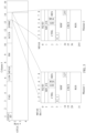
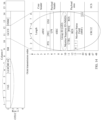
- an OTUCn frame includes n OTU subframes (in FIG. 1 , #n is used to indicate the n th OTU subframe), each OTU subframe has four rows and 3824 columns, an FA OH is a frame alignment overhead byte, used to provide a frame synchronization alignment function, and an OTU OH is an OTUCn overhead byte.
- the FA OH is divided into two parts: a frame alignment signal (FAS, Frame Alignment Signal) and a multiframe alignment signal (MFAS, Multiframe Alignment Signal).
- the FA OH includes seven bytes in total from the first row and the first column to the first row and the seventh column.
- the FAS is located in the first row and the first column to the first row and the sixth column.
- the MFAS is located in the first row and the seventh column.
- the OTU OH includes seven bytes in total from the first row and the eighth column to the first row and the fourteenth column.
- the OTU OH includes three parts: section monitoring (SM, Section Monitoring), a general communications channel (GCC, General Communications Channel), and Reserved for Future International Standardization (RES, Reserved for Future International Standardization).
- SM Section Monitoring
- GCC General Communications Channel
- RES Reserved for Future International Standardization
- the RES is a reserved position, and is currently stipulated to be all 0s.
- the SM is section overhead monitoring.
- SM overhead information includes at least a trail trace identifier (TTI, Trail Trace Identifier), a bit interleaved parity (BIP-8, Bit Interleaved Parity), a backward defect indication (BDI, Backward Defect Indication), and a backward error indication (BEI/BIAE, Backward Error Indication and Backward Incoming Alignment Error).
- TTI Trail Trace Identifier
- BIP-8 Bit Interleaved Parity
- BDI Backward Defect Indication
- BEI/BIAE Backward Error Indication and Backward Incoming Alignment Error
- the OTUCn frame is used managed and monitored as one signal, provides a network management function at an optical channel transport unit level, and mainly carries an OTUCn overhead at a position of an OTU OH of the first OTU subframe.
- a frame structure of the ODUCn may be considered to include n ODU subframes (in FIG. 1 , #n is used to indicate the n th ODU subframe), and each ODU subframe has four rows and 3824 columns.
- a frame alignment overhead FA and an OTUCn overhead are added to an ODUCn frame to form an OTUCn frame.
- the OTUCn frame is modulated by an optical module matching a rate corresponding to the OTUCn frame, a serial OTUCn bit data flow is formed, and the serial OTUCn bit data flow is sent by using one way of optical fiber.
- the OTUCn interface provides an electrical interface capability of a multi-rate level of n*100 G, actually, because of diversity of the rate of the electrical interface, various types of optical modules matching the rate corresponding to the electrical interface are required. This greatly increases network costs. In actual networking, it is impossible to have so many optical modules of different rate types that can be used.
- the ODUCn needs to be mapped to an OTUCn of a same rate, and the OTUCn needs to be first modulated by an optical module matching a rate corresponding to the OTUCn, and then can be sent. Therefore, to send ODUCns of different rates, optical modules of different rates need to be used.
- a transmitter encapsulates, by means of bit synchronization, an ODUC4 of 400 G in an OTUC4, and adds an OTUC4 overhead to form an optical transport unit OTUC4. Subsequently, the transmitter modulates, by using an optical module of 400 G, the OTUC4 onto a single-carrier or multiple-carriers, and sends the OTUC4 by using a same optical fiber.
- the embodiments of the present invention provide signal sending and receiving methods, an apparatus, and a system. Multiple low-rate optical modules are used to implement transmission of an OTN signal of a higher rate.
- FIG. 2 shows a transfer device according to an embodiment of the present invention.
- the transfer device includes a transceiver 30 and a processor 31.
- the processor 31 may be a single-core or multi-core central processing unit, or an application-specific integrated circuit, or one or more integrated circuits configured to implement this embodiment of the present invention.
- the processor 31 includes a framing processing module 310, an ODSP (Optical Digital Signal Processor, optical digital signal processor) chip 311, and an optical module 312.
- the ODSP chip 311 may be an independent function module, or may be integrated into the optical module 312.
- the framing processing module 310 may be a chip for implementing data framing.
- the framing processing module 310 may map to and encapsulate in X first optical channel physical link signals a to-be-transmitted optical channel unit signal of n times a benchmark rate, and adds a link sequence indicator overhead, to form X second optical channel physical link signals.
- the framing processing module 310 may further demap the received X second optical channel physical link signals to obtain the optical channel unit signal of n times the benchmark rate.
- the ODSP chip 311 is configured to complete modulation and demodulation processing of a signal, and is configured to enhance a link error code tolerance capability, or perform other related processing.
- the optical module 312 is configured to complete optical-to-electrical conversion. Specifically, before the X second optical channel physical link signals are sent, the optical module 312 may convert an electrical signal into an optical signal, and may convert the optical signal into an electrical signal after receiving the X second optical channel physical link signals.
- This embodiment of the present invention provides a signal sending method. As shown in FIG. 3 , the method includes the following steps.
- a transmitter maps a to-be-transmitted optical channel unit signal of n times a benchmark rate to X first optical channel physical link signals.
- the transmitter adds a link sequence indicator overhead to each of the X first optical channel physical link signals, to generate X second optical channel physical link signals.
- the link sequence indicator overhead of each first optical channel physical link signal is used to indicate an order of the first optical channel physical link signal, and a rate of the second optical channel physical link signal is m; times the benchmark rate.
- the transmitter modulates and sends the X second optical channel physical link signals by using X preset optical modules in a one-to-one correspondence manner.
- the benchmark rate in the present invention is 100 G, or 40 G.
- the optical channel unit signal of n times the benchmark rate is an optical channel data unit ODUKn signal of n times the benchmark rate
- the first optical channel physical link signal of m times the benchmark rate is a first optical channel transport unit OTUKm i signal of m; times the benchmark rate.
- K is a level of an ODU or a level of an OTU, K is a positive integer, and a value of K is not specifically limited in this embodiment of the present invention.
- the ODUKn signal is an optical channel data unit ODUCn signal of a rate of n* 100 G
- the OTUKm i signal is an optical channel transport unit OTUCm; signal of a rate of m i *100 G, where C is a roman numeral for 100, and n and m; are both positive integers.
- the optical channel unit signal of n times the benchmark rate is an optical channel payload unit OPUKn signal of n times the benchmark rate
- the first optical channel physical link signal of m; times the benchmark rate is a first optical channel transport unit OTUKm i signal of m; times the benchmark rate.
- K is a level of an OPU or a level of an OTU
- K is a positive integer
- a value of K is not specifically limited in this embodiment of the present invention.
- the OPUKn signal is an optical channel payload unit OPUCn signal of a rate of n*100 G
- the OTUKm i signal is an optical channel transport unit OTUCm; signal of a rate of m i *100 G, where C is a roman numeral for 100, and n and m i are both positive integers.
- the optical channel unit signal of n times the benchmark rate is an optical channel transport unit OTUKn signal of n times the benchmark rate
- the first optical channel physical link signal of m i times the benchmark rate is an FEC frame whose payload area is an OTUKm i of m i times the benchmark rate.
- K is a level of an OTU
- K is a positive integer
- a value of K is not specifically limited in this embodiment of the present invention.
- the OTUKm i signal is an optical channel transport unit OTUCm; signal of a rate of m i *100 G, and the OTUKn signal is an OTUCn signal of a rate of n*100 G, where C is a roman numeral for 100, and n and m i are both positive integers.
- a transmitter maps a to-be-transmitted optical channel unit signal of n times a benchmark rate to X first optical channel physical link signals.
- the method for mapping, by the transmitter, the to-be-transmitted optical channel unit signal to the X first optical channel physical link signals is: dividing, by the transmitter, the to-be-transmitted optical channel unit signal of n times the benchmark rate into X preset groups; and mapping, by the transmitter, the X groups of optical channel unit signals to the X first optical channel physical link signals in a preset mapping manner.
- the method for dividing, by the transmitter, the to-be-transmitted optical channel unit signal of n times the benchmark rate into X preset groups is: dividing, by the transmitter, n optical channel unit subframes in a frame structure of the to-be-transmitted optical channel unit signal of n times the benchmark rate into X preset groups.
- the transmitter divides the n optical channel unit subframes into X groups according to a quantity of the preset optical modules and a bearer rate of the preset optical modules.
- the preset mapping manner in this embodiment of the present invention is bit synchronous mapping or asynchronous mapping.
- the transmitter maps, in the preset mapping manner, m; optical channel unit subframes in a frame structure of the p th group of optical channel unit subframe signals to m i first optical channel physical link subframes in a frame structure of the p th first optical channel physical link signal, where X ⁇ p ⁇ 1.
- the frame structure of the p th group of optical channel unit subframe signals includes only one optical channel unit subframe
- the frame structure of the p th first optical channel physical link signal includes only one first optical channel physical link subframe.
- the transmitter directly maps the one optical channel unit subframe to the first optical channel physical link subframe in the frame structure of the first optical channel physical link signal.
- the preset mapping manner in this embodiment of the present invention is bit synchronous mapping.
- the bit synchronous mapping manner in this embodiment of the present invention is a bit synchronous mapping procedure (BMP, Bit Synchronous Mapping Procedure).
- the preset mapping manner in this embodiment of the present invention may be an asynchronous mapping manner. It should be noted that if the transmitter uses the asynchronous mapping manner, corresponding overhead information is generated in an asynchronous mapping process.
- the asynchronous mapping manner in this embodiment of the present invention is a generic mapping procedure (GMP, Generic Mapping Procedure), and overhead information generated in the asynchronous mapping process is Cnd and Cm.
- GMP Generic Mapping Procedure
- Cnd and Cm overhead information generated in the asynchronous mapping process.
- Cnd and Cm refer to the G.709 protocol.
- a ratio of mapping granularities used by the groups of optical channel unit subframe signals is the same as a ratio of quantities of optical channel unit subframes included by the groups of optical channel unit subframe signals.
- the method for mapping, by the transmitter, the to-be-transmitted optical channel unit signal to the X first optical channel physical link signals is: mapping, by the transmitter, the to-be-transmitted optical channel unit signal to an optical channel physical link signal of a same rate as the to-be-transmitted optical channel unit signal; and dividing, by the transmitter, the optical channel physical link signal of a same rate as the optical channel unit signal into X preset groups.
- m i of all the X second optical channel physical link signals may be the same, may be different, or may be partially the same. That is, any j of the X second optical channel physical link signals of m; times the benchmark rate have a same m i , where 2 ⁇ j ⁇ X.
- the transmitter adds a link sequence indicator overhead to each of the X first optical channel physical link signals, to generate X second optical channel physical link signals.
- the link sequence indicator overhead of each first optical channel physical link signal is used to indicate an order of the first optical channel physical link signal. That is, the link sequence indicator overhead of each first optical channel physical link signal is used to indicate a sequence number of the current first optical channel physical link signal in the X first optical channel physical link signals.
- the transmitter first performs link sequence numbering processing on the X first optical channel physical link signals. Then, the transmitter respectively and synchronously adds link sequence numbers of the X signals to the link sequence indicator overheads of all the X first optical channel physical link signals.
- the transmitter adds the link sequence indicator overhead to an overhead range of the frame structure of each first optical channel physical link signal; or the transmitter adds the link sequence indicator overhead to a frame header of the frame structure of each first optical channel physical link signal.
- the transmitter adds the link sequence indicator overhead to an overhead range of a frame structure of each first optical channel transport unit OTUKm i signal. If the first optical channel physical link signal is a signal whose payload area of an FEC frame is an OTUKm i of m; times the benchmark rate, the transmitter adds the link sequence indicator overhead to the frame header of the frame structure of each first optical channel physical link signal.
- the transmitter may further add an extended multiframe indicator overhead and a link group indicator overhead to each of the X first optical channel physical link signals.
- the extended multiframe indicator overhead is used to indicate a transmission delay
- the link group indicator overhead is used to indicate whether the X first optical channel physical link signals have a same source.
- a receiver can determine, according to the link group indicator overhead, whether the X first optical channel physical link signals are sent by a same transmitter.
- the transmitter further adds first overhead information to each of the X first optical channel physical link signals.
- the first overhead information is used to indicate link bandwidth adjustment of the X first optical channel physical link signals, and the first overhead information includes at least a link bandwidth adjustment request, a link bandwidth adjustment response, and a link member status indication. If a link bandwidth of the X first optical channel physical link signals does not meet a requirement, the link bandwidth of the X first optical channel physical link signals may be adjusted according to the first overhead information.
- the frame structure of the first OTUKm i signal includes m; OTUKm i subframes.
- the transmitter further adds a subframe sequence indicator overhead (OTUK ID, OTUK Identifier) to each of X first OTUKm i signals, where the OTUK ID is used to indicate an order of m i OTU subframes in each first OTUKm i signal.
- an OTUK ID and a link sequence indicator overhead of each first optical channel transport unit OTUK1 signal both indicate an order of the first optical channel transport unit OTUK1 signal in the X first OTUKm i signals. Therefore, the OTUK ID may substitute for the link sequence indicator overhead.
- the transmitter performs overall numbering on all the X OTUK1 signals as 1, 2, ..., and X, and respectively and synchronously adds the X numbers to link sequence indicator overheads of all the X OTUK1 signals, but no longer adds any OTUK ID.
- the transmitter further separately generates and adds link segment monitoring overhead information SM to each of the X second optical channel transport unit OTUKm i signals.
- the transmitter adds a frame header indication overhead FAS to each of the X second optical channel transport unit OTUKm i signals. That is, a pattern 0xf6f62828 is added to the first row and the second to the fifth columns of each OTU subframe. For specific information of the pattern 0xf6f62828, refer to the existing protocol.
- the transmitter further adds a logical lane marker (LLM, Logical Lane Marker) to each of the X second optical channel transport unit OTUKm i signals.
- LLMs are used as markers for multiple logical channels. LLMs of all subframes in the frame structure of each second optical channel transport unit OTUKm i signal are the same. An initial value of an LLM is 0, values of all LLMs are in ascending order, and a value range of the LLM is 0 to 239.
- the transmitter After adding a link sequence indicator overhead to each OTUCmi, the transmitter generates a second OTUCm i signal.
- the link sequence indicator overhead (SQ ID, Sequence Identifier) in the frame structure of the second OTUCm i signal is located in the first row and the 14 th column of the first OTU subframe of the OTUCm i .
- the SQ ID is indicated in a multiframe manner. Specifically, the SQ ID is indicated by 32-frame multiframe. When the multiframe indicates that bits 3-7 of an MFAS are 0s, a value at the position is the link sequence indicator overhead.
- the SQ ID is indicated by 256-frame multiframe. When bits 0-7 of an MFAS are 0s, a value at the position is the link sequence indicator overhead.
- An extended multiframe indicator overhead (MFI_EX, Extended Multi-frame Identifier) is located in the first row and the 14 th column of the OTU subframe of the OTUCm i , and is used to indicate a transmission delay.
- the MFI_EX is indicated in a multiframe manner. Manner 1: Specifically, the MFI_EX is indicated by 32-frame multiframe. When the multiframe indicates that bits 3-7 of an MFAS are 0s, a value at the position is the extended multiframe indicator overhead. An initial value of the MFI_EX is 0, and the value is increased by 1 every 32-frame multiframe, until the value is increased to 255. Subsequently, the value changes to 0 again in a next 32-frame multiframe.
- the MFI_EX is indicated by 256-frame multiframe.
- bits 0-7 of an MFAS are 0s, a value at the position is the extended multiframe indicator overhead.
- An initial value of the MFI_EX is 0, and the value is increased by 1 every 256-frame multiframe, until the value is increased to 255. Subsequently, the value changes to 0 again in a next 256-frame multiframe.
- the frame structure of the second OTUCm; signal further includes a control command (CTRL, Control Command), a link bandwidth adjustment response (RSA, Respond Acknowledge), a link group indicator overhead (GID, Group Identification), a link member status indication (MSF, Member Status Field), and cyclic redundancy check information (CRC8, Cyclic Redundancy Check-8 bits).
- CRC Cyclic Redundancy Check-8 bits
- the CTRL is used to indicate a specific operation (for example, increasing or decreasing) of link bandwidth adjustment of the X first optical channel physical link signals.
- the RSA is used to respond to the CTRL, and a destination of the RSA is the transmitter.
- the GID is used to indicate whether the X first optical channel physical link signals have a same source.
- the MSF is used to indicate a current status of each signal of the X first optical channel physical link signals.
- the CRC8 is used to store check information after 8-bit cyclic redundancy check is performed on CTRL, RSA, GID, and MSF overhead area information.
- the transmitter modulates and sends the X second optical channel physical link signals by using X preset optical modules in a one-to-one correspondence manner.
- the transmitter modulates the q th (X ⁇ q ⁇ 1) second optical channel physical link signal by using the q th preset optical module, and sends the modulated q th (X ⁇ q ⁇ 1) second optical channel physical link signal by using the q th optical fiber.
- the transmitter modulates the q th third optical channel physical link signal based on the q th preset optical module, to generate one or more optical carrier signals. Subsequently, the transmitter sends the one or more optical carrier signals by using the q th optical fiber.
- the transmitter performs forward error correction FEC encoding processing on the X second optical channel physical link signals.
- FEC overhead information needs to be added.
- the transmitter performs FEC encoding processing on the X second optical channel physical link signals, and adds the FEC overhead information, so that a link error code correction capability can be enhanced, and a generated third optical channel physical link signal can be made closer to the bearer rate of the preset optical modules.
- Table 1 shows rates before and after FEC processing is performed on ODU4, OTU4, and OTUC1.
- the transmitter adds an FEC frame header and an idle bit to construct an FEC frame signal, so that a final rate is equal to an OTU4 rate.
- a constructed FEC frame has 4096 rows, and each row has 5440 bits.
- a frame header of the FEC frame has 1285 bits, and the 1285 bits are the first 1285 bits in the first row.
- the FEC check information is placed in the last 300 bits of each of the first row to the 4096 th row.
- a stuffing area has 75610 bits in total (where from the first row to the 3465 th row, 20 bits of stuffing are added to each row; and from the 3466 th to the 4096 th row, 10 bits of stuffing are added to each row), and the remaining is a payload area, used to place an OTUC1 signal.
- an optical module of 100 G needs to be capable of supporting such a rate.
- This embodiment of the present invention provides a signal sending method. After mapping a to-be-transmitted optical channel unit signal of n times a benchmark rate to X first optical channel physical link signals of m i times the benchmark rate, a transmitter adds a link sequence indicator overhead to each first optical channel physical link signal of m; times the benchmark rate of the X first optical channel physical link signals of m i times the benchmark rate, to generate X second optical channel physical link signals of m i times the benchmark rate, where n ⁇ 2, X ⁇ 2, m i ⁇ 1, m 1 +m 2 +....+m i +..
- the link sequence indicator overhead of each first optical channel physical link signal is used to indicate an order of the first optical channel physical link signal, and then the transmitter modulates and sends the X second optical channel physical link signals of m i times the benchmark rate by using X preset optical modules in a one-to-one correspondence manner.
- an optical channel unit signal of n times a benchmark rate is no longer mapped to a first optical channel physical link signal of a same rate as the optical channel unit signal, but is mapped to X first optical channel physical link signals of m; times the benchmark rate.
- X existing low-rate optical modules can be used to modulate X signals, and an optical module that matches a rate corresponding to an optical channel unit signal is no longer used for modulation, thereby reducing network costs when optical channel units of different rates need to use optical modules of different rates to perform modulation.
- the optical channel unit signal is an optical channel data unit ODUKn signal
- the benchmark rate is 100 G
- the ODUKn signal in this embodiment of the present invention is an optical channel data unit ODUCn signal of a rate of n*100 G.
- the present invention can reduce network costs for sending ODUCns of different rates.
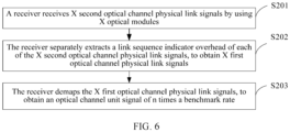
- this embodiment of the present invention provides a signal receiving method, including the following steps.
- a receiver receives X second optical channel physical link signals by using X optical modules.
- a rate of the second optical channel physical link signal is m; times a benchmark rate, m i ⁇ 1, and X ⁇ 2.
- the receiver separately extracts a link sequence indicator overhead of each of the X second optical channel physical link signals, to obtain X first optical channel physical link signals.
- the link sequence indicator overhead of each second optical channel physical link signal is used to indicate an order of a first optical channel physical link signal that corresponds to the second optical channel physical link signal, and a rate of the first optical channel physical link signal is m; times the benchmark rate.
- the benchmark rate in the present invention is 100 G, or 40 G.
- m i of all the X second optical channel physical link signals of m; times the benchmark rate may be the same, may be different, or may be partially the same. That is, any j of the X second optical channel physical link signals of m; times the benchmark rate have a same m i , where 2 ⁇ j ⁇ X.
- the optical channel unit signal of n times the benchmark rate is an optical channel data unit ODUKn signal of n times the benchmark rate.
- K is a level of an ODU or a level of an OTU. K is a positive integer, and a value of K is not specifically limited in this embodiment of the present invention.
- the ODUKn signal is an optical channel data unit ODUCn signal of a rate of n* 100 G
- the OTUKm i signal is an optical channel transport unit OTUCm; signal of a rate of m i *100 G, where C is a roman numeral for 100, and n and m; are both positive integers.
- the optical channel unit signal of n times the benchmark rate is an optical channel payload unit OPUKn signal of n times the benchmark rate.
- K is a level of an OPU or a level of an OTU, K is a positive integer, and a value of K is not specifically limited in this embodiment of the present invention.
- the OPUKn signal is an optical channel payload unit OPUCn signal of a rate of n*100 G
- the OTUKm i signal is an optical channel transport unit OTUCm; signal of a rate of m i *100 G, where C is a roman numeral for 100, and n and m i are both positive integers.
- the optical channel unit signal of n times the benchmark rate is an optical channel transport unit OTUKn signal of n times the benchmark rate.
- K is a level of an OTU, K is a positive integer, and a value of K is not specifically limited in this embodiment of the present invention.
- the OTUKm i signal is an optical channel transport unit OTUCm; signal of a rate of m i *100 G, and the OTUKn signal is an OTUCn signal of a rate of n*100 G, where C is a roman numeral for 100, and n and m i are both positive integers.
- a receiver receives X second optical channel physical link signals by using X optical modules.
- the receiver receives M optical carrier signals by using X optical fibers, where at least one optical carrier signal is received by using each optical fiber, and M ⁇ X ⁇ 2.
- the receiver demodulates the M optical carrier signals by using X preset optical modules, to obtain the X second optical channel physical link signals, where a rate of the second optical channel physical link signal is m; times the benchmark rate, m i ⁇ 1, and X ⁇ 2.
- the transmitter identifies a frame header of each second optical channel physical link subframe in each second optical channel physical link signal, and performs frame header alignment and sorting processing on all the subframes.
- the transmitter identifies frame header overheads carried by m i second OTU subframes in a frame structure of each second OTUKm i signal. (For each OTU subframe, the transmitter determines a frame header of each OTU subframe by identifying a special pattern of a frame header overhead FAS), and frame header alignment processing is performed on the m; second OTU subframes of the second OTUKm i signal.
- the receiver separately extracts a link sequence indicator overhead of each of the X second optical channel physical link signals, to obtain X first optical channel physical link signals.
- the link sequence indicator overhead of each second optical channel physical link signal is used to indicate an order of a first optical channel physical link signal that corresponds to the second optical channel physical link signal.
- the receiver may further separately extract an extended multiframe indicator overhead and a link group indicator overhead of each of the X second optical channel physical link signals.
- the extended multiframe indicator overhead is used to indicate a transmission delay
- the link group indicator overhead is used to indicate whether the X first optical channel physical link signals have a same source.
- the receiver extracts the link sequence indicator overhead in each second optical channel physical link signal, and aligns the link sequence indicator overheads.
- the receiver identifies a link sequence number of each first optical channel physical link signal according to a link sequence indicator, and performs resorting processing on the X first optical channel physical link signals, to generate X first optical channel physical link signals.
- the receiver demaps the X first optical channel physical link signals in a preset demapping manner, to obtain X groups of optical channel unit signals, where the preset demapping manner is bit synchronous demapping or asynchronous demapping, and a rate of each group of optical channel unit signals is m; times the benchmark rate.
- the preset demapping manner in this embodiment of the present invention is bit synchronous demapping.
- the preset demapping manner in this embodiment of the present invention may be asynchronous demapping. It should be noted that if the receiver uses the asynchronous demapping manner, to demap the X first optical channel physical link signals to X groups of optical channel unit subframe signals, before the asynchronous demapping, the receiver first needs to extract mapping overhead information.
- all subframes in a frame structure of the X groups of optical channel unit signals maintain frame alignment, and a frame structure of each group of optical channel unit subframe signals includes m; optical channel unit subframes.
- the receiver combines the X groups of optical channel unit signals, to generate the optical channel unit signal.
- the receiver may further perform forward error correction FEC decoding on the X second optical channel physical link signals.
- the receiver After performing related processing on the received X second optical channel physical link signals of m; times the benchmark rate, the receiver obtains X first optical channel physical link signals of m; times the benchmark rate, and the receiver obtains the optical channel unit signal of n times the benchmark rate by demapping the X first optical channel physical link signals.
- the receiver demodulates M optical carrier signals by using X existing low-rate optical modules, and no longer uses an optical module that matches a rate corresponding to the optical channel unit signal to perform demodulation, thereby reducing network costs when optical channel units of different rates need to use optical modules of different rates to perform demodulation.
- the optical channel unit signal is an optical channel data unit ODUKn signal
- the benchmark rate is 100 G
- the ODUKn signal in this embodiment of the present invention is an optical channel data unit ODUCn signal of a rate of n*100 G.
- the present invention can reduce network costs for sending ODUCns of different rates.
- this embodiment of the present invention provides a signal sending and receiving method, including the following steps.
- a transmitter maps a to-be-transmitted optical channel unit signal of n times a benchmark rate to X first optical channel physical link signals.
- the transmitter adds a link sequence indicator overhead to each of the X first optical channel physical link signals, to generate X second optical channel physical link signals.
- the transmitter performs forward error correction FEC encoding processing on the X second optical channel physical link signals.
- the transmitter modulates, by using X preset optical modules in a one-to-one correspondence manner, the X second optical channel physical link signals on which FEC encoding processing has been performed, to generate M optical carrier signals, and sends the M optical carrier signals by using X optical fibers.
- the receiver demodulates the M optical carrier signals by using the X preset optical modules, to obtain the X second optical channel physical link signals.
- a rate of the second optical channel physical link signal is m; times the benchmark rate, m i ⁇ 1, and X ⁇ 2.
- the receiver performs FEC decoding on the X second optical channel physical link signals.
- the receiver separately extracts a link sequence indicator overhead of each of the X second optical channel physical link signals on which FEC decoding has been performed, to obtain the X first optical channel physical link signals.
- the link sequence indicator overhead of each second optical channel physical link signal is used to indicate an order of a first optical channel physical link signal that corresponds to the second optical channel physical link signal, and a rate of the first optical channel physical link signal is m i times the benchmark rate.
- the benchmark rate in this embodiment of the present invention is 100 G. In another example, not covered by the claims, it may be 25 G.
- m i of all the X second optical channel physical link signals may be the same, may be different, or may be partially the same. That is, any j of the X second optical channel physical link signals of m; times the benchmark rate have a same m i , where 2 ⁇ j ⁇ X.
- the optical channel unit signal of n times the benchmark rate is an optical channel data unit ODUKn signal of n times the benchmark rate
- the first optical channel physical link signal of m times the benchmark rate is a first optical channel transport unit OTUKm i signal of m; times the benchmark rate.
- K is a level of an ODU or a level of an OTU, K is a positive integer, and a value of K is not specifically limited in this embodiment of the present invention.
- the ODUKn signal is an optical channel data unit ODUCn signal of a rate of n* 100 G
- the OTUKm i signal is an optical channel transport unit OTUCm; signal of a rate of m i *100 G, where C is a roman numeral for 100, and n and m i are both positive integers.
- the optical channel unit signal of n times the benchmark rate is an optical channel payload unit OPUKn signal of n times the benchmark rate
- the first optical channel physical link signal of m i times the benchmark rate is a first optical channel transport unit OTUKm i signal of m i times the benchmark rate.
- K is a level of an OPU or a level of an OTU
- K is a positive integer
- a value of K is not specifically limited in this embodiment of the present invention.
- the OPUKn signal is an optical channel payload unit OPUCn signal of a rate of n*100 G
- the OTUKm i signal is an optical channel transport unit OTUCm; signal of a rate of m i *100 G, where C is a roman numeral for 100, and n and m i are both positive integers.
- the optical channel unit signal of n times the benchmark rate is an optical channel transport unit OTUKn signal of n times the benchmark rate
- the first optical channel physical link signal of m i times the benchmark rate is an FEC frame whose payload area is an OTUKm i of m i times the benchmark rate.
- K is a level of an OTU
- K is a positive integer
- a value of K is not specifically limited in this embodiment of the present invention.
- the OTUKm i signal is an optical channel transport unit OTUCm i signal of a rate of m i *100 G
- the OTUKn signal is an OTUCn signal of a rate of n*100 G, where C is a roman numeral for 100, and n and m i are both positive integers.
- S301 to S304 in this embodiment of the present invention are the same as the method described in Embodiment 1, and details are not described herein again.
- an optical channel unit signal of n times a benchmark rate is no longer mapped to a first optical channel physical link signal of a same rate as the optical channel unit signal, but is mapped to X first optical channel physical link signals of m; times the benchmark rate.
- X existing low-rate optical modules can be used to modulate X signals, and an optical module that matches a rate corresponding to an optical channel unit signal is no longer used for modulation, thereby reducing network costs when optical channel units of different rates need to use optical modules of different rates to perform modulation.
- the optical channel unit signal is an optical channel data unit ODUKn signal
- the benchmark rate is 100 G
- the ODUKn signal in this embodiment of the present invention is an optical channel data unit ODUCn signal of a rate of n*100 G.
- the present invention can reduce network costs for sending ODUCns of different rates.
- an optical channel unit signal of n times a benchmark rate is an optical channel data unit ODUKn signal of n times the benchmark rate, a first optical channel physical link signal of m; times the benchmark rate is a first optical channel transport unit OTUKm i signal of m; times the benchmark rate.
- an optical channel unit signal of n times a benchmark rate is an optical channel transport unit OTUKn signal of n times the benchmark rate, a first optical channel physical link signal of m; times the benchmark rate is a signal whose payload area of an FEC frame is an OTUKm i of m; times the benchmark rate.
- an optical channel unit signal of n times a benchmark rate is an optical channel payload unit OPUKn signal of n times the benchmark rate, a first optical channel physical link signal of m; times the benchmark rate is a first optical channel transport unit OTUKm i signal of m; times the benchmark rate.
- the ODUKn signal is an optical channel data unit ODUCn signal of a rate of n* 100 G
- the OTUKm i signal is an optical channel transport unit OTUCm; signal of a rate of m;* 100 G
- the OTUKn signal is an OTUCn signal of a rate of n*100 G
- the OPUKn signal is an optical channel payload unit OPUCn signal of a rate of n*100 G.
- a signal sending and receiving method is described by using an example in which the optical channel unit signal of n times the benchmark rate is an ODUCn signal, and the first optical channel physical link signal of m; times the benchmark rate is a first OTUCm; signal.
- this embodiment of the present invention provides a signal sending and receiving method, including the following steps.
- a method for mapping, by a transmitter, a to-be-transmitted ODUCn signal to X first OTUCm i signals is: dividing, by the transmitter, n ODU subframes in a frame structure of the ODUCn signal into X preset groups according to a quantity of preset optical modules and a bearer rate of the preset optical modules, where each group of ODU subframes includes m; ODU subframes; and mapping, by the transmitter in a preset mapping manner, X groups of ODUCm i subframe signals that each include m; ODU subframes to X first OTUCm i signals.
- the preset mapping manner in this embodiment of the present invention is bit synchronous mapping or asynchronous mapping.
- the transmitter maps an ODUC4 to four first OTUC1 signals.
- the transmitter maps an ODUC4 to two first OTUC2 signals.
- the transmitter maps an ODUC4 to two first OTUC1 signals and one first OTUC2 signal.
- the transmitter adds a link sequence indicator overhead to each of the X first OTUCm; signals, to generate X second OTUCm i signals.
- the link sequence indicator overhead of each first OTUCm; signal is used to indicate an order of the first OTUCm; signal. That is, the link sequence indicator overhead of each first OTUCm; signal is used to indicate a sequence number of the current first OTUCm; signal in the X first OTUCm; signals.
- the transmitter first performs link sequence numbering processing on the X first OTUCm; signals. Then, the transmitter respectively and synchronously adds link sequence numbers of the X first OTUCm; signals to the link sequence indicator overheads of all the X first OTUCm i signals.
- the transmitter adds the link sequence indicator overhead to an overhead range of a frame structure of each first OTUCm; signal; or adds the link sequence indicator overhead to a frame header of a frame structure of each first OTUCm; signal.
- the transmitter adds the link sequence indicator overhead to the overhead range of the frame structure of each first OTUCm; signal.
- the transmitter may further add an extended multiframe indicator overhead and a link group indicator overhead to each of the X first OTUCm; signals.
- the extended multiframe indicator overhead is used to indicate a transmission delay
- the link group indicator overhead is used to indicate whether the X first OTUCm; signals have a same source.
- a receiver can determine, according to the link group indicator overhead, whether the X first OTUCm; signals are sent by a same transmitter.
- the transmitter further adds first overhead information to each of the X first OTUCm i signals.
- the first overhead information is used to indicate link bandwidth adjustment of the X first OTUCm; signals, and the first overhead information includes at least a link bandwidth adjustment request, a link bandwidth adjustment response, and a link member status indication. If a link bandwidth of the X first OTUCm i signals does not meet a requirement, the link bandwidth of the X first OTUCm; signals may be adjusted according to the first overhead information.
- the transmitter further adds a subframe sequence indicator overhead OTUK ID to each of the X first OTUCm; signals, where the OTUK ID is used to indicate an order of m; OTU subframes in each first OTUKm i signal.
- the OTUK ID may substitute for the link sequence indicator overhead.
- the transmitter further separately generates and adds link segment monitoring overhead information SM to each of the X second OTUCmi signals.
- the transmitter adds a frame header indication overhead FAS to each of the X second OTUCm i signals. That is, a pattern 0xf6f62828 is added to the first row and the second to the fifth columns of each OTU subframe. For specific information of the pattern 0xf6f62828, refer to the existing protocol.
- the transmitter further adds a logical lane marker LLM to each of the X second OTUCm; signals.
- the LLMs are used as markers for multiple logical channels. LLMs of all subframes in a frame structure of each second OTUCm i signal are the same. An initial value of an LLM is 0, values of all LLMs are in ascending order, and a value range of the LLM is 0 to 239.
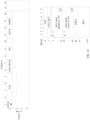
- a frame structure of the second OTUC1 signal is shown in FIG. 12 , FIG. 13 , or FIG. 14 .
- a GID is a group marker of an OTUC1-X.
- An OTUC ID may be placed in the first row and the first column of an OTUC frame, or may be placed in the first row and the 14 th column of an OTUC frame.
- the OTUC ID is indicated in a multiframe manner.
- the OTUC ID may substitute for a function of a link sequence indicator overhead SQ ID, that is, the OTUC ID is the link sequence indicator overhead.
- a GID is a group marker of an OTUC1-X.
- An OTUC ID may be placed in the first row and the first column of an OTUC frame, or may be placed in the first row and the 14 th column of an OTUC frame.
- the OTUC ID is indicated in a multiframe manner.
- the OTUC ID may substitute for a function of a link sequence indicator overhead SQ, that is, the OTUC ID is the link sequence indicator overhead.
- Second overhead information includes a PHY MAP Request, a PHY MAP Active, or the like.
- a function of each overhead field is described as follows.
- PHY MAP Request 256 bits. One bit corresponds to one OTUC1, and the zeroth to the 255 th bits respectively correspond to the first to the 256 th OTUC1.
- the PHY MAP Request is used for an increase request indication or a decrease request indication in an OTUC1-X bandwidth adjustment process. When the value changes from 0 to 1, it indicates an increase request. When the value changes from 1 to 0, it indicates a decrease request.
- PHY MAP Request 256 bits. One bit corresponds to one OTUC1, and the zeroth to the 255 th bits respectively correspond to the first to the 256 th OTUC1.
- the PHY MAP Request is used for a response in an OTUC1-X bandwidth adjustment process. When the value is 1, it indicates that a corresponding increase or decrease request is agreed to be performed. Otherwise, the value is 0.
- CRC8 8 bits, used to store check information after 8-bit cyclic redundancy check is performed on the foregoing overhead area information.
- an overhead carrying manner of the second OTUC1 signal is different from those in FIG. 12 and FIG. 13 .
- a generic framing procedure GFP, Generic Framing Procedure
- frame packet encapsulation manner is used for overhead carrying and transfer. First, the transmitter encapsulates some overheads in a GFP frame, and then transfers the GFP frame by using a GCC0 overhead channel of an OTUC1.
- a definition of the GFP frame refer to a specific definition in the standard ITU-T G.7041.
- Overheads encapsulated in the GFP frame include a GID, an MSID, CTRL, RAS, and an MSF.
- the GID is a group marker of the OTUC1-X.
- the MSID Member Sequence ID
- a function of each overhead field is similar to that described in FIG. 4 .
- the transmitter performs FEC encoding processing on the X second OTUCm i signals.
- the transmitter modulates, by using X preset optical modules in a one-to-one correspondence manner, the X second OTUCm i signals on which FEC encoding processing has been performed, to generate M optical carrier signals, and sends the M optical carrier signals by using X optical fibers.
- a receiver demodulates the M optical carrier signals by using the X preset optical modules, to obtain the X second OTUCm i signals.
- a rate of the second OTUCmi signal is m i times a benchmark rate, m i ⁇ 1, and X ⁇ 2.
- the receiver performs FEC decoding on the X second OTUCm i signals.
- the receiver separately extracts a link sequence indicator overhead of each of the X second OTUCm i signals on which FEC decoding has been performed, to obtain the X first OTUCm i signals.
- the link sequence indicator overhead of each second OTUCm i signal is used to indicate an order of a first optical channel physical link signal that corresponds to the second optical channel physical link signal.
- This embodiment of the present invention provides a signal sending and receiving method. After mapping a to-be-transmitted ODUCn signal to X first OTUCm i signals, a transmitter adds a link sequence indicator overhead to each of the X first OTUCm i signals, to generate X second OTUCm i signals, where n ⁇ 2, X ⁇ 2, m i ⁇ 1, m 1 +m 2 +.. .+m i +..
- the link sequence indicator overhead of each first OTUCm i signal is used to indicate an order of the first OTUCm i signal, and then the transmitter modulates and sends the X second OTUCm i signals by using X preset optical modules in a one-to-one correspondence manner.
- an ODUCn signal is no longer mapped to an OTUCn signal of a same rate as the ODUCn signal, but is mapped to X first OTUCm i signals.
- X existing low-rate optical modules can be used to modulate X signals, and an optical module that matches a rate corresponding to an optical channel unit signal is no longer used for modulation, thereby reducing network costs when optical channel units of different rates need to use optical modules of different rates to perform modulation.
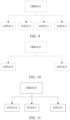
- the transmitter 1 includes:
- the transmitter 1 further includes a grouping unit 14, where the grouping unit 14 is configured to divide the to-be-transmitted optical channel unit signal of n times the benchmark rate into X preset groups.
- mapping unit 10 is specifically configured to map the X groups of optical channel unit signals obtained through division by the grouping unit 14 to the X first optical channel physical link signals in a one-to-one correspondence manner and in a preset mapping manner, where the preset mapping manner is bit synchronous mapping or asynchronous mapping.
- the transmitter further includes an encoding unit 15, where the modulation unit 15 is configured to: before the modulation unit 12 modulates the X second optical channel physical link signals by using the X preset optical modules in the one-to-one correspondence manner, perform forward error correction FEC encoding processing on the X second optical channel physical link signals generated by the overhead addition unit 11.
- the optical channel unit signal of n times the benchmark rate is an optical channel data unit ODUKn signal of n times the benchmark rate
- the first optical channel physical link signal of m; times the benchmark rate is a first optical channel transport unit OTUKm i signal of m i times the benchmark rate.
- This embodiment of the present invention provides a transmitter, which mainly includes a mapping unit, an overhead addition unit, a modulation unit, and a sending unit. After mapping a to-be-transmitted optical channel unit signal of n times a benchmark rate to X first optical channel physical link signals of m; times the benchmark rate, the transmitter adds a link sequence indicator overhead to each first optical channel physical link signal of m; times the benchmark rate of the X first optical channel physical link signals of m; times the benchmark rate, to generate X second optical channel physical link signals of m; times the benchmark rate, where n ⁇ 2, X ⁇ 2, m i ⁇ 1, m 1 +m 2 +.. .+m i +..
- the link sequence indicator overhead of each first optical channel physical link signal is used to indicate an order of the first optical channel physical link signal, and then the transmitter modulates and sends the X second optical channel physical link signals of m i times the benchmark rate by using X preset optical modules in a one-to-one correspondence manner.
- an optical channel unit signal of n times a benchmark rate is no longer mapped to a first optical channel physical link signal of a same rate as the optical channel unit signal, but is mapped to X first optical channel physical link signals of m; times the benchmark rate.
- X existing low-rate optical modules can be used to modulate X signals, and an optical module that matches a rate corresponding to an optical channel unit signal is no longer used for modulation, thereby reducing network costs when optical channel units of different rates need to use optical modules of different rates to perform modulation.
- the optical channel unit signal is an optical channel data unit ODUKn signal
- the benchmark rate is 100 G
- the ODUKn signal in this embodiment of the present invention is an optical channel data unit ODUCn signal of a rate of n*100 G.
- the present invention can reduce network costs for sending ODUCns of different rates.
- the receiver 1 includes:
- the demapping unit 22 is specifically configured to demap the X first optical channel physical link signals in a preset demapping manner, to obtain X groups of optical channel unit signals, where the preset demapping manner is bit synchronous demapping or asynchronous demapping, and a rate of each group of optical channel unit signals is m; times the benchmark rate.
- the receiver 1 further includes a combination unit 23, where the combination unit 23 is specifically configured to combine the X groups of optical channel unit subframe signals obtained by the demapping unit 22, to generate the optical channel unit signal of n times the benchmark rate.
- the receiver 1 further includes a decoding unit 24, where the decoding unit 24 is configured to: before the extraction unit 21 separately extracts the link sequence indicator overhead of each of the X second optical channel physical link signals, to obtain the X first optical channel physical link signals, perform forward error correction FEC decoding on the X second optical channel physical link signals received by the receiving unit.
- the optical channel unit signal of n times the benchmark rate is an optical channel data unit ODUKn signal of n times the benchmark rate.
- This embodiment of the present invention provides a receiver, which mainly includes a receiving unit, an extraction unit, and a demapping unit.
- the receiver After performing related processing on the received X second optical channel physical link signals of m; times the benchmark rate, the receiver obtains X first optical channel physical link signals of m; times the benchmark rate, and the receiver obtains the optical channel unit signal of n times the benchmark rate by demapping the X first optical channel physical link signals.
- the receiver demodulates M optical carrier signals by using X existing low-rate optical modules, and no longer uses an optical module that matches a rate corresponding to the optical channel unit signal to perform demodulation, thereby reducing network costs when optical channel units of different rates need to use optical modules of different rates to perform demodulation.
- the optical channel unit signal is an optical channel data unit ODUKn signal
- the benchmark rate is 100 G
- the ODUKn signal in this embodiment of the present invention is an optical channel data unit ODUCn signal of a rate of n*100 G.
- the present invention can reduce network costs for sending ODUCns of different rates.
- the transfer device includes a transceiver 30, a processor 31, a memory 32, and a system bus 33, where the transceiver 30, the processor 31, and the memory 32 are connected to and communicate with each other by using the system bus 33.
- the processor 31 may be a single-core or multi-core central processing unit, or an application-specific integrated circuit, or one or more integrated circuits configured to implement this embodiment of the present invention.
- the memory 32 may be a high-speed random access memory (RAM, Random Access Memory) memory, and may be a non-volatile memory (Non-volatile Memory), for example, at least one magnetic disk storage.
- RAM Random Access Memory
- Non-volatile Memory for example, at least one magnetic disk storage.
- the transfer device in this embodiment of the present invention may be a sending device, or may be a receiving device.
- the transfer device may map a to-be-transmitted optical channel unit signal of n times a benchmark rate to X first optical channel physical link signals, perform related processing on the X first optical channel physical link signals, and send the processed X first optical channel physical link signals.
- the transfer device may demap received X second optical channel physical link signals to obtain an optical channel unit signal of n times a benchmark rate.
- the transceiver 30 is configured to send the X second optical channel physical link signals modulated by the processor 31.
- the processor 31 is specifically configured to divide the to-be-transmitted optical channel unit signal of n times the benchmark rate into X preset groups; and specifically configured to map the X groups of optical channel unit signals to the X first optical channel physical link signals in a one-to-one correspondence manner and in a preset mapping manner, where the preset mapping manner is bit synchronous mapping or asynchronous mapping.
- the processor 31 is further configured to: before modulating the X second optical channel physical link signals by using the X preset optical modules in the one-to-one correspondence manner, perform forward error correction FEC encoding processing on the X second optical channel physical link signals.
- the optical channel unit signal of n times the benchmark rate is an optical channel data unit ODUKn signal of n times the benchmark rate
- the first optical channel physical link signal of m; times the benchmark rate is a first optical channel transport unit OTUKm i signal of m; times the benchmark rate.
- the optical channel unit signal of n times the benchmark rate is an optical channel payload unit OPUKn signal of n times the benchmark rate
- the first optical channel physical link signal of m; times the benchmark rate is a first optical channel transport unit OTUKm i signal of m; times the benchmark rate.
- the optical channel unit signal of n times the benchmark rate is an optical channel transport unit OTUKn signal of n times the benchmark rate
- the first optical channel physical link signal of m; times the benchmark rate is an FEC frame whose payload area is an OTUKm i of m i times the benchmark rate.
- the ODUKn signal is an optical channel data unit ODUCn signal of a rate of n* 100 G
- the OTUKm i signal is an optical channel transport unit OTUCm i signal of a rate of m i *100 G
- the OTUKn signal is an OTUCn signal of a rate of n*100 G.
- the transceiver 30 is further configured to receive X second optical channel physical link signals by using X optical modules, where a rate of the second optical channel physical link signal is m i times a benchmark rate, m i ⁇ 1, and X ⁇ 2.
- the processor 31 is specifically configured to demap the X first optical channel physical link signals in a preset demapping manner, to obtain X groups of optical channel unit signals, where the preset demapping manner is bit synchronous demapping or asynchronous demapping, and a rate of each group of optical channel unit signals is m; times the benchmark rate; and specifically configured to combine the X groups of optical channel unit subframe signals, to generate the optical channel unit signal of n times the benchmark rate.
- the processor 31 is further configured to: before separately extracting the link sequence indicator overhead of each of the X second optical channel physical link signals, to obtain the X first optical channel physical link signals, perform forward error correction FEC decoding on the X second optical channel physical link signals received by the receiving unit.
- an optical channel unit signal of n times a benchmark rate is no longer mapped to a first optical channel physical link signal of a same rate as the optical channel unit signal, but is mapped to X first optical channel physical link signals of m; times the benchmark rate.
- X existing low-rate optical modules can be used to modulate X signals, and an optical module that matches a rate corresponding to an optical channel unit signal is no longer used for modulation, thereby reducing network costs when optical channel units of different rates need to use optical modules of different rates to perform modulation.
- the optical channel unit signal is an optical channel data unit ODUKn signal
- the benchmark rate is 100 G
- the ODUKn signal in this embodiment of the present invention is an optical channel data unit ODUCn signal of a rate of n*100 G.
- the present invention can reduce network costs for sending ODUCns of different rates.
- the system includes the transmitter 3 that has any one of the foregoing features and the receiver 4 that has any one of the foregoing features.
- This embodiment of the present invention provides a signal transmission system. After mapping a to-be-transmitted optical channel unit signal of n times a benchmark rate to X first optical channel physical link signals of m; times the benchmark rate, a transmitter adds a link sequence indicator overhead to each first optical channel physical link signal of m; times the benchmark rate of the X first optical channel physical link signals of m i times the benchmark rate, to generate X second optical channel physical link signals of m i times the benchmark rate, where n ⁇ 2, X ⁇ 2, m i ⁇ 1, m 1 +m 2 +.... .+m i +..
- the link sequence indicator overhead of each first optical channel physical link signal is used to indicate an order of the first optical channel physical link signal, and then the transmitter modulates and sends the X second optical channel physical link signals of m i times the benchmark rate by using X preset optical modules in a one-to-one correspondence manner.
- an optical channel unit signal of n times a benchmark rate is no longer mapped to a first optical channel physical link signal of a same rate as the optical channel unit signal, but is mapped to X first optical channel physical link signals of m i times the benchmark rate.
- X existing low-rate optical modules can be used to modulate X signals, and an optical module that matches a rate corresponding to an optical channel unit signal is no longer used for modulation, thereby reducing network costs when optical channel units of different rates need to use optical modules of different rates to perform modulation.
- the optical channel unit signal is an optical channel data unit ODUKn signal
- the benchmark rate is 100 G
- the ODUKn signal in this embodiment of the present invention is an optical channel data unit ODUCn signal of a rate of n*100 G.
- the present invention can reduce network costs for sending ODUCns of different rates.
- the disclosed system, apparatus, and method may be implemented in other manners.
- the described apparatus embodiment is merely exemplary.
- the module or unit division is merely logical function division and may be other division in actual implementation.
- a plurality of units or components may be combined or integrated into another system, or some features may be ignored or not performed.
- the displayed or discussed mutual couplings or direct couplings or communication connections may be implemented by using some interfaces.
- the indirect couplings or communication connections between the apparatuses or units may be implemented in electronic, mechanical, or other forms.
- the units described as separate parts may or may not be physically separate. Parts displayed as units may or may not be physical units, and may be located in one position or may be distributed on a plurality of network units. Some or all of the units may be selected according to actual needs to achieve the objectives of the solutions of the embodiments.
- functional units in the embodiments of the present invention may be integrated into one processing unit, or each of the units may exist alone physically, or two or more units are integrated into one unit.
- the integrated unit may be implemented in a form of hardware, or may be implemented in a form of a software functional unit.
- the program may be stored in a computer readable storage medium. When the program runs, the steps of the method embodiments are performed.
- the foregoing storage medium includes: any medium that can store program code, such as a ROM, a RAM, a magnetic disk, or an optical disc.
Landscapes
- Engineering & Computer Science (AREA)
- Computer Networks & Wireless Communication (AREA)
- Signal Processing (AREA)
- Physics & Mathematics (AREA)
- Electromagnetism (AREA)
- Computer Security & Cryptography (AREA)
- Time-Division Multiplex Systems (AREA)
- Optical Communication System (AREA)
- Detection And Prevention Of Errors In Transmission (AREA)
Claims (12)
- Signalsendeverfahren, umfassend:Abbilden (S101) eines Optische-Transporteinheit- bzw. OTUKn-Signals auf X Vorwärtsfehlerkorrektur- bzw. FEC-Rahmen, wobei eine Rate des OTUKn-Signals n mal eine Referenzrate ist, eine Rate eines Nutzdatenbereichs jedes der X FEC-Rahmen mi mal die Referenzrate ist und n ≥ 2, X ≥ 2,
 Hinzufügen (S102) eines Verbindungssequenzindikators zu jedem der X FEC-Rahmen, wobei der Verbindungssequenzindikator jedes der X FEC-Rahmen verwendet wird, um eine Reihenfolge der X FEC-Rahmen anzugeben; undSenden (S103) der X FEC-Rahmen jeweils unter Verwendung von X optischen Modulen, wobei eine Rate jedes der X optischen Module einer Rate jedes der X FEC-Rahmen entspricht.
 - Signalsendeverfahren nach Anspruch 1, wobei das Abbilden eines OTUKn-Signals auf X FEC-Rahmen Folgendes umfasst:Aufteilen des OTUKn-Signals in X Gruppen; undAbbilden der X Gruppen des OTUKn-Signals jeweils auf die X FEC-Rahmen unter Verwendung einer bitsynchronen Abbildungsprozedur.
- Signalsendeverfahren nach Anspruch 1, wobei das Abbilden eines OTUKn-Signals auf X FEC-Rahmen Folgendes umfasst:Aufteilen des OTUKn-Signals in X Gruppen; undAbbilden der X Gruppen des OTUKn-Signals jeweils auf die X FEC-Rahmen unter Verwendung einer bitasynchronen Abbildungsprozedur.
- Signalsendeverfahren nach einem der Ansprüche 1 bis 3, wobei das Signalsendeverfahren vor dem Senden der X FEC-Rahmen jeweils unter Verwendung von X optischen Modulen ferner Folgendes umfasst:
Ausführen von FEC-Codierung an den X FEC-Rahmen. - Signalsendeverfahren nach einem der Ansprüche 1 bis 4, wobei beliebige j der X FEC-Rahmen ein selbes mi aufweisen, wobei 2≤j≤X ist.
- Signalsendeverfahren nach einem der Ansprüche 1 bis 4, wobei jeder der X FEC-Rahmen ein anderes mi aufweist.
- Signalsendeverfahren nach einem der Ansprüche 1 bis 6, wobei das Signalsendeverfahren ferner Folgendes umfasst:
Hinzufügen eines Verbindungsgruppenindikators zu jedem der X FEC-Rahmen, wobei der Verbindungsgruppenindikator verwendet wird, um anzugeben, ob die X FEC-Rahmen eine selbe Quelle aufweisen. - Signalsendevorrichtung, umfassend:Mittel zum Abbilden eines Optische-Transporteinheit- bzw. OTUKn-Signals auf X Vorwärtsfehlerkorrektur- bzw. FEC-Rahmen, wobei eine Rate des OTUKn-Signals n mal eine Referenzrate ist, eine Rate eines Nutzdatenbereichs jedes der X FEC-Rahmen mi mal die Referenzrate ist und n ≥ 2, X ≥ 2,
 Mittel zum Hinzufügen eines Verbindungssequenzindikators zu jedem der X FEC-Rahmen, wobei der Verbindungssequenzindikator jedes der X FEC-Rahmen verwendet wird, um eine Reihenfolge der X FEC-Rahmen anzugeben; undX optische Module zum Senden der X FEC-Rahmen, wobei eine Rate jedes der X optischen Module einer Rate jedes der X FEC-Rahmen entspricht.
 - Signalsendevorrichtung nach Anspruch 8, wobei die Mittel zum Abbilden eines OTUKn-Signals auf X FEC-Rahmen Folgendes umfassen:Mittel zum Aufteilen des OTUKn-Signals in X Gruppen; undMittel zum Abbilden der X Gruppen des OTUKn-Signals jeweils auf die X FEC-Rahmen unter Verwendung einer bitsynchronen Abbildungsprozedur.
- Signalsendevorrichtung nach Anspruch 8, wobei die Mittel zum Abbilden eines OTUKn-Signals auf die X FEC-Rahmen Folgendes umfassen:Mittel zum Aufteilen des OTUKn-Signals in X Gruppen; undMittel zum Abbilden der X Gruppen des OTUKn-Signals jeweils auf die X FEC-Rahmen unter Verwendung einer bitasynchronen Abbildungsprozedur.
- Signalsendevorrichtung nach einem der Ansprüche 8 bis 10, wobei die Vorrichtung ferner Folgendes umfasst:
Mittel zum Ausführen von FEC-Codierung an den X FEC-Rahmen. - Signalsendevorrichtung nach einem der Ansprüche 8 bis 11, wobei beliebige j der X FEC-Rahmen ein selbes mi aufweisen, wobei 2≤j≤X ist.
Applications Claiming Priority (3)
| Application Number | Priority Date | Filing Date | Title |
|---|---|---|---|
| CN201510624117.1A CN106559141B (zh) | 2015-09-25 | 2015-09-25 | 一种信号发送、接收方法、装置及系统 |
| EP16847909.5A EP3343805B1 (de) | 2015-09-25 | 2016-08-05 | Signalsende- und -empfangsverfahren, -vorrichtung und -system |
| PCT/CN2016/093576 WO2017050027A1 (zh) | 2015-09-25 | 2016-08-05 | 一种信号发送、接收方法、装置及系统 |
Related Parent Applications (1)
| Application Number | Title | Priority Date | Filing Date |
|---|---|---|---|
| EP16847909.5A Division EP3343805B1 (de) | 2015-09-25 | 2016-08-05 | Signalsende- und -empfangsverfahren, -vorrichtung und -system |
Publications (3)
| Publication Number | Publication Date |
|---|---|
| EP3843293A1 EP3843293A1 (de) | 2021-06-30 |
| EP3843293B1 true EP3843293B1 (de) | 2024-12-04 |
| EP3843293C0 EP3843293C0 (de) | 2024-12-04 |
Family
ID=58385827
Family Applications (2)
| Application Number | Title | Priority Date | Filing Date |
|---|---|---|---|
| EP16847909.5A Active EP3343805B1 (de) | 2015-09-25 | 2016-08-05 | Signalsende- und -empfangsverfahren, -vorrichtung und -system |
| EP20203998.8A Active EP3843293B1 (de) | 2015-09-25 | 2016-08-05 | Signalsendevorrichtung und -system |
Family Applications Before (1)
| Application Number | Title | Priority Date | Filing Date |
|---|---|---|---|
| EP16847909.5A Active EP3343805B1 (de) | 2015-09-25 | 2016-08-05 | Signalsende- und -empfangsverfahren, -vorrichtung und -system |
Country Status (10)
| Country | Link |
|---|---|
| US (3) | US10601514B2 (de) |
| EP (2) | EP3343805B1 (de) |
| JP (1) | JP6779285B2 (de) |
| KR (1) | KR102048332B1 (de) |
| CN (1) | CN106559141B (de) |
| BR (1) | BR112018005670B1 (de) |
| CA (1) | CA2999789C (de) |
| ES (2) | ES2840676T3 (de) |
| RU (1) | RU2683287C1 (de) |
| WO (1) | WO2017050027A1 (de) |
Families Citing this family (5)
| Publication number | Priority date | Publication date | Assignee | Title |
|---|---|---|---|---|
| CN106559141B (zh) * | 2015-09-25 | 2020-01-10 | 华为技术有限公司 | 一种信号发送、接收方法、装置及系统 |
| CN109962802A (zh) * | 2017-12-26 | 2019-07-02 | 中兴通讯股份有限公司 | 带宽调整方法、装置、系统、传送平面节点及存储介质 |
| CN110224946B (zh) | 2018-03-01 | 2022-05-27 | 中兴通讯股份有限公司 | 一种业务发送方法及装置、业务接收方法及装置 |
| CN115412782A (zh) * | 2021-05-28 | 2022-11-29 | 中兴通讯股份有限公司 | 带宽调整方法及装置、存储介质、电子装置 |
| US12192102B2 (en) | 2022-01-27 | 2025-01-07 | Eagle Technology, Llc | System and method for transport overhead and header field cybersecurity |
Family Cites Families (36)
| Publication number | Priority date | Publication date | Assignee | Title |
|---|---|---|---|---|
| US2884687A (en) * | 1959-05-05 | Wear-resistant sintered powdered metal | ||
| JP4597583B2 (ja) * | 2004-05-31 | 2010-12-15 | シャープ株式会社 | データ送信装置、データ受信装置、通信システム、データ送信装置の制御プログラム、データ受信装置の制御プログラム、および、コンピュータ読み取り可能な記録媒体 |
| CN100373847C (zh) | 2004-12-14 | 2008-03-05 | 华为技术有限公司 | 在光传送网中传输低速率业务信号的方法 |
| US7444443B2 (en) * | 2005-02-28 | 2008-10-28 | Freescale Semiconductor, Inc. | Method of repeating data transmission between network devices by timing a first predetermined period after previous first data transmission |
| JP2006253852A (ja) * | 2005-03-09 | 2006-09-21 | Hitachi Ltd | 可変通信容量データ伝送装置及びデータ伝送装置 |
| CN101291179B (zh) | 2007-04-17 | 2011-03-23 | 华为技术有限公司 | 一种光传送网中客户信号传送方法及相关设备 |
| CN101389146B (zh) | 2007-09-13 | 2011-01-05 | 华为技术有限公司 | 光传送网同步交叉调度的方法和装置 |
| CN100589365C (zh) | 2007-09-14 | 2010-02-10 | 中兴通讯股份有限公司 | 一种光传输网中光净荷单元的时隙划分与开销处理的方法 |
| US8532066B2 (en) | 2007-10-18 | 2013-09-10 | Qualcomm Incorporated | Transmission structure supporting multi-user scheduling and MIMO transmission |
| US8045863B2 (en) | 2007-12-26 | 2011-10-25 | Ciena Corporation | Byte-interleaving systems and methods for 100G optical transport enabling multi-level optical transmission |
| US8213446B2 (en) | 2007-12-26 | 2012-07-03 | Ciena Corporation | Frame-interleaving systems and methods for 100G optical transport enabling multi-level optical transmission |
| CN101547057A (zh) * | 2008-03-28 | 2009-09-30 | 中兴通讯股份有限公司 | 光传送网中业务处理的方法和装置 |
| CN101635867B (zh) | 2008-07-21 | 2012-08-08 | 华为技术有限公司 | 光信号的复用映射和解复用映射方法、装置及系统 |
| CN101729940B (zh) | 2008-10-22 | 2013-06-05 | 华为技术有限公司 | 向多路通信通道发送数据的方法及接收数据的方法 |
| CN101841749B (zh) * | 2009-03-18 | 2013-10-02 | 华为技术有限公司 | 数据传输方法、通信装置及通信系统 |
| JP5419534B2 (ja) * | 2009-05-11 | 2014-02-19 | 三菱電機株式会社 | Fecフレーム構成装置および方法 |
| WO2010140192A1 (ja) * | 2009-06-03 | 2010-12-09 | 株式会社 東芝 | 通信装置 |
| CN101826920B (zh) | 2010-04-13 | 2014-01-01 | 中兴通讯股份有限公司 | 用于otn设备的交叉容量处理方法和otn设备 |
| EP2741454B1 (de) | 2011-08-24 | 2015-07-08 | Huawei Technologies Co., Ltd. | Verfahren und vorrichtung zur übertragung eines ultrahochgeschwindigkeits-ethernet-dienstes |
| WO2012163033A1 (zh) | 2011-10-31 | 2012-12-06 | 华为技术有限公司 | 数据发送器、数据接收器和帧同步方法 |
| JP5799872B2 (ja) * | 2012-03-28 | 2015-10-28 | 富士通株式会社 | 光送信器、光受信器、及び光伝送方法 |
| WO2012126421A2 (zh) * | 2012-05-15 | 2012-09-27 | 华为技术有限公司 | 一种光传送网的数据处理方法、相关设备及系统 |
| CN102893629A (zh) * | 2012-06-01 | 2013-01-23 | 华为技术有限公司 | 光传送网中传送客户信号的方法及传送设备 |
| WO2013185327A1 (zh) * | 2012-06-14 | 2013-12-19 | 华为技术有限公司 | 传送、接收客户信号的方法和装置 |
| JP5975103B2 (ja) * | 2012-07-20 | 2016-08-23 | 富士通株式会社 | 伝送装置 |
| CN106301661B (zh) * | 2012-07-30 | 2018-10-19 | 华为技术有限公司 | 光传送网中传送、接收客户信号的方法和装置 |
| CN103595515B (zh) * | 2012-08-13 | 2018-08-31 | 中兴通讯股份有限公司 | 光传送网的数据映射方法及装置 |
| CN103716108B (zh) * | 2012-09-29 | 2018-08-03 | 中兴通讯股份有限公司 | 光传送网的数据映射方法及装置 |
| CN103780327B (zh) | 2012-10-18 | 2018-12-04 | 中兴通讯股份有限公司 | 数据传送方法及装置 |
| EP2738964A1 (de) * | 2012-12-03 | 2014-06-04 | Alcatel Lucent | Verfahren und Vorrichtung zur Übertragung eines asynchronen Transportsignals über einen optischen Abschnitt |
| CN103997426B (zh) * | 2013-02-17 | 2018-11-16 | 中兴通讯股份有限公司 | 一种反向复用中子帧错序的检测方法及节点 |
| CN103997388B (zh) * | 2013-02-18 | 2019-04-23 | 中兴通讯股份有限公司 | 数据的映射、解映射方法及装置 |
| CN106464374B (zh) * | 2014-05-08 | 2019-06-07 | 三菱电机株式会社 | 光传输方法及光传输系统 |
| JP6323193B2 (ja) * | 2014-06-12 | 2018-05-16 | 富士通株式会社 | 光送信装置および故障判断方法 |
| US10116403B2 (en) | 2014-08-25 | 2018-10-30 | Ciena Corporation | OTN adaptation for support of subrate granularity and flexibility and for distribution across multiple modem engines |
| CN106559141B (zh) * | 2015-09-25 | 2020-01-10 | 华为技术有限公司 | 一种信号发送、接收方法、装置及系统 |
-
2015
- 2015-09-25 CN CN201510624117.1A patent/CN106559141B/zh active Active
-
2016
- 2016-08-05 RU RU2018115229A patent/RU2683287C1/ru active
- 2016-08-05 BR BR112018005670-7A patent/BR112018005670B1/pt active IP Right Grant
- 2016-08-05 JP JP2018515515A patent/JP6779285B2/ja active Active
- 2016-08-05 EP EP16847909.5A patent/EP3343805B1/de active Active
- 2016-08-05 WO PCT/CN2016/093576 patent/WO2017050027A1/zh not_active Ceased
- 2016-08-05 ES ES16847909T patent/ES2840676T3/es active Active
- 2016-08-05 KR KR1020187011298A patent/KR102048332B1/ko active Active
- 2016-08-05 ES ES20203998T patent/ES3012008T3/es active Active
- 2016-08-05 EP EP20203998.8A patent/EP3843293B1/de active Active
- 2016-08-05 CA CA2999789A patent/CA2999789C/en active Active
-
2018
- 2018-03-23 US US15/934,623 patent/US10601514B2/en active Active
-
2020
- 2020-03-20 US US16/825,229 patent/US11251875B2/en active Active
-
2022
- 2022-02-14 US US17/650,873 patent/US11962349B2/en active Active
Also Published As
| Publication number | Publication date |
|---|---|
| CN106559141B (zh) | 2020-01-10 |
| EP3343805B1 (de) | 2020-10-28 |
| EP3843293A1 (de) | 2021-06-30 |
| US20220239379A1 (en) | 2022-07-28 |
| KR102048332B1 (ko) | 2019-11-25 |
| JP6779285B2 (ja) | 2020-11-04 |
| RU2683287C1 (ru) | 2019-03-27 |
| CA2999789C (en) | 2021-03-30 |
| CN106559141A (zh) | 2017-04-05 |
| JP2018533290A (ja) | 2018-11-08 |
| KR20180058770A (ko) | 2018-06-01 |
| BR112018005670A2 (pt) | 2018-10-02 |
| US11962349B2 (en) | 2024-04-16 |
| US10601514B2 (en) | 2020-03-24 |
| WO2017050027A1 (zh) | 2017-03-30 |
| US11251875B2 (en) | 2022-02-15 |
| EP3343805A1 (de) | 2018-07-04 |
| US20200328816A1 (en) | 2020-10-15 |
| EP3843293C0 (de) | 2024-12-04 |
| CA2999789A1 (en) | 2017-03-30 |
| EP3343805A4 (de) | 2018-09-12 |
| BR112018005670B1 (pt) | 2023-12-12 |
| US20180212683A1 (en) | 2018-07-26 |
| ES2840676T3 (es) | 2021-07-07 |
| ES3012008T3 (en) | 2025-04-08 |
Similar Documents
| Publication | Publication Date | Title |
|---|---|---|
| US10771177B2 (en) | Method for transmitting client signal in optical transport network, and optical transport device | |
| US11949501B2 (en) | Service mapping processing method for optical transport network, apparatus, and system | |
| US11962349B2 (en) | Signal sending and receiving method, apparatus, and system | |
| EP2472748B1 (de) | Verfahren und kommunikationsknoten zum einstellen der bandbreite | |
| US9497064B2 (en) | Method and apparatus for transporting ultra-high-speed Ethernet service | |
| EP4443779A2 (de) | Datenübertragungsverfahren und -vorrichtung | |
| CN106330417A (zh) | 数据承载的方法、装置以及数据解析的方法、装置 | |
| CN101854220A (zh) | 一种业务数据发送、接收的方法和装置 | |
| CN118074856A (zh) | 数据映射方法、数据解映射方法及相关设备 |
Legal Events
| Date | Code | Title | Description |
|---|---|---|---|
| PUAI | Public reference made under article 153(3) epc to a published international application that has entered the european phase |
Free format text: ORIGINAL CODE: 0009012 |
|
| STAA | Information on the status of an ep patent application or granted ep patent |
Free format text: STATUS: THE APPLICATION HAS BEEN PUBLISHED |
|
| AC | Divisional application: reference to earlier application |
Ref document number: 3343805 Country of ref document: EP Kind code of ref document: P |
|
| AK | Designated contracting states |
Kind code of ref document: A1 Designated state(s): AL AT BE BG CH CY CZ DE DK EE ES FI FR GB GR HR HU IE IS IT LI LT LU LV MC MK MT NL NO PL PT RO RS SE SI SK SM TR |
|
| STAA | Information on the status of an ep patent application or granted ep patent |
Free format text: STATUS: REQUEST FOR EXAMINATION WAS MADE |
|
| 17P | Request for examination filed |
Effective date: 20211221 |
|
| RBV | Designated contracting states (corrected) |
Designated state(s): AL AT BE BG CH CY CZ DE DK EE ES FI FR GB GR HR HU IE IS IT LI LT LU LV MC MK MT NL NO PL PT RO RS SE SI SK SM TR |
|
| REG | Reference to a national code |
Ref country code: DE Ref legal event code: R079 Free format text: PREVIOUS MAIN CLASS: H04B0010516000 Ipc: H04J0003160000 Ref country code: DE Ref legal event code: R079 Ref document number: 602016090552 Country of ref document: DE Free format text: PREVIOUS MAIN CLASS: H04B0010516000 Ipc: H04J0003160000 |
|
| GRAP | Despatch of communication of intention to grant a patent |
Free format text: ORIGINAL CODE: EPIDOSNIGR1 |
|
| STAA | Information on the status of an ep patent application or granted ep patent |
Free format text: STATUS: GRANT OF PATENT IS INTENDED |
|
| RIC1 | Information provided on ipc code assigned before grant |
Ipc: H04J 3/16 20060101AFI20231106BHEP |
|
| INTG | Intention to grant announced |
Effective date: 20231121 |
|
| GRAJ | Information related to disapproval of communication of intention to grant by the applicant or resumption of examination proceedings by the epo deleted |
Free format text: ORIGINAL CODE: EPIDOSDIGR1 |
|
| STAA | Information on the status of an ep patent application or granted ep patent |
Free format text: STATUS: REQUEST FOR EXAMINATION WAS MADE |
|
| GRAP | Despatch of communication of intention to grant a patent |
Free format text: ORIGINAL CODE: EPIDOSNIGR1 |
|
| STAA | Information on the status of an ep patent application or granted ep patent |
Free format text: STATUS: GRANT OF PATENT IS INTENDED |
|
| INTC | Intention to grant announced (deleted) | ||
| INTG | Intention to grant announced |
Effective date: 20240222 |
|
| GRAJ | Information related to disapproval of communication of intention to grant by the applicant or resumption of examination proceedings by the epo deleted |
Free format text: ORIGINAL CODE: EPIDOSDIGR1 |
|
| STAA | Information on the status of an ep patent application or granted ep patent |
Free format text: STATUS: REQUEST FOR EXAMINATION WAS MADE |
|
| GRAS | Grant fee paid |
Free format text: ORIGINAL CODE: EPIDOSNIGR3 |
|
| STAA | Information on the status of an ep patent application or granted ep patent |
Free format text: STATUS: GRANT OF PATENT IS INTENDED |
|
| INTC | Intention to grant announced (deleted) | ||
| GRAP | Despatch of communication of intention to grant a patent |
Free format text: ORIGINAL CODE: EPIDOSNIGR1 |
|
| INTG | Intention to grant announced |
Effective date: 20240625 |
|
| GRAA | (expected) grant |
Free format text: ORIGINAL CODE: 0009210 |
|
| STAA | Information on the status of an ep patent application or granted ep patent |
Free format text: STATUS: THE PATENT HAS BEEN GRANTED |
|
| AC | Divisional application: reference to earlier application |
Ref document number: 3343805 Country of ref document: EP Kind code of ref document: P |
|
| AK | Designated contracting states |
Kind code of ref document: B1 Designated state(s): AL AT BE BG CH CY CZ DE DK EE ES FI FR GB GR HR HU IE IS IT LI LT LU LV MC MK MT NL NO PL PT RO RS SE SI SK SM TR |
|
| REG | Reference to a national code |
Ref country code: CH Ref legal event code: EP |
|
| REG | Reference to a national code |
Ref country code: DE Ref legal event code: R096 Ref document number: 602016090552 Country of ref document: DE |
|
| REG | Reference to a national code |
Ref country code: IE Ref legal event code: FG4D |
|
| U01 | Request for unitary effect filed |
Effective date: 20241204 |
|
| U07 | Unitary effect registered |
Designated state(s): AT BE BG DE DK EE FI FR IT LT LU LV MT NL PT RO SE SI Effective date: 20241211 |
|
| REG | Reference to a national code |
Ref country code: ES Ref legal event code: FG2A Ref document number: 3012008 Country of ref document: ES Kind code of ref document: T3 Effective date: 20250408 |
|
| PG25 | Lapsed in a contracting state [announced via postgrant information from national office to epo] |
Ref country code: HR Free format text: LAPSE BECAUSE OF FAILURE TO SUBMIT A TRANSLATION OF THE DESCRIPTION OR TO PAY THE FEE WITHIN THE PRESCRIBED TIME-LIMIT Effective date: 20241204 |
|
| PG25 | Lapsed in a contracting state [announced via postgrant information from national office to epo] |
Ref country code: NO Free format text: LAPSE BECAUSE OF FAILURE TO SUBMIT A TRANSLATION OF THE DESCRIPTION OR TO PAY THE FEE WITHIN THE PRESCRIBED TIME-LIMIT Effective date: 20250304 |
|
| PG25 | Lapsed in a contracting state [announced via postgrant information from national office to epo] |
Ref country code: GR Free format text: LAPSE BECAUSE OF FAILURE TO SUBMIT A TRANSLATION OF THE DESCRIPTION OR TO PAY THE FEE WITHIN THE PRESCRIBED TIME-LIMIT Effective date: 20250305 |
|
| PG25 | Lapsed in a contracting state [announced via postgrant information from national office to epo] |
Ref country code: RS Free format text: LAPSE BECAUSE OF FAILURE TO SUBMIT A TRANSLATION OF THE DESCRIPTION OR TO PAY THE FEE WITHIN THE PRESCRIBED TIME-LIMIT Effective date: 20250304 |
|
| PG25 | Lapsed in a contracting state [announced via postgrant information from national office to epo] |
Ref country code: SM Free format text: LAPSE BECAUSE OF FAILURE TO SUBMIT A TRANSLATION OF THE DESCRIPTION OR TO PAY THE FEE WITHIN THE PRESCRIBED TIME-LIMIT Effective date: 20241204 |
|
| PG25 | Lapsed in a contracting state [announced via postgrant information from national office to epo] |
Ref country code: PL Free format text: LAPSE BECAUSE OF FAILURE TO SUBMIT A TRANSLATION OF THE DESCRIPTION OR TO PAY THE FEE WITHIN THE PRESCRIBED TIME-LIMIT Effective date: 20241204 |
|
| PG25 | Lapsed in a contracting state [announced via postgrant information from national office to epo] |
Ref country code: IS Free format text: LAPSE BECAUSE OF FAILURE TO SUBMIT A TRANSLATION OF THE DESCRIPTION OR TO PAY THE FEE WITHIN THE PRESCRIBED TIME-LIMIT Effective date: 20250404 |
|
| PG25 | Lapsed in a contracting state [announced via postgrant information from national office to epo] |
Ref country code: SK Free format text: LAPSE BECAUSE OF FAILURE TO SUBMIT A TRANSLATION OF THE DESCRIPTION OR TO PAY THE FEE WITHIN THE PRESCRIBED TIME-LIMIT Effective date: 20241204 |
|
| PG25 | Lapsed in a contracting state [announced via postgrant information from national office to epo] |
Ref country code: CZ Free format text: LAPSE BECAUSE OF FAILURE TO SUBMIT A TRANSLATION OF THE DESCRIPTION OR TO PAY THE FEE WITHIN THE PRESCRIBED TIME-LIMIT Effective date: 20241204 |
|
| U20 | Renewal fee for the european patent with unitary effect paid |
Year of fee payment: 10 Effective date: 20250901 |
|
| PGFP | Annual fee paid to national office [announced via postgrant information from national office to epo] |
Ref country code: ES Payment date: 20250909 Year of fee payment: 10 |
|
| PLBE | No opposition filed within time limit |
Free format text: ORIGINAL CODE: 0009261 |
|
| STAA | Information on the status of an ep patent application or granted ep patent |
Free format text: STATUS: NO OPPOSITION FILED WITHIN TIME LIMIT |
|
| PGFP | Annual fee paid to national office [announced via postgrant information from national office to epo] |
Ref country code: GB Payment date: 20250703 Year of fee payment: 10 |
|
| 26N | No opposition filed |
Effective date: 20250905 |