EP3841990A1 - Greifer, nadelträger und klemmaufsatz - Google Patents
Greifer, nadelträger und klemmaufsatz Download PDFInfo
- Publication number
- EP3841990A1 EP3841990A1 EP19852592.5A EP19852592A EP3841990A1 EP 3841990 A1 EP3841990 A1 EP 3841990A1 EP 19852592 A EP19852592 A EP 19852592A EP 3841990 A1 EP3841990 A1 EP 3841990A1
- Authority
- EP
- European Patent Office
- Prior art keywords
- pinching
- attachment
- arm
- grasper
- portions
- Prior art date
- Legal status (The legal status is an assumption and is not a legal conclusion. Google has not performed a legal analysis and makes no representation as to the accuracy of the status listed.)
- Withdrawn
Links
- 230000005540 biological transmission Effects 0.000 claims abstract description 172
- 230000008602 contraction Effects 0.000 claims abstract description 43
- 238000006073 displacement reaction Methods 0.000 claims description 36
- 238000010521 absorption reaction Methods 0.000 claims description 25
- 239000013013 elastic material Substances 0.000 claims description 6
- 238000004804 winding Methods 0.000 description 19
- 210000000078 claw Anatomy 0.000 description 18
- 210000004204 blood vessel Anatomy 0.000 description 11
- 229910052751 metal Inorganic materials 0.000 description 8
- 239000002184 metal Substances 0.000 description 8
- 229910001069 Ti alloy Inorganic materials 0.000 description 7
- 238000000034 method Methods 0.000 description 7
- 210000000683 abdominal cavity Anatomy 0.000 description 6
- 230000002238 attenuated effect Effects 0.000 description 4
- 239000000463 material Substances 0.000 description 4
- 238000001356 surgical procedure Methods 0.000 description 3
- 230000006835 compression Effects 0.000 description 2
- 238000007906 compression Methods 0.000 description 2
- 230000000694 effects Effects 0.000 description 2
- 238000003780 insertion Methods 0.000 description 2
- 230000037431 insertion Effects 0.000 description 2
- 238000002324 minimally invasive surgery Methods 0.000 description 2
- 239000010935 stainless steel Substances 0.000 description 2
- 229910001220 stainless steel Inorganic materials 0.000 description 2
- 102220632799 Immunoglobulin heavy variable 1-69_R11A_mutation Human genes 0.000 description 1
- 102220628974 Probable E3 ubiquitin-protein ligase HERC1_R12A_mutation Human genes 0.000 description 1
- 239000000969 carrier Substances 0.000 description 1
- 230000000295 complement effect Effects 0.000 description 1
- 230000007797 corrosion Effects 0.000 description 1
- 238000005260 corrosion Methods 0.000 description 1
- 230000003247 decreasing effect Effects 0.000 description 1
- 230000007613 environmental effect Effects 0.000 description 1
- 239000012530 fluid Substances 0.000 description 1
- 238000010438 heat treatment Methods 0.000 description 1
- 238000012986 modification Methods 0.000 description 1
- 230000004048 modification Effects 0.000 description 1
- 210000000056 organ Anatomy 0.000 description 1
- 230000002093 peripheral effect Effects 0.000 description 1
- 239000000088 plastic resin Substances 0.000 description 1
- 238000005096 rolling process Methods 0.000 description 1
- 238000003466 welding Methods 0.000 description 1
Images


Classifications
-
- A—HUMAN NECESSITIES
- A61—MEDICAL OR VETERINARY SCIENCE; HYGIENE
- A61B—DIAGNOSIS; SURGERY; IDENTIFICATION
- A61B17/00—Surgical instruments, devices or methods
- A61B17/28—Surgical forceps
- A61B17/29—Forceps for use in minimally invasive surgery
-
- A—HUMAN NECESSITIES
- A61—MEDICAL OR VETERINARY SCIENCE; HYGIENE
- A61B—DIAGNOSIS; SURGERY; IDENTIFICATION
- A61B17/00—Surgical instruments, devices or methods
- A61B17/04—Surgical instruments, devices or methods for suturing wounds; Holders or packages for needles or suture materials
- A61B17/06—Needles ; Sutures; Needle-suture combinations; Holders or packages for needles or suture materials
- A61B17/062—Needle manipulators
-
- A—HUMAN NECESSITIES
- A61—MEDICAL OR VETERINARY SCIENCE; HYGIENE
- A61B—DIAGNOSIS; SURGERY; IDENTIFICATION
- A61B17/00—Surgical instruments, devices or methods
- A61B17/04—Surgical instruments, devices or methods for suturing wounds; Holders or packages for needles or suture materials
- A61B17/0483—Hand-held instruments for holding sutures
-
- A—HUMAN NECESSITIES
- A61—MEDICAL OR VETERINARY SCIENCE; HYGIENE
- A61B—DIAGNOSIS; SURGERY; IDENTIFICATION
- A61B17/00—Surgical instruments, devices or methods
- A61B17/28—Surgical forceps
- A61B17/2812—Surgical forceps with a single pivotal connection
- A61B17/2833—Locking means
-
- A—HUMAN NECESSITIES
- A61—MEDICAL OR VETERINARY SCIENCE; HYGIENE
- A61B—DIAGNOSIS; SURGERY; IDENTIFICATION
- A61B17/00—Surgical instruments, devices or methods
- A61B2017/0042—Surgical instruments, devices or methods with special provisions for gripping
- A61B2017/00424—Surgical instruments, devices or methods with special provisions for gripping ergonomic, e.g. fitting in fist
-
- A—HUMAN NECESSITIES
- A61—MEDICAL OR VETERINARY SCIENCE; HYGIENE
- A61B—DIAGNOSIS; SURGERY; IDENTIFICATION
- A61B17/00—Surgical instruments, devices or methods
- A61B17/28—Surgical forceps
- A61B17/29—Forceps for use in minimally invasive surgery
- A61B2017/2901—Details of shaft
- A61B2017/2902—Details of shaft characterized by features of the actuating rod
-
- A—HUMAN NECESSITIES
- A61—MEDICAL OR VETERINARY SCIENCE; HYGIENE
- A61B—DIAGNOSIS; SURGERY; IDENTIFICATION
- A61B17/00—Surgical instruments, devices or methods
- A61B17/28—Surgical forceps
- A61B17/29—Forceps for use in minimally invasive surgery
- A61B2017/2926—Details of heads or jaws
- A61B2017/2927—Details of heads or jaws the angular position of the head being adjustable with respect to the shaft
-
- A—HUMAN NECESSITIES
- A61—MEDICAL OR VETERINARY SCIENCE; HYGIENE
- A61B—DIAGNOSIS; SURGERY; IDENTIFICATION
- A61B17/00—Surgical instruments, devices or methods
- A61B17/28—Surgical forceps
- A61B17/29—Forceps for use in minimally invasive surgery
- A61B2017/2926—Details of heads or jaws
- A61B2017/2931—Details of heads or jaws with releasable head
-
- A—HUMAN NECESSITIES
- A61—MEDICAL OR VETERINARY SCIENCE; HYGIENE
- A61B—DIAGNOSIS; SURGERY; IDENTIFICATION
- A61B17/00—Surgical instruments, devices or methods
- A61B17/28—Surgical forceps
- A61B17/29—Forceps for use in minimally invasive surgery
- A61B2017/2926—Details of heads or jaws
- A61B2017/2932—Transmission of forces to jaw members
- A61B2017/2939—Details of linkages or pivot points
-
- A—HUMAN NECESSITIES
- A61—MEDICAL OR VETERINARY SCIENCE; HYGIENE
- A61B—DIAGNOSIS; SURGERY; IDENTIFICATION
- A61B17/00—Surgical instruments, devices or methods
- A61B17/28—Surgical forceps
- A61B17/29—Forceps for use in minimally invasive surgery
- A61B2017/2946—Locking means
Definitions
- the present invention relates to a grasper configured to allow handling of a surgical instrument, biological tissue, or the like, in a vertical tangential direction in a confined space or the like, a needle carrier configured to enable handling of a needle in the vertical tangential direction, and a pinching attachment used for the grasper and the needle carrier.
- a suturing needle is grasped in a lateral direction perpendicular to a longitudinal direction of a needle carrier, and the needle carrier is handled by being twisted around in the longitudinal direction.
- a grasper or a needle carrier in which a suturing needle can be handled in a longitudinal direction of the needle carrier (hereinafter, may be referred to as a vertical tangential direction) has been developed (for example, see Patent Literature 2).
- Patent Literature 2 Since the grasper or the needle carrier disclosed in Patent Literature 2 handles an object such as a suturing needle or the like in a vertical tangential direction, this is better in that it is possible to proceed with surgery efficiently in a confined space.
- a grasper and a needle carrier that can easily insert a pinching portion into a surgical field via a trocar and efficiently perform a pinching operation or a pivotal operation in a confined space by providing a configuration in which members from a pinching operation input part and a pivotal operation input part to the pinching portion can be housed in a pipe has been disclosed (for example, see Patent Literature 3).
- the pinching member since it is desirable to use the pinching member as a disposable item, the pinching member should be easily and efficiently mounted on the grasper and the needle carrier, and it is desirable to use a pinching attachment (the detachable pinching member) that can be reliably held by the grasper or the like.
- the present invention is directed to realizing at least one of the following:
- the present invention provides the following means.
- the first engaging portion and the second engaging portion are twisted to a position where the flange portions do not interfere with each other when they are moved in the attachment/detachment direction, and the boss formed in one of the first engaging portion and the second engaging portion is inserted into the hole formed in the other to be disposed at the attachment position in the attachment/detachment direction. Then, the first engaging portion and the second engaging portion are twisted around the axis line in the attachment/detachment direction and the flange portions thereof overlap each other, and the pinching attachment is mounted such that the first engaging portion and the second engaging portion do not fall out in the attachment/detachment direction.
- the pinching operation receiving lever can be inserted between the pinching arm operating lever and the pinching arm holding portion.
- the pinching attachment can be easily and efficiently mounted on the grasper main body.
- the grasper and the needle carrier can be easily and efficiently operated by improving the reliability of a pinching operation when an object is pinched.
- the pinching attachment can be easily and efficiently mounted on a grasper main body and reliably held on the grasper or the like.
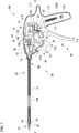
- Fig. 1 is a longitudinal cross-sectional view explaining a schematic configuration of a needle carrier according to the first embodiment when seen from a side view
- Fig. 2 is a perspective view explaining a schematic configuration in a state in which a pinching attachment is attached.
- Fig. 3A is a plan view explaining a schematic configuration in a state in which the pinching attachment is open
- Fig. 3B is a plan view explaining a schematic configuration in a state in which the pinching attachment is closed.
- reference sign 100 designates a needle carrier (a grasper)
- reference sign 10 designates a needle carrier body (a grasper main body)
- reference sign 20 designates a pinching attachment (a grasping member)
- reference sign 30 designates a pinching arm opening/closing drive portion (a first drive part)
- reference sign 40 designates a pinching arm pivotal drive portion (a second drive part).
- reference sign 21 designates a pair of pinching arm members (hereinafter, may be referred to as a pinching arm member)
- reference sign 22 designates a pinching portion
- reference sign 24 designates a pinching arm holding portion
- reference sign 20J designates a pivoting support shaft.
- reference sign O1 designates a first axis line about which the pinching arm member 21 is pivoted to be opened and closed
- reference sign O2 designates a second axis line about which the pinching arm member 21 is pivoted in a vertical tangential direction
- reference sign F designates a tip side
- reference sign R designates a base end side (a side of an operator).
- the needle carrier (the grasper) 100 includes the needle carrier body (the grasper main body) 10, the pinching attachment (the grasping member) 20, the pinching arm opening/closing drive portion (the first drive part) 30, and the pinching arm pivotal drive portion (the second drive part) 40.
- the needle carrier (the grasper) 100 is configured to handle a suturing needle (an object) in a surface in a vertical tangential direction (a longitudinal direction of the needle carrier 100) by pivoting the pinching attachment 20 around the second axis line O2 while pinching the suturing needle (the object) by pivoting the pinching arm member 21 around the first axis line O1.
- the needle carrier 100 may be used as a grasper configured to grasp biological tissue (including a part), a piercing instrument, an incision instrument, or the like, as an object, instead of the suturing needle.
- the needle carrier body (the grasper main body) 10 includes a casing 11, a base plate 12, a pipe attachment member 13, a protection pipe 14, a pipe attachment nut 15, and a pinching attachment metal fitting 16.
- the casing 11 includes a casing main body 111 to which a substantially rectangular parallelepiped portion is connected in a longitudinal direction below a substantially elongated cigar-shaped portion extending from the base end side R to the tip side F, a grip portion 112 formed integrally with the base end side R of a substantially rectangular parallelepiped portion of the casing main body 111, and an extension portion 113 disposed on the base end side R of the casing main body 111 and the grip portion 112 and extending toward the base end side R, and is formed in substantially a pistol shape.
- the casing 11 is configured to be split into left and right sides in a cross section shown in Fig. 1 , formed of a plastic resin having a substantially fixed thickness, and having a boss, an attachment hole, and the like, appropriately disposed thereon.
- the casing 11 has an internal space in which the casing main body 111 and the grip portion 112 are connected integrally, and the base plate 12, the pipe attachment member 13, the pinching arm opening/closing drive portion 30, the pinching arm pivotal drive portion 40, and the like, are disposed in the internal space.
- the left and right casings 11 are assembled integrally on the attachment portions 11A, 111B and 11C by attachment bolts.
- the attachment hole 11H is formed in a tip portion of the casing 11.
- intersection angle ⁇ may be arbitrarily set, and the intersection angle may be set to less than 45°.
- the base plate 12 has a rectangular portion formed in a substantially rectangular shape, and a guide groove 12G is formed from the base end side R toward the base end side F of the rectangular portion.
- the base plate 12 is constituted by a pair of left and right base plates, an interval adjustment member such as a sleeve or the like is sandwiched between the left and right base plates 12, and thus, the pinching arm opening/closing drive portion 30 and the pinching arm pivotal drive portion 40 are disposed at a fixed interval and sandwiched from left and right sides.
- a bracket extending toward the base end side R is connected to the base end side R of the substantially rectangular portion of the base plate 12 on the right side.
- the base plate 12 is attached to the attachment portion 11A formed on the bracket and the casing 11 in an attachment portion 12A and an attachment portion 12B disposed on the rectangular portion.
- the pipe attachment member 13 includes a skirt portion formed in a substantially truncated conical shape, and a multi-stage cylindrical portion extending from an apex portion of the skirt portion to the tip side F and having a pipe attachment hole formed therein to pass therethrough from the apex portion of the skirt portion in the longitudinal direction, and a male screw is formed on the tip side F of the multi-stage cylindrical portion.
- the pipe attachment member 13 can be attached to the tip side F of the casing 11 by correspondingly mounting the groove portion formed in the outer circumference of the base end side R of the multi-stage cylindrical portion on the edge portion of the attachment hole 11H of the casing 11.
- the protection pipe 14 is constituted by a cylindrical stainless steel pipe, and configured to accommodate a part of the pinching arm opening/closing drive portion (the first drive part) 30 and some of the components of the pinching arm pivotal drive portion (the second drive part) 40 therein.
- a guide member 14G such as a rod holder or the like be disposed in the protection pipe 14, and some of the components of the pinching arm opening/closing drive portion (the first drive part) 30 and the pinching arm pivotal drive portion (the second drive part) 40 be guided to the tip side F of the needle carrier body 10 from the casing 11.
- the protection pipe 14 is configured to prevent the pinching arm opening/closing drive portion 30 and the pinching arm pivotal drive portion 40 from coming in contact with the biological tissue and minimize occurrence of operation errors or damage to them due to an external force.
- a type and a position of the guide member 14G may be arbitrarily set, and for example, may be more appropriately disposed on both of the tip side F and the base end side R of the protection pipe 14.
- the pipe attachment nut 15 has a multi-stage hole, and a female screw corresponding to the male screw of the pipe attachment member 13 is formed on an inner circumferential surface of the base end side R of the multi-stage hole.
- the tip side F of the multi-stage hole is formed to have an inner diameter corresponding to an outer diameter of the protection pipe 14.
- the pipe attachment member 13 can be held in the protection pipe 14 and the protection pipe 14 can be accurately and reliably attached to the casing 11 by inserting the protection pipe 14 into the pipe attachment hole of the pipe attachment member 13 and mounting the pipe attachment nut 15 on the pipe attachment member 13.
- the pinching attachment metal fitting 16 includes a base plate wall portion 161 having a through-hole formed along the base end side R from the tip side F formed in a disk shape, a first support wall portion 162, a second support wall portion 163, and a cylindrical portion 164 connected to the base end side R of the base plate wall portion 161.
- the first support wall portion 162 is formed from a left end of the base plate wall portion 161 to the tip side F in the longitudinal direction.
- a pivoting shaft receiving hole 16H corresponding to the second axis line O2 is formed in the first support wall portion 162.
- the second support wall portion 163 is formed from a right end of the base plate wall portion 161 toward the tip side F in the longitudinal direction.
- the pivoting shaft receiving hole 16H corresponding to the second axis line O2 is formed in the second support wall portion 163.
- first support wall portion 162 and the second support wall portion 163 are formed to face each other, and a concave portion 16U is formed between the first support wall portion 162 and the second support wall portion 163.
- the pinching attachment (the grasping member) 20 includes the pinching arm member 21, the pinching arm holding portion 24, a pinching operation receiving lever 25, a return spring (a pinching arm returning means) 26, and the support shaft 20J.
- the pinching arm member 21 includes the left pinching arm member 21L and the right pinching arm member 21R.
- the left pinching arm member 21L and the right pinching arm member 21R are relatively pivotable around the first axis line O1.
- the pinching portion 22 is formed on the tip side F in the longitudinal direction.
- the pinching portion 22 includes a pinching protrusion (a pinching portion) 22L and a pinching protrusion (a pinching portion) 22R.
- the pinching protrusion 22L and the pinching protrusion 22R are configured such that the apex portion of the pinching protrusion 22L and the apex portion of the pinching protrusion 22R can face each other in the longitudinal direction (from the base end side R to the tip side F).
- a V-shaped pinching concave portion 23L (23) is formed between the pinching protrusion (the pinching portion) 22L and the pinching protrusion (the pinching portion) 22L, which are adjacent to each other, in a direction crossing (for example, perpendicular to) the longitudinal direction.
- a V-shaped pinching concave portion 23R (23) is formed between the pinching protrusion (the pinching portion) 22R and the pinching protrusion (the pinching portion) 22R, which are adjacent to each other, in a direction crossing (for example, perpendicular to) the longitudinal direction.
- the pinching protrusion 22L and the pinching protrusion 22R approach each other to pinch the object, and the pinching protrusion 22L and the pinching protrusion 22R are separated to release the object.
- the pinching operation receiving lever 25 is connected to the base end side R, and a pivoting shaft receiving hole (not shown) is formed between the left pinching arm member 21L and the pinching operation receiving lever 25 in the longitudinal direction.
- Fig. 4 is a perspective view of a pinching attachment, which is a view explaining a schematic configuration of an attachment relationship between the pinching attachment and the grasping member pivoting portion according to the first embodiment.
- the pinching arm holding portion 24 is disposed on the base end side R of the right pinching arm member 21R, and the right pinching arm member 21R and the pinching arm holding portion 24 are formed integrally with each other.
- a through-hole 24U is formed in the pinching arm holding portion 24 from the base end side R toward the tip side F, a left side when seen from the base end side R is open and the upper sidewall portion and the lower sidewall portion face each other to form a concave portion on the tip side F of the through-hole 24U, and the left pinching arm member 21L is accommodated in the concave portion.
- a through-hole into which the support shaft 20J corresponding to the first axis line O1 is fitted is formed in an upper sidewall portion and a lower sidewall of the pinching arm holding portion 24.
- the support shaft 20J is inserted into a pivoting shaft receiving hole (not shown) of the left pinching arm member 21L, and the left pinching arm member 21L is pivotably supported by the pinching arm holding portion 24 about the first axis line O1.
- the right pinching arm member 21R constitutes a fixed pinching arm member
- the left pinching arm member 21L constitutes a movable pinching arm member
- the pinching arm holding portion 24 has an attachment boss 24A formed on the base end side R.
- two flange portions (second engaging portions) 24B extending outward are formed in a part of the outer circumferential edge portion of the base end side R of the attachment boss 24A.
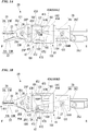
- Fig. 5A is a perspective view of a grasping member pivoting portion, which is a view explaining a schematic configuration of an attachment relationship between the pinching attachment and the grasping member pivoting portion.
- Fig. 5B is a cross-sectional view taken along arrow VB-VB in Fig. 5A when the grasping member pivoting portion is seen from the base end side in the attachment/detachment direction.
- a grasping member pivoting portion 47 includes a base plate portion 471 formed in a substantially flat plate shape, a first support wall portion 472 extending from a left end of the base plate portion 471 to the base end side R, a second support wall portion 473 extending from a right end of the base plate portion 471 to the base end side R, and a pivoting control concave portion 474 formed in the second support wall portion 473, and a pivoting shaft receiving hole 47H is coaxially formed in the first support wall portion 472 and the second support wall portion 473.
- a mounting hole 47A passing from the tip side F to the base end side R is formed in the base plate portion 471.
- first engaging portions 47B extending toward the inner circumferential side and corresponding to the two flange portions (the two second engaging portions) 24B are formed on the inner circumferential edge portion of the mounting hole 47A.
- the attachment boss 24A can be inserted into the mounting hole 47A of the grasping member pivoting portion 47 by being disposed such that the flange portion (the second engaging portion) 24B and the flange portion (the first engaging portion) 47B do not interfere with each other.
- the flange portion (the second engaging portion) 24B and the flange portion (the first engaging portion) 47B have screw-shaped tapered surfaces that are formed on surfaces thereof, which come in contact with each other.
- an axial force is generated in the attachment/detachment direction by tightening the flange portion (the second engaging portion) 24B and the flange portion (the first engaging portion) 47B to each other, and the flange portion (the second engaging portion) 24B and the flange portion (the first engaging portion) 47B are configured to be difficult to be removed by increasing a frictional force between the contact surfaces.
- the return spring (the pinching arm returning means) 26 is constituted by, for example, a tensile spring (a coil spring).
- a return spring 26 has a first end attached to a spring attachment pin 25P and a second end attached to a spring attachment pin 26P.
- the spring attachment pin 26P is fixed to the pinching arm holding portion 24 through the through-hole 24U.
- the first end of the return spring 26 is inserted into a spring insertion concave portion 25U formed in a side surface of the pinching operation receiving lever 25.
- the spring attachment pin 25P is attached to the return spring 26 via a pin accommodating hole 25H formed from an upper surface of the pinching operation receiving lever 25 toward the spring insertion concave portion 25U.
- the pinching operation receiving lever 25 is pulled toward the spring attachment pin 26P such that the left pinching arm member 21L is biased to a side where the pinching protrusion 22L and the pinching protrusion 22R shown by arrow R12 are separated (opened).
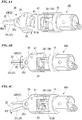
- Figs. 6A to 6C are perspective views explaining a schematic configuration of the mounting procedure of the pinching attachment of the first embodiment
- Fig. 6A is a view showing a state in which the pinching attachment is twisted to be inserted into the grasping member pivoting portion
- Fig. 6B is a view showing a state in which the pinching attachment is mounted on the grasping member pivoting portion
- Fig. 6C is a view showing a state in which the pair of pinching arm members are opened to engage the pinching operation receiving lever with the pinching arm operating lever.
- Figs. 7A and 7B are views explaining a schematic configuration of an attachment relationship between the pinching attachment and the grasping member pivoting portion
- Fig. 7A is a view showing a state in which the pinching attachment is twisted with respect to the grasping member pivoting portion, and a state in which the pinching attachment is mounted on the grasping member pivoting portion from the base end side in the attachment/detachment direction, respectively.
- the attachment/detachment direction indicates a direction shown by arrow A1 in Fig. 6A in which the pinching attachment 20 is inserted into the grasping member pivoting portion 47 and an opposite direction thereof
- the twisting direction indicates a direction shown by arrow A2 in Fig. 6B in which the inserted pinching attachment 20 is fastened to the grasping member pivoting portion 47 and an opposite direction thereof.
- the pinching operation receiving lever 25 is pivoted around the support shaft 20J in a direction shown by arrow R12A to abut the pinching arm operating lever 36, and the pinching operation receiving lever 25 can be operated by the pinching arm operating lever 36.
- Fig. 8 is a longitudinal cross-sectional view explaining a schematic configuration of the pinching arm opening/closing drive portion 30 according to the first embodiment when seen in a side view
- Figs. 9 and 10 are a side view and a perspective view explaining major portions of the pinching arm opening/closing drive portion 30 and the pinching arm pivotal drive portion 40 in detail.
- reference sign 31 designates a pinching operation lever (a pinching operation part)
- reference sign 32 designates a pinching operation transmission link
- reference sign 33 designates a guide member
- reference sign 34 designates a flexible transmission member
- reference sign 35 designates an axial dimension expansion/contraction spring
- reference sign 36 designates a pinching arm operating lever
- reference sign 37 designates a pinching operation lever return spring
- reference sign 38 designates a pinching operation lock mechanism.
- the pinching arm opening/closing drive portion (the first drive part) 30 has the pinching operation lever (the pinching operation part) 31 configured to cause the pair of pinching arm members 21 to perform a pinching operation, and a pinching operation transmission part configured to transmit the pinching operation from the pinching operation lever 31 to the pair of pinching arm members 21, and the pinching portion 22 is closed (pinched) by the pinching operation input to the pinching operation lever 31.
- the pinching arm opening/closing drive portion (the first drive part) 30 includes the pinching operation lever (the pinching operation part) 31, the pinching operation transmission link 32, the guide member 33, the flexible transmission member 34, the pinching arm operating lever 36, the pinching operation return spring 37, and the pinching operation lock mechanism 38.
- the pinching operation release mechanism is configured integrally with the pinching operation lock mechanism 38.
- the pinching operation lever (the pinching operation part) 31 the pinching operation transmission link 32, the guide member 33, the flexible transmission member 34, and the pinching arm operating lever 36 are connected in this order.
- the pinching operation transmission part includes the pinching operation transmission link 32, the guide member 33, the flexible transmission member 34, and the pinching arm operating lever 36.
- the pinching operation lever (the pinching operation part) 31 includes a pinching lever main body 311 and a return spring lever 312, and is formed in a substantially L shape.
- the pinching operation lever 31 is supported on the base plate 12 by a support shaft 31J, and pivotable around the support shaft 31J.
- an arc-shaped circumferential surface is formed in the vicinity of the support shaft 31J of the pinching lever main body 311, and a pivoting gear portion (a gear portion) 383S constituted by steps that is rapidly displaced toward the inner circumferential side when pivoted in the arrow T11 direction is formed on the arc-shaped circumferential surface.
- the pinching operation transmission link 32 is formed in, for example, an oval flat plate.
- the pinching operation transmission link 32 has a first end pivotably connected to the pinching operation lever 31 by a support pin 32J and a second end pivotably connected to the guide member 33 by a support pin 33J.
- the guide member 33 includes a guide member main body 331 and a bracket 332.
- a guide portion 33G is formed on the guide member main body 331 from the tip side F toward the base end side R, and the guide portion 33G is slidably disposed in the guide groove 12G of the base plate 12.
- the bracket 332 is connected to the pinching operation transmission link 32 by the support pin 33J, and the pinching operation input from the pinching operation lever 31 is transmitted to the guide member 33.
- the guide member main body 331 is slid along the guide groove 12G in an arrow Till direction by the pinching operation input from the pinching operation lever 31.
- the flexible transmission member 34 has a first end pivotably connected to a tip portion of the guide member 33 by a support pin 34J and a second end connected to the pinching arm operating lever 36. Then, the pinching operation input to the guide member 33 is transmitted to the pinching arm operating lever 36.
- the flexible transmission member 34 includes a first transmission part 341, a second transmission part 342, a third transmission part 343, a fourth transmission part 344, and the axial dimension expansion/contraction spring 35, and the axial dimension expansion/contraction spring 35 is disposed between the first transmission part 341 and the second transmission part 342.
- the second transmission part 342 and the third transmission part 343 are disposed on the same line.
- the flexible transmission member 34 is formed by a linear member such as a titanium alloy.
- the flexible transmission member 34 may be formed by a corrosion resistant metal having elasticity such as stainless steel (for example, SUS304/SUS304-CSP, SUS630, or the like) instead of the titanium alloy through rolling, heat treatment, or the like.
- a corrosion resistant metal having elasticity such as stainless steel (for example, SUS304/SUS304-CSP, SUS630, or the like) instead of the titanium alloy through rolling, heat treatment, or the like.
- the flexible transmission member 34 may be formed of a plurality of different materials.
- the first transmission part 341, the second transmission part 342, the third transmission part 343 and the fourth transmission part 344 are hard members, and a longitudinal dimension of the flexible transmission member 34 (a widthwise dimension of the first transmission part 341 and the fourth transmission part 344) is expanded and contracted by the axial dimension expansion/contraction spring 35.
- the first transmission part 341 has a first end connected to a tip portion of the guide member 33 by the support pin 34J and a second end joined to the base end side R of the axial dimension expansion/contraction spring 35.
- first transmission part 341, the axial dimension expansion/contraction spring 35, the second transmission part 342, the third transmission part 343 and the fourth transmission part 344 are joined to configure the flexible transmission member 34, for example, laser welding is appropriately used.
- the second transmission part 342 has a first end joined to the tip side F of the axial dimension expansion/contraction spring 35 and a second end joined to the third transmission part 343, and the pinching operation is transmitted from the axial dimension expansion/contraction spring 35 to the third transmission part 343.
- the third transmission part 343 is an elongated rod member, the first end is joined to the second transmission part 342, and the second end is joined to the fourth transmission part 344. Then, displacement of the second transmission part 342 is transmitted to the third transmission part 343.
- the fourth transmission part 344 has a first end side joined to the third transmission part 343, and a chevron clevis is formed on the first end side. Then, the chevron clevis is inserted into the pinching arm operating lever 36 and pivotably connected thereto by a support shaft 36J.
- the axial dimension expansion/contraction spring 35 includes a first end portion 351 disposed on the first end side, a second end portion 352 disposed on the second end side, a winding portion (a circumferential portion) 353 disposed between the first end portion 351 and the second end portion 352 and on which a linear member is wound (for example, one turn or more) to form a substantially circular shape when seen in a side view, and a direction change portion 354 configured to change a direction in which the second end portion 352 extends between the winding portion 353 and the second end portion 352.
- the axial dimension expansion/contraction spring 35 is formed by, for example, a titanium alloy linear member (for example, about ⁇ 1.5 to 2 mm).
- the first end side extends toward the base end side R and is connected to the first transmission part 341.
- the second end side is connected to the first end of the winding portion (the circumferential portion) 353.
- the second end portion 352 is disposed at a position offset from the first end portion 351 when seen along, for example, an axis line, and the first end side is connected to the winding portion (the circumferential portion) 353 via the direction change portion 354.
- the second end portion 352 extends toward a side opposite to the first end portion 351, and the second end side is connected to the second transmission part 342.
- the winding portion (the circumferential portion) 353 is formed by winding the titanium alloy linear member (for example, one turn or more).
- the direction change portion 354 is configured in, for example, a curved shape (or a turn shape), the second end portion 352 is offset from the first end portion 351 extending from the winding portion (the circumferential portion) 353 in a winding direction, and the first end portion 351 and the second end portion 352 extend in opposite directions.
- the number of turns of the winding portion 353 may be a plurality of times.
- the circular shape that forms the winding portion 353 is not limited to when seen from the side view, and may be disposed to circumferentially surround the winding portion when seen in a plan view.
- winding portion 353 is not limited to a true circular shape and may be an oval shape, or the like.
- the pinching arm operating lever 36 includes a pinching operation output lever 361 and an input lever 362, and a bearing hole (not shown) is formed between the pinching operation output lever 361 and the input lever 362.
- a U-shaped clevis is formed on the input lever 362, and a chevron clevis of the fourth transmission part 344 of the flexible transmission member 34 is mounted on the U-shaped clevis and pivotably connected thereto by the support shaft 36J.
- a bearing hole (not shown) formed in the pinching arm operating lever 36, a through-hole 164H formed in the cylindrical portion 164 of the pinching attachment metal fitting 16 and a hole (not shown) formed in the protection pipe 14 overlap each other and a support shaft 37 is fitted into these holes, and thus, the pinching arm operating lever 36 is configured to be pivotable around an axis line O3 parallel to the first axis line O1.
- the pinching operation return spring 37 is constituted by, for example, a coil spring, the first end is connected to the return spring lever 312 of the pinching operation lever 31 by a support pin 37J, and the second end is connected to an attachment boss 112A in the grip portion 112.
- the pinching operation lever 31 is configured to be biased in an orientation opposite to the arrow T11 direction.
- pinching operation return spring 37 for example, a spiral spring, a torsion spring, or the like, may be used.
- Fig. 11 is a schematic configuration view showing a schematic configuration of the pinching operation lock mechanism of the pinching arm opening/closing drive portion according to the first embodiment when seen in a side view.
- reference sign 381 designates a lock mechanism drive pin
- reference sign 382 designates a ratchet drive cam
- reference sign 383 designates a ratchet lever
- reference sign 384 designates a ratchet lever biasing spring.
- the pinching operation lock mechanism 38 includes the lock mechanism drive pin 381, the ratchet drive cam 382, the ratchet lever 383, and the ratchet lever biasing spring 384.
- the lock mechanism drive pin 381 is constituted by a pin standing on the pinching operation lever 31, and turns around the support shaft 31J together with pivotal movement of the pinching operation lever 31 by the pinching operation.
- the ratchet drive cam 382 is formed in a flat plate shape having a substantially pentagonal appearance, and includes a support shaft 382J standing upward from the vicinity of one vertical angle, a drive pin receiving concave portion 382U, and a ratchet locking protrusion 382C.
- the ratchet drive cam can pivot (swing) around the support shaft 382J.
- the drive pin receiving concave portion 382U is disposed at an opposite side of the support shaft 382J, constituted by a concave portion formed to have a width having a larger dimension than that of a diameter of the lock mechanism drive pin 381, and has a play with respect to the lock mechanism drive pin 381.
- the ratchet drive cam 382 is pivotable (swingable) around the support shaft 382J except when pressed against the lock mechanism drive pin 381.
- the ratchet locking protrusion 382C is disposed on the ratchet drive cam 382 on the side of the ratchet lever 383, and an apex portion is formed to protrude in a substantially semi-circular shape.
- the ratchet lever 383 is constituted by a substantially L-shaped flat plate, and includes a support shaft 383J standing from the vicinity of an end portion of one side of the L shape, a flat portion 383F formed on an edge portion of the ratchet drive cam 382 of the other side of the L shape, an arc-shaped ratchet locking concave portion 383U formed in the middle of the flat portion 383F, and a ratchet claw portion (a locking claw portion) 383T formed at a tip side of the other side of the L shape.
- the ratchet lever 383 is configured to pivot (swing) around the support shaft 383J.
- the ratchet claw portion (the locking claw portion) 383T is configured to correspond to the pivoting gear portion (the gear portion) 383S of the pinching operation lever 31.
- the pinching operation lever 31 is not pivoted in a direction corresponding to a tensile direction T37 of the pinching operation return spring 37 (in Fig. 11 , a direction shown by arrow T12). As a result, the pinching state (a closed state) of the pinching portion 22 is held.
- the pinching operation lever 31 is recovered in an arrow T12 direction while the pinching state (the closed state) of the pinching portion 22 is released.
- the ratchet lever biasing spring 384 is constituted by, for example, a torsion spring.
- the ratchet lever biasing spring 384 is configured to be supported by a support pin 384A axially supported by the support shaft 383J and standing from the base plate and a support pin 384B standing from the ratchet lever 383, and to bias the ratchet lever 383 such that the ratchet claw portion (the locking claw portion) 383T is disposed on the side of the pivoting gear portion (the gear portion) 383S.
- Figs. 12A and 12B are views explaining actions of the pinching arm opening/closing drive portion and the pinching operation lock mechanism according to the first embodiment
- Fig. 12A shows a state before the pinching operation is started
- Fig. 12B shows a state when the pinching operation is terminated.
- Fig. 13A is a schematic configuration view showing the axial dimension expansion/contraction spring in a state in which the pinching arm member is open
- Fig. 13B is a schematic configuration view showing the axial dimension expansion/contraction spring in a state in which the pinching arm member is closed.
- Figs. 14A and 14B are views explaining release of the pinching operation lock mechanism according to the first embodiment
- Fig. 14A is a schematic configuration view showing a state in which release of the pinching operation lock mechanism is started
- Fig. 14B is a schematic configuration view showing a state in which the pinching operation lock mechanism is released.
- the pinching operation lever 31 is pivoted in the arrow T12 direction by the tensile direction T37 of the pinching operation return spring 37 to return to an original position.
- Fig. 15 is a longitudinal cross-sectional view explaining a schematic configuration of the pinching arm pivotal drive portion according to the first embodiment when seen in a side view
- Fig. 16 is a schematic configuration view explaining an action of the pinching arm pivotal drive portion when seen in a side view.
- reference sign 40 designates a pinching arm pivotal drive portion (a second drive part)
- reference sign 41 designates a pivotal operation wheel (a pivotal operation part)
- reference sign 42 designates a pivotal operation transmission link
- reference sign 43 designates a pivoting control cam
- reference sign 44 designates a transmission link
- reference sign 45 designates a first transmission rod
- reference sign 46 designates a second transmission rod
- reference sign 47 designates a grasping member pivoting portion.
- the pinching arm pivotal drive portion (the second drive part) 40 includes, as shown in Figs. 15 , 7 and 8 , for example, the pivotal operation wheel (the pivotal operation part) 41, the pivotal operation transmission link 42, the pivoting control cam 43, the transmission link 44, the first transmission member 45, the second transmission member 46, and the grasping member pivoting portion 47 configured to pivot the pinching arm member 21 around the second axis line O2 using a pivotal operation.
- the pivotal operation wheel (the pivotal operation part) 41 includes a wheel main body portion 411 formed in an arc shape, and a lever portion 412 formed on a first end of the wheel main body portion 411.
- the pivotal operation wheel 41 is supported by a support shaft 41J and pivotable around the support shaft 41J.
- a finger receiving member is mounted on an outer circumference of the wheel main body portion 411 such that a finger is easily caught.
- the wheel main body portion 411 is configured to be pivoted around the support shaft 41J in directions of arrows T21 and T22 by the pivotal operation.
- the pivotal operation transmission link 42 is constituted by an elongated flat plate curved at a central portion having substantially a " ⁇ " shape.
- pivotal operation transmission link 42 is pivotably connected to an outer circumferential portion of the lever portion 412 of the pivotal operation wheel 41 around the support pin 42J by a support pin 42J.
- pivotal operation transmission link 42 is pivotably connected to an outer circumferential portion of the pivoting control cam 43 around the support shaft 43J by a support shaft 43J.
- the pivoting control cam 43 is formed in a substantially circular plate shape, and pivotably supported on the base plate 12 by a support shaft 430.
- the support shaft 43J, a support shaft 441J and a support shaft 442J are disposed on the outer circumferential portion.
- support shaft 441J and the support shaft 442J are disposed at an interval of about 90° with the support shaft 43J sandwiched therebetween in the circumferential direction.
- the pivoting control cam 43 is pivoted around the support shaft 430J by the pivotal operation input from the pivotal operation wheel 41 via the pivotal operation transmission link 42, and the pivotal operation is transmitted to the transmission link 44. Specifically, when the pivotal operation wheel 41 is pivoted in the arrow T21 direction, the pivoting control cam 43 is pivoted in an arrow T211 direction, and when the pivotal operation wheel 41 is pivoted in the arrow T22 direction, the pivoting control cam 43 is pivoted in an arrow T221 direction.
- the transmission link 44 includes a first transmission link 441 and a second transmission link 442.
- the first transmission link 441 and the second transmission link 442 are seen from a side view, the first transmission link 441 is disposed above the second transmission link 442.
- the first transmission link 441 is constituted by an oval flat plate.
- the first transmission link 441 has a first end pivotably connected to the pivoting control cam 43 by the support shaft 441J and a second end pivotably connected to the first transmission member 45 by a support shaft 45J.
- the first transmission link 441 transmits a pivotal operation from the pivoting control cam 43 to the first transmission member 45.
- the second transmission link 442 is constituted by an oval flat plate.
- the second transmission link 442 has a first end pivotably connected to the pivoting control cam 43 by the support shaft 442J and a second end pivotably connected to the second transmission member 46 by a support shaft 46J.
- the second transmission link 442 transmits a pivotal operation from the pivoting control cam 43 to the second transmission member 46.
- the first transmission member 45 includes a first member 451, a second member 452, a third member 453 and a fourth member 454, and the first member 451, the second member 452, the third member 453 and the fourth member 454 are disposed from the base end side R toward the tip side F in this order.
- the first member 451 has a first end pivotably connected to the first transmission link 441 by the support shaft 45J and a male screw is formed on an outer circumference of a second end (the tip side F).
- the third member 453 has a first end (the base end side R) having a male screw formed on an outer circumference thereof and a second end connected to the fourth member 454. Further, the male screw of the third member 453 is formed in an opposite direction (a reverse screw) of the male screw of the first member 451.
- the second member 452 is formed in, for example, a cylindrical shape, and constituted by a male screw of the first member 451 on an inner side, and a turnbuckle having a female screw corresponding to the male screw of the third member 453.
- the first member 451 and the third member 453 can approach or be separated from each other to adjust a length of the first transmission member 45.
- the second member 45 is the length adjustment member such as a turnbuckle or the like may be arbitrarily set, and may have a configuration in which a length adjustment function is not provided.
- the fourth member 454 includes, for example, a transmission pin portion 454J pivotably connected to the grasping member pivoting portion 47, and a pivotal operation transmitted from the third member 453 is transmitted to the grasping member pivoting portion 47.
- the transmission pin portion 454J is constituted by a needle bearing or the like elongated along the second axis line O2, and offset from a laterally central portion of the protection pipe 14 to be connected to the grasping member pivoting portion 47.
- the second transmission member 46 includes a first member 461, a second member 462, a third member 463 and a fourth member 464, and the first member 461, the second member 462, the third member 463 and the fourth member 464 are disposed from the base end side R toward the tip side F in this order.
- the first member 461 has a first end pivotably connected to the second transmission link 442 by the support shaft 46J and a second end (the tip side F) having a male screw formed on an outer circumference thereof.
- the third member 463 has a first end (the base end side R) having a male screw formed on an outer circumference thereof and a second end connected to the fourth member 464. Further, the male screw of the third member 463 is formed in an opposite direction (a reverse screw) of the male screw of the first member 461.
- the second member 462 is formed in, for example, a cylindrical shape, and constituted by the male screw of the first member 461 on an inner side and a turnbuckle having a female screw corresponding to the male screw of the third member 463.
- first member 461 and the third member 463 can approach or be separated from each other by pivoting the second member 462 to adjust a length of the second transmission member 46.
- the second member 46 is the length adjustment member such as a turnbuckle or the like can be arbitrarily set, and may have a configuration in which the length adjustment function is not provided.
- the fourth member 464 includes, for example, a transmission pin portion 454J pivotably connected to the grasping member pivoting portion 47, and a pivotal operation transmitted from the third member 463 is transmitted to the grasping member pivoting portion 47.
- the transmission pin portion 464J is constituted by a needle bearing or the like elongated along the second axis line O2, and offset from a laterally central portion of the protection pipe 14 to be connected to the grasping member pivoting portion 47.
- the grasping member pivoting portion 47 includes the base plate portion 471, the first support wall portion 472 extending from a left end of the base plate portion 471, the second support wall portion 473 extending from a right end of the base plate portion 471, and the pivoting control concave portion 474 formed in the second support wall portion 473, and the pivoting shaft receiving hole 47H is formed coaxially with the first support wall portion 472 and the second support wall portion 473.
- two pivoting control concave portions 474 are formed in an outer circumference of the second support wall portion 473.
- Cylindrical pins are joined to end portions of the transmission pin portion 454J of the fourth member 454 and the transmission pin portion 464J of the fourth member 464 on the tip side F in a direction perpendicular to major axes of the transmission pin portion 454J and the transmission pin portion 464J, and the pins are configured to engage with the pivoting control concave portion 474.
- a concave portion 47U in which the pinching arm operating lever 36 is disposed is formed between the first support wall portion 472 and the second support wall portion 473.
- the grasping member pivoting portion 47 is disposed in the concave portion 16U of the pinching attachment metal fitting 16, the pivoting shaft receiving hole 16H formed in the first support wall portion 162 of the pinching attachment metal fitting 16 and the pivoting shaft receiving hole 47H formed in the first support wall portion 472 of the grasping member pivoting portion 47 overlap each other such that a pivoting support shaft 47J is inserted therethrough, and thus, the pivoting support shaft 47J is pivotably connected to the pinching attachment metal fitting 16 around the second axis line O2.
- pivoting shaft receiving hole 16H formed in the second support wall portion 163 and the pivoting shaft receiving hole 47H formed in the second support wall portion 473 overlap each other such that the pivoting support shaft 47J is inserted therethrough, and thus, the pivoting support shaft 47J is pivotably connected to the pinching attachment metal fitting 16 around the second axis line O2.
- the grasping member pivoting portion 47 is pivoted such that the first transmission member 45 is moved in an arrow T222A direction, the second transmission member 46 is moved in an arrow T222B direction, and the pinching arm member 21 is pivoted in an arrow R22 direction.
- FIGs. 17A to 17D are views explaining an example of an action of the needle carrier according to the first embodiment
- Fig. 17A shows a state in which the suturing needle is pinched by the pinching arm member 21
- Fig. 17B shows a state in which the suturing needle is pierced into a first biological tissue
- Fig. 17C shows a state in which the first biological tissue and a second biological tissue are sutured
- Fig. 17D shows a state in which the suturing needle is changed after suturing.
- reference sign 110 designates a suturing needle
- reference sign 110T designates a suturing thread
- reference sign S1 designates a first biological tissue that is first pierced by the suturing needle 110
- reference sign S2 indicates a second biological tissue.
- first biological tissue S1 and the second biological tissue S2 correspond to, for example, a blood vessel and the like.
- the tip side of the suturing needle 110 is pinched again and the suturing needle 110 is pulled out of the second biological tissue S2, and the first biological tissue S1 and the second biological tissue S2 are connected by the suturing thread 110T.
- the pinching portion 22 can be closed to grasp the suturing needle 110.
- the pinching portion 22 can be pivoted around the second axis line O2 by the pinching arm pivotal drive portion (the second drive part) 40 to perform vertical handling of the needle (or change a posture of the object).
- the pinching arm opening/closing drive portion (the first drive part) 30 includes the axial dimension expansion/contraction spring 35 and the pair of pinching arm members 21 are biased toward a side at which the pinching portion 22 is closed by the axial dimension expansion/contraction spring 35 when the pinching operation is performed, occurrence of a play in the pinching portion 22 when the object such as a suturing needle or the like is pinched is minimized, and the object can be reliably pinched.
- the pinching operation is transmitted to the pinching portion 22 via the axial dimension expansion/contraction spring 35, even when a large load is applied to the pinching operation input part, the load is attenuated and transmitted to the pinching portion 22 without being directly transmitted, and thus, occurrence of damage to the suturing needle 110 can be minimized.
- the needle carrier 100 can be used for a long time while a decrease in reliability of the needle carrier 100 is minimized.
- the pinching operation displacement absorption means is constituted by the axial dimension expansion/contraction spring 35 disposed on the flexible transmission member 34, a pinching operation transmission force can be efficiently converted into a biasing force at a side where the pinching arm member 21 is closed by a simple structure.
- the suturing needle 110 can be easily and stably grasped.
- the suturing needle 110 can be stably grasped in a confined space, and handling of the needle can be efficiently and stably performed.
- the pinching attachment 20 of the first embodiment can be easily and efficiently attached to and detached from the needle carrier body 10.
- the pinching attachment 20 is disposable, and hygienic safety in surgery can be improved.
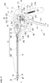
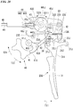
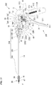
- Fig. 18 is a longitudinal cross-sectional view explaining a schematic configuration of a needle carrier according to the second embodiment when seen in a side view
- Fig. 19 is a longitudinal cross-sectional view explaining a schematic configuration of a pinching arm pivotal drive portion when seen in a side view
- Fig. 20 is a longitudinal cross-sectional view explaining a schematic configuration of a pinching arm opening/closing drive portion when seen in a side view
- Fig. 21 is a side view explaining major portions of the pinching arm opening/closing drive portion and the pinching arm pivotal drive portion in detail
- FIG. 22A is a schematic configuration view showing an S-shaped spring in a state in which the pinching arm member is open, which is a view explaining an action of the pinching arm opening/closing drive portion, and Fig. 22B is a schematic configuration view showing the S-shaped spring in a state in which the pinching arm member is closed.
- reference sign 200 designates a needle carrier (a grasper)
- reference sign 230 designates a pinching arm opening/closing drive portion (a first drive part)
- reference sign 234 designates a flexible transmission member
- reference sign 235 designates an S-shaped spring (an axial dimension expansion/contraction spring).
- the needle carrier (the grasper) 200 includes a needle carrier body (a grasper main body) 10, a pinching attachment (a grasping member) 20, the pinching arm opening/closing drive portion (the first drive part) 230 and a pinching arm pivotal drive portion (the second drive part) 40.
- the needle carrier (the grasper) 200 is configured such that the pinching arm member 21 is pivoted around the first axis line O1 to pinch the suturing needle (the object), and the pinching attachment 20 is pivoted around the second axis line O2 to enable handling of the suturing needle (the object) in a surface in a vertical tangential direction (a longitudinal direction of the needle carrier 200).
- the needle carrier body (the grasper main body) 10 the pinching attachment (the grasping member) 20 and the pinching arm pivotal drive portion (the second drive part) 40 are the same as those of the first embodiment, they are designated by the same reference signs and description thereof will be omitted.
- the needle carrier 200 may be used as a grasper configured to grasp biological tissue (including a part), a piercing instrument, an incision instrument, or the like, as an object instead of the suturing needle.
- the pinching arm opening/closing drive portion (the first drive part) 230 will be described with reference to Figs. 20 to 22B .
- Fig. 20 is a longitudinal cross-sectional view explaining a schematic configuration of the pinching arm opening/closing drive portion 230 according to the second embodiment when seen in a side view.
- the pinching arm opening/closing drive portion (the first drive part) 230 has the pinching operation lever (the pinching operation part) 31 configured to cause the pair of pinching arm members 21 to perform a pinching operation, and a pinching operation transmission part configured to transmit the pinching operation from the pinching operation lever 31 to the pair of pinching arm members 21, and the pinching portion 22 is closed (pinched) by the pinching operation input to the pinching operation lever 31.
- the pinching arm opening/closing drive portion (the first drive part) 230 includes the pinching operation lever (the pinching operation part) 31, the pinching operation transmission link 32, the guide member 33, the flexible transmission member 234, the pinching arm operating lever 36, the pinching operation return spring 37 and the pinching operation lock mechanism 38.
- the pinching operation lever (the pinching operation part) 31 the pinching operation transmission link 32, the guide member 33, the flexible transmission member 234 and the pinching arm operating lever 36 are connected in this order.
- the flexible transmission member 234 includes the first transmission part 341, the second transmission part 342, the third transmission part 343, the fourth transmission part 344 and the S-shaped spring (the axial dimension expansion/contraction spring) 235, and the S-shaped spring 235 is disposed between the first transmission part 341 and the second transmission part 342.
- a longitudinal dimension of the flexible transmission member 234 (a widthwise dimension of the first transmission part 341 and the fourth transmission part 344) is expanded or contracted by the S-shaped spring 235.
- first transmission part 341, the second transmission part 342, the third transmission part 343 and the fourth transmission part 344 are the same as those of the first embodiment, they are designated by the same reference signs and description thereof will be omitted.
- the S-shaped spring (the axial dimension expansion/contraction spring) 235 is constituted by a ribbon-shaped titanium alloy, and when seen in a side view, formed in an S shape having two curved portions that are curved in opposite directions.
- the S-shaped spring (the axial dimension expansion/contraction spring) 235 includes a first end portion 2351 disposed on a first end side, a second end portion 2352 disposed on a second end side, a first curved portion 2353 disposed between the first end portion 2351 and the second end portion 2352, and a second curved portion 2354.
- the first end portion 2351 has a first end side extending toward the base end side R and connected to the first transmission part 341.
- a second end side of the first end portion 2351 is connected to a first end side of the first curved portion 2353.
- the second end portion 2352 is disposed at a position offset with respect to the first end portion 2351, for example, when seen along the axis line, and the first end side is connected to the second end (the tip side F) of the second curved portion 2354.
- the second end portion 2352 extends toward a side opposite to the first end portion 2351 (the base end side R), and the second end side is connected to the second transmission part 342 disposed on the tip side F.
- the first curved portion 2353 is formed in a curved shape protruding toward the tip side F, and the first end side is connected to the first end portion 2351.
- the second curved portion 2354 is formed in a curved shape protruding toward the base end side R, and the second end side is connected to the second end portion 2352.
- the second end side of the first curved portion 2353 (the end portion on the side opposite to the first end portion 2351) and the second end side of the second curved portion 2354 (the end portion on the side opposite to the second end portion 2352) are coaxially connected to each other.
- first curved portion 2353 and the second curved portion 2354 are vertically arranged while protruding directions are opposite to each other and disposed in substantially an S shape.
- the first curved portion 2353 and the second curved portion 2354 are offset, for example, when the first end portion 2351 and the second end portion 2352 are seen in the axial direction, and the first end portion 2351 and the second end portion 2352 extend in opposite directions.
- the S-shaped spring (the axial dimension expansion/contraction spring) 235 is configured such that curvatures of the first curved portion 2353 and the second curved portion 2354 are decreased or increased when a load in an axial direction (a tensile direction, a compression direction) is applied between the first end portion 2351 and the second end portion 2352 according to the above-mentioned configuration.
- first curved portion 2353 and the second curved portion 2354 are not limited to the case in which they are curved when seen in a side view and may be disposed to be curved when seen in a plan view.
- Fig. 22A is a schematic configuration view showing an S-shaped spring in a state in which the pinching arm member is open
- Fig. 22B is a schematic configuration view showing the S-shaped spring in a state in which the pinching arm member is closed.
- the biasing force is transmitted to the pinching arm operating lever 36 via the third transmission part 343 and the fourth transmission part 344, and the object such as the suturing needle or the like can be grasped in a state in which the left pinching arm member 21L is closed.
- the curvatures of the first curved portion 2353 and the second curved portion 2354 are increased, as a result, even when an excessive load is applied between the first end portion 2351 and the second end portion 2352, displacement of the S-shaped spring 235 in the axial direction can be absorbed.
- the pinching portion 22 when the operator causes the pinching arm member 21 to perform the pinching operation using the pinching arm opening/closing drive portion (the first drive part) 230, the pinching portion 22 can be closed to grasp the suturing needle.
- the pinching portion 22 can be pivoted around the second axis line O2 by the pinching arm pivotal drive portion (the second drive part) 40 to perform vertical handling of the needle (or change the posture of the object).
- the pinching arm opening/closing drive portion (the first drive part) 230 includes the S-shaped spring 235 and the pinching operation is performed, since the pair of pinching arm members 21 are biased toward a side where the pinching portion 22 is closed by the S-shaped spring 235, occurrence of a play in the pinching portion 22 when the object such as the suturing needle or the like is pinched can be minimized to reliably perform the pinching.
- the pinching operation is transmitted to the pinching portion 22 via the S-shaped spring 235, even when a large load is applied to the pinching operation input part, the load is attenuated and transmitted to the pinching portion 22 without being directly transmitted thereto, and thus, occurrence of damage to the suturing needle 110 can be minimized.
- the large force is attenuated and transmitted to the pinching portion 22 via the pinching arm opening/closing drive portion (the first drive part) 230, occurrence of damage to the members that constitute the pinching arm opening/closing drive portion 230 can be minimized, and the needle carrier 200 can be used for a long time while a decrease in reliability of the needle carrier 200 is minimized.
- the pinching operation displacement absorption means is constituted by the S-shaped spring 235 disposed on the flexible transmission member 234, the pinching operation transmission force can be efficiently converted into a biasing force at the side where the pinching arm member 21 is closed by a simple structure.
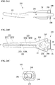
- Fig. 23 is a longitudinal cross-sectional view explaining a schematic configuration of the grasper according to the third embodiment of the present invention when seen in a side view.
- Figs. 23A to 23C are views explaining a schematic configuration of a forceps attachment
- Fig. 23A is a schematic configuration view showing the forceps attachment when seen in a side view
- Fig. 23B is a schematic configuration view when seen in a plan view
- Fig. 23C is a schematic configuration view when seen from a base end side.
- reference sign 300 designates a grasper
- reference sign 320 designates a forceps attachment (a grasping member).
- the grasper 300 includes a grasper main body 10, the forceps attachment (the pinching attachment, the grasping member) 320, the pinching arm opening/closing drive portion (the first drive part) 30 and the pinching arm pivotal drive portion (the second drive part) 40.
- the grasper 300 according to the third embodiment is distinguished from the needle carrier 100 according to the first embodiment in that the forceps attachment 320 is provided instead of the pinching attachment (the grasping member) 20 and the others are the same as those of the first embodiment, description thereof will be omitted.
- the forceps attachment (the pinching attachment, the grasping member) 320 includes a pinching arm member 321, the pinching arm holding portion 24, the pinching operation receiving lever 25, the return spring (the pinching arm returning means) 26 and the support shaft 20J.
- the pinching arm member 321 includes a left pinching arm member 321L and a right pinching arm member 321R.
- the pinching arm member 321 is tapered from the base end side R toward the tip side F and has a curved portion that is slightly curved upward.
- the entire length (a dimension in a longitudinal direction) of the pinching arm member 321 is, for example, 30 mm.
- a dimension from the tip of the left pinching arm member 321 to the first axis line O1 (a center of the support shaft 20J) is set to, for example, 22 mm.
- the pinching operation receiving lever 25 is connected to the base end side R, and a pivoting shaft receiving hole (not shown) is formed between the left pinching arm member 321L and the pinching operation receiving lever 25 in the longitudinal direction.
- the right pinching arm member 321R constitutes a fixed pinching arm member
- the left pinching arm member 321L constitutes a movable pinching arm member
- the left pinching arm member 321L and the right pinching arm member 321R are relatively pivotable around the first axis line O1.
- the pinching arm member 321 has a pinching protrusion 322 formed on the tip side F in the longitudinal direction.
- the pinching protrusion 322 includes the pinching protrusion (the pinching portion) 322L and the pinching protrusion (the pinching portion) 322R.
- the pinching protrusion 322L and the pinching protrusion 322R are alternately differently formed in the longitudinal direction (from the base end side R to the tip side F).
- the pinching protrusion 322L and the pinching protrusion 322R approach each other to pinch the object, and the pinching protrusion 322L and the pinching protrusion 322R are separated from each other to release the object.
- a V-shaped pinching concave portion 323L (323) is formed between the pinching protrusion (the pinching portion) 322L and the pinching protrusion (the pinching portion) 322L, which are adjacent to each other, for example, in a direction crossing (for example, perpendicular to) the longitudinal direction.
- a V-shaped pinching concave portion 323R (323) is formed between the pinching protrusion (the pinching portion) 322R and the pinching protrusion (the pinching portion) 322R, which are adjacent to each other, for example, in a direction crossing (for example, perpendicular to) the longitudinal direction.
- the pinching concave portions 323L and 323R are formed complementary to the pinching protrusions 322L and 322R (323).
- the forceps attachment 320 may be configured not to include the pinching protrusion 322 or the pinching concave portion 323.
- the configuration and the dimension of the forceps attachment (the pinching attachment) 320 may be arbitrarily set.
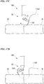
- Figs. 25A and 25B is a view explaining an example of an action of the grasper 300 to which the forceps attachment 320 according to the third embodiment is applied, for example, a conceptual view when a posture of a blood vessel Y3 disposed at a back side of biological tissues Y1 and Y2 is changed and treated in the abdominal cavity.
- reference sign 120 designates a trocar configured to insert the grasper 300 into the abdominal cavity in an abdominal cavity surgery.
- the pinching arm member 321 of the forceps attachment 320 is curved toward the tip side, for example, a part of a living body such as the blood vessel Y3 or the like, or a grasping object of biological tissue can be easily grasped.
- a position or a posture of the grasping object of the blood vessel Y3 can be easily and efficiently changed in a confined space.
- the grasper 300 for example, it is possible to prevent a grasping force when the biological tissue such as the blood vessel Y3 or the like is grasped from becoming too large, and it is possible to prevent the blood vessel Y3 or the like from being damaged.
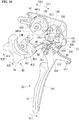
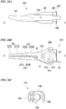
- Figs. 26A to 26C are views explaining a schematic configuration of the forceps attachment according to the fourth embodiment of the present invention
- Fig. 26A is a schematic configuration view of the forceps attachment when seen in a side view
- Fig. 26B is a schematic configuration view when seen in a plan view
- Fig. 26C is a schematic configuration view when seen from a base end side.
- reference sign 420 shows a forceps attachment (a grasping member).
- the forceps attachment (the pinching attachment, the grasping member) 420 includes a pinching arm member 421, a pinching arm holding portion 24, a pinching operation receiving lever 25, a return spring (a pinching arm returning means) 26 and a support shaft 20J.
- the pinching arm member 421 includes, for example, a left pinching arm member 421L and a right pinching arm member 421R.
- the pinching arm member 421 is tapered from the base end side R toward the tip side F, and becomes a curved portion having a larger curvature than that of the pinching arm member 321 according to the third embodiment.
- the entire length (a dimension in a longitudinal direction) of the pinching arm member 421 is formed as, for example, 23.4 mm.
- a dimension from the tip of the left pinching arm member 421 to the first axis line O1 (the center of the support shaft 20J) is set to, for example, 15.4 mm.
- a pinching protrusion 422 (422L, 422R) and a pinching concave portion 423 (423L, 423R) are formed on the pinching arm member 421 (421L, 421R).
- pinching protrusion 422 (422L, 422R) and the pinching concave portion 423 (423L, 423R) are the same as the pinching protrusion 322 (322L, 322R) and the pinching concave portion 323 (323L, 323R) according to the third embodiment, description thereof will be omitted.
- the configuration and the dimension of the forceps attachment (the pinching attachment) 420 can be arbitrarily set.
- the configuration of the pinching arm opening/closing drive portion 30 or 230 may be arbitrarily set, and a configuration in which the pinching attachment (the pinching member) 20 or the forceps attachment (the pinching member) 320 (420) is pinched by a first drive part having another configuration may be provided.
- the configuration of the pinching operation part may be arbitrarily set, and the pinching operation part may be constituted by a lever or the like instead of the pivotal operation wheel.
- the flexible transmission member 34 or 234 is formed of a titanium alloy
- the configuration and the material of the flexible transmission member 34 or 234 may be appropriately set, and for example, the member may be formed of a material other than the titanium alloy.
- the configuration and the disposed position of the pinching operation displacement absorption means may be arbitrarily set, and for example, it may be disposed separately from the flexible transmission member 34 or 235.
- the pinching operation displacement absorption means is constituted by the axial dimension expansion/contraction spring 35 including the winding portion (the circumferential portion) 353 and the S-shaped spring 235
- another type of an axial dimension expansion/contraction spring constituted by an air spring or a spiral spring may be applied thereto.
- the needle carrier 100 or 200 and the grasper 300 includes the pinching operation lock mechanism 38 and the pinching state of the pinching arm member 21 may be locked and released by the pinching operation lock mechanism 38
- whether the pinching arm lock mechanism38 is provided may be arbitrarily set, and the pinching operation lock mechanism 38 may be configured to only lock the pinching state.
- the configuration of the pinching operation lock mechanism may be appropriately set.
- the pinching arm member 21 may be configured to be stopped at a plurality of positions.
- the pinching arm pivotal drive portion (the second drive part) 40 includes the pivotal operation wheel (the pinching operation input part) 41, the pivotal operation transmission link 42, the pivoting control cam 43, the transmission link 44, the first transmission member 45, the second transmission member 46 and the grasping member pivoting portion 47 has been described in the above-mentioned embodiments, for example, a configuration in which a pivotal operation is transmitted from the pivotal operation wheel (the pinching operation input part) 41 to the grasping member pivoting portion 47 may be arbitrarily set, and a configuration in which the grasping member pivoting portion is directly pivoted by the pivotal operation part without including the pivotal operation transmission part may be provided.
- the configurations of the pivotal operation part and the grasping member pivoting portion may be arbitrarily set.
- the needle carrier 100 or 200 and the grasper 300 includes the pinching arm opening/closing drive portion (the first drive part) 30 or 230 and the pinching arm pivotal drive portion (the second drive part) 40 has been described in the above-mentioned embodiments, for example, a configuration in which only the pinching arm opening/closing drive portion (the first drive part) is provided and the grasping member (the pinching attachment, the forceps attachment, or the like) is pinched by the pinching arm opening/closing drive portion without a pivotal operation may be provided.
- the pinching attachment 20, 320 or 420 is configured such that the pinching member is detachable from the pinching arm opening/closing drive portion (the first drive part) 30 or 230 and the pinching arm pivotal drive portion (the second drive part) 40 has been described in the above-mentioned embodiments, a configuration in which the pinching member is fixed to the pinching arm opening/closing drive portion 30 or 230 or the pinching arm pivotal drive portion 40 may be provided.
- the configuration of the pinching attachment may be arbitrarily set.
- the pinching attachment 20 or the forceps attachment 320 or 420 may include the grasping member pivoting portion 47 or may have an arbitrary attachment relationship.
- a needle carrier and a pinching attachment of the present invention since they can be easily and efficiently operated by an operator, reliability of a pinching operation when the object is pinched can be improved, and the operation can be easily and efficiently performed, they are industrially applicable.
Landscapes
- Health & Medical Sciences (AREA)
- Life Sciences & Earth Sciences (AREA)
- Surgery (AREA)
- Molecular Biology (AREA)
- Engineering & Computer Science (AREA)
- Biomedical Technology (AREA)
- Heart & Thoracic Surgery (AREA)
- Medical Informatics (AREA)
- Nuclear Medicine, Radiotherapy & Molecular Imaging (AREA)
- Animal Behavior & Ethology (AREA)
- General Health & Medical Sciences (AREA)
- Public Health (AREA)
- Veterinary Medicine (AREA)
- Ophthalmology & Optometry (AREA)
- Surgical Instruments (AREA)
- Manipulator (AREA)
Applications Claiming Priority (2)
| Application Number | Priority Date | Filing Date | Title |
|---|---|---|---|
| JP2018157545 | 2018-08-24 | ||
| PCT/JP2019/033058 WO2020040295A1 (ja) | 2018-08-24 | 2019-08-23 | 把持器、持針器、挟持アタッチメント |
Publications (2)
| Publication Number | Publication Date |
|---|---|
| EP3841990A1 true EP3841990A1 (de) | 2021-06-30 |
| EP3841990A4 EP3841990A4 (de) | 2022-11-09 |
Family
ID=69593181
Family Applications (1)
| Application Number | Title | Priority Date | Filing Date |
|---|---|---|---|
| EP19852592.5A Withdrawn EP3841990A4 (de) | 2018-08-24 | 2019-08-23 | Greifer, nadelträger und klemmaufsatz |
Country Status (6)
| Country | Link |
|---|---|
| US (1) | US20210290224A1 (de) |
| EP (1) | EP3841990A4 (de) |
| JP (1) | JP7583388B2 (de) |
| KR (1) | KR20210047871A (de) |
| CN (1) | CN112638292A (de) |
| WO (1) | WO2020040295A1 (de) |
Families Citing this family (8)
| Publication number | Priority date | Publication date | Assignee | Title |
|---|---|---|---|---|
| DE102021127877A1 (de) | 2021-10-26 | 2023-04-27 | Karl Storz Se & Co. Kg | Handhabungsvorrichtung für die Handhabung medizinischer und/oder chirurgischer Instrumente sowie medizinisches System mit einer Handhabungsvorrichtung |
| JP2023124330A (ja) * | 2022-02-25 | 2023-09-06 | 株式会社産業情報総合研究所 | 把持器 |
| US12433624B2 (en) | 2022-05-11 | 2025-10-07 | Verb Surgical Inc. | Actuation combiner mechanism for a surgical tool |
| US12268406B2 (en) | 2022-05-11 | 2025-04-08 | Verb Surgical Inc. | Actuation combiner mechanism and motor for a surgical tool |
| CN119173209A (zh) * | 2022-05-11 | 2024-12-20 | 威博外科公司 | 用于外科工具的致动组合器机构 |
| KR102879279B1 (ko) * | 2023-01-11 | 2025-10-31 | 주식회사 제일메디칼코퍼레이션 | 골 접합용 스태플 홀더 |
| CN116492059B (zh) * | 2023-05-06 | 2025-12-16 | 南昌华安众辉健康科技股份有限公司 | 具有尖端的多自由度机械臂的控制机构及具有尖端的器械 |
| CN119564306B (zh) * | 2024-12-17 | 2025-05-30 | 常州维卓致远医疗科技发展有限公司 | 一种穿刺器械定位装置 |
Family Cites Families (14)
| Publication number | Priority date | Publication date | Assignee | Title |
|---|---|---|---|---|
| US5114407A (en) * | 1990-08-30 | 1992-05-19 | Ethicon, Inc. | Safety mechanism for trocar |
| US5507773A (en) * | 1994-02-18 | 1996-04-16 | Ethicon Endo-Surgery | Cable-actuated jaw assembly for surgical instruments |
| JPH0838492A (ja) | 1994-07-29 | 1996-02-13 | Olympus Optical Co Ltd | 手術用鉗子 |
| US7686826B2 (en) | 2003-10-30 | 2010-03-30 | Cambridge Endoscopic Devices, Inc. | Surgical instrument |
| WO2007043183A1 (ja) * | 2005-10-14 | 2007-04-19 | Pascal Engineering Corporation | スイング式クランプ装置 |
| JP5364255B2 (ja) * | 2007-10-31 | 2013-12-11 | テルモ株式会社 | 医療用マニピュレータ |
| GB201119897D0 (en) * | 2011-11-18 | 2011-12-28 | Gyrus Medical Ltd | Electrosurgical instrument |
| JP4972224B1 (ja) | 2011-11-25 | 2012-07-11 | 泉工医科工業株式会社 | 把持器、持針器及びアタッチメント |
| JP2015080556A (ja) * | 2013-10-22 | 2015-04-27 | 株式会社スズキプレシオン | 高機能手術デバイス |
| JP6045755B2 (ja) * | 2014-07-03 | 2016-12-14 | オリンパス株式会社 | 縫合持針器及び内視鏡システム |
| EP4520287A3 (de) * | 2015-04-13 | 2025-03-26 | Levita Magnetics International Corp. | Zange mit magnetisch gesteuerter positionierung |
| WO2017068074A1 (en) * | 2015-10-20 | 2017-04-27 | Lumendi Ltd. | Medical instruments for performing minimally-invasive procedures |
| JP6622151B2 (ja) | 2016-06-29 | 2019-12-18 | 株式会社産業情報総合研究所 | 把持器、持針器及びアタッチメント |
| FR3065296B1 (fr) | 2017-02-17 | 2020-08-28 | Valeo Vision | Dispositif de communication, notamment pour vehicules automobiles |
-
2019
- 2019-08-23 US US17/250,588 patent/US20210290224A1/en not_active Abandoned
- 2019-08-23 KR KR1020217004631A patent/KR20210047871A/ko not_active Ceased
- 2019-08-23 JP JP2020538490A patent/JP7583388B2/ja active Active
- 2019-08-23 CN CN201980054918.5A patent/CN112638292A/zh active Pending
- 2019-08-23 EP EP19852592.5A patent/EP3841990A4/de not_active Withdrawn
- 2019-08-23 WO PCT/JP2019/033058 patent/WO2020040295A1/ja not_active Ceased
Also Published As
| Publication number | Publication date |
|---|---|
| US20210290224A1 (en) | 2021-09-23 |
| CN112638292A (zh) | 2021-04-09 |
| JP7583388B2 (ja) | 2024-11-14 |
| KR20210047871A (ko) | 2021-04-30 |
| JPWO2020040295A1 (ja) | 2021-08-12 |
| WO2020040295A1 (ja) | 2020-02-27 |
| EP3841990A4 (de) | 2022-11-09 |
Similar Documents
| Publication | Publication Date | Title |
|---|---|---|
| EP3841990A1 (de) | Greifer, nadelträger und klemmaufsatz | |
| US6077287A (en) | Surgical instrument | |
| CA1240581A (en) | Surgical clip and forceps for clamping the same | |
| US9038880B1 (en) | Articulated surgical instrument | |
| US10646228B2 (en) | Endoscopic clip device and clip | |
| JP3729861B2 (ja) | 傷口閉鎖デバイス | |
| JP5165673B2 (ja) | 内視鏡装置 | |
| JP7209012B2 (ja) | クリップユニットおよび内視鏡クリップ | |
| WO2004089225A1 (en) | An improved circular stapler | |
| US20130317291A1 (en) | Treatment system and endoscope system | |
| WO2014181678A1 (ja) | 内視鏡処置具 | |
| WO2014181675A1 (ja) | クリップユニット | |
| JP6709419B2 (ja) | 縫合針 | |
| EP3431015A2 (de) | Nahtmagazin für chirurgisches nahtführungsinstrument | |
| US12446878B2 (en) | Multi-processing device for an endoscope and use method thereof | |
| JP6622151B2 (ja) | 把持器、持針器及びアタッチメント | |
| EP4397253A1 (de) | Klammerinstrument | |
| WO2016147464A1 (ja) | 縫合器 | |
| WO2020157855A1 (ja) | クリップカートリッジ、医療機器、および医療機器の装着方法 | |
| WO2020136826A1 (ja) | 医療機器、および医療機器の装着方法 | |
| WO2025095101A1 (ja) | 縫合器 | |
| US20210186546A1 (en) | Treatment device | |
| US12508017B2 (en) | Surgical guidewire device and suture fixation system | |
| US10729425B2 (en) | Suture device | |
| EP3643251B1 (de) | Nahtvorrichtung |
Legal Events
| Date | Code | Title | Description |
|---|---|---|---|
| STAA | Information on the status of an ep patent application or granted ep patent |
Free format text: STATUS: THE INTERNATIONAL PUBLICATION HAS BEEN MADE |
|
| PUAI | Public reference made under article 153(3) epc to a published international application that has entered the european phase |
Free format text: ORIGINAL CODE: 0009012 |
|
| STAA | Information on the status of an ep patent application or granted ep patent |
Free format text: STATUS: REQUEST FOR EXAMINATION WAS MADE |
|
| 17P | Request for examination filed |
Effective date: 20210205 |
|
| AK | Designated contracting states |
Kind code of ref document: A1 Designated state(s): AL AT BE BG CH CY CZ DE DK EE ES FI FR GB GR HR HU IE IS IT LI LT LU LV MC MK MT NL NO PL PT RO RS SE SI SK SM TR |
|
| DAV | Request for validation of the european patent (deleted) | ||
| DAX | Request for extension of the european patent (deleted) | ||
| RIC1 | Information provided on ipc code assigned before grant |
Ipc: A61B 17/062 20060101ALI20220628BHEP Ipc: A61B 17/29 20060101AFI20220628BHEP |
|
| A4 | Supplementary search report drawn up and despatched |
Effective date: 20221011 |
|
| RIC1 | Information provided on ipc code assigned before grant |
Ipc: A61B 17/062 20060101ALI20221005BHEP Ipc: A61B 17/29 20060101AFI20221005BHEP |
|
| STAA | Information on the status of an ep patent application or granted ep patent |
Free format text: STATUS: THE APPLICATION HAS BEEN WITHDRAWN |
|
| 18W | Application withdrawn |
Effective date: 20240530 |