EP3839331A1 - Kraftfahrzeugleuchtmodul mit zwei lichtquellen - Google Patents
Kraftfahrzeugleuchtmodul mit zwei lichtquellen Download PDFInfo
- Publication number
- EP3839331A1 EP3839331A1 EP20214784.9A EP20214784A EP3839331A1 EP 3839331 A1 EP3839331 A1 EP 3839331A1 EP 20214784 A EP20214784 A EP 20214784A EP 3839331 A1 EP3839331 A1 EP 3839331A1
- Authority
- EP
- European Patent Office
- Prior art keywords
- light
- printed circuit
- circuit board
- light source
- module
- Prior art date
- Legal status (The legal status is an assumption and is not a legal conclusion. Google has not performed a legal analysis and makes no representation as to the accuracy of the status listed.)
- Granted
Links
- 230000001105 regulatory effect Effects 0.000 claims description 14
- 239000004065 semiconductor Substances 0.000 claims description 8
- 230000003287 optical effect Effects 0.000 claims description 7
- 239000002184 metal Substances 0.000 description 11
- 230000001276 controlling effect Effects 0.000 description 3
- 230000008878 coupling Effects 0.000 description 2
- 238000010168 coupling process Methods 0.000 description 2
- 238000005859 coupling reaction Methods 0.000 description 2
- 230000011664 signaling Effects 0.000 description 2
- 229910000679 solder Inorganic materials 0.000 description 2
- 230000000295 complement effect Effects 0.000 description 1
- 230000001902 propagating effect Effects 0.000 description 1
- 239000000758 substrate Substances 0.000 description 1
Images

Classifications
-
- F—MECHANICAL ENGINEERING; LIGHTING; HEATING; WEAPONS; BLASTING
- F21—LIGHTING
- F21S—NON-PORTABLE LIGHTING DEVICES; SYSTEMS THEREOF; VEHICLE LIGHTING DEVICES SPECIALLY ADAPTED FOR VEHICLE EXTERIORS
- F21S45/00—Arrangements within vehicle lighting devices specially adapted for vehicle exteriors, for purposes other than emission or distribution of light
- F21S45/40—Cooling of lighting devices
- F21S45/47—Passive cooling, e.g. using fins, thermal conductive elements or openings
-
- B—PERFORMING OPERATIONS; TRANSPORTING
- B60—VEHICLES IN GENERAL
- B60Q—ARRANGEMENT OF SIGNALLING OR LIGHTING DEVICES, THE MOUNTING OR SUPPORTING THEREOF OR CIRCUITS THEREFOR, FOR VEHICLES IN GENERAL
- B60Q1/00—Arrangement of optical signalling or lighting devices, the mounting or supporting thereof or circuits therefor
- B60Q1/26—Arrangement of optical signalling or lighting devices, the mounting or supporting thereof or circuits therefor the devices being primarily intended to indicate the vehicle, or parts thereof, or to give signals, to other traffic
- B60Q1/2607—Arrangement of optical signalling or lighting devices, the mounting or supporting thereof or circuits therefor the devices being primarily intended to indicate the vehicle, or parts thereof, or to give signals, to other traffic comprising at least two indicating lamps
-
- F—MECHANICAL ENGINEERING; LIGHTING; HEATING; WEAPONS; BLASTING
- F21—LIGHTING
- F21S—NON-PORTABLE LIGHTING DEVICES; SYSTEMS THEREOF; VEHICLE LIGHTING DEVICES SPECIALLY ADAPTED FOR VEHICLE EXTERIORS
- F21S43/00—Signalling devices specially adapted for vehicle exteriors, e.g. brake lamps, direction indicator lights or reversing lights
- F21S43/10—Signalling devices specially adapted for vehicle exteriors, e.g. brake lamps, direction indicator lights or reversing lights characterised by the light source
- F21S43/13—Signalling devices specially adapted for vehicle exteriors, e.g. brake lamps, direction indicator lights or reversing lights characterised by the light source characterised by the type of light source
- F21S43/14—Light emitting diodes [LED]
-
- F—MECHANICAL ENGINEERING; LIGHTING; HEATING; WEAPONS; BLASTING
- F21—LIGHTING
- F21S—NON-PORTABLE LIGHTING DEVICES; SYSTEMS THEREOF; VEHICLE LIGHTING DEVICES SPECIALLY ADAPTED FOR VEHICLE EXTERIORS
- F21S43/00—Signalling devices specially adapted for vehicle exteriors, e.g. brake lamps, direction indicator lights or reversing lights
- F21S43/10—Signalling devices specially adapted for vehicle exteriors, e.g. brake lamps, direction indicator lights or reversing lights characterised by the light source
- F21S43/19—Attachment of light sources or lamp holders
- F21S43/195—Details of lamp holders, terminals or connectors
-
- F—MECHANICAL ENGINEERING; LIGHTING; HEATING; WEAPONS; BLASTING
- F21—LIGHTING
- F21S—NON-PORTABLE LIGHTING DEVICES; SYSTEMS THEREOF; VEHICLE LIGHTING DEVICES SPECIALLY ADAPTED FOR VEHICLE EXTERIORS
- F21S43/00—Signalling devices specially adapted for vehicle exteriors, e.g. brake lamps, direction indicator lights or reversing lights
- F21S43/20—Signalling devices specially adapted for vehicle exteriors, e.g. brake lamps, direction indicator lights or reversing lights characterised by refractors, transparent cover plates, light guides or filters
-
- B—PERFORMING OPERATIONS; TRANSPORTING
- B60—VEHICLES IN GENERAL
- B60Q—ARRANGEMENT OF SIGNALLING OR LIGHTING DEVICES, THE MOUNTING OR SUPPORTING THEREOF OR CIRCUITS THEREFOR, FOR VEHICLES IN GENERAL
- B60Q2400/00—Special features or arrangements of exterior signal lamps for vehicles
- B60Q2400/20—Multi-color single source or LED matrix, e.g. yellow blinker and red brake lamp generated by single lamp
-
- B—PERFORMING OPERATIONS; TRANSPORTING
- B60—VEHICLES IN GENERAL
- B60Q—ARRANGEMENT OF SIGNALLING OR LIGHTING DEVICES, THE MOUNTING OR SUPPORTING THEREOF OR CIRCUITS THEREFOR, FOR VEHICLES IN GENERAL
- B60Q2400/00—Special features or arrangements of exterior signal lamps for vehicles
- B60Q2400/30—Daytime running lights [DRL], e.g. circuits or arrangements therefor
-
- F—MECHANICAL ENGINEERING; LIGHTING; HEATING; WEAPONS; BLASTING
- F21—LIGHTING
- F21W—INDEXING SCHEME ASSOCIATED WITH SUBCLASSES F21K, F21L, F21S and F21V, RELATING TO USES OR APPLICATIONS OF LIGHTING DEVICES OR SYSTEMS
- F21W2103/00—Exterior vehicle lighting devices for signalling purposes
- F21W2103/20—Direction indicator lights
-
- F—MECHANICAL ENGINEERING; LIGHTING; HEATING; WEAPONS; BLASTING
- F21—LIGHTING
- F21W—INDEXING SCHEME ASSOCIATED WITH SUBCLASSES F21K, F21L, F21S and F21V, RELATING TO USES OR APPLICATIONS OF LIGHTING DEVICES OR SYSTEMS
- F21W2103/00—Exterior vehicle lighting devices for signalling purposes
- F21W2103/55—Daytime running lights [DRL]
Definitions
- the invention relates to the field of lighting and light signaling of motor vehicles. More specifically, the invention relates to a motor vehicle light module comprising at least two light sources.
- the document EP 2 161 494 describes for example a light module in which a first light source, associated with a daytime running light function, and a second light source, associated with a direction indicator function, are mounted on the same printed circuit board, facing vis-à-vis the entry surface of a single light guide so that the daytime running light and direction indicator functions are emitted from the same exit surface of this light guide.
- the invention relates to a light module of a motor vehicle, comprising a first light source associated with at least one first predetermined light function and a second light source associated with at least one second predetermined light function, in which the first light source is mounted on a first printed circuit board and the second light source is mounted on a second printed circuit board separate from the first printed circuit board, characterized in that it comprises a connector arranged to receive a power supply intended for the power supply of the first and / or second light sources for the realization of the first and / or second predetermined light functions, the connector being mounted on the first card of printed circuit board and the first printed circuit board being electrically connected to the second printed circuit board by a conductive member soldered to each of the first and second printed circuit boards.
- the invention thus proposes an alternative to known solutions, in that the first light source and the second light source are mounted on separate printed circuit boards. Furthermore, according to the invention, a single connector is employed to receive a power supply for the two light sources, this power supply being transmitted to the second light source from the first printed circuit board via the conductive element.
- the term “light source associated with a predetermined light function” is understood to mean the fact that the predetermined light function is produced from the light emitted by the light source when it is supplied by an electrical supply, alone or in combination with light. emitted by another light source, directly or after deflection by an optical device.
- the first printed circuit board and the second printed circuit board are arranged so that said electric power supply received by said connector can be transmitted to the second light source, via the conductive element.
- the second printed circuit board is devoid of a connector for receiving a power supply.
- the light module can include a control circuit for controlling the power supply supplied to the first and second light sources from the power supply received by the connector, the driver circuit being for example mounted on the first printed circuit board.
- the first printed circuit board may be a printed circuit board of FR4 type (standing for Flame Resistant 4) and the second printed circuit board may be a printed circuit board of the SMI type or with an Insulated Metal Substrate.
- the first and second printed circuit boards are mounted on a common support.
- the common support can be a metal heat sink or alternatively a plastic support.
- the first and second printed circuit boards are arranged so that a first edge of the first printed circuit board extends substantially against a second edge of the second printed circuit board.
- the first edge may be in contact with the second edge or alternatively remote from the second edge.
- the first and second printed circuit boards are coplanar.
- the first light source is mounted on the first printed circuit board substantially at the level of the first edge and in which the second light source is mounted on the second printed circuit board substantially at the level of the second edge and at the level of the first source bright.
- the light module may include an optical element having a common light input face arranged opposite the first and second light sources to receive light emitted by these sources and a light output face. common for carrying out said first and second predetermined light functions from the light emitted by the first and second light sources.
- the optical element could be a light guide having a coupling input face, a decoupling face and an output face, the input face being arranged to couple the light emitted by the first and / or the second light source in the light guide so that this light propagates in the light guide by total internal reflection on an internal wall of the light guide until it meets the decoupling face, which is arranged to decouple this light towards the exit face through which it is emitted to the outside of the light module.
- the optical element may have two light input faces each dedicated to one of the first and second light sources and a common light output face.
- the conductive element is a metal strip.
- the first printed circuit board may include a connection terminal to which one end of said metal tape is soldered and the second printed circuit board may include a connection terminal to which the other end of said metal tape is welded.
- the conductive element could be a metal wire or even a solder bridge.
- the first printed circuit board can be electrically connected to the second printed circuit board by a plurality of conductive elements each soldered on either side to the first and second printed circuit boards.
- the first light source comprises at least one semiconductor chip emitting amber-colored light, the second light function being a function of the regulatory direction indicator type.
- the first light source comprises a plurality of semiconductor chips emitting amber light, intended to participate together in the performance of said regulatory direction indicator type function.
- regulatory direction indicator is meant, for example, a light function of the direction indicator type complying with the regulatory requirements of a given country or region, and for example European regulation ECE R48.
- the second light source may include at least one semiconductor chip emitting white light, the first light function being a function of the regulatory daytime running light type. If desired, the second light source comprises a plurality of semiconductor chips emitting white light, intended to participate together in performing said function of the regulatory daytime running light type.
- regulatory daytime running light is meant, for example, a light function of the daytime running light type complying with the regulatory requirements of a given country or region, and for example European regulation ECE 87.
- the light module can include a control unit arranged to selectively control the emission of light by the first light source or by the second light source. If desired, said control unit can be mounted on the first printed circuit board. Preferably, the control unit can be arranged to control the power supply supplied to one or other of the first and second light sources so that this light source emits light of reduced light intensity to participate in the light source. realization of a third predetermined light function, for example a regulatory position light.
- the subject of the invention is also a front lighting device for a motor vehicle, characterized in that it comprises a light module according to the invention.
- the light module 1 comprises a first light source 21 comprising a plurality of semiconductor chips emitting light of amber color and a second light source 31 comprising a plurality of semiconductor chips emitting light of white color.
- the first light source 21 is intended to participate in the performance of a first light function of the regulatory direction indicator type, which is associated with it.
- the second light source 31 is intended to participate in the performance of a second light function of the regulatory daytime running light type and in the performance of a third light function of the regulatory position light type, which are associated with it.
- the first light source 21 is mounted on a first printed circuit board 22 of the FR4 type and the second light source 31 is mounted on a second printed circuit board 32 of the SMI type, separate from the first board 22.
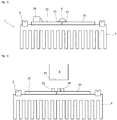
- the first and second printed circuit boards 22 and 32 are mounted together on a single metal heat sink 4, which is provided with mounting interfaces 41 and a seal 5 extending around the entire periphery of the heat sink. heat 4.
- the light module 1 can be mounted on a wall of a housing of a motor vehicle front lighting device provided with mounting means complementary to the mounting interfaces 41.
- the first and second printed circuit boards 22 and 32 are mounted on the metal heat sink 4 so as to be coplanar and such that a first edge 22a of the first board 22 extends substantially against a second edge 32a of the second card 32, with a set.
- the first light source 21 is mounted on the first printed circuit board 22 substantially at the level of the first edge 22a and that the second light source 31 is mounted on the second printed circuit board 32 substantially at the level of the second edge 32a, opposite the first light source 21.
- the first and second printed circuit boards 31 and 32 are electrically connected to each other by means of a plurality of metal ribbons 6, one end of each strip 6 being soldered to a connection terminal 23 of the first printed circuit board 21 and the other end of this strip 6 being soldered to a connection terminal 33 of the second printed circuit board 31.
- the light module 1 comprises a connector 24, mounted on the first printed circuit board 21 and arranged to receive an electrical power supply from a power source external to the light module 1, such as for example the battery of a motor vehicle.
- the first and second printed circuit boards 31 and 32 comprise a set of tracks and electronic components making it possible to transmit this electric power supply received on the connector 24 to one and / or the other of the light sources 21 and 22, in particular via the metal strip 6 with respect to the second light source 22.
- the light module 1 comprises a unit 7 for controlling and piloting said electric power supply.
- This unit 7 is arranged so as to convert said electric power supply into a power supply suitable for one or each of the light sources 21 and 22, as a function of instructions that it receives controlling the emission of one or more given light functions. and to switch this converted power supply to one and / or the other of the light sources 21 and 22, so that when this or these sources are powered by said converted power supply, it or they emit light making it possible to achieve one or one of the light functions associated with it or them and whose emission is required.
- the unit 7 is mounted on the first printed circuit board 31.
- the light module 1 comprises a light guide 8 having a coupling input face 81 arranged to couple the light emitted by the first and / or the second light source 21 and 22 in the light guide 8 so that this light is propagates in the light guide by total internal reflection on an internal wall of the light guide.
- the light guide 8 further comprises a decoupling face and a light outlet face (not shown), which are arranged so that light enters. propagating in the light guide 8 and meeting the decoupling face, is decoupled towards the output face through which it is emitted to the outside of the light module to form the or one of the light functions associated with the light source having emitted this light. It will thus be understood that the output face forms a common output face for performing the light functions associated with the first and second light sources 21 and 22.
- the invention cannot be limited to the embodiments specifically described in this document, and extends in particular to all equivalent means and to any technically operative combination of these means.
- Other types of optical element than that described could also be envisaged, and in particular an optical element of collimator type, of lens type or of reflector type.
Applications Claiming Priority (1)
| Application Number | Priority Date | Filing Date | Title |
|---|---|---|---|
| FR1915238A FR3105360B1 (fr) | 2019-12-20 | 2019-12-20 | Module lumineux d’un véhicule automobile comportant deux sources lumineuses |
Publications (2)
| Publication Number | Publication Date |
|---|---|
| EP3839331A1 true EP3839331A1 (de) | 2021-06-23 |
| EP3839331B1 EP3839331B1 (de) | 2023-04-19 |
Family
ID=69811325
Family Applications (1)
| Application Number | Title | Priority Date | Filing Date |
|---|---|---|---|
| EP20214784.9A Active EP3839331B1 (de) | 2019-12-20 | 2020-12-16 | Kraftfahrzeugleuchtmodul mit zwei lichtquellen |
Country Status (2)
| Country | Link |
|---|---|
| EP (1) | EP3839331B1 (de) |
| FR (1) | FR3105360B1 (de) |
Citations (7)
| Publication number | Priority date | Publication date | Assignee | Title |
|---|---|---|---|---|
| EP2161494A1 (de) | 2008-09-05 | 2010-03-10 | Hella KG Hueck & Co. | Beleuchtungseinrichtung für ein Kraftfahrzeug |
| WO2011078217A1 (ja) * | 2009-12-25 | 2011-06-30 | 株式会社小糸製作所 | 光源ユニット及び車輌用灯具 |
| US20140218954A1 (en) * | 2013-02-06 | 2014-08-07 | Samsung Electronics Co., Ltd. | Light-emitting device package module |
| DE102013108337A1 (de) * | 2013-08-02 | 2015-02-05 | Hella Kgaa Hueck & Co. | Beleuchtungsvorrichtung für Fahrzeuge |
| EP3190334A1 (de) * | 2016-01-11 | 2017-07-12 | Valeo Iluminacion | Lichtmodul für kraftfahrzeug mit zwei typen von lichtquellen |
| ITUA20164029A1 (it) * | 2016-06-01 | 2017-12-01 | Comelec S R L | Complesso di illuminazione per veicoli atto a illuminare aree distinte del corpo esterno del veicolo e in prossimità di esso, e corrispondente procedimento di illuminazione attuabile da detto complesso. |
| FR3056702A1 (fr) * | 2016-09-27 | 2018-03-30 | Valeo Vision | Module lumineux avec dispositif de pilotage integre |
-
2019
- 2019-12-20 FR FR1915238A patent/FR3105360B1/fr active Active
-
2020
- 2020-12-16 EP EP20214784.9A patent/EP3839331B1/de active Active
Patent Citations (7)
| Publication number | Priority date | Publication date | Assignee | Title |
|---|---|---|---|---|
| EP2161494A1 (de) | 2008-09-05 | 2010-03-10 | Hella KG Hueck & Co. | Beleuchtungseinrichtung für ein Kraftfahrzeug |
| WO2011078217A1 (ja) * | 2009-12-25 | 2011-06-30 | 株式会社小糸製作所 | 光源ユニット及び車輌用灯具 |
| US20140218954A1 (en) * | 2013-02-06 | 2014-08-07 | Samsung Electronics Co., Ltd. | Light-emitting device package module |
| DE102013108337A1 (de) * | 2013-08-02 | 2015-02-05 | Hella Kgaa Hueck & Co. | Beleuchtungsvorrichtung für Fahrzeuge |
| EP3190334A1 (de) * | 2016-01-11 | 2017-07-12 | Valeo Iluminacion | Lichtmodul für kraftfahrzeug mit zwei typen von lichtquellen |
| ITUA20164029A1 (it) * | 2016-06-01 | 2017-12-01 | Comelec S R L | Complesso di illuminazione per veicoli atto a illuminare aree distinte del corpo esterno del veicolo e in prossimità di esso, e corrispondente procedimento di illuminazione attuabile da detto complesso. |
| FR3056702A1 (fr) * | 2016-09-27 | 2018-03-30 | Valeo Vision | Module lumineux avec dispositif de pilotage integre |
Also Published As
| Publication number | Publication date |
|---|---|
| FR3105360B1 (fr) | 2022-07-22 |
| EP3839331B1 (de) | 2023-04-19 |
| FR3105360A1 (fr) | 2021-06-25 |
Similar Documents
| Publication | Publication Date | Title |
|---|---|---|
| EP3201514B1 (de) | Leuchtmodul mit mindestens einer komponente und einem verbinder auf einem wärmeableiter und beleuchtungsvorrichtung für kraftfahrzeug mit solch einem modul | |
| EP3190334B1 (de) | Lichtmodul für kraftfahrzeug mit zwei typen von lichtquellen | |
| FR3056702B1 (fr) | Module lumineux avec dispositif de pilotage integre | |
| FR3034169A1 (fr) | Module lumineux pour vehicule automobile comprenant deux guides de lumiere et un radiateur comprenant deux faces de montage | |
| EP3283329B1 (de) | Beleuchtungsmodul für den fahrgastraum eines kraftfahrzeugs | |
| EP0377352B1 (de) | Biegsames Leuchtband mit Leuchtdioden | |
| CN102947131B (zh) | 具有壳体包括支撑多个发光二极管的电路板的外部后视镜组件 | |
| WO2021098753A1 (zh) | 光导组件、车灯和车辆 | |
| EP2965972A1 (de) | Modul, das ein karosserieelement für ein kraftfahrzeug darstellt und zur äusseren ästhetik des fahrzeugs beträgt | |
| EP3839331B1 (de) | Kraftfahrzeugleuchtmodul mit zwei lichtquellen | |
| EP1445533A2 (de) | Kfz-Scheinwerfer mit Einabu-Zusatzmodul | |
| EP3604905A1 (de) | Leuchtmodul für ein kraftfahrzeug | |
| FR3032516A1 (fr) | Dispositif reflecteur d'un module lumineux avec blindage electromagnetique | |
| FR3084479A1 (fr) | Dispositif electronique et assemblage, incluant des guides d'ondes optiques | |
| WO2018050974A1 (fr) | Luminaire connectable à un réseau de télécommunication. | |
| FR3056679A1 (fr) | Dispositif avec modules lumineux maitre et esclave | |
| EP3383150B1 (de) | Stromversorgungsvorrichtung für mindestens eine led und mindestens ein elektronisches bauelement, mit einer ein insert enthaltenden stromversorgungssteuerschaltung | |
| EP3867565B1 (de) | Leuchtmodul mit zwei funktionen für eine optische beleuchtungs- und/oder signaleinheit eines fahrzeugs | |
| FR3087395A1 (fr) | Dispositif d’eclairage avant pour vehicule automobile | |
| FR2951048A1 (fr) | Module de commande electronique pour un dispositif d'eclairage et/ou signalisation de vehicule | |
| US20230366521A1 (en) | Vehicle lighting unit | |
| FR3048066A1 (fr) | Dispositif lumineux avec une source lumineuse a batonnets lumineux pour differentes fonctions photometriques | |
| FR3071037A1 (fr) | Module lumineux pour vehicule automobile | |
| EP3867563A1 (de) | Lichtmodul mit zwei fotometrischen funktionen mit unterschiedlichen lichtsignaturen | |
| CA2926681A1 (fr) | Feu de signalisation |
Legal Events
| Date | Code | Title | Description |
|---|---|---|---|
| PUAI | Public reference made under article 153(3) epc to a published international application that has entered the european phase |
Free format text: ORIGINAL CODE: 0009012 |
|
| STAA | Information on the status of an ep patent application or granted ep patent |
Free format text: STATUS: THE APPLICATION HAS BEEN PUBLISHED |
|
| AK | Designated contracting states |
Kind code of ref document: A1 Designated state(s): AL AT BE BG CH CY CZ DE DK EE ES FI FR GB GR HR HU IE IS IT LI LT LU LV MC MK MT NL NO PL PT RO RS SE SI SK SM TR |
|
| STAA | Information on the status of an ep patent application or granted ep patent |
Free format text: STATUS: REQUEST FOR EXAMINATION WAS MADE |
|
| 17P | Request for examination filed |
Effective date: 20211209 |
|
| RBV | Designated contracting states (corrected) |
Designated state(s): AL AT BE BG CH CY CZ DE DK EE ES FI FR GB GR HR HU IE IS IT LI LT LU LV MC MK MT NL NO PL PT RO RS SE SI SK SM TR |
|
| GRAP | Despatch of communication of intention to grant a patent |
Free format text: ORIGINAL CODE: EPIDOSNIGR1 |
|
| STAA | Information on the status of an ep patent application or granted ep patent |
Free format text: STATUS: GRANT OF PATENT IS INTENDED |
|
| INTG | Intention to grant announced |
Effective date: 20221024 |
|
| GRAS | Grant fee paid |
Free format text: ORIGINAL CODE: EPIDOSNIGR3 |
|
| GRAA | (expected) grant |
Free format text: ORIGINAL CODE: 0009210 |
|
| STAA | Information on the status of an ep patent application or granted ep patent |
Free format text: STATUS: THE PATENT HAS BEEN GRANTED |
|
| AK | Designated contracting states |
Kind code of ref document: B1 Designated state(s): AL AT BE BG CH CY CZ DE DK EE ES FI FR GB GR HR HU IE IS IT LI LT LU LV MC MK MT NL NO PL PT RO RS SE SI SK SM TR |
|
| REG | Reference to a national code |
Ref country code: GB Ref legal event code: FG4D Free format text: NOT ENGLISH |
|
| REG | Reference to a national code |
Ref country code: CH Ref legal event code: EP |
|
| REG | Reference to a national code |
Ref country code: DE Ref legal event code: R096 Ref document number: 602020009861 Country of ref document: DE |
|
| REG | Reference to a national code |
Ref country code: IE Ref legal event code: FG4D Free format text: LANGUAGE OF EP DOCUMENT: FRENCH |
|
| REG | Reference to a national code |
Ref country code: AT Ref legal event code: REF Ref document number: 1561444 Country of ref document: AT Kind code of ref document: T Effective date: 20230515 |
|
| P01 | Opt-out of the competence of the unified patent court (upc) registered |
Effective date: 20230528 |
|
| REG | Reference to a national code |
Ref country code: LT Ref legal event code: MG9D |
|
| REG | Reference to a national code |
Ref country code: NL Ref legal event code: MP Effective date: 20230419 |
|
| REG | Reference to a national code |
Ref country code: AT Ref legal event code: MK05 Ref document number: 1561444 Country of ref document: AT Kind code of ref document: T Effective date: 20230419 |
|
| PG25 | Lapsed in a contracting state [announced via postgrant information from national office to epo] |
Ref country code: NL Free format text: LAPSE BECAUSE OF FAILURE TO SUBMIT A TRANSLATION OF THE DESCRIPTION OR TO PAY THE FEE WITHIN THE PRESCRIBED TIME-LIMIT Effective date: 20230419 |
|
| PG25 | Lapsed in a contracting state [announced via postgrant information from national office to epo] |
Ref country code: SE Free format text: LAPSE BECAUSE OF FAILURE TO SUBMIT A TRANSLATION OF THE DESCRIPTION OR TO PAY THE FEE WITHIN THE PRESCRIBED TIME-LIMIT Effective date: 20230419 Ref country code: PT Free format text: LAPSE BECAUSE OF FAILURE TO SUBMIT A TRANSLATION OF THE DESCRIPTION OR TO PAY THE FEE WITHIN THE PRESCRIBED TIME-LIMIT Effective date: 20230821 Ref country code: NO Free format text: LAPSE BECAUSE OF FAILURE TO SUBMIT A TRANSLATION OF THE DESCRIPTION OR TO PAY THE FEE WITHIN THE PRESCRIBED TIME-LIMIT Effective date: 20230719 Ref country code: ES Free format text: LAPSE BECAUSE OF FAILURE TO SUBMIT A TRANSLATION OF THE DESCRIPTION OR TO PAY THE FEE WITHIN THE PRESCRIBED TIME-LIMIT Effective date: 20230419 Ref country code: AT Free format text: LAPSE BECAUSE OF FAILURE TO SUBMIT A TRANSLATION OF THE DESCRIPTION OR TO PAY THE FEE WITHIN THE PRESCRIBED TIME-LIMIT Effective date: 20230419 |
|
| PG25 | Lapsed in a contracting state [announced via postgrant information from national office to epo] |
Ref country code: RS Free format text: LAPSE BECAUSE OF FAILURE TO SUBMIT A TRANSLATION OF THE DESCRIPTION OR TO PAY THE FEE WITHIN THE PRESCRIBED TIME-LIMIT Effective date: 20230419 Ref country code: PL Free format text: LAPSE BECAUSE OF FAILURE TO SUBMIT A TRANSLATION OF THE DESCRIPTION OR TO PAY THE FEE WITHIN THE PRESCRIBED TIME-LIMIT Effective date: 20230419 Ref country code: LV Free format text: LAPSE BECAUSE OF FAILURE TO SUBMIT A TRANSLATION OF THE DESCRIPTION OR TO PAY THE FEE WITHIN THE PRESCRIBED TIME-LIMIT Effective date: 20230419 Ref country code: LT Free format text: LAPSE BECAUSE OF FAILURE TO SUBMIT A TRANSLATION OF THE DESCRIPTION OR TO PAY THE FEE WITHIN THE PRESCRIBED TIME-LIMIT Effective date: 20230419 Ref country code: IS Free format text: LAPSE BECAUSE OF FAILURE TO SUBMIT A TRANSLATION OF THE DESCRIPTION OR TO PAY THE FEE WITHIN THE PRESCRIBED TIME-LIMIT Effective date: 20230819 Ref country code: HR Free format text: LAPSE BECAUSE OF FAILURE TO SUBMIT A TRANSLATION OF THE DESCRIPTION OR TO PAY THE FEE WITHIN THE PRESCRIBED TIME-LIMIT Effective date: 20230419 Ref country code: GR Free format text: LAPSE BECAUSE OF FAILURE TO SUBMIT A TRANSLATION OF THE DESCRIPTION OR TO PAY THE FEE WITHIN THE PRESCRIBED TIME-LIMIT Effective date: 20230720 Ref country code: AL Free format text: LAPSE BECAUSE OF FAILURE TO SUBMIT A TRANSLATION OF THE DESCRIPTION OR TO PAY THE FEE WITHIN THE PRESCRIBED TIME-LIMIT Effective date: 20230419 |
|
| PG25 | Lapsed in a contracting state [announced via postgrant information from national office to epo] |
Ref country code: FI Free format text: LAPSE BECAUSE OF FAILURE TO SUBMIT A TRANSLATION OF THE DESCRIPTION OR TO PAY THE FEE WITHIN THE PRESCRIBED TIME-LIMIT Effective date: 20230419 |
|
| PG25 | Lapsed in a contracting state [announced via postgrant information from national office to epo] |
Ref country code: SK Free format text: LAPSE BECAUSE OF FAILURE TO SUBMIT A TRANSLATION OF THE DESCRIPTION OR TO PAY THE FEE WITHIN THE PRESCRIBED TIME-LIMIT Effective date: 20230419 |
|
| REG | Reference to a national code |
Ref country code: DE Ref legal event code: R097 Ref document number: 602020009861 Country of ref document: DE |
|
| PG25 | Lapsed in a contracting state [announced via postgrant information from national office to epo] |
Ref country code: SM Free format text: LAPSE BECAUSE OF FAILURE TO SUBMIT A TRANSLATION OF THE DESCRIPTION OR TO PAY THE FEE WITHIN THE PRESCRIBED TIME-LIMIT Effective date: 20230419 Ref country code: SK Free format text: LAPSE BECAUSE OF FAILURE TO SUBMIT A TRANSLATION OF THE DESCRIPTION OR TO PAY THE FEE WITHIN THE PRESCRIBED TIME-LIMIT Effective date: 20230419 Ref country code: RO Free format text: LAPSE BECAUSE OF FAILURE TO SUBMIT A TRANSLATION OF THE DESCRIPTION OR TO PAY THE FEE WITHIN THE PRESCRIBED TIME-LIMIT Effective date: 20230419 Ref country code: EE Free format text: LAPSE BECAUSE OF FAILURE TO SUBMIT A TRANSLATION OF THE DESCRIPTION OR TO PAY THE FEE WITHIN THE PRESCRIBED TIME-LIMIT Effective date: 20230419 Ref country code: DK Free format text: LAPSE BECAUSE OF FAILURE TO SUBMIT A TRANSLATION OF THE DESCRIPTION OR TO PAY THE FEE WITHIN THE PRESCRIBED TIME-LIMIT Effective date: 20230419 Ref country code: CZ Free format text: LAPSE BECAUSE OF FAILURE TO SUBMIT A TRANSLATION OF THE DESCRIPTION OR TO PAY THE FEE WITHIN THE PRESCRIBED TIME-LIMIT Effective date: 20230419 |
|
| PGFP | Annual fee paid to national office [announced via postgrant information from national office to epo] |
Ref country code: FR Payment date: 20231220 Year of fee payment: 4 Ref country code: DE Payment date: 20231208 Year of fee payment: 4 |
|
| PLBE | No opposition filed within time limit |
Free format text: ORIGINAL CODE: 0009261 |
|
| STAA | Information on the status of an ep patent application or granted ep patent |
Free format text: STATUS: NO OPPOSITION FILED WITHIN TIME LIMIT |
|
| 26N | No opposition filed |
Effective date: 20240122 |
|
| PG25 | Lapsed in a contracting state [announced via postgrant information from national office to epo] |
Ref country code: SI Free format text: LAPSE BECAUSE OF FAILURE TO SUBMIT A TRANSLATION OF THE DESCRIPTION OR TO PAY THE FEE WITHIN THE PRESCRIBED TIME-LIMIT Effective date: 20230419 |