EP3839331A1 - Light module for a motor vehicle comprising two light sources - Google Patents
Light module for a motor vehicle comprising two light sources Download PDFInfo
- Publication number
- EP3839331A1 EP3839331A1 EP20214784.9A EP20214784A EP3839331A1 EP 3839331 A1 EP3839331 A1 EP 3839331A1 EP 20214784 A EP20214784 A EP 20214784A EP 3839331 A1 EP3839331 A1 EP 3839331A1
- Authority
- EP
- European Patent Office
- Prior art keywords
- light
- printed circuit
- circuit board
- light source
- module
- Prior art date
- Legal status (The legal status is an assumption and is not a legal conclusion. Google has not performed a legal analysis and makes no representation as to the accuracy of the status listed.)
- Granted
Links
- 230000001105 regulatory effect Effects 0.000 claims description 14
- 239000004065 semiconductor Substances 0.000 claims description 8
- 230000003287 optical effect Effects 0.000 claims description 7
- 239000002184 metal Substances 0.000 description 11
- 230000001276 controlling effect Effects 0.000 description 3
- 230000008878 coupling Effects 0.000 description 2
- 238000010168 coupling process Methods 0.000 description 2
- 238000005859 coupling reaction Methods 0.000 description 2
- 230000011664 signaling Effects 0.000 description 2
- 229910000679 solder Inorganic materials 0.000 description 2
- 230000000295 complement effect Effects 0.000 description 1
- 230000001902 propagating effect Effects 0.000 description 1
- 239000000758 substrate Substances 0.000 description 1
Images

Classifications
-
- F—MECHANICAL ENGINEERING; LIGHTING; HEATING; WEAPONS; BLASTING
- F21—LIGHTING
- F21S—NON-PORTABLE LIGHTING DEVICES; SYSTEMS THEREOF; VEHICLE LIGHTING DEVICES SPECIALLY ADAPTED FOR VEHICLE EXTERIORS
- F21S45/00—Arrangements within vehicle lighting devices specially adapted for vehicle exteriors, for purposes other than emission or distribution of light
- F21S45/40—Cooling of lighting devices
- F21S45/47—Passive cooling, e.g. using fins, thermal conductive elements or openings
-
- B—PERFORMING OPERATIONS; TRANSPORTING
- B60—VEHICLES IN GENERAL
- B60Q—ARRANGEMENT OF SIGNALLING OR LIGHTING DEVICES, THE MOUNTING OR SUPPORTING THEREOF OR CIRCUITS THEREFOR, FOR VEHICLES IN GENERAL
- B60Q1/00—Arrangement of optical signalling or lighting devices, the mounting or supporting thereof or circuits therefor
- B60Q1/26—Arrangement of optical signalling or lighting devices, the mounting or supporting thereof or circuits therefor the devices being primarily intended to indicate the vehicle, or parts thereof, or to give signals, to other traffic
- B60Q1/2607—Arrangement of optical signalling or lighting devices, the mounting or supporting thereof or circuits therefor the devices being primarily intended to indicate the vehicle, or parts thereof, or to give signals, to other traffic comprising at least two indicating lamps
-
- F—MECHANICAL ENGINEERING; LIGHTING; HEATING; WEAPONS; BLASTING
- F21—LIGHTING
- F21S—NON-PORTABLE LIGHTING DEVICES; SYSTEMS THEREOF; VEHICLE LIGHTING DEVICES SPECIALLY ADAPTED FOR VEHICLE EXTERIORS
- F21S43/00—Signalling devices specially adapted for vehicle exteriors, e.g. brake lamps, direction indicator lights or reversing lights
- F21S43/10—Signalling devices specially adapted for vehicle exteriors, e.g. brake lamps, direction indicator lights or reversing lights characterised by the light source
- F21S43/13—Signalling devices specially adapted for vehicle exteriors, e.g. brake lamps, direction indicator lights or reversing lights characterised by the light source characterised by the type of light source
- F21S43/14—Light emitting diodes [LED]
-
- F—MECHANICAL ENGINEERING; LIGHTING; HEATING; WEAPONS; BLASTING
- F21—LIGHTING
- F21S—NON-PORTABLE LIGHTING DEVICES; SYSTEMS THEREOF; VEHICLE LIGHTING DEVICES SPECIALLY ADAPTED FOR VEHICLE EXTERIORS
- F21S43/00—Signalling devices specially adapted for vehicle exteriors, e.g. brake lamps, direction indicator lights or reversing lights
- F21S43/10—Signalling devices specially adapted for vehicle exteriors, e.g. brake lamps, direction indicator lights or reversing lights characterised by the light source
- F21S43/19—Attachment of light sources or lamp holders
- F21S43/195—Details of lamp holders, terminals or connectors
-
- F—MECHANICAL ENGINEERING; LIGHTING; HEATING; WEAPONS; BLASTING
- F21—LIGHTING
- F21S—NON-PORTABLE LIGHTING DEVICES; SYSTEMS THEREOF; VEHICLE LIGHTING DEVICES SPECIALLY ADAPTED FOR VEHICLE EXTERIORS
- F21S43/00—Signalling devices specially adapted for vehicle exteriors, e.g. brake lamps, direction indicator lights or reversing lights
- F21S43/20—Signalling devices specially adapted for vehicle exteriors, e.g. brake lamps, direction indicator lights or reversing lights characterised by refractors, transparent cover plates, light guides or filters
-
- B—PERFORMING OPERATIONS; TRANSPORTING
- B60—VEHICLES IN GENERAL
- B60Q—ARRANGEMENT OF SIGNALLING OR LIGHTING DEVICES, THE MOUNTING OR SUPPORTING THEREOF OR CIRCUITS THEREFOR, FOR VEHICLES IN GENERAL
- B60Q2400/00—Special features or arrangements of exterior signal lamps for vehicles
- B60Q2400/20—Multi-color single source or LED matrix, e.g. yellow blinker and red brake lamp generated by single lamp
-
- B—PERFORMING OPERATIONS; TRANSPORTING
- B60—VEHICLES IN GENERAL
- B60Q—ARRANGEMENT OF SIGNALLING OR LIGHTING DEVICES, THE MOUNTING OR SUPPORTING THEREOF OR CIRCUITS THEREFOR, FOR VEHICLES IN GENERAL
- B60Q2400/00—Special features or arrangements of exterior signal lamps for vehicles
- B60Q2400/30—Daytime running lights [DRL], e.g. circuits or arrangements therefor
-
- F—MECHANICAL ENGINEERING; LIGHTING; HEATING; WEAPONS; BLASTING
- F21—LIGHTING
- F21W—INDEXING SCHEME ASSOCIATED WITH SUBCLASSES F21K, F21L, F21S and F21V, RELATING TO USES OR APPLICATIONS OF LIGHTING DEVICES OR SYSTEMS
- F21W2103/00—Exterior vehicle lighting devices for signalling purposes
- F21W2103/20—Direction indicator lights
-
- F—MECHANICAL ENGINEERING; LIGHTING; HEATING; WEAPONS; BLASTING
- F21—LIGHTING
- F21W—INDEXING SCHEME ASSOCIATED WITH SUBCLASSES F21K, F21L, F21S and F21V, RELATING TO USES OR APPLICATIONS OF LIGHTING DEVICES OR SYSTEMS
- F21W2103/00—Exterior vehicle lighting devices for signalling purposes
- F21W2103/55—Daytime running lights [DRL]
Landscapes
- Engineering & Computer Science (AREA)
- General Engineering & Computer Science (AREA)
- Physics & Mathematics (AREA)
- Microelectronics & Electronic Packaging (AREA)
- Optics & Photonics (AREA)
- Mechanical Engineering (AREA)
- Non-Portable Lighting Devices Or Systems Thereof (AREA)
- Combinations Of Printed Boards (AREA)
Abstract
Module lumineux (1) d'un véhicule automobile, comportant une première source lumineuse (21) associée à au moins une première fonction lumineuse prédéterminée et une deuxième source lumineuse (31) associée à au moins une deuxième fonction lumineuse prédéterminée, dans lequel la première source lumineuse est montée sur une première carte de circuit imprimé (22) et la deuxième source lumineuse est montée sur une deuxième carte de circuit imprimé (32) distincte de la première carte de circuit imprimé, caractérisée en ce qu'il comporte un connecteur (24) agencé pour recevoir une alimentation électrique destinée à l'alimentation électrique des première et/ou deuxième sources lumineuses pour la réalisation des première et/ou deuxième fonctions lumineuses prédéterminées, le connecteur étant monté sur la première carte de circuit imprimé et la première carte de circuit imprimé étant reliée électriquement à la deuxième carte de circuit imprimé par un élément conducteur (6) soudé à chacune des première et deuxième cartes de circuit imprimé.Light module (1) of a motor vehicle, comprising a first light source (21) associated with at least one first predetermined light function and a second light source (31) associated with at least one second predetermined light function, in which the first light source is mounted on a first printed circuit board (22) and the second light source is mounted on a second printed circuit board (32) separate from the first printed circuit board, characterized in that it has a connector ( 24) arranged to receive a power supply intended for the power supply of the first and / or second light sources for the realization of the first and / or second predetermined light functions, the connector being mounted on the first printed circuit board and the first board circuit board being electrically connected to the second printed circuit board by a conductive element (6) soldered to each of the pr first and second printed circuit boards.
Description
L'invention concerne le domaine de l'éclairage et de la signalisation lumineuse des véhicules automobiles. Plus précisément, l'invention concerne un module lumineux de véhicule automobile comportant au moins deux sources lumineuses.The invention relates to the field of lighting and light signaling of motor vehicles. More specifically, the invention relates to a motor vehicle light module comprising at least two light sources.
Dans le domaine de l'éclairage et de la signalisation des véhicules automobiles, il existe des fonctions lumineuses dites mutuellement incorporées, qui sont émises via une même surface de sortie d'un module lumineux. C'est par exemple le cas des fonctions d'indicateur de direction et de feu diurne, qui peuvent être mutuellement incorporées.In the field of lighting and signaling of motor vehicles, there are so-called mutually incorporated light functions, which are emitted via the same output surface of a light module. This is the case, for example, of the direction indicator and daytime running light functions, which can be mutually incorporated.
Le document
En alternative, il est possible de monter chaque source lumineuse associée à l'une des fonctions sur une carte de circuit imprimé qui lui est propre. Toutefois, cette solution impose de multiplier les faisceaux de connexion pour la fourniture d'une alimentation électrique à chacune des sources lumineuses et les connecteurs sur les cartes de circuit imprimé pour recevoir ces alimentations. Cette solution accroit donc le coût du module lumineux et complexifie son assemblage.As an alternative, it is possible to mount each light source associated with one of the functions on a printed circuit board which is specific to it. However, this solution makes it necessary to multiply the connection harnesses for the supply of an electric power supply to each of the light sources and the connectors on the printed circuit boards to receive these power supplies. This solution therefore increases the cost of the light module and makes its assembly more complex.
Il existe ainsi un besoin d'une solution alternative aux solutions connues, notamment illustrée par le document cité, et qui soit simple et peu couteuse. L'invention vise à réponse à ce besoin.There is thus a need for an alternative solution to known solutions, illustrated in particular by the cited document, and which is simple and inexpensive. The invention aims to meet this need.
A ces fins, l'invention concerne un module lumineux d'un véhicule automobile, comportant une première source lumineuse associée à au moins une première fonction lumineuse prédéterminée et une deuxième source lumineuse associée à au moins une deuxième fonction lumineuse prédéterminée, dans lequel la première source lumineuse est montée sur une première carte de circuit imprimé et la deuxième source lumineuse est montée sur une deuxième carte de circuit imprimé distincte de la première carte de circuit imprimé, caractérisée en ce qu'il comporte un connecteur agencé pour recevoir une alimentation électrique destinée à l'alimentation électrique des première et/ou deuxième sources lumineuses pour la réalisation des première et/ou deuxième fonctions lumineuses prédéterminées, le connecteur étant monté sur la première carte de circuit imprimé et la première carte de circuit imprimé étant reliée électriquement à la deuxième carte de circuit imprimé par un élément conducteur soudé à chacune des première et deuxième cartes de circuit imprimé.For these purposes, the invention relates to a light module of a motor vehicle, comprising a first light source associated with at least one first predetermined light function and a second light source associated with at least one second predetermined light function, in which the first light source is mounted on a first printed circuit board and the second light source is mounted on a second printed circuit board separate from the first printed circuit board, characterized in that it comprises a connector arranged to receive a power supply intended for the power supply of the first and / or second light sources for the realization of the first and / or second predetermined light functions, the connector being mounted on the first card of printed circuit board and the first printed circuit board being electrically connected to the second printed circuit board by a conductive member soldered to each of the first and second printed circuit boards.
L'invention propose ainsi une alternative aux solutions connues, en ce que la première source lumineuse et la deuxième source lumineuse sont montées sur des cartes de circuit imprimé distinctes. En outre, selon l'invention, un seul connecteur est employé pour recevoir une alimentation électrique pour les deux sources lumineuses, cette alimentation électrique étant transmise à la deuxième source lumineuse depuis la première carte de circuit imprimé via l'élément conducteur.The invention thus proposes an alternative to known solutions, in that the first light source and the second light source are mounted on separate printed circuit boards. Furthermore, according to the invention, a single connector is employed to receive a power supply for the two light sources, this power supply being transmitted to the second light source from the first printed circuit board via the conductive element.
On entend par « source lumineuse associé à une fonction lumineuse prédéterminée » le fait que la fonction lumineuse prédéterminée est réalisée à partir de la lumière émise par la source lumineuse lorsqu'elle est alimentée par une alimentation électrique, seule ou en combinaison avec de la lumière émise par une autre source lumineuse, directement ou après déviation par un dispositif optique.The term “light source associated with a predetermined light function” is understood to mean the fact that the predetermined light function is produced from the light emitted by the light source when it is supplied by an electrical supply, alone or in combination with light. emitted by another light source, directly or after deflection by an optical device.
Avantageusement, la première carte de circuit imprimé et la deuxième carte de circuit imprimé sont agencées de sorte que ladite alimentation électrique reçue par ledit connecteur puisse être transmise à la deuxième source lumineuse, via l'élément conducteur. Le cas échéant, la deuxième carte de circuit imprimé est dépourvue de connecteur pour la réception d'une alimentation électrique. Si on le souhaite, le module lumineux peut comporter un circuit de pilotage pour contrôler l'alimentation électrique fournie aux première et deuxième sources lumineuses à partir de l'alimentation électrique reçue par le connecteur, le circuit de pilotage étant par exemple monté sur la première carte de circuit imprimé. Eventuellement, la première carte de circuit imprimé peut être une carte de circuit imprimé de type FR4 (de l'anglais Flame Resistant 4) et la deuxième carte de circuit imprimé peut être une carte de circuit imprimé de type SMI ou à Substrat Métallique Isolé.Advantageously, the first printed circuit board and the second printed circuit board are arranged so that said electric power supply received by said connector can be transmitted to the second light source, via the conductive element. If necessary, the second printed circuit board is devoid of a connector for receiving a power supply. If desired, the light module can include a control circuit for controlling the power supply supplied to the first and second light sources from the power supply received by the connector, the driver circuit being for example mounted on the first printed circuit board. Optionally, the first printed circuit board may be a printed circuit board of FR4 type (standing for Flame Resistant 4) and the second printed circuit board may be a printed circuit board of the SMI type or with an Insulated Metal Substrate.
Avantageusement, les première et deuxième cartes de circuit imprimé sont montées sur un support commun. Par exemple, le support commun peut être un dissipateur de chaleur métallique ou en variante un support plastique.Advantageously, the first and second printed circuit boards are mounted on a common support. For example, the common support can be a metal heat sink or alternatively a plastic support.
Avantageusement, les première et deuxième cartes de circuit imprimé sont agencées de sorte qu'un premier bord de la première carte de circuit imprimé s'étende sensiblement contre un deuxième bord de la deuxième carte de circuit imprimé. Le cas échéant, le premier bord peut être en contact avec le deuxième bord ou en variante distant du deuxième bord. De préférence, les première et deuxième cartes de circuit imprimé sont coplanaires.Advantageously, the first and second printed circuit boards are arranged so that a first edge of the first printed circuit board extends substantially against a second edge of the second printed circuit board. Where appropriate, the first edge may be in contact with the second edge or alternatively remote from the second edge. Preferably, the first and second printed circuit boards are coplanar.
Avantageusement, la première source lumineuse est montée sur la première carte de circuit imprimé sensiblement au niveau du premier bord et dans lequel la deuxième source lumineuse est montée sur la deuxième carte de circuit imprimé sensiblement au niveau du deuxième bord et au niveau de la première source lumineuse.Advantageously, the first light source is mounted on the first printed circuit board substantially at the level of the first edge and in which the second light source is mounted on the second printed circuit board substantially at the level of the second edge and at the level of the first source bright.
Le cas échéant, le module lumineux peut comporter un élément optique présentant une face d'entrée de lumière commune agencée en vis-à-vis des première et deuxième sources lumineuses pour recevoir de la lumière émise par ces sources et une face de sortie de lumière commune pour la réalisation desdites première et deuxième fonctions lumineuses prédéterminées à partir de la lumière émise par les première et deuxième sources lumineuses. Par exemple, l'élément optique pourra être un guide de lumière présentant une face d'entrée de couplage, une face de découplage et une face de sortie, la face d'entrée étant agencée pour coupler la lumière émise par la première et/ou la deuxième source lumineuse dans le guide de lumière de sorte que cette lumière se propage dans le guide de lumière par réflexion interne totale sur une paroi interne du guide de lumière jusqu'à rencontrer la face de découplage, laquelle est agencée pour découpler cette lumière vers la face de sortie au travers de laquelle elle est émise vers l'extérieur du module lumineux. En variante, l'élément optique pourra présenter deux faces d'entrée de lumière chacune dédiée à l'une des première et deuxième sources lumineuses et une face de sortie de lumière commune.Where appropriate, the light module may include an optical element having a common light input face arranged opposite the first and second light sources to receive light emitted by these sources and a light output face. common for carrying out said first and second predetermined light functions from the light emitted by the first and second light sources. For example, the optical element could be a light guide having a coupling input face, a decoupling face and an output face, the input face being arranged to couple the light emitted by the first and / or the second light source in the light guide so that this light propagates in the light guide by total internal reflection on an internal wall of the light guide until it meets the decoupling face, which is arranged to decouple this light towards the exit face through which it is emitted to the outside of the light module. As a variant, the optical element may have two light input faces each dedicated to one of the first and second light sources and a common light output face.
Avantageusement, l'élément conducteur est un ruban métallique. Le cas échéant, la première carte de circuit imprimé pourra comporter une borne de connexion à laquelle est soudée une extrémité dudit ruban métallique et la deuxième carte de circuit imprimé pourra comporter une borne de connexion à laquelle est soudée l'autre extrémité dudit ruban métallique. En variante, l'élément conducteur pourra être un fil métallique ou encore un pont de soudure. Si on le souhaite, la première carte de circuit imprimé peut être reliée électriquement à la deuxième carte de circuit imprimé par une pluralité d'éléments conducteurs chacun soudé de part et d'autre aux première et deuxième cartes de circuit imprimé.Advantageously, the conductive element is a metal strip. Where appropriate, the first printed circuit board may include a connection terminal to which one end of said metal tape is soldered and the second printed circuit board may include a connection terminal to which the other end of said metal tape is welded. As a variant, the conductive element could be a metal wire or even a solder bridge. If desired, the first printed circuit board can be electrically connected to the second printed circuit board by a plurality of conductive elements each soldered on either side to the first and second printed circuit boards.
Dans un exemple de réalisation de l'invention, la première source lumineuse comporte au moins une puce à semi-conducteur émettrice de lumière de couleur ambre, la deuxième fonction lumineuse étant une fonction de type indicateur de direction réglementaire. Si on le souhaite, la première source lumineuse comporte une pluralité de puces à semi-conducteur émettrices de lumière de couleur ambre, destinées à participer ensemble à la réalisation de ladite fonction de type indicateur de direction réglementaire. On entend par indicateur de direction réglementaire par exemple une fonction lumineuse de type indicateur de direction respectant les prescriptions réglementaires d'un pays ou d'une région donnée, et par exemple la réglementation européenne ECE R48.In an exemplary embodiment of the invention, the first light source comprises at least one semiconductor chip emitting amber-colored light, the second light function being a function of the regulatory direction indicator type. If desired, the first light source comprises a plurality of semiconductor chips emitting amber light, intended to participate together in the performance of said regulatory direction indicator type function. By regulatory direction indicator is meant, for example, a light function of the direction indicator type complying with the regulatory requirements of a given country or region, and for example European regulation ECE R48.
Le cas échéant, la deuxième source lumineuse peut comporter au moins une puce à semi-conducteur émettrice de lumière de couleur blanche, la première fonction lumineuse étant une fonction de type feu diurne réglementaire. Si on le souhaite, la deuxième source lumineuse comporte une pluralité de puces à semi-conducteur émettrices de lumière de couleur blanche, destinées à participer ensemble à la réalisation de ladite fonction de type feu diurne réglementaire. On entend par feu de jour réglementaire par exemple une fonction lumineuse de type feu diurne respectant les prescriptions réglementaires d'un pays ou d'une région donnée, et par exemple la réglementation européenne ECE 87.Where appropriate, the second light source may include at least one semiconductor chip emitting white light, the first light function being a function of the regulatory daytime running light type. If desired, the second light source comprises a plurality of semiconductor chips emitting white light, intended to participate together in performing said function of the regulatory daytime running light type. By regulatory daytime running light is meant, for example, a light function of the daytime running light type complying with the regulatory requirements of a given country or region, and for example European regulation ECE 87.
Avantageusement, le module lumineux peut comporter une unité de contrôle agencée pour contrôler sélectivement l'émission de lumière par la première source lumineuse ou par la deuxième source lumineuse. Si on le souhaite, ladite unité de contrôle peut être montée sur la première carte de circuit imprimé. De préférence, l'unité de contrôle peut être agencée pour contrôler l'alimentation électrique fournie à l'une ou l'autre des première et deuxième sources lumineuses de sorte que cette source lumineuse émette une lumière d'intensité lumineuse réduite pour participer à la réalisation d'une troisième fonction lumineuse prédéterminée, par exemple un feu de position réglementaire.Advantageously, the light module can include a control unit arranged to selectively control the emission of light by the first light source or by the second light source. If desired, said control unit can be mounted on the first printed circuit board. Preferably, the control unit can be arranged to control the power supply supplied to one or other of the first and second light sources so that this light source emits light of reduced light intensity to participate in the light source. realization of a third predetermined light function, for example a regulatory position light.
L'invention a également pour objet un dispositif d'éclairage avant d'un véhicule automobile, caractérisé en ce qu'il comporte un module lumineux selon l'invention.The subject of the invention is also a front lighting device for a motor vehicle, characterized in that it comprises a light module according to the invention.
La présente invention est maintenant décrite à l'aide d'exemples uniquement illustratifs et nullement limitatifs de la portée de l'invention, et à partir des illustrations jointes, dans lesquelles :
- [
Fig. 1 ] représente, schématique et partiellement, une vue de dessus d'un module lumineux selon un mode de réalisation de l'invention ; - [
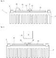
Fig. 2 ] représente une coupe par un premier plan du module lumineux de la [Fig. 1 ] ; et - [
Fig. 3 ] représente une coupe par un deuxième plan du module lumineux de la [Fig. 1 ].
- [
Fig. 1 ] shows, schematically and partially, a top view of a light module according to one embodiment of the invention; - [
Fig. 2 ] represents a section through a foreground of the light module of the [Fig. 1 ]; and - [
Fig. 3 ] represents a section through a second plane of the light module of the [Fig. 1 ].
Dans la description qui suit, les éléments identiques, par structure ou par fonction, apparaissant sur différentes figures conservent, sauf précision contraire, les mêmes références.In the following description, elements which are identical, by structure or by function, appearing in different figures retain, unless otherwise specified, the same references.
On a représenté en [
Le module lumineux 1 comporte une première source lumineuse 21 comprenant une pluralité de puces à semi-conducteur émettrices de lumière de couleur ambre et une deuxième source lumineuse 31 comprenant une pluralité de puces à semi-conducteur émettrices de lumière de couleur blanche.The
La première source lumineuse 21 est destinée à participer à la réalisation d'une première fonction lumineuse de type indicateur de direction réglementaire, qui lui est associée. La deuxième source lumineuse 31 est destinée à participer à la réalisation d'une deuxième fonction lumineuse de type feu diurne réglementaire et à la réalisation d'une troisième fonction lumineuse de type feu de position réglementaire, qui lui sont associées.The
La première source lumineuse 21 est montée sur une première carte de circuit imprimé 22 de type FR4 et la deuxième source lumineuse 31 est montée sur une deuxième carte de circuit imprimé 32 de type SMI, distincte de la première carte 22.The
Les première et deuxième cartes de circuit imprimé 22 et 32 sont montées ensemble sur un même dissipateur de chaleur métallique 4, lequel est pourvu d'interfaces de montage 41 et d'un joint d'étanchéité 5 s'étendant sur tout le pourtour du dissipateur de chaleur 4. De la sorte, le module lumineux 1 peut être monté sur une paroi d'un boîtier d'un dispositif d'éclairage avant de véhicule automobile pourvue de moyens de montage complémentaires aux interfaces de montage 41.The first and second printed
Les première et deuxième cartes de circuit imprimé 22 et 32 sont montées sur le dissipateur de chaleur métallique 4 de façon à être coplanaires et de sorte qu'un premier bord 22a de la première carte 22 s'étende sensiblement contre un deuxième bord 32a de la deuxième carte 32, avec un jeu. On notera que la première source lumineuse 21 est montée sur la première carte de circuit imprimé 22 sensiblement au niveau du premier bord 22a et que la deuxième source lumineuse 31 est montée sur la deuxième carte de circuit imprimée 32 sensiblement au niveau du deuxième bord 32a, en vis-à-vis de la première source lumineuse 21.The first and second printed
Afin d'assurer l'alimentation électrique des première et deuxième sources lumineuses 21 et 22, les première et deuxième cartes de circuit imprimé 31 et 32 sont reliées électriquement l'une à l'autre au moyen d'une pluralité de rubans métalliques 6, une extrémité de chaque ruban 6 étant soudée à une borne de connexion 23 de la première carte de circuit imprimé 21 et l'autre extrémité de ce ruban 6 étant soudée à une borne de connexion 33 de la deuxième carte de circuit imprimé 31. Par ailleurs, le module lumineux 1 comporte un connecteur 24, monté sur la première carte de circuit imprimé 21 et agencé pour recevoir une alimentation électrique depuis une source d'alimentation externe au module lumineux 1, comme par exemple la batterie d'un véhicule automobile.In order to ensure the power supply of the first and
Les première et deuxième cartes de circuit imprimé 31 et 32 comportent un ensemble de pistes et de composants électroniques permettant de transmettre cette alimentation électrique reçue sur le connecteur 24 vers l'une et/ou l'autre des sources lumineuses 21 et 22, notamment via le ruban métallique 6 en ce qui concerne la deuxième source lumineuse 22.The first and second printed
Plus spécifiquement, le module lumineux 1 comporte une unité 7 de contrôle et de pilotage de ladite alimentation électrique. Cette unité 7 est agencée pour, en fonction d'instructions qu'elle reçoit commandant l'émission d'une ou plusieurs fonctions lumineuses données, convertir ladite alimentation électrique en une alimentation adaptée à l'une ou à chacune des sources lumineuses 21 et 22 et pour commuter cette alimentation électrique convertie vers l'une et/ou l'autre des sources lumineuses 21 et 22, de sorte que lorsque cette ou ces sources sont alimentées par ladite alimentation électrique convertie, elle ou elles émettent de la lumière permettant de réaliser la ou l'une des fonctions lumineuses qui lui ou leur sont associées et dont l'émission est requise.More specifically, the
Dans l'exemple décrit, l'unité 7 est montée sur la première carte de circuit imprimé 31.In the example described, the
Le module lumineux 1 comporte un guide de lumière 8 présentant une face d'entrée de couplage 81 agencée pour coupler la lumière émise par la première et/ou la deuxième source lumineuse 21 et 22 dans le guide de lumière 8 de sorte que cette lumière se propage dans le guide de lumière par réflexion interne totale sur une paroi interne du guide de lumière. Le guide de lumière 8 comporte en outre une face de découplage et une face de sortie de lumière (non représentées), lesquelles sont agencées de sorte que de la lumière se propageant dans le guide de lumière 8 et rencontrant la face de découplage, soit découplée vers la face de sortie au travers de laquelle elle est émise vers l'extérieur du module lumineux pour former la ou l'une des fonctions lumineuses associées à la source lumineuse ayant émis cette lumière. On comprend ainsi que la face de sortie forme une face de sortie commune pour la réalisation des fonctions lumineuses associées aux première et deuxième sources lumineuses 21 et 22.The
La description qui précède explique clairement comment l'invention permet d'atteindre les objectifs qu'elle s'est fixée, et notamment en proposant un module lumineux comprenant deux sources lumineuses, chacune montée sur une carte de circuit imprimé qui lui est propre, et dans lequel seule l'une des cartes de circuit imprimé comporte un connecteur pour recevoir une alimentation électrique et dans lequel les deux cartes de circuit imprimé sont reliées électriquement par un élément conducteur pour transmettre cette alimentation électrique depuis l'une des cartes vers l'autre. On comprend ainsi que l'utilisation de deux cartes de circuit imprimé permet d'offrir une alternative aux solutions antérieures connues qui proposent de monter les deux sources lumineuses sur une même carte, et que l'utilisation d'un connecteur sur une seule des cartes de circuit imprimé permet de réduire le coût et de simplifier l'assemblage du module lumineux.The foregoing description clearly explains how the invention makes it possible to achieve the objectives that it has set itself, and in particular by proposing a light module comprising two light sources, each mounted on a printed circuit board which is specific to it, and in which only one of the printed circuit boards has a connector for receiving a power supply and in which the two printed circuit boards are electrically connected by a conductive element to transmit this power supply from one of the boards to the other . It is thus understood that the use of two printed circuit boards makes it possible to offer an alternative to the prior known solutions which propose mounting the two light sources on the same board, and that the use of a connector on only one of the boards printed circuit board reduces the cost and simplifies the assembly of the light module.
En tout état de cause, l'invention ne saurait se limiter aux modes de réalisation spécifiquement décrits dans ce document, et s'étend en particulier à tous moyens équivalents et à toute combinaison techniquement opérante de ces moyens. En particulier, on pourra prévoir d'autres types d'éléments conducteurs que celui décrit, et notamment des éléments conducteurs de type fil métallique ou de type pont de soudure. On pourra également envisager d'autres types d'élément optique que celui décrit, et notamment un élément optique de type collimateur, de type lentille ou encore de type réflecteur.In any event, the invention cannot be limited to the embodiments specifically described in this document, and extends in particular to all equivalent means and to any technically operative combination of these means. In particular, it is possible to provide other types of conductive elements than that described, and in particular conductive elements of metal wire type or of solder bridge type. Other types of optical element than that described could also be envisaged, and in particular an optical element of collimator type, of lens type or of reflector type.
Claims (10)
Applications Claiming Priority (1)
| Application Number | Priority Date | Filing Date | Title |
|---|---|---|---|
| FR1915238A FR3105360B1 (en) | 2019-12-20 | 2019-12-20 | Light module of a motor vehicle comprising two light sources |
Publications (2)
| Publication Number | Publication Date |
|---|---|
| EP3839331A1 true EP3839331A1 (en) | 2021-06-23 |
| EP3839331B1 EP3839331B1 (en) | 2023-04-19 |
Family
ID=69811325
Family Applications (1)
| Application Number | Title | Priority Date | Filing Date |
|---|---|---|---|
| EP20214784.9A Active EP3839331B1 (en) | 2019-12-20 | 2020-12-16 | Light module for a motor vehicle comprising two light sources |
Country Status (2)
| Country | Link |
|---|---|
| EP (1) | EP3839331B1 (en) |
| FR (1) | FR3105360B1 (en) |
Citations (7)
| Publication number | Priority date | Publication date | Assignee | Title |
|---|---|---|---|---|
| EP2161494A1 (en) | 2008-09-05 | 2010-03-10 | Hella KG Hueck & Co. | Lighting device for a motor vehicle |
| WO2011078217A1 (en) * | 2009-12-25 | 2011-06-30 | 株式会社小糸製作所 | Light source unit and vehicle lighting fixture |
| US20140218954A1 (en) * | 2013-02-06 | 2014-08-07 | Samsung Electronics Co., Ltd. | Light-emitting device package module |
| DE102013108337A1 (en) * | 2013-08-02 | 2015-02-05 | Hella Kgaa Hueck & Co. | Lighting device for vehicles |
| EP3190334A1 (en) * | 2016-01-11 | 2017-07-12 | Valeo Iluminacion | Lighting module for vehicle comprising two kinds of light sources |
| ITUA20164029A1 (en) * | 2016-06-01 | 2017-12-01 | Comelec S R L | Lighting assembly for vehicles designed to illuminate distinct areas of the external body of the vehicle and in the vicinity thereof, and corresponding lighting method that can be implemented by said complex. |
| FR3056702A1 (en) * | 2016-09-27 | 2018-03-30 | Valeo Vision | LUMINOUS MODULE WITH INTEGRATED DRIVER |
-
2019
- 2019-12-20 FR FR1915238A patent/FR3105360B1/en active Active
-
2020
- 2020-12-16 EP EP20214784.9A patent/EP3839331B1/en active Active
Patent Citations (7)
| Publication number | Priority date | Publication date | Assignee | Title |
|---|---|---|---|---|
| EP2161494A1 (en) | 2008-09-05 | 2010-03-10 | Hella KG Hueck & Co. | Lighting device for a motor vehicle |
| WO2011078217A1 (en) * | 2009-12-25 | 2011-06-30 | 株式会社小糸製作所 | Light source unit and vehicle lighting fixture |
| US20140218954A1 (en) * | 2013-02-06 | 2014-08-07 | Samsung Electronics Co., Ltd. | Light-emitting device package module |
| DE102013108337A1 (en) * | 2013-08-02 | 2015-02-05 | Hella Kgaa Hueck & Co. | Lighting device for vehicles |
| EP3190334A1 (en) * | 2016-01-11 | 2017-07-12 | Valeo Iluminacion | Lighting module for vehicle comprising two kinds of light sources |
| ITUA20164029A1 (en) * | 2016-06-01 | 2017-12-01 | Comelec S R L | Lighting assembly for vehicles designed to illuminate distinct areas of the external body of the vehicle and in the vicinity thereof, and corresponding lighting method that can be implemented by said complex. |
| FR3056702A1 (en) * | 2016-09-27 | 2018-03-30 | Valeo Vision | LUMINOUS MODULE WITH INTEGRATED DRIVER |
Also Published As
| Publication number | Publication date |
|---|---|
| FR3105360A1 (en) | 2021-06-25 |
| FR3105360B1 (en) | 2022-07-22 |
| EP3839331B1 (en) | 2023-04-19 |
Similar Documents
| Publication | Publication Date | Title |
|---|---|---|
| EP3201514B1 (en) | Luminous module comprising at least one component and a connector which are disposed on a heat dissipater, and lighting device for automotive vehicle comprising such a module | |
| EP3190334B1 (en) | Lighting module for vehicle comprising two kinds of light sources | |
| FR3056702B1 (en) | LUMINOUS MODULE WITH INTEGRATED DRIVER | |
| EP3283329B1 (en) | Lighting module for the passenger compartment of a motor vehicle | |
| EP0377352B1 (en) | Flexible lighting tape with electroluminescent diodes | |
| FR3034169A1 (en) | LUMINOUS MODULE FOR A MOTOR VEHICLE COMPRISING TWO LIGHT GUIDES AND A RADIATOR COMPRISING TWO ASSEMBLY FACES | |
| CN102947131B (en) | External rear-view mirror assembly having housing comprising circuit board supporting a plurality of light emitting diodes | |
| WO2021098753A1 (en) | Light guide assembly, vehicle light and vehicle | |
| EP3839331B1 (en) | Light module for a motor vehicle comprising two light sources | |
| EP2965972A1 (en) | Module forming a bodywork element for motor vehicles contributing to the exterior esthetics of the vehicle | |
| EP1445533A2 (en) | Motor vehicle headlamp with built-in complementary module | |
| FR3006775A1 (en) | SYSTEM FOR PROJECTING LUMINOUS INDICATIONS | |
| FR3032516A1 (en) | DEVICE REFLECTING A LIGHT MODULE WITH ELECTROMAGNETIC SHIELD | |
| FR3084479A1 (en) | ELECTRONIC DEVICE AND ASSEMBLY, INCLUDING OPTICAL WAVEGUIDES | |
| WO2018050974A1 (en) | Light fixture that can be connected to a telecommunication network | |
| EP3921680B1 (en) | Light emission system using a high-powered led | |
| FR3056679A1 (en) | DEVICE WITH MASTER AND SLAVE LIGHT MODULES | |
| EP3383150B1 (en) | Power supply device for at least one led and at least one electronic component, comprising a power supply control circuit provided with an insert | |
| EP3867565B1 (en) | Dual-function luminous module for an optical vehicle lighting and/or signalling unit | |
| US20230366521A1 (en) | Vehicle lighting unit | |
| FR2905162A1 (en) | Safety lighting block for ceiling or wall of building, has support with transparent body having one end extending perpendicular to plate and transmitting light at level of recess including microprisms for displaying light information | |
| FR3048066A1 (en) | LUMINOUS DEVICE WITH A LUMINOUS LIGHT SOURCE FOR DIFFERENT PHOTOMETRIC FUNCTIONS | |
| FR3071037A1 (en) | LUMINOUS MODULE FOR MOTOR VEHICLE | |
| CA2926681A1 (en) | Signalling light | |
| EP1111297A1 (en) | Support for a self powered emergency lighting unit and self powered unit comprising such a support |
Legal Events
| Date | Code | Title | Description |
|---|---|---|---|
| PUAI | Public reference made under article 153(3) epc to a published international application that has entered the european phase |
Free format text: ORIGINAL CODE: 0009012 |
|
| STAA | Information on the status of an ep patent application or granted ep patent |
Free format text: STATUS: THE APPLICATION HAS BEEN PUBLISHED |
|
| AK | Designated contracting states |
Kind code of ref document: A1 Designated state(s): AL AT BE BG CH CY CZ DE DK EE ES FI FR GB GR HR HU IE IS IT LI LT LU LV MC MK MT NL NO PL PT RO RS SE SI SK SM TR |
|
| STAA | Information on the status of an ep patent application or granted ep patent |
Free format text: STATUS: REQUEST FOR EXAMINATION WAS MADE |
|
| 17P | Request for examination filed |
Effective date: 20211209 |
|
| RBV | Designated contracting states (corrected) |
Designated state(s): AL AT BE BG CH CY CZ DE DK EE ES FI FR GB GR HR HU IE IS IT LI LT LU LV MC MK MT NL NO PL PT RO RS SE SI SK SM TR |
|
| GRAP | Despatch of communication of intention to grant a patent |
Free format text: ORIGINAL CODE: EPIDOSNIGR1 |
|
| STAA | Information on the status of an ep patent application or granted ep patent |
Free format text: STATUS: GRANT OF PATENT IS INTENDED |
|
| INTG | Intention to grant announced |
Effective date: 20221024 |
|
| GRAS | Grant fee paid |
Free format text: ORIGINAL CODE: EPIDOSNIGR3 |
|
| GRAA | (expected) grant |
Free format text: ORIGINAL CODE: 0009210 |
|
| STAA | Information on the status of an ep patent application or granted ep patent |
Free format text: STATUS: THE PATENT HAS BEEN GRANTED |
|
| AK | Designated contracting states |
Kind code of ref document: B1 Designated state(s): AL AT BE BG CH CY CZ DE DK EE ES FI FR GB GR HR HU IE IS IT LI LT LU LV MC MK MT NL NO PL PT RO RS SE SI SK SM TR |
|
| REG | Reference to a national code |
Ref country code: GB Ref legal event code: FG4D Free format text: NOT ENGLISH |
|
| REG | Reference to a national code |
Ref country code: CH Ref legal event code: EP |
|
| REG | Reference to a national code |
Ref country code: DE Ref legal event code: R096 Ref document number: 602020009861 Country of ref document: DE |
|
| REG | Reference to a national code |
Ref country code: IE Ref legal event code: FG4D Free format text: LANGUAGE OF EP DOCUMENT: FRENCH |
|
| REG | Reference to a national code |
Ref country code: AT Ref legal event code: REF Ref document number: 1561444 Country of ref document: AT Kind code of ref document: T Effective date: 20230515 |
|
| P01 | Opt-out of the competence of the unified patent court (upc) registered |
Effective date: 20230528 |
|
| REG | Reference to a national code |
Ref country code: LT Ref legal event code: MG9D |
|
| REG | Reference to a national code |
Ref country code: NL Ref legal event code: MP Effective date: 20230419 |
|
| REG | Reference to a national code |
Ref country code: AT Ref legal event code: MK05 Ref document number: 1561444 Country of ref document: AT Kind code of ref document: T Effective date: 20230419 |
|
| PG25 | Lapsed in a contracting state [announced via postgrant information from national office to epo] |
Ref country code: NL Free format text: LAPSE BECAUSE OF FAILURE TO SUBMIT A TRANSLATION OF THE DESCRIPTION OR TO PAY THE FEE WITHIN THE PRESCRIBED TIME-LIMIT Effective date: 20230419 |
|
| PG25 | Lapsed in a contracting state [announced via postgrant information from national office to epo] |
Ref country code: SE Free format text: LAPSE BECAUSE OF FAILURE TO SUBMIT A TRANSLATION OF THE DESCRIPTION OR TO PAY THE FEE WITHIN THE PRESCRIBED TIME-LIMIT Effective date: 20230419 Ref country code: PT Free format text: LAPSE BECAUSE OF FAILURE TO SUBMIT A TRANSLATION OF THE DESCRIPTION OR TO PAY THE FEE WITHIN THE PRESCRIBED TIME-LIMIT Effective date: 20230821 Ref country code: NO Free format text: LAPSE BECAUSE OF FAILURE TO SUBMIT A TRANSLATION OF THE DESCRIPTION OR TO PAY THE FEE WITHIN THE PRESCRIBED TIME-LIMIT Effective date: 20230719 Ref country code: ES Free format text: LAPSE BECAUSE OF FAILURE TO SUBMIT A TRANSLATION OF THE DESCRIPTION OR TO PAY THE FEE WITHIN THE PRESCRIBED TIME-LIMIT Effective date: 20230419 Ref country code: AT Free format text: LAPSE BECAUSE OF FAILURE TO SUBMIT A TRANSLATION OF THE DESCRIPTION OR TO PAY THE FEE WITHIN THE PRESCRIBED TIME-LIMIT Effective date: 20230419 |
|
| PG25 | Lapsed in a contracting state [announced via postgrant information from national office to epo] |
Ref country code: RS Free format text: LAPSE BECAUSE OF FAILURE TO SUBMIT A TRANSLATION OF THE DESCRIPTION OR TO PAY THE FEE WITHIN THE PRESCRIBED TIME-LIMIT Effective date: 20230419 Ref country code: PL Free format text: LAPSE BECAUSE OF FAILURE TO SUBMIT A TRANSLATION OF THE DESCRIPTION OR TO PAY THE FEE WITHIN THE PRESCRIBED TIME-LIMIT Effective date: 20230419 Ref country code: LV Free format text: LAPSE BECAUSE OF FAILURE TO SUBMIT A TRANSLATION OF THE DESCRIPTION OR TO PAY THE FEE WITHIN THE PRESCRIBED TIME-LIMIT Effective date: 20230419 Ref country code: LT Free format text: LAPSE BECAUSE OF FAILURE TO SUBMIT A TRANSLATION OF THE DESCRIPTION OR TO PAY THE FEE WITHIN THE PRESCRIBED TIME-LIMIT Effective date: 20230419 Ref country code: IS Free format text: LAPSE BECAUSE OF FAILURE TO SUBMIT A TRANSLATION OF THE DESCRIPTION OR TO PAY THE FEE WITHIN THE PRESCRIBED TIME-LIMIT Effective date: 20230819 Ref country code: HR Free format text: LAPSE BECAUSE OF FAILURE TO SUBMIT A TRANSLATION OF THE DESCRIPTION OR TO PAY THE FEE WITHIN THE PRESCRIBED TIME-LIMIT Effective date: 20230419 Ref country code: GR Free format text: LAPSE BECAUSE OF FAILURE TO SUBMIT A TRANSLATION OF THE DESCRIPTION OR TO PAY THE FEE WITHIN THE PRESCRIBED TIME-LIMIT Effective date: 20230720 Ref country code: AL Free format text: LAPSE BECAUSE OF FAILURE TO SUBMIT A TRANSLATION OF THE DESCRIPTION OR TO PAY THE FEE WITHIN THE PRESCRIBED TIME-LIMIT Effective date: 20230419 |
|
| PG25 | Lapsed in a contracting state [announced via postgrant information from national office to epo] |
Ref country code: FI Free format text: LAPSE BECAUSE OF FAILURE TO SUBMIT A TRANSLATION OF THE DESCRIPTION OR TO PAY THE FEE WITHIN THE PRESCRIBED TIME-LIMIT Effective date: 20230419 |
|
| PG25 | Lapsed in a contracting state [announced via postgrant information from national office to epo] |
Ref country code: SK Free format text: LAPSE BECAUSE OF FAILURE TO SUBMIT A TRANSLATION OF THE DESCRIPTION OR TO PAY THE FEE WITHIN THE PRESCRIBED TIME-LIMIT Effective date: 20230419 |
|
| REG | Reference to a national code |
Ref country code: DE Ref legal event code: R097 Ref document number: 602020009861 Country of ref document: DE |
|
| PG25 | Lapsed in a contracting state [announced via postgrant information from national office to epo] |
Ref country code: SM Free format text: LAPSE BECAUSE OF FAILURE TO SUBMIT A TRANSLATION OF THE DESCRIPTION OR TO PAY THE FEE WITHIN THE PRESCRIBED TIME-LIMIT Effective date: 20230419 Ref country code: SK Free format text: LAPSE BECAUSE OF FAILURE TO SUBMIT A TRANSLATION OF THE DESCRIPTION OR TO PAY THE FEE WITHIN THE PRESCRIBED TIME-LIMIT Effective date: 20230419 Ref country code: RO Free format text: LAPSE BECAUSE OF FAILURE TO SUBMIT A TRANSLATION OF THE DESCRIPTION OR TO PAY THE FEE WITHIN THE PRESCRIBED TIME-LIMIT Effective date: 20230419 Ref country code: EE Free format text: LAPSE BECAUSE OF FAILURE TO SUBMIT A TRANSLATION OF THE DESCRIPTION OR TO PAY THE FEE WITHIN THE PRESCRIBED TIME-LIMIT Effective date: 20230419 Ref country code: DK Free format text: LAPSE BECAUSE OF FAILURE TO SUBMIT A TRANSLATION OF THE DESCRIPTION OR TO PAY THE FEE WITHIN THE PRESCRIBED TIME-LIMIT Effective date: 20230419 Ref country code: CZ Free format text: LAPSE BECAUSE OF FAILURE TO SUBMIT A TRANSLATION OF THE DESCRIPTION OR TO PAY THE FEE WITHIN THE PRESCRIBED TIME-LIMIT Effective date: 20230419 |
|
| PGFP | Annual fee paid to national office [announced via postgrant information from national office to epo] |
Ref country code: FR Payment date: 20231220 Year of fee payment: 4 Ref country code: DE Payment date: 20231208 Year of fee payment: 4 |
|
| PLBE | No opposition filed within time limit |
Free format text: ORIGINAL CODE: 0009261 |
|
| STAA | Information on the status of an ep patent application or granted ep patent |
Free format text: STATUS: NO OPPOSITION FILED WITHIN TIME LIMIT |
|
| 26N | No opposition filed |
Effective date: 20240122 |