EP3838721A1 - Élément de panneau - Google Patents
Élément de panneau Download PDFInfo
- Publication number
- EP3838721A1 EP3838721A1 EP19859952.4A EP19859952A EP3838721A1 EP 3838721 A1 EP3838721 A1 EP 3838721A1 EP 19859952 A EP19859952 A EP 19859952A EP 3838721 A1 EP3838721 A1 EP 3838721A1
- Authority
- EP
- European Patent Office
- Prior art keywords
- recessed part
- recessed
- panel member
- part group
- parts
- Prior art date
- Legal status (The legal status is an assumption and is not a legal conclusion. Google has not performed a legal analysis and makes no representation as to the accuracy of the status listed.)
- Pending
Links
Images


Classifications
-
- B—PERFORMING OPERATIONS; TRANSPORTING
- B62—LAND VEHICLES FOR TRAVELLING OTHERWISE THAN ON RAILS
- B62D—MOTOR VEHICLES; TRAILERS
- B62D25/00—Superstructure or monocoque structure sub-units; Parts or details thereof not otherwise provided for
- B62D25/20—Floors or bottom sub-units
-
- B—PERFORMING OPERATIONS; TRANSPORTING
- B62—LAND VEHICLES FOR TRAVELLING OTHERWISE THAN ON RAILS
- B62D—MOTOR VEHICLES; TRAILERS
- B62D21/00—Understructures, i.e. chassis frame on which a vehicle body may be mounted
- B62D21/15—Understructures, i.e. chassis frame on which a vehicle body may be mounted having impact absorbing means, e.g. a frame designed to permanently or temporarily change shape or dimension upon impact with another body
Definitions
- the present invention relates to a panel member of an automobile.
- a vehicle body of an automobile is required to be improved in collision performance and reduced in weight.
- the collision performance is secured mainly by a member such as a side member, a side sill or the like constituting a frame of the vehicle body.
- a member such as a side member, a side sill or the like constituting a frame of the vehicle body.
- To further improve the collision performance there are methods of increasing the plate thickness of the material of the frame and providing a reinforcing member at the frame, but those methods are not preferable in terms of weight reduction.
- to improve the collision performance there is, for example, a conceivable method of increasing a resistance force against a collision in, for example, a panel member such as a floor panel connecting to the side sill.
- Patent Document 1 discloses a floor panel in which circular recessed parts are arranged in a honeycomb shape in a floor panel main body portion, and the recessed parts are coupled by ribs.
- Patent Document 2 discloses a floor panel in which circular rigidity adjustment parts are provided at a front part in the vehicle length direction.
- Patent Document 3 discloses a composite module-type energy absorbing assembly effectively absorbing energy in various apparatuses, and discloses a constitution in which, for example, a plurality of circular recessed parts are arranged in parallel (see FIG. 3 , FIG. 11 and so on of Patent Document 3).
- the recessed parts are arranged in the honeycomb shape and therefore large out-of-plane deformation in an oblique direction (a direction between the vehicle length direction and the vehicle width direction) is likely to occur, so that there is a room for improvement in terms of improving the collision performance.
- the floor panel in Patent Document 2 is intended to reduce noise due to the vibration of the floor panel without increasing the rigidity of the floor panel.
- the technique disclosed in Patent Document 2 contradicts a technique of suppressing the occurrence of large out-of-plane deformation by increasing the rigidity of the floor panel.
- Patent Document 3 discloses a ratio (0.5 to 0.3) between a depth D and a diameter W and a ratio (0.2 to 0.7) between the diameter W and an interval S between the recessed parts as a constitution of the circular recessed part. Further, it is closed that a side surface inclination angle ⁇ of the recessed part is 0 to 45 degrees.
- the composite module-type energy absorbing assembly disclosed in Patent Document 3 is composed of a thermoplastic sheet (thermoplastic resin) partially plastically and partially elastically crushed, has a constitution in which the recessed parts are operatively coupled to each other, and therefore cannot be said to be a technique suitable for the panel member such as the floor panel of the automobile which should secure the collision performance.
- the recessed part when forming the recessed part in the panel member of the automobile, the recessed part is not necessarily circular, and it is considered that there is a room for further improvement in collision performance by specifying detailed constitution conditions such as size, number, arrangement or the like of recessed parts.
- the present invention has been made in consideration of the above circumstances and its object is to improve the collision performance of a panel member of an automobile.
- An aspect of the present invention solving the above problem includes a plurality of circular or elliptical recessed parts linearly arranged, wherein: when it is assumed that a portion where three recessed parts are linearly aligned is called a recessed part group, there are at least a first recessed part group and a second recessed part group arranged in parallel with the first recessed part group; an angle formed between a first straight line linking a center of the recessed part in the first recessed part group and a center of the recessed part in the second recessed part group located at a position closest to the recessed part in the first recessed part, and, a second straight line linking centers of the recessed parts in the first recessed part group is 80 degrees or more and 100 degrees or less; the recessed part is composed of a bottom part constituting a bottom surface of the recessed part and a side wall part erected around the bottom part; and an inclination angle ⁇ formed between the bottom part and the side wall part is 20 degrees or more and 90 degrees or less.
- FIG. 1 is a view illustrating a schematic shape of a panel member 1 in this embodiment.
- an X-direction is a vehicle length direction
- a Y-direction is a vehicle width direction
- a Z-direction is a vehicle height direction
- the X-direction, the Y-direction, and the Z-direction are vertical to one another.
- the panel member 1 in this embodiment has a plurality of recessed parts 10 provided along the X-direction.
- the recessed part 10 is in a circular shape in plan view.
- the recessed part 10 may be in a shape recessed when viewed from a vehicle-interior side of the panel member 1 or may be in a shape recessed when viewed from a vehicle-exterior side.
- the panel member 1 is a floor panel
- the recessed part 10 may be in a shape recessed when viewed from above or may be in a shape recessed when viewed from below.
- the recessed part 10 when viewed from the vehicle-interior side, the recessed part 10 when viewed from the vehicle-exterior side is in a projecting shape.
- the panel member 1 in this embodiment has a portion where one row of the recessed parts 10 linearly arranged is formed and a portion where two rows of them are formed.
- the arrangement of the rows of the recessed parts 10 is not particularly limited but is appropriately changed according to the required collision performance, the shape of the panel member 1 (the floor panel in this embodiment) or the like.
- the length of the row of the recessed parts 10 is not particularly limited but is appropriately changed according to the required collision performance, the shape of the panel member 1 (the floor panel in this embodiment) or the like.
- the row of the recessed parts 10 linearly arranged preferably has an arrangement configuration along the vehicle length direction of the automobile in terms of improving the collision performance.
- the material of the panel member 1 according to this embodiment is arbitrary, and is preferably, for example, iron (including high tensile strength steel sheets), aluminum, CFRP or the like when it is used as the floor panel of the automobile.
- FIG. 2 is an enlarged view of a part where a plurality of rows of the recessed parts 10 are aligned, and is a view for explaining the arrangement of the recessed parts 10 of the panel member 1 in this embodiment.
- a portion where three recessed parts 10 are linearly aligned included in the panel member 1 is called a "recessed part group G".
- an arbitrary recessed part group G is called a "first recessed part group G 1 "
- a recessed part group G arranged in parallel to the first recessed part group G 1 in a manner to be located adjacent to the first recessed part group G 1 is called a "second recessed part group G 2 ".
- first recessed part groups G 1 exist in the X-direction
- second recessed part groups G 2 also exist in the X-direction.
- a plurality of the first recessed part groups G 1 and a plurality of the second recessed part groups G 2 are arranged as in this embodiment.
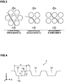
- FIG. 3 is a view illustrating an out-of-plane deformation occurrence portion with respect to the arrangement of the recessed parts 10 of the floor panel in this case.
- a broken line portion in FIG. 3 indicates the out-of-plane deformation occurrence portion, and an arrow in FIG. 3 indicates the direction of a shear force.
- a conventional arrangement (a) is an example in which the recessed parts 10 are arranged in a honeycomb shape, and a conventional arrangement (b) is an example in which four recessed parts 10 are arranged in a square shape.
- the out-of-plane deformation is likely to occur along a direction (hereinafter, an "inclination direction") inclined with respect to the direction of the shear force in the panel member 1 in which the recessed parts 10 are arranged.
- the out-of-plane deformation occurs at a portion relatively low in rigidity of the panel member 1.
- a portion low in rigidity namely, a portion where the recessed part 10 is not formed continues in a wide region in the inclination direction, so that large out-of-plane deformation may occur along the inclination direction.
- the first recessed part group G 1 and the second recessed part group G 2 are arranged in parallel, and therefore a portion low in rigidity does not continue in a wide region in the inclination direction, so that large out-of-plane deformation is less likely to occur.
- large shear buckling becomes less likely to occur in the panel member 1 at collision, thus making it possible to increase the resistance force against the collision in the panel member 1.
- the collision performance of the panel member 1 can be improved.
- the positional relation between the first recessed part group G 1 and the second recessed part group G 2 needs to satisfy predetermined conditions.
- a straight line linking a center of an arbitrary recessed part 10 in the first recessed part group G 1 and a center of the recessed part 10 in the second recessed part group G 2 closest to the recessed part 10 in plan view as illustrated in FIG. 2 is called a "first straight line L 1 ".
- a straight line linking centers of the recessed parts 10 in the first recessed part group G 1 in plan view is called a "second straight line L 2 ".
- the recessed parts 10 of the panel member 1 need to be arranged so that an angle ⁇ formed between the first straight line L 1 and the second straight line L 2 is 80 degrees or more and 100 degrees or less. In the case where the angle ⁇ satisfies this range, the occurrence of large out-of-plane deformation can be suppressed.
- the angle ⁇ formed between the first straight line L 1 and the second straight line L 2 is more preferably 85 degrees or more. Further, the angle ⁇ formed between the first straight line L 1 and the second straight line L 2 is more preferably 95 degrees or less.
- FIG. 4 is a cross-sectional view of the panel member 1 cut to include the centers of the recessed parts 10 adjacent to each other.
- the distance between the recessed parts 10 is expressed by s
- the diameter of the recessed part 10 is expressed by d
- the depth of the recessed part 10 is expressed by h.
- the distance s between the recessed parts 10 is a length of a plane of the panel member 1 where the recessed part 10 is not formed (a length from an R end of one ridge line part to an R end of the other ridge line part) in the cross section cut to include the centers of the adjacent recessed parts 10 as in FIG. 4 .
- the plane where the recessed part 10 is not formed is assumed to be a "reference plane".
- the inter-recessed part distance s is appropriately changed according to the required collision performance, the shape of the panel member 1 or the like, and a distance between the adjacent recessed parts 10 in the first recessed part group G 1 and a distance between the adjacent recessed parts 10 in the second recessed part group G 2 each preferably satisfy s ⁇ 3d/10.
- the distance s between the recessed parts 10 is 3d/10 or less, the effect of suppressing the occurrence of the large out-of-plane deformation can be enhanced.
- the adjacent recessed parts 10 are separated from each other in the reference plane in FIG. 4 .
- “being separated from each other” means that there is no bridge portion or other coupling portion. If the recessed parts 10 are coupled to each other by the coupling portion such as the bridge portion, the length of the side wall (side wall part 10b) of the recessed part 10 decreases by a length corresponding to the coupling portion, thus decreasing the effect of suppressing the occurrence of the large out-of-plane deformation.
- the distance s between the recessed part 10 in the first recessed part group G 1 and the recessed part 10 in the second recessed part group G 2 also satisfies 3d/10 or less.
- the "inter-recessed part distance s" when calculating the distance between the recessed part 10 in the first recessed part group G 1 and the recessed part 10 in the second recessed part group G 2 means the distance between an arbitrary recessed part 10 in the first recessed part group G 1 and a recessed part 10 in the second recessed part group G 2 located at a position closest to the recessed part 10.
- the distances s between the recessed parts 10 in the first recessed part group G 1 are equal to one another, but the distances s between the recessed parts 10 may be different from one another.
- the distances s between the recessed parts 10 in the second recessed part group G 2 are equal to one another, but the distances s between the recessed parts 10 may be different from one another.
- the distances s between the recessed parts 10 in the first recessed part group G 1 and the recessed parts 10 in the second recessed part group G 2 are equal to one another, but the distances s between the recessed parts 10 may be different from one another.
- the distance s between the recessed parts 10 is preferably, for example, 5 mm or more, and preferably equal to or less than the diameter d of the recessed part 10.
- the diameters d of the recessed parts 10 provided in the panel member 1 are equal to one another, but the diameters d of the recessed parts 10 may be different from one another.
- the "diameter d of the recessed part 10" used when calculating the relation between the distance s between the adjacent recessed parts 10 and the diameter d of the recessed part 10 is an average value of the diameters of the adjacent recessed parts 10.
- the value of the diameter d of the recessed part 10 is appropriately changed according to the space around the panel member 1 or the formability of the panel member 1, and is preferably, for example, 3 mm or more and 100 mm or less.
- the depths h of the recessed parts 10 may be similarly different from one another.
- the depth h of the recessed part 10 is preferably 3 mm or more, and more preferably 5 mm or more. Further, the depth of the recessed part 10 is preferably 30 mm or less.
- the recessed part 10 is composed of a bottom part 10a constituting a bottom surface of the recessed part and the side wall part 10b erected around the bottom part 10a.
- An angle formed between the bottom part 10a and the side wall part 10b (hereinafter, an inclination angle ⁇ of the side wall part) is 20 degrees or more and 90 degrees or less, more preferably 45 degrees or more and 90 degrees or less, and furthermore preferably 60 degrees or more.
- the inclination angle ⁇ is an angle closer to 90 degrees, the collision performance of the panel member 1 is improved more.
- the two rows of the recessed parts 10 are arranged in parallel in the embodiment to form the first recessed part group G 1 and the second recessed part group G 2 along the X-direction
- three rows of the recessed parts 10 may be aligned in parallel as illustrated in FIG. 5 to form the first recessed part group G 1 and the second recessed part group G 2 also in the Y-direction. This can enhance the effect of suppressing the occurrence of the out-of-plane deformation due to the shear force.
- the panel member 1 is not limited to the floor panel but may be, for example, a roof panel, a hood inner panel, a back door inner panel or the like.
- a preferable direction for example, the vehicle length direction, the vehicle width direction, the vehicle height direction or the like
- the direction in which the first recessed part group G 1 and the second recessed part group G 2 are formed is appropriately changed according to the place to which the panel member 1 is applied.
- the recessed part 10 may be in a shape recessed when viewed from the vehicle-interior side of the panel member 1 or may be in a shape recessed when viewed from the vehicle-exterior side in the above embodiment, but the recessed parts 10 may have such a configuration that a recessed shape and a projecting shape when viewed from vehicle-interior side exist in a mixed manner.
- the dimensions and configurations of the recessed shape when viewed from the vehicle-interior side and the projecting shape when viewed from the vehicle-exterior side only need to satisfy the conditions explained in the above embodiment.
- the recessed part 10 has been explained to be in a circular shape in plan view in the above embodiment, but does not always need to be in a perfect circular shape but may be in an almost circular shape or an elliptical shape in plan view.
- the value of b/a being a minor/major axis ratio is preferably designed to 1/3 or more and 2 or less, and more preferably designed to 1/2 or more and 2 or less.
- the diameter d of the recessed part explained in the above embodiment only needs to be an average diameter of the minor axis a and the major axis b.
- the floor panel of the analysis model has a depth of the recessed part of 5 mm and a diameter of the recessed part of 64 mm. Further, the inter-recessed part distance in the first recessed part group, the inter-recessed part distance in the second recessed part group, and the distance between the recessed part in the first recessed part group and the recessed part in the second recessed part group are each 14 mm.
- the angle ⁇ ( FIG. 2 ) formed between the first straight line and the second straight line indicating the positional relation between the first recessed part group and the second recessed part group is 90 degrees.
- an analysis model in which the recessed part is not provided with respect to the analysis model in the above inventive example was created as a comparative example, and subjected to a simulation under the same conditions. Further, an analysis model in the case of an angle ⁇ of 60 degrees was created as a comparative example, and subjected to a simulation under the same conditions.
- the vehicle width was set to 170 mm and the vehicle length was set to 250 mm.
- FIG. 6 is a chart illustrating the history of a stress resultant (reaction force) of a floor including a frame occurring at collision of an impactor in the simulation in the comparative example.
- FIG. 7 is a chart illustrating the history of a similar reaction force occurring at collision of an impactor in the simulation in the inventive example.
- the magnitude of the reaction force in a minus region indicates a resistance force against the collision. Note that the history of a load due to the collision reached the floor panel was indicated at 60 ms or later at Time indicated on the horizontal axis in each chart ( FIG. 6 to FIG. 8 ) according to this example.
- the magnitudes of the reaction forces in the vehicle length direction and the vehicle width direction are larger in the inventive example than in the comparative example.
- arranging the recessed parts as in the inventive example can increase the resistance force against the collision as the panel member to increase the energy absorption amount.
- FIG. 8 illustrates the simulation result in the case where the angle ⁇ is 60 degrees, and arranging the recessed parts as in the inventive example can increase the maximum reaction force to improve the collision performance as is clear from the comparison between FIG. 7 and FIG. 8 .
- FIG. 9 is their simulation results. As illustrated in FIG. 9 , when the angle ⁇ falls with a range of 80 degrees or more and 100 degrees or less, the maximum reaction force with respect to the axial force becomes larger than that in the conventional arrangement of the recessed parts to improve the collision performance.
- FIG. 10 a plurality of analysis models different in number of recessed parts in the vehicle length direction of the floor panel were created and subjected to a simulation under the same conditions as those of the above simulation. Their simulation results are illustrated in FIG. 10 .
- the analysis model in which the number of recessed parts is three or more illustrated in FIG. 10 is a model having the "recessed part group" according to the present invention, and has the first recessed part group and the second recessed part group.
- the reaction force in the vehicle width direction in the case where there are three recessed parts in the vehicle length direction is almost twice as much as that in the case where there are two recessed parts, thus providing a significant effect.
- FIG. 11 is a chart illustrating the relation between the value of s/d and the maximum reaction force in the vehicle length direction, and is a graph of the analysis results using the same analysis models as in the above Example 1.
- the analysis results in this example are listed in the following Table 1.
- FIG. 12 is a chart illustrating the relation between the inclination angle ⁇ and the maximum reaction force in the vehicle length direction, and is a graph of the analysis results using the same analysis models as in the above Example 1.
- the analysis results in this example are listed in the following Table 2.
- [Table 2] ⁇ [deg] MAXIMUM REACTION FORCE IN VEHICLE LENGTH DIRECTION[kN] COMPARATIVE EXAMPLE 1 0 14 COMPARATIVE EXAMPLE 2 10 14 INVENTIVE EXAMPLE 12 20 15 INVENTIVE EXAMPLE 13 30 15 INVENTIVE EXAMPLE 14 45 22 INVENTIVE EXAMPLE 15 60 30 INVENTIVE EXAMPLE 16 80 36 INVENTIVE EXAMPLE 17 90 36
- the maximum reaction force in the vehicle length direction slightly increases when the inclination angle ⁇ is 20 degrees or more, the maximum reaction force in the vehicle length direction increases when the inclination angle ⁇ is 45 degrees or more, and the maximum reaction force in the vehicle length direction more significantly increases when the inclination angle ⁇ is 60 degrees or more.
- the inclination angle ⁇ formed between the bottom part and the side wall part of the recessed part according to the present invention is preferably 20 degrees or more, more preferably 45 degrees or more, and furthermore preferably 60 degrees or more as explained in the above embodiment.
- FIG. 13 is a chart illustrating the relation between the minor/major axis ratio b/a and the maximum reaction force in the vehicle length direction in the case where the recessed part shape is in an elliptical shape in plan view in the same analysis model as in the above Example 1.
- the analysis results in this example are listed in the following Table 3.
- the major axis of the recessed part was the vehicle length direction and the minor axis was the vehicle width direction.
- the minor/major axis ratio b/a is preferably designed to 1/3 or more and 2 or less and is more preferably designed to 1/2 or more and 2 or less as explained in the above embodiment.
- the present invention is usable as a panel member such as a floor panel, a roof panel, a hood inner panel, a back door inner panel or the like.
Applications Claiming Priority (2)
| Application Number | Priority Date | Filing Date | Title |
|---|---|---|---|
| JP2018172238 | 2018-09-14 | ||
| PCT/JP2019/036179 WO2020054859A1 (fr) | 2018-09-14 | 2019-09-13 | Élément de panneau |
Publications (2)
| Publication Number | Publication Date |
|---|---|
| EP3838721A1 true EP3838721A1 (fr) | 2021-06-23 |
| EP3838721A4 EP3838721A4 (fr) | 2022-05-18 |
Family
ID=69777738
Family Applications (1)
| Application Number | Title | Priority Date | Filing Date |
|---|---|---|---|
| EP19859952.4A Pending EP3838721A4 (fr) | 2018-09-14 | 2019-09-13 | Élément de panneau |
Country Status (5)
| Country | Link |
|---|---|
| US (1) | US11760423B2 (fr) |
| EP (1) | EP3838721A4 (fr) |
| JP (1) | JP6747615B1 (fr) |
| CN (1) | CN112689594B (fr) |
| WO (1) | WO2020054859A1 (fr) |
Families Citing this family (1)
| Publication number | Priority date | Publication date | Assignee | Title |
|---|---|---|---|---|
| JP7120054B2 (ja) * | 2019-01-29 | 2022-08-17 | トヨタ自動車株式会社 | 車両用構造体及び車両用鋼板の強化方法 |
Family Cites Families (19)
| Publication number | Priority date | Publication date | Assignee | Title |
|---|---|---|---|---|
| JP2530973B2 (ja) * | 1992-04-20 | 1996-09-04 | 新日本製鐵株式会社 | 塗装鮮映性及びプレス成形性の優れた鋼帯 |
| DE19503166C2 (de) * | 1995-02-01 | 1997-03-13 | Thyssen Stahl Ag | Verfahren zur Herstellung von Doppellagenblechen |
| US6682128B2 (en) * | 1998-02-04 | 2004-01-27 | Oakwood Energy Management, Inc. | Composite energy absorber |
| IT1303583B1 (it) * | 1998-12-14 | 2000-11-14 | Delta Di Amidei Dario & C Sas | Metodo per la fabbricazione di componenti tridimensionali a strutturacellulare costituiti da due fogli di lamiera metallica, e relativi |
| US7404593B2 (en) * | 2000-02-07 | 2008-07-29 | Oakwood Energy Management Inc. | Modular energy absorber of varying topography and method for configuring same |
| US20020142129A1 (en) * | 2001-02-21 | 2002-10-03 | Hutsman Corporation | Automotive head impact protection |
| JP4282377B2 (ja) * | 2003-06-04 | 2009-06-17 | 株式会社神戸製鋼所 | 車体パネル構造体 |
| JP4019421B2 (ja) | 2003-08-20 | 2007-12-12 | マツダ株式会社 | 自動車のフロアパネル構造 |
| DE102006000697A1 (de) * | 2005-07-22 | 2007-01-25 | Hong Seong Industrial Co., LTD., Yeoksam | Durch Tiefziehen hergestellter Kern für ein Sandwich-Paneel sowie zugehöriges Sandwich-Paneel |
| JP2008087669A (ja) * | 2006-10-03 | 2008-04-17 | Hayashi Engineering Inc | 車両用衝撃吸収構造体 |
| JP2010023326A (ja) | 2008-07-17 | 2010-02-04 | Fukai Seisakusho:Kk | 合成樹脂製板状体 |
| EP2620353B1 (fr) * | 2010-11-10 | 2015-09-02 | Honda Motor Co., Ltd. | Structure de plancher d'automobile |
| JP6074900B2 (ja) * | 2011-06-21 | 2017-02-08 | Jfeスチール株式会社 | 金属板および自動車用ボディ部品 |
| ES2748867T3 (es) * | 2011-12-20 | 2020-03-18 | Nippon Steel Corp | Panel de piso frontal |
| JP2015189146A (ja) * | 2014-03-28 | 2015-11-02 | 日鐵住金建材株式会社 | 複合構造体及びその製造方法、樹脂構造体 |
| DE112015000089T5 (de) * | 2014-04-23 | 2016-03-03 | Suzuki Motor Corporation | Stoßdämpfer |
| CN203819357U (zh) * | 2014-04-24 | 2014-09-10 | 重庆长安汽车股份有限公司 | 一种汽车前罩内板 |
| DE102014218730A1 (de) * | 2014-09-18 | 2016-03-24 | Ford Global Technologies, Llc | Energieabsorber und Überkopfsystem mit Energieabsorber |
| JP6651318B2 (ja) * | 2015-09-25 | 2020-02-19 | スズキ株式会社 | 車両用フロアパネル |
-
2019
- 2019-09-13 WO PCT/JP2019/036179 patent/WO2020054859A1/fr unknown
- 2019-09-13 CN CN201980060028.5A patent/CN112689594B/zh active Active
- 2019-09-13 US US17/274,090 patent/US11760423B2/en active Active
- 2019-09-13 JP JP2019572243A patent/JP6747615B1/ja active Active
- 2019-09-13 EP EP19859952.4A patent/EP3838721A4/fr active Pending
Also Published As
| Publication number | Publication date |
|---|---|
| CN112689594B (zh) | 2023-09-22 |
| US20210197899A1 (en) | 2021-07-01 |
| EP3838721A4 (fr) | 2022-05-18 |
| CN112689594A (zh) | 2021-04-20 |
| US11760423B2 (en) | 2023-09-19 |
| JP6747615B1 (ja) | 2020-08-26 |
| JPWO2020054859A1 (ja) | 2020-10-22 |
| WO2020054859A1 (fr) | 2020-03-19 |
Similar Documents
| Publication | Publication Date | Title |
|---|---|---|
| CN113544048B (zh) | 用于车辆的门槛结构及其获得方法 | |
| CN109496183B (zh) | 汽车的外装板 | |
| US11279408B2 (en) | Hollow member | |
| EP2837548A1 (fr) | Caisse de véhicule | |
| US11135902B2 (en) | Impact absorption member | |
| US11912341B2 (en) | Automobile hood | |
| EP3838721A1 (fr) | Élément de panneau | |
| KR20140013103A (ko) | 충격 흡수 부재 | |
| JP6973517B2 (ja) | 車両用構造部材 | |
| WO2020085381A1 (fr) | Élément de châssis d'automobile et véhicule électrique | |
| JP2023075317A (ja) | 車体部材 | |
| EP3932750B1 (fr) | Élément structural pour véhicule | |
| US11981370B2 (en) | Structural member for vehicle | |
| JP5237927B2 (ja) | 自動車のルーフ補強部材およびその設計方法 | |
| KR20210069707A (ko) | 골격 부재 | |
| JP7192837B2 (ja) | 車両用構造部材 | |
| JP7376797B2 (ja) | 自動車骨格部材および電気自動車 | |
| WO2020196837A1 (fr) | Élément d'ossature et structure de caisse de véhicule | |
| CN110475706B (zh) | 汽车的冲击吸收构件和纵梁 | |
| JP2023131794A (ja) | 構造部材 | |
| JP2021187433A (ja) | 自動車用構造部材、及びその製造方法 | |
| CN115210095A (zh) | 汽车外装面板的骨架结构 |
Legal Events
| Date | Code | Title | Description |
|---|---|---|---|
| STAA | Information on the status of an ep patent application or granted ep patent |
Free format text: STATUS: THE INTERNATIONAL PUBLICATION HAS BEEN MADE |
|
| PUAI | Public reference made under article 153(3) epc to a published international application that has entered the european phase |
Free format text: ORIGINAL CODE: 0009012 |
|
| STAA | Information on the status of an ep patent application or granted ep patent |
Free format text: STATUS: REQUEST FOR EXAMINATION WAS MADE |
|
| 17P | Request for examination filed |
Effective date: 20210316 |
|
| AK | Designated contracting states |
Kind code of ref document: A1 Designated state(s): AL AT BE BG CH CY CZ DE DK EE ES FI FR GB GR HR HU IE IS IT LI LT LU LV MC MK MT NL NO PL PT RO RS SE SI SK SM TR |
|
| DAV | Request for validation of the european patent (deleted) | ||
| DAX | Request for extension of the european patent (deleted) | ||
| A4 | Supplementary search report drawn up and despatched |
Effective date: 20220414 |
|
| RIC1 | Information provided on ipc code assigned before grant |
Ipc: B62D 21/15 20060101ALI20220408BHEP Ipc: B62D 25/20 20060101AFI20220408BHEP |