EP3838440B1 - Kernherstellungsvorrichtung - Google Patents
Kernherstellungsvorrichtung Download PDFInfo
- Publication number
- EP3838440B1 EP3838440B1 EP20197383.1A EP20197383A EP3838440B1 EP 3838440 B1 EP3838440 B1 EP 3838440B1 EP 20197383 A EP20197383 A EP 20197383A EP 3838440 B1 EP3838440 B1 EP 3838440B1
- Authority
- EP
- European Patent Office
- Prior art keywords
- valve
- kneading vessel
- core
- manufacturing apparatus
- feed port
- Prior art date
- Legal status (The legal status is an assumption and is not a legal conclusion. Google has not performed a legal analysis and makes no representation as to the accuracy of the status listed.)
- Active
Links
Images


Classifications
-
- B—PERFORMING OPERATIONS; TRANSPORTING
- B22—CASTING; POWDER METALLURGY
- B22C—FOUNDRY MOULDING
- B22C5/00—Machines or devices specially designed for dressing or handling the mould material so far as specially adapted for that purpose
- B22C5/02—Dressing by centrifuging essentially or additionally
-
- B—PERFORMING OPERATIONS; TRANSPORTING
- B22—CASTING; POWDER METALLURGY
- B22C—FOUNDRY MOULDING
- B22C15/00—Moulding machines characterised by the compacting mechanism; Accessories therefor
- B22C15/02—Compacting by pressing devices only
- B22C15/06—Compacting by pressing devices only involving mechanical gearings, e.g. crank gears
-
- B—PERFORMING OPERATIONS; TRANSPORTING
- B22—CASTING; POWDER METALLURGY
- B22C—FOUNDRY MOULDING
- B22C5/00—Machines or devices specially designed for dressing or handling the mould material so far as specially adapted for that purpose
- B22C5/04—Machines or devices specially designed for dressing or handling the mould material so far as specially adapted for that purpose by grinding, blending, mixing, kneading, or stirring
- B22C5/0409—Blending, mixing, kneading or stirring; Methods therefor
- B22C5/0413—Horizontal mixing and conveying units, e.g. the unit being rotatable about a vertical axis, or having a supplementary mixing house with a vertical axis at its end
-
- B—PERFORMING OPERATIONS; TRANSPORTING
- B22—CASTING; POWDER METALLURGY
- B22C—FOUNDRY MOULDING
- B22C5/00—Machines or devices specially designed for dressing or handling the mould material so far as specially adapted for that purpose
- B22C5/14—Equipment for storing or handling the dressed mould material, forming part of a plant for preparing such material
-
- B—PERFORMING OPERATIONS; TRANSPORTING
- B22—CASTING; POWDER METALLURGY
- B22C—FOUNDRY MOULDING
- B22C13/00—Moulding machines for making moulds or cores of particular shapes
- B22C13/12—Moulding machines for making moulds or cores of particular shapes for cores
- B22C13/16—Moulding machines for making moulds or cores of particular shapes for cores by pressing through a die
-
- B—PERFORMING OPERATIONS; TRANSPORTING
- B22—CASTING; POWDER METALLURGY
- B22C—FOUNDRY MOULDING
- B22C15/00—Moulding machines characterised by the compacting mechanism; Accessories therefor
- B22C15/02—Compacting by pressing devices only
- B22C15/08—Compacting by pressing devices only involving pneumatic or hydraulic mechanisms
-
- B—PERFORMING OPERATIONS; TRANSPORTING
- B22—CASTING; POWDER METALLURGY
- B22C—FOUNDRY MOULDING
- B22C5/00—Machines or devices specially designed for dressing or handling the mould material so far as specially adapted for that purpose
- B22C5/04—Machines or devices specially designed for dressing or handling the mould material so far as specially adapted for that purpose by grinding, blending, mixing, kneading, or stirring
- B22C5/0409—Blending, mixing, kneading or stirring; Methods therefor
-
- B—PERFORMING OPERATIONS; TRANSPORTING
- B22—CASTING; POWDER METALLURGY
- B22C—FOUNDRY MOULDING
- B22C5/00—Machines or devices specially designed for dressing or handling the mould material so far as specially adapted for that purpose
- B22C5/04—Machines or devices specially designed for dressing or handling the mould material so far as specially adapted for that purpose by grinding, blending, mixing, kneading, or stirring
- B22C5/0409—Blending, mixing, kneading or stirring; Methods therefor
- B22C5/044—Devices having a vertical stirrer shaft in a fixed receptacle
-
- B—PERFORMING OPERATIONS; TRANSPORTING
- B22—CASTING; POWDER METALLURGY
- B22C—FOUNDRY MOULDING
- B22C5/00—Machines or devices specially designed for dressing or handling the mould material so far as specially adapted for that purpose
- B22C5/04—Machines or devices specially designed for dressing or handling the mould material so far as specially adapted for that purpose by grinding, blending, mixing, kneading, or stirring
- B22C5/0409—Blending, mixing, kneading or stirring; Methods therefor
- B22C5/045—Devices having a horizontal stirrer shaft in a fixed receptacle
-
- B—PERFORMING OPERATIONS; TRANSPORTING
- B22—CASTING; POWDER METALLURGY
- B22C—FOUNDRY MOULDING
- B22C5/00—Machines or devices specially designed for dressing or handling the mould material so far as specially adapted for that purpose
- B22C5/04—Machines or devices specially designed for dressing or handling the mould material so far as specially adapted for that purpose by grinding, blending, mixing, kneading, or stirring
- B22C5/0409—Blending, mixing, kneading or stirring; Methods therefor
- B22C5/0472—Parts; Accessories; Controlling; Feeding; Discharging; Proportioning
-
- B—PERFORMING OPERATIONS; TRANSPORTING
- B22—CASTING; POWDER METALLURGY
- B22C—FOUNDRY MOULDING
- B22C5/00—Machines or devices specially designed for dressing or handling the mould material so far as specially adapted for that purpose
- B22C5/12—Machines or devices specially designed for dressing or handling the mould material so far as specially adapted for that purpose for filling flasks
-
- B—PERFORMING OPERATIONS; TRANSPORTING
- B22—CASTING; POWDER METALLURGY
- B22C—FOUNDRY MOULDING
- B22C7/00—Patterns; Manufacture thereof so far as not provided for in other classes
- B22C7/06—Core boxes
-
- B—PERFORMING OPERATIONS; TRANSPORTING
- B22—CASTING; POWDER METALLURGY
- B22C—FOUNDRY MOULDING
- B22C9/00—Moulds or cores; Moulding processes
- B22C9/10—Cores; Manufacture or installation of cores
Definitions
- the present invention relates to a core manufacturing apparatus.
- JP 2019-202323 A discloses a scraper type table feeder.
- CN 204 524 165 U discloses an automatic material conveying device.
- JP H05 164599 A discloses a device for measuring molding sand.
- JP 2015 101462 A discloses a feeder that transports particulate matters by rotating a screw.
- EP 2 602 212 A1 discloses a powder/granular material feeding device.
- a feed port through which core sand is fed is provided on the upper side of the kneading vessel in the horizontally lying state.
- a storage unit e.g., a hopper
- a valve that opens and closes the feed port is provided to prevent moisture inside the kneading vessel from entering a pipe extending from the feed port to the storage unit.
- JP 2019-202323 A requires keeping the storage unit in the same posture, regardless of the posture of the kneading vessel, while the kneading vessel turns from the horizontally lying state to the vertically standing state. This makes it difficult to seal the feed port of the kneading vessel by the same valve both when the kneading vessel is in the horizontally lying state and when it is in the vertically standing state.
- the present invention provides a core manufacturing apparatus in which the feed port of the kneading vessel can be sealed by the same valve both when the kneading vessel is in a horizontally lying state and when it is in a vertically standing state.
- a core manufacturing apparatus of the present invention is specified in claim 1.
- the feed port can be sealed by the same valve both when the kneading vessel is in the horizontally lying state and when it is in the vertically standing state.
- the core manufacturing apparatus may include a parallel linkage having a driver that has the first shaft and the second shaft as joints. With the above configuration, the core manufacturing apparatus is excellent in maintainability.
- the valve may be made of a resin.
- the valve may be in contact with the feed port of which a circumferential edge is covered with a seal member having an annular shape and made of a resin.
- valve and the seal member may be made of different resins. With the above configuration, the adhesion between the valve and the feed port can be reduced.
- annular groove extending along the circumferential edge of the feed port may be provided in the resin seal member, at a side facing an outer circumferential surface of the kneading vessel.
- a rubber packing may be provided between the seal member and an outer circumferential surface of the kneading vessel.
- the valve may have a cut-off spherical shape obtained by cutting off a portion of the valve that does not come into contact with the feed port.
- the valve may have a spherical shape.
- a through-hole perpendicular to the second shaft may be formed inside the valve.
- the storage unit may include a hopper that stores a predetermined amount of core sand to be fed into the kneading vessel, and a weigher configured to measure the weight of the hopper.
- the weigher may be configured to measure the weight of the core sand stored in the hopper while the core sand is supplied to the hopper.
- the storage unit may include a preliminary tank that stores the core sand to be supplied to the hopper, and a valve provided on a pipe connecting the preliminary tank and the hopper to each other.
- the degree of opening of the valve provided on the pipe may be adjusted based on the weight of the hopper measured by the weigher.
- valve configured to open and close the feed port may be made of an abrasion-resistant resin
- the seal member maybe made of an abrasion-resistant resin
- the present invention can provide a core manufacturing apparatus in which the feed port of the kneading vessel can be sealed by the same valve both when the kneading vessel is in the horizontally lying state and when it is in the vertically standing state.
- FIG. 1 is side views showing the actions of the core manufacturing apparatus according to the embodiment.
- the right-handed xyz-orthogonal coordinate system shown in FIG. 1 and the other drawings is for the convenience of illustrating the positional relationship among components. Normally, a z-axis positive direction is a vertically upward direction and an xy-plane is a horizontal plane, which applies to all the drawings.
- the core manufacturing apparatus includes a kneading unit 10, a storage unit 20, and links L1, L2.
- the kneading unit 10 includes a kneading vessel 11 that is fed with core sand and kneads the core sand, a turning support member 13 that supports the kneading vessel 11, and a piston 14 that ejects the kneaded core sand.
- the storage unit 20 includes a preliminary tank 21 that temporarily stores core sand, a weigh hopper 22 that stores, while weighing, a predetermined amount of core sand to be fed into the kneading vessel 11, and a support member 23 that supports the preliminary tank 21 and the weigh hopper 22.
- the kneading vessel 11 is supported so as to be turnable around a shaft (first shaft) A1 by the turning support member 13 through the link L1 fixed on the kneading vessel 11.
- the kneading vessel 11 is capable of transitioning between a horizontally lying state and a vertically standing state by turning 90° around the shaft A1.
- core sand is fed from the weigh hopper 22 into the kneading vessel 11 and the fed core sand is kneaded.
- the core sand is ejected downward (in a z-axis negative direction) and packed into a mold by the piston 14. Shown at the center in FIG. 1 is a state where the kneading vessel 11 is in transition from the horizontally lying state to the vertically standing state or from the vertically standing state to the horizontally lying state.
- the posture of the storage unit 20 depends on the support member 23.
- the support member 23 is coupled to the link L1 so as to be turnable around a shaft (second shaft) A2. Since the link L1 is fixed on the kneading vessel 11, the support member 23 (i.e., the storage unit 20) is coupled to the kneading vessel 11 so as to be turnable around the shaft A2.
- the link L2 is coupled to the turning support member 13 so as to be turnable around a shaft A3 and coupled to the support member 23 so as to be turnable around a shaft A4.
- the turning support member 13, the support member 23, and the links L1, L2 constitute a parallel linkage having the four shafts A1 to A4 as joints.
- the turning support member 13 is fixed on the ground and corresponds to a fixed link in the parallel linkage.
- the link L1 fixed on the kneading vessel 11 corresponds to a driver.
- the link L2 and the support member 23 correspond to a follower and a connector, respectively.
- the core manufacturing apparatus keeps the storage unit 20 coupled to the kneading vessel 11 in the same posture while the kneading vessel 11 turns. It is not necessary to uncouple the storage unit 20 from the kneading vessel 11 when the kneading vessel 11 turns. By thus eliminating the need for uncoupling and coupling actions, this apparatus achieves excellent core productivity.
- the support member 23 may constitute a fixed link and the turning support member 13 may constitute a connector.
- the storage unit 20 is required to be coupled to the kneading vessel 11 so as to be turnable around the shaft A2 parallel to the turning shaft A1 of the kneading vessel 11, and to remain coupled to the kneading vessel 11 in the same posture while the kneading vessel 11 turns.
- the storage unit 20 may be kept in the same posture by connecting the shafts A1, A2 to each other by a belt or a gear instead of the parallel linkage.
- a parallel linkage is less likely to fail when core sand sticks thereto and is excellent in maintainability.
- FIG. 2 to FIG. 4 are sectional views of the core manufacturing apparatus according to the embodiment.
- FIG. 2 and FIG. 3 are sectional views showing states where the kneading vessel 11 is in the horizontally lying state shown on the left side in FIG. 1 .
- FIG. 4 is a sectional view showing a state where the kneading vessel 11 is in the vertically standing state shown on the right side in FIG. 1 .
- the core manufacturing apparatus according to the embodiment includes the kneading unit 10, the storage unit 20, the links L1, L2, and a control unit 30.
- the kneading unit 10 includes the kneading vessel 11, kneading rods 12, the turning support member 13, and the piston 14.
- the kneading vessel 11 is a tubular member that is fed with core sand S1 through a feed port 11a to which the storage unit 20 is coupled.
- the kneading vessel 11 has, for example, a cylindrical shape.
- the feed port 11a is provided on an upper side of the kneading vessel 11 in the horizontally lying state of the kneading vessel 11.
- the core sand S1 can be fed into the kneading vessel 11 by gravity.
- An ejection port 11b through which the kneaded core sand S1 is ejected is provided in one end surface, in a longitudinal direction, of the kneading vessel 11, and the piston 14 is provided on the other end surface.
- the ejection port 11b is provided so as to protrude from the end surface of the kneading vessel 11.
- a core forming mold (not shown) is coupled to the ejection port 11b.
- the core sand S1 fed into the kneading vessel 11 is kneaded along with a binder.
- the core sand S1 may be either natural sand or artificial sand.
- the binder is, for example, an inorganic binder containing liquid glass and water, but may instead be an organic binder.
- the binder is sprayed from a spraying device (not shown) provided on an inner circumferential surface of the kneading vessel 11.
- the spraying device is provided, for example, in the vicinity of the feed port 11a.
- the kneading rods 12 are provided inside the kneading vessel 11 so as to extend along substantially the entire length of the kneading vessel 11 in the longitudinal direction. There is a plurality of kneading rods 12, and these kneading rods 12 are fixed on, for example, a disc-shaped rotating base 12a.
- the rotating base 12a is provided inside the kneading vessel 11, at an end on the side of the piston 14, and rotates around an axis parallel to the longitudinal direction of the kneading vessel 11.
- the core sand S1 fed into the kneading vessel 11 is kneaded by the kneading rods 12.
- the kneading rods 12 are disposed, for example, in a radial arrangement centered on a rotational axis. Alternatively, the kneading rods 12 may be disposed in an S-shape so as to be point-symmetrical with the rotational axis as the center.
- the shape of the kneading rods 12 is not particularly limited as long as it is a columnar shape extending parallel to the rotational axis.
- the cross-sectional shape of the kneading rods 12 is, for example, a circular shape, but may instead be an elliptical shape, a polygonal shape, etc.
- the rotating base 12a is an external gear and driven to rotate by a driving source, such as a motor, through a gear disposed at a circumferential edge of the rotating base 12a.
- a driving source such as a motor
- the operation of this driving source is controlled by, for example, the control unit 30.
- the rotational axis of the rotating base 12a coincides with a central axis of the cylindrical kneading vessel 11 in this embodiment, but the present invention is not particularly limited to this arrangement.
- the kneading vessel 11 is supported so as to be turnable around the shaft (first shaft) A1 by the turning support member 13 through the link L1 fixed on the kneading vessel 11.
- the kneading vessel 11 is capable of transitioning between the horizontally lying state and the vertically standing state by turning 90° around the shaft A1.
- the kneading vessel 11 is driven to rotate by a driving source (not shown), such as a motor, coupled to the shaft A1.
- a driving source such as a motor
- the core sand S1 is fed into the kneading vessel 11 through the feed port 11a located on the upper side of the kneading vessel 11, and the fed core sand S1 is kneaded by the kneading rods 12.
- a valve V2 and a valve V3 to be described later are opened, the core sand S1 stored in the weigh hopper 22 is fed into the kneading vessel 11 by gravity.
- FIG. 2 shows a state where the valve V3 is closed
- FIG. 3 shows a state where the valve V3 is opened.
- the valves V2, V3 are closed except when the core sand S1 is fed.
- the core sand S1 is ejected downward (in the z-axis negative direction) and packed into a mold 40 by the piston 14.
- the mold 40 is composed of an upper mold 41 and a lower mold 42, with a cavity 43 formed therebetween.
- the core sand S1 ejected from the kneading vessel 11 by the piston 14 is packed into the cavity 43 to manufacture a core.
- This core is used, for example, to cast an on-board engine part.
- the piston 14 shown in the drawings is an electrically operated ball-screw piston, and includes a piston head 141, a piston rod 142, and a motor 143.
- the piston head 141 is housed inside the kneading vessel 11 and disposed closer to the ejection port 11b than the rotating base 12a is.
- the piston head 141 is driven by the motor 143 that is coupled to the piston head 141 through the piston rod 142 that extends through the end surface of the kneading vessel 11.
- the operation of the motor 143 is controlled by, for example, the control unit 30.
- the piston head 141 is on standby at an end of the kneading vessel 11 on the side of the piston 14.
- the piston head 141 advances in the longitudinal direction of the kneading vessel 11 and ejects the kneaded core sand S1 through the ejection port 11b.
- the core sand S1 is ejected with the kneading vessel 11 in the vertically standing state.
- FIG. 4 shows a state where the piston head 141 has descended and the core sand S1 has been ejected.
- a plug 11c made of rubber, for example, is mounted at a root of the ejection port 11b, i.e., on an inner end surface of the kneading vessel 11.
- the plug 11c can keep the core sand S1 fed into the kneading vessel 11 from leaking out of the kneading vessel 11.
- the plug 11c has an incision that has, for example, a cross shape as seen in a plan view and extends through a central portion of the plug 11c in a thickness direction thereof. Therefore, the plug 11c opens due to the incision when the core sand S1 inside the kneading vessel 11 is pressurized and ejected.
- the gap between the inner circumferential surface of the kneading vessel 11 and an outer circumferential surface of the piston head 141 is kept sealed by a seal member or the like.
- the piston head 141 has through-holes into which the kneading rods 12 are fitted and inserted.
- the gap between an inner circumferential surface of each of these through-holes and an outer circumferential surface of the kneading rod 12 is also kept sealed by a seal member or the like.
- This configuration allows the core sand S1 inside the kneading vessel 11 to be ejected through the ejection port 11b without leaking.
- the piston head 141 can rotate along with the kneading rods 12. While the piston 14 is an electrically operated piston here, the piston 14 is not limited thereto and may instead be a piston driven by air pressure, oil pressure, or the like.
- the storage unit 20 includes the preliminary tank 21, the weigh hopper 22, the support member 23, pipes P1 to P3, and valves V1 to V3.
- the preliminary tank 21 is a tank that temporarily stores the core sand S1 to be supplied to the weigh hopper 22.
- an upper part of the preliminary tank 21 has a cylindrical shape and a lower part thereof has an inverted conical shape.
- the core sand S1 is supplied to the preliminary tank 21 from a larger storage tank through a pipe etc.
- the preliminary tank 21 and the weigh hopper 22 are connected to each other by the pipe P1.
- the weigh hopper 22 is provided under the preliminary tank 21, and a lower portion of the preliminary tank 21 and an upper portion of the weigh hopper 22 are connected to each other by the pipe P1.
- the pipe P1 is provided with the valve V1.
- the valve V1 When the valve V1 is opened, the core sand S1 stored in the preliminary tank 21 is fed into the weigh hopper 22 by gravity.
- the amount of core sand S1 to be fed can be finely adjusted by adjusting the degree of opening of the valve V1. As will be described later in detail, the degree of opening of the valve V1 is controlled by, for example, the control unit 30.
- the weigh hopper 22 stores a predetermined amount of core sand S1 that has been weighed to be fed into the kneading vessel 11.
- FIG. 5 is a detailed sectional view of the weigh hopper 22.
- the storage unit 20 includes a weigher 24 that measures the weight of the weigh hopper 22, and a weigher support member 25 that supports the weigher 24.
- the core sand S1 stored in the weigh hopper 22 is weighed while the core sand S1 is supplied to the weigh hopper 22.
- the core manufacturing apparatus simultaneously weighs and stores core sand and thereby achieves excellent productivity.
- the weigh hopper 22 includes a main body 221 and a lid 222.
- the main body 221 has an inverted conical shape, and includes a flange 221a that is provided on an outer circumferential surface at an upper portion of the main body 221 and protrudes outward.
- the lid 222 is a disc-shaped cover lid and fits on an upper end portion of the main body 221.
- a through-hole is provided at a central portion of the lid 222, and the pipe P1 is slidably fitted in the through-hole.
- the pipe P2 extends from a lower end of the main body 221. A lower end portion of the pipe P2 is slidably fitted in the pipe P3.
- the pipe P2 is provided with the valve V2.
- the valve V2 and the valve V3 to be described later are opened, the core sand S1 stored in the weigh hopper 22 is fed into the kneading vessel 11 by gravity.
- FIG. 3 shows the state where the valve V3 is opened. Opening and closing of the valve V2 and the valve V3 are controlled by, for example, the control unit 30.
- the weigher 24 is, for example, a load cell and measures the weight of the weigh hopper 22.
- the flange 221a of the weigh hopper 22 is placed on the weigher 24. Specifically, the weigher 24 is loaded with the weights of the weigh hopper 22 (the main body 221 and the lid 222), the core sand S1 inside the weigh hopper 22, the pipe P2, and the valve V2.
- the weigher 24 Since the pipe P1 is slidably fitted in the through-hole of the lid 222 as described above, the weigher 24 is not loaded with the weights of members located above the pipe P1.Since the pipe P2 is slidably fitted in the pipe P3, the weigher 24 is not loaded with the weights of members located under the pipe P3.
- the weight of the core sand S1 fed from the preliminary tank 21 into the weigh hopper 22 can be learned from the weight measured by the weigher 24. For example, based on the weight measured by the weigher 24, the control unit 30 controls the degree of opening of the valve V1 such that the weight of the core sand S1 inside the weigh hopper 22 meets a target value. For example, the control unit 30 decreases the degree of opening of the valve V1 as the weight of the core sand S1 approaches the target value. Under this control, the weight of the core sand S1 to be fed into the weigh hopper 22 can be accurately controlled.
- the weigher support member 25 includes a flat-plate-shaped platform 25a and pillars 25b that support the platform 25a.
- the weigher 24 is placed and fixed on the platform 25a.
- the pillars 25b are fixed on the support member 23. Therefore, the weigher 24 is supported by the support member 23 through the weigher support member 25.
- a through-hole 25c through which the main body 221 of the weigh hopper 22 is inserted is provided at a central portion of the platform 25a.
- the weigher support member 25 supports only the weigher 24 and does not directly support the weigh hopper 22. With this configuration, the weigher 24 is able to measure the weight of the weigh hopper 22.
- the weigher 24 supports the weigh hopper 22 while measuring the weight of the weigh hopper 22. Therefore, the weigher support member 25 supports the weigh hopper 22 through the weigher 24. The support member 23 supports the weigh hopper 22 through the weigher support member 25 and the weigher 24.
- the support member 23 indirectly supports the weigh hopper 22. Similarly, the support member 23 indirectly supports the preliminary tank 21 through a support member (not shown). This is why the posture of the storage unit 20 depends on the support member 23.
- the support member 23 is coupled to the link L1 so as to be turnable around the shaft (second shaft) A2. Since the link L1 is fixed on the kneading vessel 11, the support member 23 is coupled to the kneading vessel 11 so as to be turnable around the shaft A2. The support member 23 is coupled to the link L2 so as to be turnable around the shaft A4. The link L2 is coupled to the turning support member 13 so as to be turnable around the shaft A3.
- the turning support member 13, the support member 23, and the links L1, L2 constitute a parallel linkage having the four shafts A1 to A4 as joints.
- the turning support member 13 is fixed on the ground and corresponds to a fixed link in the parallel linkage.
- the link L1 fixed on the kneading vessel 11 corresponds to a driver.
- the link L2 and the support member 23 correspond to a follower and a connector, respectively.
- the core manufacturing apparatus keeps the storage unit 20 coupled to the kneading vessel 11 in the same posture while the kneading vessel 11 turns. It is not necessary to uncouple the storage unit 20 from the kneading vessel 11 when the kneading vessel 11 turns. By thus eliminating the need for uncoupling and coupling actions, this apparatus achieves excellent core productivity.
- the pipe P3 is fixed on the support member 23.
- the pipe P2 is fitted at one end of the pipe P3 as described above, and the valve V3 is disposed at the other end of the pipe P3.
- the shape of the other end of the pipe P3 is adapted to the surface shape of the valve V3 so as to keep the core sand S1 from leaking.
- the valve V3 is supported by the support member 23 shown in FIG. 1 so as to be turnable around the turning shaft A2 of the support member 23.
- the valve V3 can turn around the shaft A2 relatively to the support member 23, and can also turn around the shaft A2 along with the support member 23 relatively to the kneading vessel 11.
- the valve V3 opens and closes the feed port 11a with the kneading vessel 11 in the horizontally lying state by turning around the shaft A2 relatively to the support member 23 while remaining in contact with the feed port 11a.
- the support member 23 i.e., the storage unit 20
- the support member 23 can maintain the same posture with the valve V3 in contact with the feed port 11a while the kneading vessel 11 turns.
- the feed port 11a can be sealed by the same valve V3 both when the kneading vessel 11 is in the horizontally lying state and when the kneading vessel 11 is in the vertically standing state.
- the turning actions (i.e., opening and closing) of the valve V3 relatively to the support member 23 are controlled by, for example, the control unit 30.
- the valve V3 shown in FIG. 2 to FIG. 4 has a cut-off spherical shape obtained by cutting off, by a plane, a portion of the valve V3 that does not come into contact with the feed port 11a, but may instead have a shape of a perfect sphere.
- This cut-off spherical shape can reduce the size and weight of the valve V3. Since a part of the valve V3 has an arc shape, the feed port 11a has a substantially circular shape.
- the valve V3 is made of a resin, for example, but may instead be made of a metal etc.
- the valve V3 is made of an abrasion-resistant resin, such as fluorine resin, super-high-molecular polyethylene, polyacetal, or polyamide.
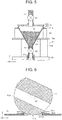
- FIG. 6 is a detailed sectional view of the valve V3 and the feed port 11a.
- FIG. 6 corresponds to an enlarged view of FIG. 2 .
- the valve V3 is in contact with the feed port 11a of which a circumferential edge is covered with a seal member SL1, which has an annular shape and made of a resin. With this configuration, the sealing of the gap between the valve V3 and the feed port 11a is kept.
- the resin seal member SL1 is made of an abrasion-resistant resin, such as fluorine resin, super-high-molecular polyethylene, polyacetal, or polyamide.
- valve V3 and the resin seal member SL1 may be made of different resins.
- the valve V3 may be made of fluorine resin and the resin seal member SL1 may be made of super-high-molecular polyethylene.
- the resin seal member SL1 is provided so as to protrude from the circumferential edge of the feed port 11a toward a center side.
- a portion of the resin seal member SL1 that protrudes toward the center side of the feed port 11a has a triangular cross-sectional shape, with the thickness decreasing gradually toward the center of the feed port 11a. This allows the resin seal member SL1 to come into close contact with the valve V3 easily.
- an annular groove SL1a extending along the circumferential edge of the feed port 11a is provided in the resin seal member SL1, at a side facing the outer circumferential surface of the kneading vessel 11. Since the thickness of the resin seal member SL1 decreases gradually toward the center of the feed port 11a as described above, the groove SL1a also has a triangular cross-sectional shape. A portion of the resin seal member SL1 where the groove SL1a is formed has a substantially constant small thickness and deforms easily. Therefore, the resin seal member SL1 can come easily into close contact with the valve V3 and also easily absorb thermal expansion of the valve V3. Thus, providing the groove SL1a contributes to sealing the gap between the valve V3 and the feed port 11a more effectively.
- a flat-plate-shaped annular rubber packing SL2 is provided between the resin seal member SL1 and the outer circumferential surface of the kneading vessel 11.
- Providing the rubber packing SL2 allows the resin seal member SL1 to come into close contact with the valve V3 more easily and also to absorb thermal expansion of the valve V3.
- the rubber packing SL2 contributes to sealing the gap between the valve V3 and the feed port 11a even more effectively.
- the rubber packing SL2 is made of, for example, silicone rubber.
- a through-hole V3a perpendicular to the turning shaft A2 of the valve V3 is formed inside the valve V3.
- the valve V3 is closed and the feed port 11a of the kneading vessel 11 is closed with the valve V3.
- the valve V3 has opened by turning around the shaft A2 from the state shown in FIG. 2 .
- the pipe P3 and the feed port 11a of the kneading vessel 11 are connected to each other through the through-hole V3a inside the valve V3, so that the core sand S1 can be fed into the kneading vessel 11.
- the valve V3 is closed to thereby keep moisture inside the kneading vessel 11 from entering the pipe P3.
- the control unit 30 shown in FIG. 2 to FIG. 4 controls all actions in the core manufacturing apparatus, including the turning actions of the kneading vessel 11, the rotating actions of the kneading rods 12, the actions of the piston 14, the opening and closing actions of the valves V1 to V3, and adjustment of the degrees of opening of the valves.
- the control unit 30 may be divided into a plurality of units and provided as such.
- the control unit 30 functions as a computer and includes, for example, a computing part, such as a central processing unit (CPU), and a storing part, such as a random-access memory (RAM) or a read-only memory (ROM), that stores various control programs, data, etc.
- a computing part such as a central processing unit (CPU)
- RAM random-access memory
- ROM read-only memory
- the storage unit 20 is coupled to the kneading vessel 11 so as to be turnable around the shaft A2, and the storage unit 20 remains coupled to the kneading vessel 11 in the same posture while the kneading vessel 11 turns. It is not necessary to uncouple the storage unit 20 from the kneading vessel 11 when the kneading vessel 11 turns. By thus eliminating the need for uncoupling and coupling actions, this apparatus achieves excellent core productivity.
- the storage unit 20 includes the valve V3 having a spherical shape or a cut-off spherical shape that opens and closes the feed port 11a with the kneading vessel 11 in the horizontally lying state by turning around the shaft A2 while remaining in contact with the feed port 11a. Therefore, as shown in FIG. 2 and FIG. 4 , the storage unit 20 can maintain the same posture with the valve V3 in contact with the feed port 11a while the kneading vessel 11 turns. Thus, the feed port 11a can be sealed by the same valve V3 both when the kneading vessel 11 is in the horizontally lying state and when the kneading vessel 11 is in the vertically standing state.
Landscapes
- Engineering & Computer Science (AREA)
- Mechanical Engineering (AREA)
- Molds, Cores, And Manufacturing Methods Thereof (AREA)
- Casting Devices For Molds (AREA)
- Processing And Handling Of Plastics And Other Materials For Molding In General (AREA)
Claims (13)
- Kernherstellungsvorrichtung, die Folgendes umfasst:eine Speichereinheit (20), die zum Speichern von Kernsand konfiguriert ist;einen rohrförmigen Knetbehälter (11), der dafür konfiguriert ist, über eine Zuführöffnung (11a), mit der die Speichereinheit (20) verbunden ist, mit dem Kernsand beschickt zu werden;eine Knetstange (12), die im Inneren des Knetbehälters (11) so vorgesehen ist, dass sie sich in einer Längsrichtung des Knetbehälters (11) erstreckt, und die dafür konfiguriert ist, den Kernsand durch Drehen um eine Achse parallel zur Längsrichtung zu kneten; undeinen Kolben (14), der dafür konfiguriert ist, den gekneteten Kernsand von einem Ende des Knetbehälters (11) in der Längsrichtung auszustoßen, wobei:der Knetbehälter (11) dafür konfiguriert ist, zwischen einem horizontal liegenden Zustand und einem vertikal stehenden Zustand durch Drehen um eine erste Welle (A1) überzugehen;der Knetbehälter (11) dafür konfiguriert ist, mit dem Kernsand in dem horizontal liegenden Zustand durch die Zufuhröffnung (11a), die sich an einer Oberseite des Knetbehälters (11) befindet, gespeist zu werden;der Kolben (14) dafür konfiguriert ist, den Kernsand nach unten auszustoßen und den Kernsand in eine Form zu packen, wenn sich der Knetbehälter (11) im vertikal stehenden Zustand befindet;die Speichereinheit (20) ein Ventil (V3) umfasst, das dafür konfiguriert ist, die Zufuhröffnung (11a) durch Drehen um eine zweite Welle (A2) parallel zur ersten Welle (A1), während sie in Kontakt mit der Zuführöffnung (11a) bleibt, zu öffnen und zu schließen, wenn sich der Knetbehälter (11) in dem horizontal liegenden Zustand befindet;ein Teil des Ventils (V3) eine Bogenform aufweist und die Zuführöffnung (11a) eine im Wesentlichen kreisförmige Form aufweist; unddie Speichereinheit (20) mit dem Knetbehälter (11) so gekoppelt ist, dass sie um die zweite Welle (A2) drehbar ist, und dafür konfiguriert ist, die gleiche Stellung mit dem Ventil (V3) in Kontakt mit der Zuführöffnung (11a) beizubehalten, während sich der Knetbehälter (11) dreht.
- Kernherstellungsvorrichtung nach Anspruch 1, die ferner ein Parallelgestänge mit einem Mitnehmer umfasst, der die erste Welle (A1) und die zweite Welle (A2) als Gelenke aufweist.
- Kernherstellungsvorrichtung nach Anspruch 1 oder 2, wobei das Ventil (V3) aus einem Harz hergestellt ist.
- Kernherstellungsvorrichtung nach einem der Ansprüche 1 bis 3, wobei das Ventil (V3) in Kontakt mit der Zuführungsöffnung (11a) steht, von der ein Umfangsrand mit einem Dichtungselement (SL1) bedeckt ist, das eine ringförmige Form aufweist und aus einem Harz hergestellt ist.
- Kernherstellungsvorrichtung nach Anspruch 4, wobei das Ventil (V3) und das Dichtungselement (SL1) aus verschiedenen Harzen hergestellt sind.
- Kernherstellungsvorrichtung nach Anspruch 4 oder 5, wobei in dem Dichtungselement (SL1) an einer Seite, die einer äußeren Umfangsfläche des Knetbehälters (11) zugewandt ist, eine Ringnut (SL1a) vorgesehen ist, die sich entlang des Umfangsrandes der Zuführöffnung (11a) erstreckt.
- Kernherstellungsvorrichtung nach einem der Ansprüche 4 bis 6, wobei eine Gummidichtung (SL2) zwischen dem Dichtungselement (SL1) und einer äußeren Umfangsfläche des Knetbehälters (11) vorgesehen ist.
- Kernherstellungsvorrichtung nach einem der Ansprüche 1 bis 7, wobei das Ventil (V3) eine abgeschnittene Kugelform aufweist, die durch Abschneiden eines Teils des Ventils (V3) erhalten wird, der nicht in Kontakt mit der Zuführöffnung (11a) kommt.
- Kernherstellungsvorrichtung nach einem der Ansprüche 1 bis 7, wobei das Ventil (V3) eine kugelförmige Form aufweist.
- Kernherstellungsvorrichtung nach einem der Ansprüche 1 bis 9, wobei im Inneren des Ventils (V3) ein Durchgangsloch (V3a) senkrecht zum zweiten Schaft (A2) gebildet ist.
- Kernherstellungsvorrichtung nach einem der Ansprüche 1 bis 10, wobei:die Speichereinheit (20) einen Trichter (22), der eine vorbestimmte Menge an Kernsand speichert, der dem Knetbehälter (11) zugeführt werden soll, und eine Waage (24), die dafür konfiguriert ist, ein Gewicht des Trichters (22) zu messen, umfasst; unddie Waage (24) dafür konfiguriert ist, ein Gewicht des in dem Trichter (22) gelagerten Kernsandes zu messen, während der Kernsand dem Trichter (22) zugeführt wird.
- Kernherstellungsvorrichtung nach Anspruch 11, wobei:die Speichereinheit (20) einen Vorbehälter (21), der den Kernsand speichert, der dem Trichter (22) zugeführt werden soll, und ein Ventil (V1), das an einem Rohr vorgesehen ist, das den Vorbehälter (21) und den Trichter (22) miteinander verbindet, umfasst; undwenn der Kernsand von dem Vorbehälter (21) dem Trichter (22) zugeführt wird, ein Öffnungsgrad des Ventils (V1), das an dem Rohr vorgesehen ist, auf der Grundlage des Gewichts des Trichters (22), das durch die Waage (24) gemessen wird, eingestellt wird.
- Kernherstellungsvorrichtung nach einem der Ansprüche 4 bis 12, wobei das Ventil (V3), das zum Öffnen und Schließen der Zuführöffnung (11a) konfiguriert ist, aus einem abriebfesten Harz und das Dichtungselement (SL1) aus einem abriebfesten Harz hergestellt ist.
Priority Applications (1)
| Application Number | Priority Date | Filing Date | Title |
|---|---|---|---|
| PL20197383T PL3838440T3 (pl) | 2019-12-19 | 2020-09-22 | Urządzenie do wytwarzania rdzeni |
Applications Claiming Priority (1)
| Application Number | Priority Date | Filing Date | Title |
|---|---|---|---|
| JP2019228939A JP7188375B2 (ja) | 2019-12-19 | 2019-12-19 | 中子造型装置 |
Publications (2)
| Publication Number | Publication Date |
|---|---|
| EP3838440A1 EP3838440A1 (de) | 2021-06-23 |
| EP3838440B1 true EP3838440B1 (de) | 2021-12-22 |
Family
ID=72613880
Family Applications (1)
| Application Number | Title | Priority Date | Filing Date |
|---|---|---|---|
| EP20197383.1A Active EP3838440B1 (de) | 2019-12-19 | 2020-09-22 | Kernherstellungsvorrichtung |
Country Status (6)
| Country | Link |
|---|---|
| US (1) | US11084088B2 (de) |
| EP (1) | EP3838440B1 (de) |
| JP (1) | JP7188375B2 (de) |
| CN (1) | CN113000796B (de) |
| BR (1) | BR102020020411A2 (de) |
| PL (1) | PL3838440T3 (de) |
Family Cites Families (19)
| Publication number | Priority date | Publication date | Assignee | Title |
|---|---|---|---|---|
| JPS487289Y1 (de) * | 1969-08-16 | 1973-02-24 | ||
| JPS4934284B1 (de) * | 1969-12-16 | 1974-09-13 | ||
| JPS526784B1 (de) * | 1969-12-25 | 1977-02-24 | ||
| JPS4915771Y1 (de) * | 1970-12-23 | 1974-04-20 | ||
| JPS521859Y2 (de) * | 1974-01-28 | 1977-01-17 | ||
| JP2627805B2 (ja) * | 1989-07-10 | 1997-07-09 | 新東工業株式会社 | 鋳物砂の鋳枠への投入装置 |
| JP2918731B2 (ja) | 1991-12-13 | 1999-07-12 | 旭テック株式会社 | 鋳物砂の計量装置 |
| JP2714653B2 (ja) | 1993-10-13 | 1998-02-16 | 大蔵省印刷局長 | スクレーパ式テーブルフィーダ |
| JP2008062284A (ja) * | 2006-09-08 | 2008-03-21 | Nissei Sogyo Kk | 鋳造用成形型の製造装置 |
| JP5959365B2 (ja) | 2011-12-08 | 2016-08-02 | 株式会社クボタ | 粉粒体供給装置 |
| JP2015101462A (ja) | 2013-11-27 | 2015-06-04 | 株式会社カワタ | 供給装置 |
| JP6233187B2 (ja) * | 2014-05-27 | 2017-11-22 | 新東工業株式会社 | 自硬性鋳型造型装置 |
| CN204524165U (zh) | 2015-01-04 | 2015-08-05 | 溧阳市联华机械制造有限公司 | 向覆膜砂混砂机中加辅料的自动加料装置及其电气回路结构 |
| KR101515572B1 (ko) * | 2015-01-20 | 2015-04-29 | 주식회사 디알액시온 | 무기 바인더를 이용한 중자 및 주조품의 제조방법 |
| JP2017131913A (ja) * | 2016-01-26 | 2017-08-03 | トヨタ自動車株式会社 | 混練装置 |
| JP6378223B2 (ja) * | 2016-02-19 | 2018-08-22 | ファナック株式会社 | 射出装置 |
| JP6631654B2 (ja) * | 2018-05-21 | 2020-01-15 | トヨタ自動車株式会社 | 中子造型装置 |
| CN209439402U (zh) * | 2018-11-06 | 2019-09-27 | 天津奥德康科技有限公司 | 一种具有搅拌和报警功能的射芯机加砂机构 |
| CN109986071B (zh) * | 2019-05-15 | 2024-05-10 | 大连科承铸造装备科技有限公司 | 铸造生产线 |
-
2019
- 2019-12-19 JP JP2019228939A patent/JP7188375B2/ja active Active
-
2020
- 2020-09-21 US US17/026,524 patent/US11084088B2/en active Active
- 2020-09-22 EP EP20197383.1A patent/EP3838440B1/de active Active
- 2020-09-22 PL PL20197383T patent/PL3838440T3/pl unknown
- 2020-10-05 BR BR102020020411-4A patent/BR102020020411A2/pt not_active Application Discontinuation
- 2020-12-18 CN CN202011511413.8A patent/CN113000796B/zh active Active
Also Published As
| Publication number | Publication date |
|---|---|
| JP2021094590A (ja) | 2021-06-24 |
| EP3838440A1 (de) | 2021-06-23 |
| US20210187592A1 (en) | 2021-06-24 |
| PL3838440T3 (pl) | 2022-03-28 |
| JP7188375B2 (ja) | 2022-12-13 |
| US11084088B2 (en) | 2021-08-10 |
| CN113000796A (zh) | 2021-06-22 |
| CN113000796B (zh) | 2022-12-13 |
| BR102020020411A2 (pt) | 2021-06-29 |
Similar Documents
| Publication | Publication Date | Title |
|---|---|---|
| EP3838439B1 (de) | Kernherstellungsvorrichtung | |
| KR100500228B1 (ko) | 미세 분말체의 충전 방법 및 충전 장치 | |
| CN102224399B (zh) | 聚合物整理方法 | |
| US20050220497A1 (en) | Apparatus for toner processing including a variable-orifice non-contact valve | |
| US11084088B2 (en) | Core manufacturing apparatus | |
| CN218368403U (zh) | 一种药剂粉末灌装机构及防毒面具药剂灌装设备 | |
| CN214692215U (zh) | 一种铅酸蓄电池铅粉下料缓冲装置 | |
| CN116395170B (zh) | 一种用于粉料的喂料系统及其控制方法 | |
| AU2003248075B2 (en) | Method and device of producing multiple doser for powdered medicine | |
| CN115638857B (zh) | 核电厂放射性废物进料计量装置及方法 | |
| CN218370316U (zh) | 一种双秤连续全程计量失重式加料机 | |
| JPH08192802A (ja) | 粉粒体の容器への充填方法及び装置 | |
| CN223479394U (zh) | 一种食品加工用自动打包装置 | |
| CN223107054U (zh) | 一种提升称重精度的减量称称重组件 | |
| CN218916102U (zh) | 一种烟花生产用填药装置 | |
| CN222973673U (zh) | 一种金属粉末的定量给料机 | |
| CN224163236U (zh) | 一种钡粉称量工具 | |
| CN217573980U (zh) | 一种挤出机供料装置 | |
| CN216935673U (zh) | 一种连铸保护渣制备用原料自动配料系统 | |
| CN213021879U (zh) | 一种混凝土的精确称重装置 | |
| CN222330046U (zh) | 一种密封分装倒料自动化装置 | |
| CN222468981U (zh) | 高精度加料系统 | |
| CN206604461U (zh) | 料仓和物料配比系统 | |
| CN108201862B (zh) | 一种聚烯烃固体催化剂的加料系统 | |
| CN208627248U (zh) | 一种化工生产用自动加料系统 |
Legal Events
| Date | Code | Title | Description |
|---|---|---|---|
| PUAI | Public reference made under article 153(3) epc to a published international application that has entered the european phase |
Free format text: ORIGINAL CODE: 0009012 |
|
| STAA | Information on the status of an ep patent application or granted ep patent |
Free format text: STATUS: REQUEST FOR EXAMINATION WAS MADE |
|
| 17P | Request for examination filed |
Effective date: 20200922 |
|
| AK | Designated contracting states |
Kind code of ref document: A1 Designated state(s): AL AT BE BG CH CY CZ DE DK EE ES FI FR GB GR HR HU IE IS IT LI LT LU LV MC MK MT NL NO PL PT RO RS SE SI SK SM TR |
|
| GRAP | Despatch of communication of intention to grant a patent |
Free format text: ORIGINAL CODE: EPIDOSNIGR1 |
|
| STAA | Information on the status of an ep patent application or granted ep patent |
Free format text: STATUS: GRANT OF PATENT IS INTENDED |
|
| RIC1 | Information provided on ipc code assigned before grant |
Ipc: B22C 5/04 20060101AFI20210715BHEP Ipc: B22C 9/10 20060101ALI20210715BHEP Ipc: B22C 7/06 20060101ALI20210715BHEP Ipc: B22C 13/16 20060101ALI20210715BHEP |
|
| INTG | Intention to grant announced |
Effective date: 20210809 |
|
| RAP3 | Party data changed (applicant data changed or rights of an application transferred) |
Owner name: TOYOTA JIDOSHA KABUSHIKI KAISHA |
|
| GRAS | Grant fee paid |
Free format text: ORIGINAL CODE: EPIDOSNIGR3 |
|
| GRAA | (expected) grant |
Free format text: ORIGINAL CODE: 0009210 |
|
| STAA | Information on the status of an ep patent application or granted ep patent |
Free format text: STATUS: THE PATENT HAS BEEN GRANTED |
|
| AK | Designated contracting states |
Kind code of ref document: B1 Designated state(s): AL AT BE BG CH CY CZ DE DK EE ES FI FR GB GR HR HU IE IS IT LI LT LU LV MC MK MT NL NO PL PT RO RS SE SI SK SM TR |
|
| REG | Reference to a national code |
Ref country code: GB Ref legal event code: FG4D |
|
| REG | Reference to a national code |
Ref country code: CH Ref legal event code: EP |
|
| REG | Reference to a national code |
Ref country code: DE Ref legal event code: R096 Ref document number: 602020001376 Country of ref document: DE |
|
| REG | Reference to a national code |
Ref country code: AT Ref legal event code: REF Ref document number: 1456745 Country of ref document: AT Kind code of ref document: T Effective date: 20220115 |
|
| REG | Reference to a national code |
Ref country code: IE Ref legal event code: FG4D |
|
| REG | Reference to a national code |
Ref country code: LT Ref legal event code: MG9D |
|
| PG25 | Lapsed in a contracting state [announced via postgrant information from national office to epo] |
Ref country code: RS Free format text: LAPSE BECAUSE OF FAILURE TO SUBMIT A TRANSLATION OF THE DESCRIPTION OR TO PAY THE FEE WITHIN THE PRESCRIBED TIME-LIMIT Effective date: 20211222 Ref country code: LT Free format text: LAPSE BECAUSE OF FAILURE TO SUBMIT A TRANSLATION OF THE DESCRIPTION OR TO PAY THE FEE WITHIN THE PRESCRIBED TIME-LIMIT Effective date: 20211222 Ref country code: FI Free format text: LAPSE BECAUSE OF FAILURE TO SUBMIT A TRANSLATION OF THE DESCRIPTION OR TO PAY THE FEE WITHIN THE PRESCRIBED TIME-LIMIT Effective date: 20211222 Ref country code: BG Free format text: LAPSE BECAUSE OF FAILURE TO SUBMIT A TRANSLATION OF THE DESCRIPTION OR TO PAY THE FEE WITHIN THE PRESCRIBED TIME-LIMIT Effective date: 20220322 |
|
| REG | Reference to a national code |
Ref country code: NL Ref legal event code: MP Effective date: 20211222 |
|
| REG | Reference to a national code |
Ref country code: AT Ref legal event code: MK05 Ref document number: 1456745 Country of ref document: AT Kind code of ref document: T Effective date: 20211222 |
|
| PG25 | Lapsed in a contracting state [announced via postgrant information from national office to epo] |
Ref country code: SE Free format text: LAPSE BECAUSE OF FAILURE TO SUBMIT A TRANSLATION OF THE DESCRIPTION OR TO PAY THE FEE WITHIN THE PRESCRIBED TIME-LIMIT Effective date: 20211222 Ref country code: NO Free format text: LAPSE BECAUSE OF FAILURE TO SUBMIT A TRANSLATION OF THE DESCRIPTION OR TO PAY THE FEE WITHIN THE PRESCRIBED TIME-LIMIT Effective date: 20220322 Ref country code: LV Free format text: LAPSE BECAUSE OF FAILURE TO SUBMIT A TRANSLATION OF THE DESCRIPTION OR TO PAY THE FEE WITHIN THE PRESCRIBED TIME-LIMIT Effective date: 20211222 Ref country code: HR Free format text: LAPSE BECAUSE OF FAILURE TO SUBMIT A TRANSLATION OF THE DESCRIPTION OR TO PAY THE FEE WITHIN THE PRESCRIBED TIME-LIMIT Effective date: 20211222 Ref country code: GR Free format text: LAPSE BECAUSE OF FAILURE TO SUBMIT A TRANSLATION OF THE DESCRIPTION OR TO PAY THE FEE WITHIN THE PRESCRIBED TIME-LIMIT Effective date: 20220323 |
|
| PG25 | Lapsed in a contracting state [announced via postgrant information from national office to epo] |
Ref country code: NL Free format text: LAPSE BECAUSE OF FAILURE TO SUBMIT A TRANSLATION OF THE DESCRIPTION OR TO PAY THE FEE WITHIN THE PRESCRIBED TIME-LIMIT Effective date: 20211222 |
|
| PG25 | Lapsed in a contracting state [announced via postgrant information from national office to epo] |
Ref country code: SM Free format text: LAPSE BECAUSE OF FAILURE TO SUBMIT A TRANSLATION OF THE DESCRIPTION OR TO PAY THE FEE WITHIN THE PRESCRIBED TIME-LIMIT Effective date: 20211222 Ref country code: SK Free format text: LAPSE BECAUSE OF FAILURE TO SUBMIT A TRANSLATION OF THE DESCRIPTION OR TO PAY THE FEE WITHIN THE PRESCRIBED TIME-LIMIT Effective date: 20211222 Ref country code: RO Free format text: LAPSE BECAUSE OF FAILURE TO SUBMIT A TRANSLATION OF THE DESCRIPTION OR TO PAY THE FEE WITHIN THE PRESCRIBED TIME-LIMIT Effective date: 20211222 Ref country code: PT Free format text: LAPSE BECAUSE OF FAILURE TO SUBMIT A TRANSLATION OF THE DESCRIPTION OR TO PAY THE FEE WITHIN THE PRESCRIBED TIME-LIMIT Effective date: 20220422 Ref country code: ES Free format text: LAPSE BECAUSE OF FAILURE TO SUBMIT A TRANSLATION OF THE DESCRIPTION OR TO PAY THE FEE WITHIN THE PRESCRIBED TIME-LIMIT Effective date: 20211222 Ref country code: EE Free format text: LAPSE BECAUSE OF FAILURE TO SUBMIT A TRANSLATION OF THE DESCRIPTION OR TO PAY THE FEE WITHIN THE PRESCRIBED TIME-LIMIT Effective date: 20211222 Ref country code: CZ Free format text: LAPSE BECAUSE OF FAILURE TO SUBMIT A TRANSLATION OF THE DESCRIPTION OR TO PAY THE FEE WITHIN THE PRESCRIBED TIME-LIMIT Effective date: 20211222 |
|
| PG25 | Lapsed in a contracting state [announced via postgrant information from national office to epo] |
Ref country code: AT Free format text: LAPSE BECAUSE OF FAILURE TO SUBMIT A TRANSLATION OF THE DESCRIPTION OR TO PAY THE FEE WITHIN THE PRESCRIBED TIME-LIMIT Effective date: 20211222 |
|
| REG | Reference to a national code |
Ref country code: DE Ref legal event code: R097 Ref document number: 602020001376 Country of ref document: DE |
|
| PG25 | Lapsed in a contracting state [announced via postgrant information from national office to epo] |
Ref country code: IS Free format text: LAPSE BECAUSE OF FAILURE TO SUBMIT A TRANSLATION OF THE DESCRIPTION OR TO PAY THE FEE WITHIN THE PRESCRIBED TIME-LIMIT Effective date: 20220422 |
|
| PLBE | No opposition filed within time limit |
Free format text: ORIGINAL CODE: 0009261 |
|
| STAA | Information on the status of an ep patent application or granted ep patent |
Free format text: STATUS: NO OPPOSITION FILED WITHIN TIME LIMIT |
|
| PG25 | Lapsed in a contracting state [announced via postgrant information from national office to epo] |
Ref country code: DK Free format text: LAPSE BECAUSE OF FAILURE TO SUBMIT A TRANSLATION OF THE DESCRIPTION OR TO PAY THE FEE WITHIN THE PRESCRIBED TIME-LIMIT Effective date: 20211222 Ref country code: AL Free format text: LAPSE BECAUSE OF FAILURE TO SUBMIT A TRANSLATION OF THE DESCRIPTION OR TO PAY THE FEE WITHIN THE PRESCRIBED TIME-LIMIT Effective date: 20211222 |
|
| 26N | No opposition filed |
Effective date: 20220923 |
|
| PG25 | Lapsed in a contracting state [announced via postgrant information from national office to epo] |
Ref country code: MC Free format text: LAPSE BECAUSE OF FAILURE TO SUBMIT A TRANSLATION OF THE DESCRIPTION OR TO PAY THE FEE WITHIN THE PRESCRIBED TIME-LIMIT Effective date: 20211222 |
|
| REG | Reference to a national code |
Ref country code: BE Ref legal event code: MM Effective date: 20220930 |
|
| PG25 | Lapsed in a contracting state [announced via postgrant information from national office to epo] |
Ref country code: IT Free format text: LAPSE BECAUSE OF FAILURE TO SUBMIT A TRANSLATION OF THE DESCRIPTION OR TO PAY THE FEE WITHIN THE PRESCRIBED TIME-LIMIT Effective date: 20211222 |
|
| P01 | Opt-out of the competence of the unified patent court (upc) registered |
Effective date: 20230427 |
|
| REG | Reference to a national code |
Ref country code: DE Ref legal event code: R084 Ref document number: 602020001376 Country of ref document: DE |
|
| PG25 | Lapsed in a contracting state [announced via postgrant information from national office to epo] |
Ref country code: LU Free format text: LAPSE BECAUSE OF NON-PAYMENT OF DUE FEES Effective date: 20220922 |
|
| PG25 | Lapsed in a contracting state [announced via postgrant information from national office to epo] |
Ref country code: IE Free format text: LAPSE BECAUSE OF NON-PAYMENT OF DUE FEES Effective date: 20220922 |
|
| PG25 | Lapsed in a contracting state [announced via postgrant information from national office to epo] |
Ref country code: BE Free format text: LAPSE BECAUSE OF NON-PAYMENT OF DUE FEES Effective date: 20220930 |
|
| PG25 | Lapsed in a contracting state [announced via postgrant information from national office to epo] |
Ref country code: CY Free format text: LAPSE BECAUSE OF FAILURE TO SUBMIT A TRANSLATION OF THE DESCRIPTION OR TO PAY THE FEE WITHIN THE PRESCRIBED TIME-LIMIT Effective date: 20211222 |
|
| REG | Reference to a national code |
Ref country code: CH Ref legal event code: PL |
|
| PG25 | Lapsed in a contracting state [announced via postgrant information from national office to epo] |
Ref country code: MK Free format text: LAPSE BECAUSE OF FAILURE TO SUBMIT A TRANSLATION OF THE DESCRIPTION OR TO PAY THE FEE WITHIN THE PRESCRIBED TIME-LIMIT Effective date: 20211222 Ref country code: HU Free format text: LAPSE BECAUSE OF FAILURE TO SUBMIT A TRANSLATION OF THE DESCRIPTION OR TO PAY THE FEE WITHIN THE PRESCRIBED TIME-LIMIT; INVALID AB INITIO Effective date: 20200922 |
|
| PG25 | Lapsed in a contracting state [announced via postgrant information from national office to epo] |
Ref country code: TR Free format text: LAPSE BECAUSE OF FAILURE TO SUBMIT A TRANSLATION OF THE DESCRIPTION OR TO PAY THE FEE WITHIN THE PRESCRIBED TIME-LIMIT Effective date: 20211222 |
|
| PG25 | Lapsed in a contracting state [announced via postgrant information from national office to epo] |
Ref country code: CH Free format text: LAPSE BECAUSE OF NON-PAYMENT OF DUE FEES Effective date: 20230930 |
|
| PG25 | Lapsed in a contracting state [announced via postgrant information from national office to epo] |
Ref country code: CH Free format text: LAPSE BECAUSE OF NON-PAYMENT OF DUE FEES Effective date: 20230930 |
|
| PG25 | Lapsed in a contracting state [announced via postgrant information from national office to epo] |
Ref country code: MT Free format text: LAPSE BECAUSE OF FAILURE TO SUBMIT A TRANSLATION OF THE DESCRIPTION OR TO PAY THE FEE WITHIN THE PRESCRIBED TIME-LIMIT Effective date: 20211222 |
|
| PGFP | Annual fee paid to national office [announced via postgrant information from national office to epo] |
Ref country code: DE Payment date: 20250730 Year of fee payment: 6 |
|
| PGFP | Annual fee paid to national office [announced via postgrant information from national office to epo] |
Ref country code: PL Payment date: 20250729 Year of fee payment: 6 |
|
| PGFP | Annual fee paid to national office [announced via postgrant information from national office to epo] |
Ref country code: GB Payment date: 20250731 Year of fee payment: 6 |
|
| PGFP | Annual fee paid to national office [announced via postgrant information from national office to epo] |
Ref country code: FR Payment date: 20250808 Year of fee payment: 6 |
|
| PG25 | Lapsed in a contracting state [announced via postgrant information from national office to epo] |
Ref country code: SI Free format text: LAPSE BECAUSE OF FAILURE TO SUBMIT A TRANSLATION OF THE DESCRIPTION OR TO PAY THE FEE WITHIN THE PRESCRIBED TIME-LIMIT Effective date: 20211222 |