EP3837583B1 - Zylindrischer antrieb unterbaugruppe mit flexurbasiertem linearen führungsmechanismus - Google Patents
Zylindrischer antrieb unterbaugruppe mit flexurbasiertem linearen führungsmechanismus Download PDFInfo
- Publication number
- EP3837583B1 EP3837583B1 EP20781017.7A EP20781017A EP3837583B1 EP 3837583 B1 EP3837583 B1 EP 3837583B1 EP 20781017 A EP20781017 A EP 20781017A EP 3837583 B1 EP3837583 B1 EP 3837583B1
- Authority
- EP
- European Patent Office
- Prior art keywords
- flexures
- longitudinal axis
- ring
- axial
- actuator subassembly
- Prior art date
- Legal status (The legal status is an assumption and is not a legal conclusion. Google has not performed a legal analysis and makes no representation as to the accuracy of the status listed.)
- Active
Links
Images



Classifications
-
- G—PHYSICS
- G02—OPTICS
- G02B—OPTICAL ELEMENTS, SYSTEMS OR APPARATUS
- G02B7/00—Mountings, adjusting means, or light-tight connections, for optical elements
- G02B7/02—Mountings, adjusting means, or light-tight connections, for optical elements for lenses
- G02B7/04—Mountings, adjusting means, or light-tight connections, for optical elements for lenses with mechanism for focusing or varying magnification
-
- A—HUMAN NECESSITIES
- A61—MEDICAL OR VETERINARY SCIENCE; HYGIENE
- A61B—DIAGNOSIS; SURGERY; IDENTIFICATION
- A61B1/00—Instruments for performing medical examinations of the interior of cavities or tubes of the body by visual or photographical inspection, e.g. endoscopes; Illuminating arrangements therefor
- A61B1/00163—Optical arrangements
- A61B1/00188—Optical arrangements with focusing or zooming features
-
- G—PHYSICS
- G03—PHOTOGRAPHY; CINEMATOGRAPHY; ANALOGOUS TECHNIQUES USING WAVES OTHER THAN OPTICAL WAVES; ELECTROGRAPHY; HOLOGRAPHY
- G03B—APPARATUS OR ARRANGEMENTS FOR TAKING PHOTOGRAPHS OR FOR PROJECTING OR VIEWING THEM; APPARATUS OR ARRANGEMENTS EMPLOYING ANALOGOUS TECHNIQUES USING WAVES OTHER THAN OPTICAL WAVES; ACCESSORIES THEREFOR
- G03B13/00—Viewfinders; Focusing aids for cameras; Means for focusing for cameras; Autofocus systems for cameras
- G03B13/32—Means for focusing
- G03B13/34—Power focusing
- G03B13/36—Autofocus systems
-
- G—PHYSICS
- G03—PHOTOGRAPHY; CINEMATOGRAPHY; ANALOGOUS TECHNIQUES USING WAVES OTHER THAN OPTICAL WAVES; ELECTROGRAPHY; HOLOGRAPHY
- G03B—APPARATUS OR ARRANGEMENTS FOR TAKING PHOTOGRAPHS OR FOR PROJECTING OR VIEWING THEM; APPARATUS OR ARRANGEMENTS EMPLOYING ANALOGOUS TECHNIQUES USING WAVES OTHER THAN OPTICAL WAVES; ACCESSORIES THEREFOR
- G03B3/00—Focusing arrangements of general interest for cameras, projectors or printers
- G03B3/10—Power-operated focusing
-
- G—PHYSICS
- G03—PHOTOGRAPHY; CINEMATOGRAPHY; ANALOGOUS TECHNIQUES USING WAVES OTHER THAN OPTICAL WAVES; ELECTROGRAPHY; HOLOGRAPHY
- G03B—APPARATUS OR ARRANGEMENTS FOR TAKING PHOTOGRAPHS OR FOR PROJECTING OR VIEWING THEM; APPARATUS OR ARRANGEMENTS EMPLOYING ANALOGOUS TECHNIQUES USING WAVES OTHER THAN OPTICAL WAVES; ACCESSORIES THEREFOR
- G03B5/00—Adjustment of optical system relative to image or object surface other than for focusing
-
- G—PHYSICS
- G03—PHOTOGRAPHY; CINEMATOGRAPHY; ANALOGOUS TECHNIQUES USING WAVES OTHER THAN OPTICAL WAVES; ELECTROGRAPHY; HOLOGRAPHY
- G03B—APPARATUS OR ARRANGEMENTS FOR TAKING PHOTOGRAPHS OR FOR PROJECTING OR VIEWING THEM; APPARATUS OR ARRANGEMENTS EMPLOYING ANALOGOUS TECHNIQUES USING WAVES OTHER THAN OPTICAL WAVES; ACCESSORIES THEREFOR
- G03B2205/00—Adjustment of optical system relative to image or object surface other than for focusing
- G03B2205/0053—Driving means for the movement of one or more optical element
Definitions
- the present invention is inherent to a cylindrical actuator subassembly with a flexure-based linear guidance mechanism that finds particularly advantageous application when there is an element to be moved along a specific and well defined axis. More specifically, the actuator takes up a cylindrical space except for a smaller cylindrical space which is taken up by the element to be moved along the axis of the cylinder.
- the actuator is typically meant to move an optical lens (e.g. in an endoscopic instrument or an autofocus module) but it may be used for any application where a cylindrical actuator is required.
- At least one actuating member e.g. a shape memory alloy wire
- the lever provides a rotational movement around its fixed end such that a first translational component of said movement is used to move the lens along the cylinder axis, but the rotational movement also results in a second translational component in a direction perpendicular to the cylinder axis which must be limited as much as possible by the guidance mechanism.
- Properly designed and optimized flexure-based guidance mechanisms for actuators may achieve high stiffness and load capacity while simultaneously essentially neutralizing the parasitic errors bringing them to a minimal degree, such as out-of-plan motion, tilting errors and crosstalk.
- the minimization of parasitic errors in such a way as to not affect system performance and reliability is of key importance in applications such as autofocus camera modules, optical lens movement in endoscopic instruments, syringe actuators, cylindrical valves actuators.
- flexures in actuators and micro-actuators are simply as restoring force opposing a movement imparted by an actuating member, or as biasing means.
- camera module control is exemplified in the international patent applications WO 2007113478 , WO 2009056822 , WO 2010012991 and WO 2019008522 , the latter being in the applicant's name.
- the flexure role is passive, i.e. it does not cause the movement of a movable element (lens carrier) but reacts to it.
- a flexure-based linear guidance mechanism is described in US 2018/0031088 describing the use of a set of four flexures to achieve linear displacement of an actuator plate, wherein each flexure is composed of two parallel flexure elements joined together and provided with pleats or arcs for an extension length.
- a first pair of flexures extend and are connected in a first direction between a base plate and an overlying actuator plate that are both L-shaped, while a second pair of flexures extend and are connected in a second direction between the base plate and the actuator plate, said second direction being perpendicular to said first direction.
- Such a guidance mechanism is quite bulky, since it also contains an electric motor as actuating member, and results in a parallelepipedal device.
- Flexure-based actuators are also known from US 9651772 , describing an arrangement for actuation in an optical system relying onto two separate actuator units for paired flexures, that differently from the present invention aims at providing a tilting of optical elements rather than a linear displacement along a specific axis.
- US 7239107 describes the use of foldable flexures in the form of multi-bar linkages engaged by an actuator for x-y plane positioning adjustments, whereas the use of flat piezoelectric flexures in a parallelogram configuration is described in DE 4405501 .
- a conventional cylindrical actuator subassembly is disclosed in US 2013/208369 A1 .
- the purpose of the present invention is to provide a cylindrical actuator subassembly with a flexure-based linear guidance mechanism by making use of flexures having a simple structure and capable to cause displacement only along a predetermined axis with essentially no spurious or secondary movement in any other direction.
- This purpose is achieved by means of a subassembly according to the main clai, the optical system of claim 7, the camera module of claim 8, while other advantageous features are recited in the dependent claims.
- the system includes a first lever arm 1 and a second lever arm 1' extending perpendicularly (in their rest position) to the longitudinal axis A of the cylindrical actuator subassembly.
- Said levers 1, 1' are fixedly pivoted at a first end and mutually connected at a free second end by an axial guidance member 2, that is provided with a transverse base member 3 on which a movable element 4 (runner) is mounted for a linear motion along said longitudinal axis A.
- levers 1, 1' also tends to move runner 4 in a transverse direction, that in the illustrated example is to the left since the levers are pivoted at their left ends.
- the two transverse lever arms 1, 1' form a virtual parallelogram with the axial guidance member 2, said parallelogram being flexible in its corners C1-C4 that represent virtual rotation points (black dots), of which points C1 and C3 are fixed whereas points C2 and C4 are mobile with the mobile sides of the parallelogram.
- the driving force is provided by at least one actuating member (not shown) secured between a fixed position and one of the levers 1, 1' so as to generate an amplified stroke of the guidance member 2.
- the constructive challenge is to create a rotation point in a very small space and the solution provided in the present invention is the use of a flexure system including at least four flexures, each flexure being combined with another flexure and/or a lever to achieve a rotation point by forming an angle that ranges from 0° to 180°.
- the perpendicular stiffness of the guidance mechanism (i.e. the resistance in a direction perpendicular to the direction of the axial movement of runner 4) is smallest for an angle of 0°/180°, which means that a movement of the levers in the transverse direction is also possible, whereas it is highest for an angle of 90°, which means that a movement of the levers in the transverse direction is almost not possible, and is obviously at an intermediate level for any angle value that is in between such as 45°/135°.
- the system preferably includes two axial flexures and two inclined flexures, namely two transverse flexures, i.e. at angles substantially equal to 90°, or two diagonal flexures, i.e. at angles substantially different from 90°.
- the diagram of Fig.2 shows a first embodiment of a guidance mechanism with 90° angles between the flexures (at rest) for maximum stiffness, such that the application of a force F to the second lever 1' results in a movement M of the movable element 4 that is substantially only axial, with a negligible transverse component in the direction perpendicular to axis A.
- the diagram of Fig.2 also shows that the guidance member 2 is a flexure, same as a second guidance member 2' and two transverse flexures 6, 6' that form angles of 90° with the axial flexures 2, 2' when in the rest position.
- the two axial flexures 2, 2' connect the two levers 1, 1' at the end portions thereof on their facing sides, said flexures 2, 2' being also respectively provided with a base 3 that carries runner 4 and with a corresponding base member 3'. Said bases 3, 3' are respectively connected at their radially distal ends to a mobile axial member 5 and to a fixed axial member 5'.
- the two transverse flexures 6, 6' connect the two axial members 5, 5' at the end portions thereof on their facing sides, said flexures 6, 6' passing also respectively through a holder 1a formed on the middle portion of the first lever 1 and a corresponding holder 1a' of the second lever 1'.
- the virtual rotation points C1-C4 are approximately located at the points of virtual intersection of flexures 2, 2' with flexures 6, 6' when the flexures are elongated, i.e. in the rest position.
- lever parallelogram guidance mechanism is explained above in a two-dimensional way with reference to figures 1 and 2 , the available space in a cylindrical actuator has a cylindrical shape whereby a straight lever and a straight transverse flexure as shown in said figures are almost impossible, whereas the axial flexures may remain straight, therefore said levers and transverse flexures can be modified to take a ring shape.
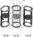
- a first ring-shaped lever 11 and a second ring-shaped lever 11' have an internal diameter and are axially spaced such that two axial members 15, 15' are comprised within the internal cylindrical space defined by levers 11, 11'.
- two axial flexures 12, 12' connect the two ring-shaped levers 11, 11' at opposite peripheral portions thereof on their facing sides, said axial flexures 12, 12' being also respectively provided with bases 13, 13' through which said axial members 15, 15' are secured at radially internal positions with respect to the axial flexures 12, 12'.
- a movable element 14 is carried by base 13, and two ring-shaped transverse flexures 16, 16' extending parallel to the two ring-shaped levers 11, 11' connect the two axial members 15, 15' at the end portions thereof.
- Said transverse flexures 16, 16' pass also respectively through two holders 11a formed on opposite middle portions of the first lever 11 and through two corresponding holders 11a' of the second lever 11', the middle portions being defined as those equally spaced from the axial flexures 12, 12'.
- Dotted circles C1-C4 represent the virtual rotation points defined between the straight axial flexures 12, 12' (parallel to the cylindrical actuator subassembly axis A) and the circular transverse flexures 16, 16' (at 90° angles with respect to said axis A in the rest position of Fig.3A ). It is important to underline that in this case the axial and inclined flexures do not contact each other but are anyway “coupled” to form the corners of the lever parallelogram, “coupled” meaning that the maximum radial distance between the straight axial flexures and the circular transverse flexures is not more than half of the radial distance between the axial flexures and the cylinder axis A (i.e. substantially half of the radius of the cylindrical actuator subassembly 100). Note that there is no minimum distance, i.e. actual contact between the axial and inclined flexures is possible.
- the "coupling" points C1-C4 define a "virtual parallelogram" that by virtue of the bending (straight flexures 12, 12') or inclination (circular flexures 16, 16') of the flexures guides the movable element 14 into a substantially axial displacement when an actuating member causes the rotation of one of the ring-shaped levers as indicated by the arrows in the corresponding figures 3B and 3C showing the system in different actuation states.
- the flexures guide the movable element 14 into respectively an axial upward ( Fig.3B ) or downward ( Fig.3C ) displacement.
- the diagram of Fig.4 shows a second embodiment of a guidance mechanism with 45° angles between the flexures (at rest), all four of which in this case extend between the two levers 1, 1' and are engaged by bases 3, 3' that have a much greater radial extension with respect to the diagram of Fig.2 .
- the two axial flexures 2, 2' connect the two levers 1, 1' in the same manner as in the first embodiment described above in Fig.2
- two diagonal flexures 7, 7' connect the two levers 1, 1' at the same points of the axial flexures 2, 2' but engaging bases 3, 3' at a radially internal end thereof that is close to the cylinder axis A.
- the diagonal flexures 7, 7' have the same role of the circular transverse flexures 16, 16' of the previous embodiment, and they are subjected to the same "coupling" distance constraints to achieve the virtual rotation points C1-C4 that are located at the points of intersection of flexures 2, 2' with flexures 7, 7' where they connect at the ends of levers 1, 1'.
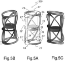
- a first ring-shaped lever 21 and a second ring-shaped lever 21' have an internal diameter and are axially spaced such that a movable element 24 is comprised within the internal cylindrical space defined by levers 21, 21'.
- This movable element 24 is carried by a base 23 extending circumferentially to an almost semi-circular shape same as a corresponding base 23' on the opposite side of the mechanism, said bases 23, 23' extending symmetrically from two opposite axial flexures 22, 22' that connect the two ring-shaped levers 21, 21' at opposite peripheral portions thereof on their facing sides, similarly to the first embodiment shown in Fig.3A .
- Two elliptical diagonal flexures 27, 27' also connect the two ring-shaped levers 21, 21' at the same portions thereof, said diagonal flexures 27, 27' being also respectively engaged by bases 23, 23' but at the end portions thereof rather than at the middle portion where the axial flexures 22, 22' are located.
- the two halves of the diagonal flexures 27, 27' form angles of about 45° with the axial flexures 22, 22' but smaller angles could be formed by suitably changing the position at which the diagonal flexures 27, 27' are engaged by bases 23, 23'.
- the shape of the inclined flexures is preferably chosen from circular, linear, polygonal, elliptical or paired semi-elliptical, i.e. rather than being a closed ellipse it could also be made by two half ellipses individually extending between a lever and a base.
- the movable element 24 is shown in a preferred but not mandatory median position and also in this case the coupling points C1-C4 define a "virtual parallelogram" that by virtue of bending (straight flexures 22, 22') or bending/inclination (elliptical flexures 27, 27') of the flexures guides the movable element 24 into a substantially axial displacement when an actuating member causes the rotation of one of the ring-shaped levers as indicated by the arrows in the corresponding figures 5B and 5C showing the system in different actuation states.
- the flexures guide the movable element 24 into respectively an axial upward ( Fig.5B ) or downward ( Fig.5C ) displacement.
- cylindrical actuator subassembly incorporates a linear guidance mechanism with the following features:
- substantially parallel in the context of the present invention shall be interpreted in a real environment sense, and it will encompass also elements with a negligible variation from the ideal definition of parallel, i.e. elements forming a ⁇ 5° angle.
- the preferred embodiments include two opposite axial straight flexures, both substantially parallel to the cylinder axis, and two inclined flexures extending either transversely with a circular shape ( Fig.3A ) or diagonally at 45° with an elliptical shape ( Fig.5A ).
- the elliptical flexures 27, 27' could be replaced by two half ellipses individually extending between a lever 21, 21' and a base 23, 23'.
- one or both of the circular flexures 16, 16' could be replaced by two half circles individually extending between an axial member 15, 15' and a holder 11a, 11a' whereby the total number of flexures could increase to five or six with any type of inclined flexures.
- Such a modification could also be applied to one or both of the axial straight flexures 12, 12' or 22, 22' that could be replaced by two half flexures individually extending between a lever 11, 11' or 21, 21' and a base 13, 13' or 23, 23'.
- the combination of these possible modifications could increase the total number of flexures to any number between five and eight.
- an essential feature of the present invention is the presence of at least eight flexure elements, defined as flexible elements extending between two rigid parts, that can be made as separate flexures with each flexure corresponding to a flexure element or combined into a smaller number of flexures with one or more flexures corresponding to a plurality of flexure elements.
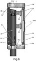
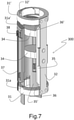
- Figures 6 and 7 respectively show a side view and a perspective view of an actuator subassembly 300 for lenses focus regulation according to the first embodiment of the present invention, namely comprising a first ring-shaped lever 31 and a second ring-shaped lever 31' that have an internal diameter and are axially spaced such that two axial members 35, 35' are comprised within the internal cylindrical space defined by levers 31, 31'.
- the fixed axial member 35' differently from the fixed axial member 15' shown in figures 3A-3C , extends axially beyond the first lever 31 and also circumferentially with a partial side wall up to the cylinder axis A, although in a further embodiment it might comprise a continuous side wall up to the mobile axial member 35.
- Two axial flexures 32, 32' connect the two ring-shaped levers 31, 31' at opposite peripheral portions thereof on their peripheral sides, said axial flexures 32, 32' being also respectively connected to axial members 35, 35' at radially distal portions thereof.
- Two lenses 34 that make up a double movable element are carried by respective bases 33 which in this case are mounted on the mobile axial member 35, whereas the fixed axial member 35' has no base in this case.
- Two ring-shaped transverse flexures 36, 36' extending parallel to the two ring-shaped levers 31, 31' connect the two axial members 35, 35' at the end portions thereof, also passing respectively through two holders 31a formed on opposite middle portions of the first lever 31 and through two corresponding holders 31a' of the second lever 31'.
- the actuating member consists of a shape memory alloy (SMA) wire 37 that is secured between the first lever 31 and a crimp 38 that is externally mounted on the fixed axial member 35.
- SMA shape memory alloy
- VCM voice coil motors
- the actuator subassembly can include a plurality of actuating members at different positions, preferably in antagonistic configuration for a balanced actuation.
- preferred materials are aluminum, harmonic steel, superelastic nitinol and Ni-Ti based superelastic alloys including one or more of copper, titanium-copper alloys and flexible plastic materials.
Landscapes
- Physics & Mathematics (AREA)
- General Physics & Mathematics (AREA)
- Health & Medical Sciences (AREA)
- Life Sciences & Earth Sciences (AREA)
- Surgery (AREA)
- Optics & Photonics (AREA)
- Engineering & Computer Science (AREA)
- Medical Informatics (AREA)
- Radiology & Medical Imaging (AREA)
- Nuclear Medicine, Radiotherapy & Molecular Imaging (AREA)
- Biophysics (AREA)
- Biomedical Technology (AREA)
- Heart & Thoracic Surgery (AREA)
- Pathology (AREA)
- Molecular Biology (AREA)
- Animal Behavior & Ethology (AREA)
- General Health & Medical Sciences (AREA)
- Public Health (AREA)
- Veterinary Medicine (AREA)
- Lens Barrels (AREA)
- Transmission Devices (AREA)
- Studio Devices (AREA)
Claims (8)
- Zylindrische Betätigungsanordnung (100; 200; 300) mit einer Längsachse (A) und umfassend:- ein entlang der Längsachse (A) bewegliches Element (14; 24; 34),- mindestens ein Betätigungselement, das geeignet ist, die Verschiebung des beweglichen Elements (14; 24; 34) zu bewirken, und- einen Führungsmechanismus, der geeignet ist, das bewegliche Element (14; 24; 34) bei seiner Verschiebung entlang der Längsachse (A) zu führen und jede andere Art von Bewegung zu minimieren,dadurch gekennzeichnet,- dass der Führungsmechanismus umfasst:- einen ersten ringförmigen Hebel (11; 21; 31) und einen zweiten ringförmigen Hebel (11'; 21'; 31'), die parallel zueinander sind und in einer entsprechenden Position entlang ihrer jeweiligen Umfänge fest geschwenkt sind,- mindestens zwei gerade axiale Biegungen (12, 12'; 22, 22'; 32, 32'), die im Wesentlichen parallel zur Längsachse (A) sind, und den ersten ringförmigen Hebel (11; 21; 31) und den zweiten ringförmigen Hebel (11'; 21'; 31') an ihren gegenüberliegenden Umfangspositionen verbinden, wobei eine erste gerade axiale Biegung (12; 22; 32) an einer Position angeordnet ist, die der festen Schwenkposition der ringförmigen Hebel (11, 11'; 21, 21'; 31, 31') gegenüberliegt, um mit diesen ein virtuelles Parallelogramm zu bilden, das in seinen Ecken (C1, C2, C3, C4) flexibel ist, die virtuelle Rotationspunkte darstellen, von denen zwei Rotationspunkte (C1, C3) fest sind und zwei Rotationspunkte (C2, C4) entlang der Richtung der Längsachse (A) beweglich sind,- mindestens zwei Biegungen (16, 16'; 27, 27'; 36, 36'), die in Bezug auf die Längsachse (A) geneigt sind und zwischen zwei der virtuellen Drehpunkte (C1, C2, C3, C4) verlaufen,- mindestens zwei Sockel (13, 13'; 23, 23'; 33, 33'), wobei ein erster Sockel (13; 23; 33) das bewegliche Element (14; 24; 34) trägt und entweder direkt oder indirekt an dem ersten geraden axialen Biegeelement (12; 22; 32) angebracht ist, und wobei die axialen Biegungen und die geneigten Biegungen derart gekoppelt sind, dass der radiale Abstand an den virtuellen Drehpunkten (C1, C2, C3, C4) zwischen den mindestens zwei geraden axialen Biegungen (12, 12'; 22, 22'; 32, 32') und den mindestens zwei geneigten Biegungen (16, 16'; 27, 27'; 36, 36') in einem Bereich von Null bis die Hälfte des radialen Abstands zwischen den mindestens zwei geraden axialen Biegungen (12, 12'; 22, 22'; 32, 32') und der Längsachse (A) liegt,- und dass das mindestens eine Betätigungselement zwischen einer festen Position und dem ersten ringförmigen Hebel (11; 21; 31) oder dem zweiten ringförmigen Hebel (11'; 21'; 31') befestigt ist, um eine Kraft in einer Richtung parallel zur Längsachse (A) und an einer Position auszuüben, die im Wesentlichen in der Nähe der festen Schwenkposition des ersten ringförmigen Hebels (11; 21; 31) und des zweiten ringförmigen Hebels (11'; 21'; 31')liegt, wobei die Kraft zu einer Bewegung der beiden beweglichen Drehpunkte (C2, C4) entlang der Richtung der Längsachse (A) und zu einer Änderung der Neigung der mindestens zwei geneigten Biegungen (16, 16'; 27, 27'; 36, 36') in Bezug auf die Längsachse (A) führt.
- Zylindrische Betätigungsanordnung (100; 200; 300) nach Anspruch 1, wobei sie außerdem mindestens zwei axiale Teile (15, 15'; 35, 35') umfasst, die sich zwischen dem ersten ringförmigen Hebel (11; 21; 31) und dem zweiten ringförmigen Hebel (11'; 21'; 31') erstrecken, und die an den mindestens zwei Sockeln (13, 13'; 23, 23'; 33, 33') oder an den mindestens zwei geraden axialen Biegungen (12, 12'; 22, 22'; 32, 32') in einer radial inneren Position in Bezug auf letztere befestigt sind.
- Zylindrische Betätigungsanordnung (100; 200; 300) nach Anspruch 1 oder 2, wobei die Form eines oder mehrerer geneigter Biegungen (16, 16'; 27, 27'; 36, 36') ausgewählt ist aus kreisförmig, linear, polygonal, elliptisch oder gepaart halb-elliptisch oder gepaart halb-kreisförmig.
- Zylindrische Betätigungsanordnung (100; 200; 300) nach einem der vorhergehenden Ansprüche, wobei die mindestens zwei geneigten Biegungen (16, 16'; 36, 36') senkrecht zur Längsachse (A) sind und mit dem ersten ringförmigen Hebel (11; 31) oder zweiten ringförmigen Hebel (11'; 31') durch zwei Halterungen (11a, 11a'; 31a, 31a') verbunden sind, die an gegenüberliegenden mittleren Abschnitten davon ausgebildet sind.
- Zylindrische Betätigungsanordnung (100; 200; 300) nach einem der Ansprüche 1 bis 3, wobei die mindestens zwei geneigten Biegungen (27, 27') einen Winkel von etwa 45° mit den mindestens zwei geraden axialen Biegungen (22, 22') bilden.
- Zylindrische Betätigungsanordnung (100; 200; 300) nach dem vorhergehenden Anspruch, wobei sich die mindestens zwei Sockel (23, 23') in Umfangsrichtung zu einer nahezu halbkreisförmigen Form erstrecken und die mindestens zwei geneigten Biegungen (27, 27') mit den Sockel (23, 23') an deren Endabschnitten in Eingriff stehen.
- Optisches System mit einer zylindrischen Betätigungsanordnung (100; 200; 300) nach einem der vorhergehenden Ansprüche.
- Kameramodul oder medizinisches Diagnoseinstrument, vorzugsweise ein Endoskop, das ein optisches System nach Anspruch 7 enthält.
Applications Claiming Priority (2)
| Application Number | Priority Date | Filing Date | Title |
|---|---|---|---|
| IT201900017843 | 2019-10-03 | ||
| PCT/EP2020/077604 WO2021064149A1 (en) | 2019-10-03 | 2020-10-01 | Cylindrical actuator subassembly with flexure-based linear guidance mechanism |
Publications (2)
| Publication Number | Publication Date |
|---|---|
| EP3837583A1 EP3837583A1 (de) | 2021-06-23 |
| EP3837583B1 true EP3837583B1 (de) | 2022-02-09 |
Family
ID=69191195
Family Applications (1)
| Application Number | Title | Priority Date | Filing Date |
|---|---|---|---|
| EP20781017.7A Active EP3837583B1 (de) | 2019-10-03 | 2020-10-01 | Zylindrischer antrieb unterbaugruppe mit flexurbasiertem linearen führungsmechanismus |
Country Status (5)
| Country | Link |
|---|---|
| US (1) | US11513310B2 (de) |
| EP (1) | EP3837583B1 (de) |
| JP (1) | JP7475437B2 (de) |
| KR (1) | KR102692772B1 (de) |
| WO (1) | WO2021064149A1 (de) |
Families Citing this family (2)
| Publication number | Priority date | Publication date | Assignee | Title |
|---|---|---|---|---|
| GB2603121B (en) * | 2021-01-21 | 2026-04-22 | Thermoteknix Systems Ltd | Camera with flexure focus mechanism |
| CN116974033B (zh) * | 2023-09-25 | 2023-12-15 | 季华实验室 | 一种致动装置、变焦镜头和相机 |
Family Cites Families (20)
| Publication number | Priority date | Publication date | Assignee | Title |
|---|---|---|---|---|
| DE4405501C1 (de) | 1994-02-21 | 1995-06-22 | Fraunhofer Ges Forschung | Piezoelektrische Verstellvorrichtung |
| US6870114B2 (en) | 2001-03-12 | 2005-03-22 | Joseph W. Cole | Method and apparatus for removing and replacing bulb of push-button type electrical switch |
| KR100526250B1 (ko) * | 2003-11-04 | 2005-11-08 | 삼성전기주식회사 | 압전 굴곡변위형 액츄에이터를 사용하는 렌즈 이송장치 및 렌즈 모듈 |
| JP4677533B2 (ja) * | 2005-01-21 | 2011-04-27 | シコー株式会社 | レンズ駆動装置 |
| US7239107B1 (en) | 2006-02-24 | 2007-07-03 | The Board Of Trustees Of The University Of Illinois | Flexure stage |
| KR101353158B1 (ko) | 2006-03-30 | 2014-01-22 | 캠브리지 메카트로닉스 리미티드 | 카메라 렌즈 작동 장치 |
| CN101896719A (zh) | 2007-10-30 | 2010-11-24 | 剑桥机电有限公司 | 形状记忆合金致动装置 |
| WO2010012991A2 (en) | 2008-07-30 | 2010-02-04 | Cambridge Mechatronics Limited | Shape memory alloy actuation apparatus |
| CN102375292B (zh) | 2010-08-20 | 2016-05-11 | 林小军 | 控制光学系统倾斜或转动中心的装置及致动器 |
| KR101932795B1 (ko) * | 2012-05-25 | 2018-12-26 | 캠브리지 메카트로닉스 리미티드 | 형상 기억 합금 작동 장치 |
| GB201221306D0 (en) * | 2012-11-27 | 2013-01-09 | Cambridge Mechatronics Ltd | Suspension system for a camera lens element |
| DE102013204305A1 (de) | 2013-03-13 | 2014-09-18 | Carl Zeiss Smt Gmbh | Anordnung zur Aktuierung wenigstens eines Elementes in einem optischen System |
| CH709292A3 (de) | 2014-02-20 | 2015-10-15 | Miniswys Sa | Positioniervorrichtung für einen Bildstabilisator. |
| WO2015173363A1 (de) * | 2014-05-14 | 2015-11-19 | Carl Zeiss Smt Gmbh | Projektionsbelichtungsanlage mit feldnahem manipulator |
| KR101712849B1 (ko) * | 2014-08-04 | 2017-03-22 | 주식회사 액트로 | 손떨림 보정용 ois 액츄에이터 |
| US9933689B2 (en) * | 2015-05-05 | 2018-04-03 | Actuator Solutions GmbH | Tilt module subassembly and optical image stabilizer comprising it |
| US10295028B2 (en) | 2016-07-26 | 2019-05-21 | Blockwise Engineering Llc | Linear actuator |
| CN108088359B (zh) * | 2016-11-21 | 2019-07-26 | 清华大学 | 便携式轮廓仪及轮廓扫描显微镜和系统 |
| IT201700074728A1 (it) | 2017-07-04 | 2019-01-04 | Actuator Solutions GmbH | Attuatore per auto-focus di modulo di fotocamera |
| US11226469B2 (en) * | 2017-10-30 | 2022-01-18 | Tdk Taiwan Corp. | Optical driving mechanism |
-
2020
- 2020-10-01 US US17/635,498 patent/US11513310B2/en active Active
- 2020-10-01 JP JP2022515739A patent/JP7475437B2/ja active Active
- 2020-10-01 KR KR1020227007370A patent/KR102692772B1/ko active Active
- 2020-10-01 WO PCT/EP2020/077604 patent/WO2021064149A1/en not_active Ceased
- 2020-10-01 EP EP20781017.7A patent/EP3837583B1/de active Active
Non-Patent Citations (1)
| Title |
|---|
| SRIDHAR KOTA ET AL: "Tailoring Unconventional Actuators Using Compliant Transmissions: Design Methods and Applications", IEEE / ASME TRANSACTIONS ON MECHATRONICS, IEEE SERVICE CENTER, PISCATAWAY, NJ, US, vol. 4, no. 4, 1 December 1999 (1999-12-01), XP011034529, ISSN: 1083-4435 * |
Also Published As
| Publication number | Publication date |
|---|---|
| JP2022550679A (ja) | 2022-12-05 |
| EP3837583A1 (de) | 2021-06-23 |
| WO2021064149A1 (en) | 2021-04-08 |
| KR102692772B1 (ko) | 2024-08-08 |
| JP7475437B2 (ja) | 2024-04-26 |
| US20220342277A1 (en) | 2022-10-27 |
| KR20220071186A (ko) | 2022-05-31 |
| US11513310B2 (en) | 2022-11-29 |
Similar Documents
| Publication | Publication Date | Title |
|---|---|---|
| US12480480B2 (en) | Shape memory alloy apparatus | |
| EP3697725B1 (de) | Mems-aktuator mit fünf freiheitsgraden für autofokussierung, optische bildstabilisierung und hochauflösende abbildung bei miniaturkameras | |
| US6785437B2 (en) | Beam-steering optical switching apparatus | |
| US11513310B2 (en) | Cylindrical actuator subassembly with flexure-based linear guidance mechanism | |
| US6698201B1 (en) | Cascaded bimorph rotary actuator | |
| CN115398301B (zh) | 致动器组件 | |
| EP4707899A2 (de) | Abstimmbares prisma | |
| WO2021111131A1 (en) | Actuator assembly | |
| US20250059959A1 (en) | Actuator assembly | |
| US20100033835A1 (en) | Optical lens displacement systems | |
| US20230161226A1 (en) | Actuator assembly | |
| TW201523034A (zh) | 光學設備和方法 | |
| CN106452163B (zh) | 多方向致动器 | |
| CN119790227A (zh) | 致动器组件 | |
| CN120513348A (zh) | 致动器组件 | |
| JPH06328374A (ja) | マイクロマニピュレータ | |
| EP2574969B1 (de) | Optisches Faserpositionierungssystem | |
| WO2021209766A1 (en) | Actuator assembly | |
| JP2004280355A (ja) | 移動装置およびそれを用いた位置決め装置 | |
| EP3274744B1 (de) | Linse mit variablem fokus | |
| CN222415098U (zh) | 致动器组件和相机模块 | |
| CN114902103A (zh) | 致动装置 | |
| WO2023099924A1 (en) | Sma actuator assembly | |
| JPH08318482A (ja) | 関節機構およびこれを用いたマイクロマニピュレータ | |
| KR20250095357A (ko) | 다기능 이동형 소프트 로봇 |
Legal Events
| Date | Code | Title | Description |
|---|---|---|---|
| STAA | Information on the status of an ep patent application or granted ep patent |
Free format text: STATUS: UNKNOWN |
|
| STAA | Information on the status of an ep patent application or granted ep patent |
Free format text: STATUS: THE INTERNATIONAL PUBLICATION HAS BEEN MADE |
|
| PUAI | Public reference made under article 153(3) epc to a published international application that has entered the european phase |
Free format text: ORIGINAL CODE: 0009012 |
|
| STAA | Information on the status of an ep patent application or granted ep patent |
Free format text: STATUS: REQUEST FOR EXAMINATION WAS MADE |
|
| 17P | Request for examination filed |
Effective date: 20210317 |
|
| AK | Designated contracting states |
Kind code of ref document: A1 Designated state(s): AL AT BE BG CH CY CZ DE DK EE ES FI FR GB GR HR HU IE IS IT LI LT LU LV MC MK MT NL NO PL PT RO RS SE SI SK SM TR |
|
| GRAP | Despatch of communication of intention to grant a patent |
Free format text: ORIGINAL CODE: EPIDOSNIGR1 |
|
| STAA | Information on the status of an ep patent application or granted ep patent |
Free format text: STATUS: GRANT OF PATENT IS INTENDED |
|
| INTG | Intention to grant announced |
Effective date: 20210823 |
|
| RIN1 | Information on inventor provided before grant (corrected) |
Inventor name: SCHUMM, TOBIAS Inventor name: BOBIC, NEVEN |
|
| GRAS | Grant fee paid |
Free format text: ORIGINAL CODE: EPIDOSNIGR3 |
|
| GRAA | (expected) grant |
Free format text: ORIGINAL CODE: 0009210 |
|
| STAA | Information on the status of an ep patent application or granted ep patent |
Free format text: STATUS: THE PATENT HAS BEEN GRANTED |
|
| AK | Designated contracting states |
Kind code of ref document: B1 Designated state(s): AL AT BE BG CH CY CZ DE DK EE ES FI FR GB GR HR HU IE IS IT LI LT LU LV MC MK MT NL NO PL PT RO RS SE SI SK SM TR |
|
| DAV | Request for validation of the european patent (deleted) | ||
| DAX | Request for extension of the european patent (deleted) | ||
| REG | Reference to a national code |
Ref country code: GB Ref legal event code: FG4D |
|
| REG | Reference to a national code |
Ref country code: CH Ref legal event code: EP Ref country code: AT Ref legal event code: REF Ref document number: 1467868 Country of ref document: AT Kind code of ref document: T Effective date: 20220215 |
|
| REG | Reference to a national code |
Ref country code: DE Ref legal event code: R096 Ref document number: 602020001816 Country of ref document: DE |
|
| REG | Reference to a national code |
Ref country code: IE Ref legal event code: FG4D |
|
| REG | Reference to a national code |
Ref country code: LT Ref legal event code: MG9D |
|
| REG | Reference to a national code |
Ref country code: NL Ref legal event code: MP Effective date: 20220209 |
|
| REG | Reference to a national code |
Ref country code: AT Ref legal event code: MK05 Ref document number: 1467868 Country of ref document: AT Kind code of ref document: T Effective date: 20220209 |
|
| PG25 | Lapsed in a contracting state [announced via postgrant information from national office to epo] |
Ref country code: SE Free format text: LAPSE BECAUSE OF FAILURE TO SUBMIT A TRANSLATION OF THE DESCRIPTION OR TO PAY THE FEE WITHIN THE PRESCRIBED TIME-LIMIT Effective date: 20220209 Ref country code: RS Free format text: LAPSE BECAUSE OF FAILURE TO SUBMIT A TRANSLATION OF THE DESCRIPTION OR TO PAY THE FEE WITHIN THE PRESCRIBED TIME-LIMIT Effective date: 20220209 Ref country code: PT Free format text: LAPSE BECAUSE OF FAILURE TO SUBMIT A TRANSLATION OF THE DESCRIPTION OR TO PAY THE FEE WITHIN THE PRESCRIBED TIME-LIMIT Effective date: 20220609 Ref country code: NO Free format text: LAPSE BECAUSE OF FAILURE TO SUBMIT A TRANSLATION OF THE DESCRIPTION OR TO PAY THE FEE WITHIN THE PRESCRIBED TIME-LIMIT Effective date: 20220509 Ref country code: NL Free format text: LAPSE BECAUSE OF FAILURE TO SUBMIT A TRANSLATION OF THE DESCRIPTION OR TO PAY THE FEE WITHIN THE PRESCRIBED TIME-LIMIT Effective date: 20220209 Ref country code: LT Free format text: LAPSE BECAUSE OF FAILURE TO SUBMIT A TRANSLATION OF THE DESCRIPTION OR TO PAY THE FEE WITHIN THE PRESCRIBED TIME-LIMIT Effective date: 20220209 Ref country code: HR Free format text: LAPSE BECAUSE OF FAILURE TO SUBMIT A TRANSLATION OF THE DESCRIPTION OR TO PAY THE FEE WITHIN THE PRESCRIBED TIME-LIMIT Effective date: 20220209 Ref country code: ES Free format text: LAPSE BECAUSE OF FAILURE TO SUBMIT A TRANSLATION OF THE DESCRIPTION OR TO PAY THE FEE WITHIN THE PRESCRIBED TIME-LIMIT Effective date: 20220209 Ref country code: BG Free format text: LAPSE BECAUSE OF FAILURE TO SUBMIT A TRANSLATION OF THE DESCRIPTION OR TO PAY THE FEE WITHIN THE PRESCRIBED TIME-LIMIT Effective date: 20220509 |
|
| PG25 | Lapsed in a contracting state [announced via postgrant information from national office to epo] |
Ref country code: PL Free format text: LAPSE BECAUSE OF FAILURE TO SUBMIT A TRANSLATION OF THE DESCRIPTION OR TO PAY THE FEE WITHIN THE PRESCRIBED TIME-LIMIT Effective date: 20220209 Ref country code: LV Free format text: LAPSE BECAUSE OF FAILURE TO SUBMIT A TRANSLATION OF THE DESCRIPTION OR TO PAY THE FEE WITHIN THE PRESCRIBED TIME-LIMIT Effective date: 20220209 Ref country code: GR Free format text: LAPSE BECAUSE OF FAILURE TO SUBMIT A TRANSLATION OF THE DESCRIPTION OR TO PAY THE FEE WITHIN THE PRESCRIBED TIME-LIMIT Effective date: 20220510 Ref country code: FI Free format text: LAPSE BECAUSE OF FAILURE TO SUBMIT A TRANSLATION OF THE DESCRIPTION OR TO PAY THE FEE WITHIN THE PRESCRIBED TIME-LIMIT Effective date: 20220209 Ref country code: AT Free format text: LAPSE BECAUSE OF FAILURE TO SUBMIT A TRANSLATION OF THE DESCRIPTION OR TO PAY THE FEE WITHIN THE PRESCRIBED TIME-LIMIT Effective date: 20220209 |
|
| PG25 | Lapsed in a contracting state [announced via postgrant information from national office to epo] |
Ref country code: IS Free format text: LAPSE BECAUSE OF FAILURE TO SUBMIT A TRANSLATION OF THE DESCRIPTION OR TO PAY THE FEE WITHIN THE PRESCRIBED TIME-LIMIT Effective date: 20220609 |
|
| PG25 | Lapsed in a contracting state [announced via postgrant information from national office to epo] |
Ref country code: SM Free format text: LAPSE BECAUSE OF FAILURE TO SUBMIT A TRANSLATION OF THE DESCRIPTION OR TO PAY THE FEE WITHIN THE PRESCRIBED TIME-LIMIT Effective date: 20220209 Ref country code: SK Free format text: LAPSE BECAUSE OF FAILURE TO SUBMIT A TRANSLATION OF THE DESCRIPTION OR TO PAY THE FEE WITHIN THE PRESCRIBED TIME-LIMIT Effective date: 20220209 Ref country code: RO Free format text: LAPSE BECAUSE OF FAILURE TO SUBMIT A TRANSLATION OF THE DESCRIPTION OR TO PAY THE FEE WITHIN THE PRESCRIBED TIME-LIMIT Effective date: 20220209 Ref country code: EE Free format text: LAPSE BECAUSE OF FAILURE TO SUBMIT A TRANSLATION OF THE DESCRIPTION OR TO PAY THE FEE WITHIN THE PRESCRIBED TIME-LIMIT Effective date: 20220209 Ref country code: DK Free format text: LAPSE BECAUSE OF FAILURE TO SUBMIT A TRANSLATION OF THE DESCRIPTION OR TO PAY THE FEE WITHIN THE PRESCRIBED TIME-LIMIT Effective date: 20220209 Ref country code: CZ Free format text: LAPSE BECAUSE OF FAILURE TO SUBMIT A TRANSLATION OF THE DESCRIPTION OR TO PAY THE FEE WITHIN THE PRESCRIBED TIME-LIMIT Effective date: 20220209 |
|
| REG | Reference to a national code |
Ref country code: DE Ref legal event code: R097 Ref document number: 602020001816 Country of ref document: DE |
|
| PG25 | Lapsed in a contracting state [announced via postgrant information from national office to epo] |
Ref country code: AL Free format text: LAPSE BECAUSE OF FAILURE TO SUBMIT A TRANSLATION OF THE DESCRIPTION OR TO PAY THE FEE WITHIN THE PRESCRIBED TIME-LIMIT Effective date: 20220209 |
|
| PLBE | No opposition filed within time limit |
Free format text: ORIGINAL CODE: 0009261 |
|
| STAA | Information on the status of an ep patent application or granted ep patent |
Free format text: STATUS: NO OPPOSITION FILED WITHIN TIME LIMIT |
|
| 26N | No opposition filed |
Effective date: 20221110 |
|
| PG25 | Lapsed in a contracting state [announced via postgrant information from national office to epo] |
Ref country code: MC Free format text: LAPSE BECAUSE OF FAILURE TO SUBMIT A TRANSLATION OF THE DESCRIPTION OR TO PAY THE FEE WITHIN THE PRESCRIBED TIME-LIMIT Effective date: 20220209 |
|
| REG | Reference to a national code |
Ref country code: BE Ref legal event code: MM Effective date: 20221031 |
|
| P01 | Opt-out of the competence of the unified patent court (upc) registered |
Effective date: 20230521 |
|
| PG25 | Lapsed in a contracting state [announced via postgrant information from national office to epo] |
Ref country code: LU Free format text: LAPSE BECAUSE OF NON-PAYMENT OF DUE FEES Effective date: 20221001 |
|
| PG25 | Lapsed in a contracting state [announced via postgrant information from national office to epo] |
Ref country code: BE Free format text: LAPSE BECAUSE OF NON-PAYMENT OF DUE FEES Effective date: 20221031 |
|
| PG25 | Lapsed in a contracting state [announced via postgrant information from national office to epo] |
Ref country code: IE Free format text: LAPSE BECAUSE OF NON-PAYMENT OF DUE FEES Effective date: 20221001 |
|
| PG25 | Lapsed in a contracting state [announced via postgrant information from national office to epo] |
Ref country code: CY Free format text: LAPSE BECAUSE OF FAILURE TO SUBMIT A TRANSLATION OF THE DESCRIPTION OR TO PAY THE FEE WITHIN THE PRESCRIBED TIME-LIMIT Effective date: 20220209 |
|
| PG25 | Lapsed in a contracting state [announced via postgrant information from national office to epo] |
Ref country code: MK Free format text: LAPSE BECAUSE OF FAILURE TO SUBMIT A TRANSLATION OF THE DESCRIPTION OR TO PAY THE FEE WITHIN THE PRESCRIBED TIME-LIMIT Effective date: 20220209 |
|
| REG | Reference to a national code |
Ref country code: CH Ref legal event code: PL |
|
| PG25 | Lapsed in a contracting state [announced via postgrant information from national office to epo] |
Ref country code: CH Free format text: LAPSE BECAUSE OF NON-PAYMENT OF DUE FEES Effective date: 20231031 |
|
| PG25 | Lapsed in a contracting state [announced via postgrant information from national office to epo] |
Ref country code: HU Free format text: LAPSE BECAUSE OF FAILURE TO SUBMIT A TRANSLATION OF THE DESCRIPTION OR TO PAY THE FEE WITHIN THE PRESCRIBED TIME-LIMIT; INVALID AB INITIO Effective date: 20201001 Ref country code: CH Free format text: LAPSE BECAUSE OF NON-PAYMENT OF DUE FEES Effective date: 20231031 |
|
| PG25 | Lapsed in a contracting state [announced via postgrant information from national office to epo] |
Ref country code: MT Free format text: LAPSE BECAUSE OF FAILURE TO SUBMIT A TRANSLATION OF THE DESCRIPTION OR TO PAY THE FEE WITHIN THE PRESCRIBED TIME-LIMIT Effective date: 20220209 |
|
| PG25 | Lapsed in a contracting state [announced via postgrant information from national office to epo] |
Ref country code: TR Free format text: LAPSE BECAUSE OF FAILURE TO SUBMIT A TRANSLATION OF THE DESCRIPTION OR TO PAY THE FEE WITHIN THE PRESCRIBED TIME-LIMIT Effective date: 20220209 |
|
| PGFP | Annual fee paid to national office [announced via postgrant information from national office to epo] |
Ref country code: DE Payment date: 20251020 Year of fee payment: 6 |
|
| PGFP | Annual fee paid to national office [announced via postgrant information from national office to epo] |
Ref country code: GB Payment date: 20251024 Year of fee payment: 6 |
|
| PGFP | Annual fee paid to national office [announced via postgrant information from national office to epo] |
Ref country code: IT Payment date: 20251031 Year of fee payment: 6 |
|
| PGFP | Annual fee paid to national office [announced via postgrant information from national office to epo] |
Ref country code: FR Payment date: 20251024 Year of fee payment: 6 |
|
| PG25 | Lapsed in a contracting state [announced via postgrant information from national office to epo] |
Ref country code: SI Free format text: LAPSE BECAUSE OF FAILURE TO SUBMIT A TRANSLATION OF THE DESCRIPTION OR TO PAY THE FEE WITHIN THE PRESCRIBED TIME-LIMIT Effective date: 20220209 |