EP3837151B1 - Lenkgetriebe für ein steer-by-wire-lenksystem - Google Patents
Lenkgetriebe für ein steer-by-wire-lenksystem Download PDFInfo
- Publication number
- EP3837151B1 EP3837151B1 EP19752496.0A EP19752496A EP3837151B1 EP 3837151 B1 EP3837151 B1 EP 3837151B1 EP 19752496 A EP19752496 A EP 19752496A EP 3837151 B1 EP3837151 B1 EP 3837151B1
- Authority
- EP
- European Patent Office
- Prior art keywords
- steering
- steer
- gear
- tie rod
- spindle nut
- Prior art date
- Legal status (The legal status is an assumption and is not a legal conclusion. Google has not performed a legal analysis and makes no representation as to the accuracy of the status listed.)
- Active
Links
Images

Classifications
-
- B—PERFORMING OPERATIONS; TRANSPORTING
- B62—LAND VEHICLES FOR TRAVELLING OTHERWISE THAN ON RAILS
- B62D—MOTOR VEHICLES; TRAILERS
- B62D5/00—Power-assisted or power-driven steering
- B62D5/001—Mechanical components or aspects of steer-by-wire systems, not otherwise provided for in this maingroup
-
- B—PERFORMING OPERATIONS; TRANSPORTING
- B62—LAND VEHICLES FOR TRAVELLING OTHERWISE THAN ON RAILS
- B62D—MOTOR VEHICLES; TRAILERS
- B62D5/00—Power-assisted or power-driven steering
- B62D5/04—Power-assisted or power-driven steering electrical, e.g. using an electric servo-motor connected to, or forming part of, the steering gear
- B62D5/0421—Electric motor acting on or near steering gear
- B62D5/0424—Electric motor acting on or near steering gear the axes of motor and final driven element of steering gear, e.g. rack, being parallel
-
- B—PERFORMING OPERATIONS; TRANSPORTING
- B62—LAND VEHICLES FOR TRAVELLING OTHERWISE THAN ON RAILS
- B62D—MOTOR VEHICLES; TRAILERS
- B62D5/00—Power-assisted or power-driven steering
- B62D5/04—Power-assisted or power-driven steering electrical, e.g. using an electric servo-motor connected to, or forming part of, the steering gear
- B62D5/0442—Conversion of rotational into longitudinal movement
- B62D5/0445—Screw drives
- B62D5/0448—Ball nuts
-
- B—PERFORMING OPERATIONS; TRANSPORTING
- B62—LAND VEHICLES FOR TRAVELLING OTHERWISE THAN ON RAILS
- B62D—MOTOR VEHICLES; TRAILERS
- B62D6/00—Arrangements for automatically controlling steering depending on driving conditions sensed and responded to, e.g. control circuits
- B62D6/001—Arrangements for automatically controlling steering depending on driving conditions sensed and responded to, e.g. control circuits the torque NOT being among the input parameters
Definitions
- the present invention relates to a steering gear for a steer-by-wire steering system of a motor vehicle having the features of the preamble of claim 1 and a steer-by-wire steering system having the features of the preamble of claim 7.
- the position of the steered wheels is not directly coupled to the steering input device, such as a steering wheel.
- the driver's steering request is picked up by a steering angle sensor, and the position of the steered wheels is controlled via a steering actuator depending on the driver's steering request.
- a steering actuator It is known to provide two steering actuators, each of which is assigned to one of the steerable wheels and is designed to adjust a steering angle of the respective wheel.
- a rack and pinion steering gear can also be provided, which is in engagement with a pinion that is driven by a steering actuator.
- electromechanical steering gears it is known to use axially parallel ball screws to convert a motor torque of an auxiliary drive into a linear movement of the rack.
- the connection of the rack to the steering pinion allows axial movements of the rack, while rotations of the rack are hindered.
- the ball screw drive is therefore designed with a driven and rotatably mounted ball nut.
- An electromechanical motor vehicle steering system which has an auxiliary drive with a spindle and a ball nut arranged on it parallel to the rack.
- the rack and the spindle are connected to one another at their ends via a front plate, so that displacement against one another in the axial direction is not possible.
- a connection to the tie rods can be made in the area of the ends.
- Such ball screw drives (or roller screw or trapezoidal spindle drives) absorb not only axial forces, but also radial forces and tilting moments that are introduced via the tie rods. This results in an unfavorable load on the screw drive and therefore a much larger dimensioning than with mainly axial load.
- design measures to reduce the tilting sensitivity e.g. by connecting the ball screw drive flexibly using wave springs
- the friction behavior of the steering gear deteriorates significantly due to these load components.
- An electromechanical steering system which can also be designed as a steer-by-wire steering system, is also known in which an electric motor acts on the rack of the steering system via a ball screw to provide steering assistance.
- a steering gear for a steer-by-wire steering system of a motor vehicle having the features of claim 1 and a steer-by-wire steering system of a motor vehicle with the features of claim 7.
- a steering gear for a steer-by-wire steering system of a motor vehicle is provided with an electric motor having a motor shaft, wherein the motor shaft drives a spindle of a helical gear, and the helical gear comprises a spindle nut, such that a rotary movement emanating from the motor shaft is converted into a linear movement of the spindle nut along an axis, wherein the spindle nut is designed for steering wheels of the motor vehicle with at least a tie rod.
- the steering pinion is not connected in steer-by-wire systems.
- the drive is via a rotatably mounted spindle, which saves installation space.
- the helical gear is preferably a ball screw, a trapezoidal screw or a roller screw. It is preferably provided that the helical gear is arranged in a housing in which the spindle is rotatably mounted and the spindle nut is mounted with an axial guide.
- a rotation angle sensor is provided on the spindle or the motor shaft so that the rotation of the motor shaft or the spindle can be measured.
- a linear position sensor is provided which is arranged on the spindle nut or on another axially movable component of the steering gear and detects its displacement.
- the direct connection of the spindle nut is preferably made to a single tie rod, in particular via a lever that is rigid in the axial direction, so that the linear movement of the spindle nut is transmitted to this tie rod.
- the lever is designed such that the axis of the linear movement extends parallel to the direction of movement of the tie rod (or the articulation point of the tie rod).
- the lever is preferably straight and has no angles.
- the lever is connected to an internal thread of the tie rod. Furthermore, the lever can be connected to the tie rod with a joint and move it in the axial direction.
- the joint is preferably an internal joint.
- the movement of the tie rod directly connected to the spindle nut is transmitted to a second tie rod of the steering system by means of a coupling rod extending parallel to the direction of movement of the spindle nut.
- the electric motor is preferably arranged in the area of the coupling rod.
- the spindle drive and the electric motor with the control unit are preferably aligned parallel to the coupling rod, which is made possible by the lever. This is a particularly space-saving embodiment.
- the electric motor has a motor shaft which is connected in a rotationally fixed manner to a threaded spindle of the helical gear.
- the connection can preferably be made directly or via a coupling. It is preferably designed to be flush. It can also be provided that the motor drives the threaded spindle via a reduction gear.
- the coupling rod is arranged in a housing which is sealed to the outside by at least one bellows.
- a steer-by-wire steering system 1 is shown.
- a steering shaft 2 is fitted with a rotation angle sensor (not shown) which detects the driver's steering angle applied by turning a steering input device 3, which in the example is designed as a steering wheel. However, a steering torque can also be detected.
- a joystick can serve as a steering input device.
- a feedback actuator 4 is fitted to the steering shaft 2, which serves to simulate the effects of the road surface 70 on the steering wheel 3 and thus to give the driver feedback on the steering and driving behavior of the vehicle.
- the driver's steering request is transmitted via the rotation angle ⁇ of the steering shaft 2 measured by the rotation angle sensor via signal lines to a feedback actuator monitor unit 10, as shown in the Figure 2
- the feedback actuator monitor unit 10 transmits the driver's steering request to the control unit 60.
- the feedback actuator monitor unit 10 preferably also controls the feedback actuator 4.
- the feedback actuator monitor unit 10 can also be designed integrally with the control unit 60.
- the control unit 60 controls an electric steering actuator 6, which controls the position of the steered wheels 7, depending on the signal from the angle of rotation sensor and other input variables.
- the steering actuator 6 acts indirectly on the steered wheels 7 via a steering rod steering gear 8, such as a rack and pinion steering gear, as well as via tie rods 9 and other components.
- the detailed description of the steering gear 61 according to the invention is given under Figure 3 .
- FIG. 2 shows a control of a steering actuator 6.
- the steering actuator 6 receives the steering angle ⁇ from the control unit 60.
- the rack position 120 measured on a rack 12 and further road information 13 are passed on to the control unit 60.
- the control unit 60 determines the rack force using known measuring or estimation methods and calculates a steering torque T ,fb from this.
- the feedback actuator 4 is controlled accordingly, which creates a steering feel.
- the control unit 60 also receives steering commands 51 from the driver, such as the steering angle status.
- the feedback actuator 4 receives signals via the signal line 50, among other things, from the angle of rotation sensor, which measures and stores the steering angle ⁇ , the steering angle acceleration and the steering angle speed.
- the feedback actuator 4 communicates with a feedback actuator monitor unit 10, which controls the feedback actuator 4.
- the feedback actuator monitoring unit 10 receives from the control unit 60 of the steering actuator 6 the actual wheel steering angle ⁇ of the steered wheels 7, as well as other variables that the control unit 60 has determined.
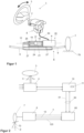
- FIG. 3 shows the steering gear 61 according to the invention.
- An electric motor 14 with a control unit (power pack) has a motor shaft 15 which is connected in a rotationally fixed manner to a threaded spindle 16 (drive spindle) of a ball screw 17.
- the connection can be made directly or via a coupling. It is preferably designed to be flush. It can also be provided that the motor drives the threaded spindle via a reduction gear.
- the threaded spindle 16 is rotatably mounted about a longitudinal axis 160 at both ends in ball bearings 18, in particular spindle bearings, in a housing 19. It is preferably provided that the ball bearings 18 are designed as fixed bearings on one side and as floating bearings on the other side.
- the ball screw 17 has a ball nut 20 which sits on the threaded spindle 16 and surrounds it concentrically.
- the ball nut 20 is held on its outside in a linear guide 21.
- the linear guide 21 is attached to the inside of the housing 19 or is formed integrally with the housing 19.
- the linear guide 21 provides a translational movement of the ball nut 20 along the longitudinal axis 160 This support converts a rotary motion of the threaded spindle 16 into a linear motion of the ball nut 20 along the longitudinal axis 160.
- the linear guide 21 can absorb radial and/or tilting loads.
- the ball nut 20 is connected to the tie rods 9 directly or by means of additional components. A steering motion is thus generated by moving the ball nut 20 along the longitudinal axis 160.
- a non-central arrangement of the actuator 6 in relation to the wheels can be compensated by the geometry of the connecting elements.
- the nut 20 of the spindle drive 17 is connected via a lever 22 to a joint 23 of a first tie rod 9 and moves this in the axial direction.
- the joint 23 is preferably an inner joint that is arranged at the end of the tie rod 9 remote from the wheel.
- the movement of this tie rod is transmitted to the other side, to the second tie rod 9, by means of a coupling rod 24, to which the inner joints 23 of both tie rods 9 are connected.
- the coupling rod 24 is guided linearly in a simple second housing 25 and absorbs the radial components of the tie rod forces.
- the spindle drive 17 and the electric motor 14 or the power pack are located in the area of the coupling rod 24 and are aligned parallel to it.
- the lever 22 is designed such that the spindle drive 17 and the power pack are in the immediate vicinity of the coupling rod 24, which makes the arrangement particularly compact.
- the lever 22 is preferably rigid in the longitudinal direction. In its simplest embodiment, it is straight and has no angles.
- the lever 22 is preferably designed such that it connects the coupling rod 24, which are parallel to one another, and the threaded spindle 16 over the shortest distance.
- the spindle drive 17 or the housing 19 can be sealed to the outside with a bellows 26, which is attached to the motor housing, for example. A seal with a bellows 26 is shown, which extends from the housing 19 to the lever 22.
- the housing 25 in which the coupling rod 24 is arranged is also preferably sealed to the outside at both ends with a bellows 27.
- the two bellows 27 each extend from the housing 25 to the internal thread 23 of the corresponding tie rod 9.
- the ball screw 17 Since radial and tilting loads are absorbed by the linear guide 21, the ball screw 17 is almost exclusively axially loaded and can be made much smaller, lighter and more cost-effective than conventional designs. With the same load capacity, the friction behavior is significantly improved.
- the spindle length corresponds to the stroke of the gear 17, plus surcharges for thread runout and bearing.
- the bearing of the nut 20 is omitted, which is an advantage in terms of installation space requirements in the radial direction, which is often very limited. Due to the more favorable dimensioning of the ball screw 17, the transmission ratio of upstream transmission stages (such as a belt drive) can be reduced, or they can even be dispensed with entirely, which offers advantages in terms of costs and - crucial for the steer-by-wire system - functional safety. Another advantage is the lower rotational imbalance compared to solutions in which the nut rotates.
- the invention is not limited to ball screws; screw drives in general, including roller screws or trapezoidal screws, can be used.
Landscapes
- Engineering & Computer Science (AREA)
- Chemical & Material Sciences (AREA)
- Combustion & Propulsion (AREA)
- Transportation (AREA)
- Mechanical Engineering (AREA)
- Power Steering Mechanism (AREA)
- Steering Control In Accordance With Driving Conditions (AREA)
Description
- Die vorliegende Erfindung betrifft ein Lenkgetriebe für ein Steer-by-Wire-Lenksystem eines Kraftfahrzeuges mit den Merkmalen des Oberbegriffs des Anspruchs 1 und ein Steer-by-Wire-Lenksystem mit den Merkmalen des Oberbegriffs des Anspruchs 7.
- Bei Steer-by-Wire-Lenksystemen ist die Stellung der gelenkten Räder nicht direkt mit dem Lenkeingabemittel, beispielsweise einem Lenkrad, gekoppelt. Es besteht eine Verbindung zwischen dem Lenkrad und den gelenkten Rädern über elektrische Signale. Der Fahrerlenkwunsch wird von einem Lenkwinkelsensor abgegriffen, und in Abhängigkeit von dem Fahrerlenkwunsch wird über einen Lenksteller die Stellung der gelenkten Räder geregelt. Es ist bekannt zwei Lenkaktuatoren vorzusehen, die jeweils einem der lenkbaren Räder zugeordnet sind und zum Einstellen eines Lenkwinkels des jeweiligen Rads eingerichtet sind. Es kann auch ein Zahnstangen-Lenkgetriebe vorgesehen sein, das in Eingriff mit einem Ritzel steht, welches von einem Lenkaktuator angetrieben wird.
- In elektromechanischen Lenkgetrieben ist es bekannt, achsparallele Kugelgewindetriebe zur Umwandlung eines Motordrehmoments eines Hilfsantriebs in eine lineare Bewegung der Zahnstange einzusetzen. Die Anbindung der Zahnstange an das Lenkritzel lässt axiale Bewegungen der Zahnstange zu, während Rotationen der Zahnstange behindert sind. Der Kugelgewindetrieb ist somit mit angetriebener und drehbar gelagerter Kugelmutter ausgeführt. Aus der Offenlegungsschrift
DE 10 2012 015 181 A1 ist eine elektromechanische Kraftfahrzeuglenkung bekannt, die parallel zur Zahnstange einen Hilfsantrieb mit einer Spindel und einer darauf angeordneten Kugelmutter aufweist. Die Zahnstange und die Spindel sind an ihren Enden über eine Stirnplatte miteinander verbunden, sodass eine Verlagerung gegeneinander in Axialrichtung nicht möglich ist. Eine Verbindung zu den Spurstangen kann im Bereich der Enden realisiert werden. - Solche Kugelgewindetriebe (bzw. Rollengewinde- oder Trapezspindeltriebe) nehmen nicht nur Axialkräfte, sondern auch Radialkräfte und Kippmomente, die über die Spurstangen eingeleitet werden, auf. Dadurch ergibt sich eine ungünstige Belastung des Gewindetriebs und damit eine wesentlich größere Dimensionierung als bei hauptsächlich axialer Belastung. Trotz konstruktiver Maßnahmen zur Reduktion der Verkippungsempfindlichkeit (bspw. durch nachgiebige Anbindung des Kugelgewindetriebs mittels Wellfedern) verschlechtert sich das Reibverhalten des Lenkgetriebes aufgrund dieser Belastungskomponenten deutlich.
- Aus der
US 2008/0011537 A1 ist zudem ein elektromechanisches Lenksystem, das auch als Steer-by-Wire-Lenksystem ausgebildet sein kann, bekannt, bei dem ein Elektromotor zur Bereitstellung einer Lenkunterstützung über eine Kugelgewindespindel auf die Zahnstange des Lenksystems wirkt. - Weitere elektromechanische Lenksysteme, bei denen von einem Elektromotor über einen Gewindetrieb eine Lenkunterstützung auf die Zahnstange des Lenksystems aufgebracht wird, sind aus der
US 2007/0089926 A1 und derUS 4,742,882 A bekannt. - Das Dokument
US4653602 offenbart ein Lenkgetriebe gemäß dem Oberbegriff des Anspruchs 1. - Es ist Aufgabe der vorliegenden Erfindung, ein Lenkgetriebe für ein Steer-by-Wire-Lenksystem eines Kraftfahrzeuges anzugeben, das einen geringen Bauraumbedarf aufweist und ein besseres Reibverhalten des Lenkgetriebes ermöglicht.
- Diese Aufgabe wird von einem Lenkgetriebe für ein Steer-by-Wire-Lenksystem eines Kraftfahrzeuges mit den Merkmalen des Anspruchs 1 und einem Steer-by-Wire-Lenksystem eines Kraftfahrzeuges mit den Merkmalen des Anspruchs 7 gelöst.
- Demnach ist ein Lenkgetriebe für ein Steer-by-Wire-Lenksystem eines Kraftfahrzeuges mit einem Elektromotor aufweisend eine Motorwelle vorgesehen, wobei die Motorwelle eine Spindel eines Schraubgetriebes antreibt, und das Schraubgetriebe eine Spindelmutter umfasst, derart, dass eine von der Motorwelle ausgehende Drehbewegung in eine Linearbewegung der Spindelmutter entlang einer Achse umgesetzt wird, wobei die Spindelmutter zur Lenkung von Rädern des Kraftfahrzeuges mit wenigstens einer Spurstange verbunden ist. Im Gegensatz zu elektromechanischen Lenkungen entfällt in Steer-by-Wire-Systemen die Anbindung des Lenkritzels. Der Antrieb erfolgt erfindungsgemäß über eine drehbar gelagerte Spindel, wodurch Bauraum eingespart wird. Vorzugsweise ist das Schraubgetriebe ein Kugelgewindetrieb, ein Trapezgewindetrieb oder ein Rollengewindetrieb. Es ist bevorzugt vorgesehen, dass das Schraubgetriebe in einem Gehäuse angeordnet ist, in dem die Spindel drehbar und die Spindelmutter mit einer axialen Führung gelagert sind.
- Es ist denkbar und möglich, dass an der Spindel oder der Motorwelle ein Drehwinkelsensor vorgesehen ist, sodass dadurch die Verdrehung der Motorwelle oder der Spindel ein Drehwinkel gemessen werden kann.
- Es ist weiterhin denkbar und möglich, dass ein Linearpositionssensor vorgesehen ist, welcher an der Spindelmutter oder an einem anderen axial beweglichen Bauteil des Lenkgetriebes angeordnet ist und dessen Verschiebung erfasst.
- Die direkte Anbindung der Spindelmutter erfolgt bevorzugt an eine einzige Spurstange, insbesondere über einen in Axialrichtung starren Hebel, so dass die Linearbewegung der Spindelmutter auf diese Spurstange übertragen wird.
- Vorzugsweise ist der Hebel derart ausgestaltet, dass die Achse der Linearbewegung sich parallel zur Bewegungsrichtung der Spurstange (bzw. des Anlenkpunktes der Spurstange) erstreckt. Der Hebel ist vorzugsweise gerade und weist keine Winkel auf.
- Es ist bevorzugt, wenn der Hebel mit einem Innengewinde der Spurstange verbunden ist. Weiterhin kann der Hebel mit einem Gelenk mit der Spurstange verbunden werden und dieses in axialer Richtung bewegen. Das Gelenk ist bevorzugt ein Innengelenk.
- Weiterhin ist ein Steer-by-Wire-Lenksystem für ein Kraftfahrzeug vorgesehen, umfassend:
- einen auf die gelenkten Räder wirkenden elektronisch regelbaren Lenksteller,
- eine Ansteuereinheit,
- einen Feedback-Aktuator, der über ein Lenkeingabemittel von einem Fahrer mit einem Fahrerwunsch für einen Lenkwinkel beaufschlagt werden kann und ein Feedback-Signal an das Lenkeingabemittel als Reaktion auf den Fahrerwunsch und einen Fahrzustand des Kraftfahrzeugs ausgibt,
- eine Einrichtung zur Signalübertragung, die den Fahrerwunsch an die Ansteuereinheit übermittelt,
- In einer vorteilhaften Ausführungsform des Lenksystems wird die Bewegung der mit der Spindelmutter unmittelbar verbundenen Spurstange mittels einer sich parallel zur Bewegungsrichtung der Spindelmutter erstreckenden Koppelstange auf eine zweite Spurstange des Lenksystems übertragen.
- Vorzugsweise ist der Elektromotor im Bereich der Koppelstange angeordnet. Der Spindeltrieb und der Elektromotor mit der Ansteuereinheit sind bevorzugt parallel zu der Koppelstange ausgerichtet, was durch den Hebel ermöglicht wird. Dabei handelt es sich um eine besonders platzsparende Ausführungsform. Der Elektromotor weist eine Motorwelle auf, die mit einer Gewindespindel des Schraubgetriebes drehfest verbunden ist. Die Verbindung kann vorzugsweise unmittelbar oder über eine Kupplung erfolgen. Sie ist bevorzugt fluchtend ausgebildet. Es kann auch vorgesehen sein, dass der Motor die Gewindespindel über ein Untersetzungsgetriebe antreibt.
- Es ist von Vorteil, wenn das Schraubgetriebe oder das Gehäuse des Schraubgetriebes mit einem Faltenbalg nach außen hin abgedichtet ist.
- Vorzugsweise ist die Koppelstange in einem Gehäuse angeordnet, das nach außen hin mit wenigstens einem Faltenbalg abgedichtet ist.
- Eine bevorzugte Ausführungsform der Erfindung wird nachfolgend anhand der Zeichnungen näher erläutert. Gleichartige oder gleichwirkende Bauteile werden in den Figuren mit denselben Bezugszeichen bezeichnet. Es zeigen:
- Fig. 1:
- eine schematische Darstellung eines Steer-by-Wire-Lenksystems,
- Fig. 2:
- ein Blockdiagramm einer Steuerung des Steer-by-Wire-Lenksystems, sowie
- Fig. 3:
- eine schematische Darstellung eines Lenkgetriebes.
- In der
Figur 1 ist ein Steer-by-Wire-Lenksystem 1 gezeigt. An einer Lenkwelle 2 ist ein nicht dargestellter Drehwinkelsensor angebracht, welcher den durch Drehen eines Lenkeingabemittels 3, welches im Beispiel als Lenkrad ausgebildet ist, aufgebrachten Fahrerlenkwinkel erfasst. Es kann aber zusätzlich auch ein Lenkmoment erfasst werden. Als Lenkeingabemittel kann ein Joy-Stick dienen. Des Weiteren ist an der Lenkwelle 2 ein Feedback-Aktuator 4 angebracht, welcher dazu dient, die Rückwirkungen von der Fahrbahn 70 auf das Lenkrad 3 zu simulieren und somit dem Fahrer eine Rückmeldung über das Lenk- und Fahrverhalten des Fahrzeugs zu geben. Der Fahrerlenkwunsch wird über den vom Drehwinkelsensor gemessenen Drehwinkel α der Lenkwelle 2 über Signalleitungen an eine Feedback-Aktuator-Monitoreinheit 10 übertragen, wie dies in derFigur 2 veranschaulicht ist. Die Feedback-Aktuator-Monitoreinheit 10 überträgt den Fahrerlenkwunsch an die Ansteuereinheit 60. Die Feedback-Aktuator-Monitoreinheit 10 übernimmt bevorzugt auch die Ansteuerung des Feedback-Aktuators 4. Die Feedback-Aktuator-Monitoreinheit 10 kann auch integral mit der Ansteuereinheit 60 ausgebildet sein. Die Ansteuereinheit 60 steuert in Abhängigkeit von dem Signal des Drehwinkelsensors sowie weiteren Eingangsgrößen einen elektrischen Lenkaktuator 6 an, welcher die Stellung der gelenkten Räder 7 steuert. Der Lenkaktuator 6 wirkt über ein Lenkstangen-Lenkgetriebe 8, wie beispielsweise einem Zahnstangen-Lenkgetriebe, sowie über Spurstangen 9 und anderen Bauteilen mittelbar auf die gelenkten Räder 7. Die detaillierte Beschreibung des erfindungsgemäßen Lenkgetriebes 61 erfolgt unterFigur 3 . -
Figur 2 zeigt eine Steuerung eines Lenkaktuators 6. Der Lenkaktuator 6 empfängt den Lenkwinkel α von der Ansteuereinheit 60. Die an einer Zahnstange 12 gemessene Zahnstangenposition 120 und weitere Fahrbahninformationen 13 werden an die Ansteuereinheit 60 weiter gegeben. Die Ansteuerungseinheit 60 bestimmt die Zahnstangenkraft mittels bekannter Mess- oder Schätzverfahren und berechnet daraus ein Lenkmoment T,fb. Der Feedback-Aktuator 4 wird entsprechend angesteuert, wodurch ein Lenkgefühl erzeugt wird. Die Ansteuerungseinheit 60 empfängt weiterhin fahrerseitige Lenkbefehle 51, wie den Lenkwinkelstatus. Der Feedback-Aktuator 4 empfängt Signale über die Signalleitung 50 unter anderem von dem Drehwinkelsensor, der den Lenkwinkel α, die Lenkwinkelbeschleunigung und die Lenkwinkelgeschwindigkeit misst und speichert. Der Feedback-Aktuator 4 kommuniziert mit einer Feedback-Aktuator-Monitoreinheit 10, die den Feedback-Aktuator 4 steuert. Die Feedback-Aktuator-Monitoreinheit 10 empfängt von der Ansteuereinheit 60 des Lenkaktuators 6 den Ist-Radlenkwinkel β der gelenkten Räder 7, sowie weitere Größen, die die Ansteuereinheit 60 ermittelt hat. -
Figur 3 zeigt das erfindungsgemäße Lenkgetriebe 61. Ein Elektromotor 14 mit Steuereinheit (Power Pack) weist eine Motorwelle 15 auf, die mit einer Gewindespindel 16 (Antriebsspindel) eines Kugelgewindetriebs 17 drehfest verbunden ist. Die Verbindung kann unmittelbar oder über eine Kupplung erfolgen. Sie ist bevorzugt fluchtend ausgebildet. Es kann auch vorgesehen sein, dass der Motor die Gewindespindel über ein Untersetzungsgetriebe antreibt. Die Gewindespindel 16 ist drehbar um eine Längsachse 160 an ihren beiden Enden in Kugellagern 18, insbesondere Spindellagern, in einem Gehäuse 19 gelagert. Es ist bevorzugt vorgesehen, dass die Kugellager 18 auf der einen Seite als Festlager und auf der anderen Seite als Loslager ausgebildet sind. Der Kugelgewindetrieb 17 weist eine Kugelmutter 20 auf, die auf der Gewindespindel 16 sitzt und diese konzentrisch umgibt. Die Kugelmutter 20 wird auf ihrer Außenseite in einer Linearführung 21 gehalten. Die Linearführung 21 ist an der Innenseite des Gehäuses 19 befestigt oder einstückig mit dem Gehäuse 19 ausgebildet. Die Linearführung 21 gibt eine translatorische Bewegung der Kugelmutter 20 entlang der Längsachse 160 vor. Durch diese Abstützung erfolgt eine Umsetzung einer Drehbewegung der Gewindespindel 16 in eine Linearbewegung der Kugelmutter 20 entlang der Längsachse 160. Die Linearführung 21 kann Radial- und/oder Kippbelastungen aufnehmen. Die Kugelmutter 20 ist direkt oder mittels zusätzlicher Bauteile mit den Spurstangen 9 verbunden. Durch Bewegung der Kugelmutter 20 entlang der Längsachse 160 wird somit eine Lenkbewegung erzeugt. Eine in Bezug auf die Räder nicht mittige Anordnung des Aktuators 6 kann durch die Geometrie der Anschlusselemente kompensiert werden. - In der in
Figur 3 gezeigten Ausführungsform ist die Mutter 20 des Spindeltriebs 17 über einen Hebel 22 mit einem Gelenk 23 einer ersten Spurstange 9 verbunden und bewegt dieses in axialer Richtung. Das Gelenk 23 ist bevorzugt ein Innengelenk, das an dem radfernen Ende der Spurstange 9 angeordnet ist. Die Bewegung dieser Spurstange wird mittels einer Koppelstange 24, mit der die Innengelenke 23 beider Spurstangen 9 verbunden sind, auf die andere Seite, auf die zweite Spurstange 9, übertragen. Die Koppelstange 24 ist in einem einfachen zweiten Gehäuse 25 linear geführt und nimmt die radialen Anteile der Spurstangenkräfte auf. Der Spindeltrieb 17 und der Elektromotor 14 bzw. das Powerpack liegen im Bereich der Koppelstange 24 und sind parallel zu dieser ausgerichtet. Der Hebel 22 ist so ausgestaltet, dass der Spindeltrieb 17 und das Powerpack in unmittelbarer Nähe zu der Koppelstange 24 liegen, was die Anordnung besonders kompakt macht. Der Hebel 22 ist bevorzugt in Längsrichtung starr. In seiner einfachsten Ausführungsform ist er gerade und weist keine Winkel auf. Der Hebel 22 ist vorzugsweise so ausgestaltet, dass er die parallel zueinander liegende Koppelstange 24 und die Gewindespindel 16 über den kürzesten Abstand verbindet. Der Spindelantrieb 17 bzw. das Gehäuse 19 kann mit einem Faltenbalg 26 nach außen abgedichtet werden, der beispielsweise am Motorgehäuse befestigt ist. Dargestellt ist eine Abdichtung mit einem Faltenbalg 26, der sich ausgehend von dem Gehäuse 19 zum Hebel 22 hin erstreckt. Das Gehäuse 25 in dem die Koppelstange 24 angeordnet ist, wird ebenfalls bevorzugt nach außen hin an beiden Ende mit einem Faltenbalg 27 abgedichtet. Die beiden Faltenbälge 27 erstrecken sich dabei jeweils von dem Gehäuse 25 zum Innengewinde 23 der entsprechenden Spurstange 9 hin. - Da Radial- und Kippbelastungen von der Linearführung 21 aufgenommen werden, ist der Kugelgewindetrieb 17 fast ausschließlich axial belastet und kann wesentlich kleiner, leichter und kostengünstiger ausgeführt werden als bei herkömmlichen Konstruktionen. Bei gleicher Belastbarkeit ergibt sich ein deutlich verbessertes Reibverhalten. Die Spindellänge entspricht dem Hub des Getriebes 17, zzgl. Aufschlägen für Gewindeauslauf und Lagerung. Die Lagerung der Mutter 20 entfällt, was einen Vorteil hinsichtlich Bauraumbedarf in der in vielen Fällen stark begrenzten radialen Richtung bedeutet. Durch die günstigere Dimensionierung des Kugelgewindetriebs 17 kann das Übersetzungsverhältnis vorgelagerter Übersetzungsstufen (wie beispielsweise eines Riementriebs) reduziert werden, oder es kann sogar ganz auf diese verzichtet werden, was Vorteile hinsichtlich Kosten und - entscheidend für das Steer-by-Wire-System - funktionaler Sicherheit bietet. Ein weiterer Vorteil besteht in der geringeren Drehunwucht im Vergleich mit Lösungen, bei denen sich die Mutter dreht.
- Die Erfindung beschränkt sich nicht auf Kugelgewindetriebe, es können allgemein Schraubgetriebe, also auch Rollengewindetriebe oder Trapezgewindetriebe zum Einsatz kommen.
Claims (10)
- Lenkgetriebe (61) für ein Steer-by-Wire-Lenksystem (1) eines Kraftfahrzeuges mit einem Elektromotor (14) aufweisend eine Motorwelle (15), wobei die Motorwelle (15) eine Spindel (16) eines Schraubgetriebes (17) antreibt, und das Schraubgetriebe (17) eine Spindelmutter (20) umfasst, derart, dass eine von der Motorwelle (15) ausgehende Drehbewegung in eine Linearbewegung der Spindelmutter (20) entlang einer Achse (160) umgesetzt wird, dadurch gekennzeichnet, dass die Spindelmutter (20) über einen Hebel (22) zur Lenkung von Rädern des Kraftfahrzeuges mit einem Gelenk (23) einer ersten Spurstange (9) verbunden ist, und dass das Lenkgetriebe (61) eine sich parallel zur Bewegungsrichtung der Spindelmutter (20) erstreckende Koppelstange (24) umfasst, die die Bewegung der mit der Spindelmutter (20) unmittelbar verbundenen Spurstange (9) auf eine zweite Spurstange (9) überträgt.
- Lenkgetriebe nach Anspruch 1, dadurch gekennzeichnet, dass das Schraubgetriebe (17) ein Kugelgewindetrieb, ein Trapezgewindetrieb oder ein Rollengewindetrieb ist.
- Lenkgetriebe nach Anspruch 1 oder 2, dadurch gekennzeichnet, dass das Schraubgetriebe (17) in einem Gehäuse (19) angeordnet ist, in dem die Spindel (16) drehbar und die Spindelmutter (20) mit einer axialen Führung gelagert sind.
- Lenkgetriebe nach einem der vorhergehenden Ansprüche, dadurch gekennzeichnet, dass die Spindelmutter (20) über einen in Axialrichtung starren Hebel (22) als den Hebel (22) mit einer einzigen Spurstange (9) unmittelbar verbunden ist, so dass die Linearbewegung der Spindelmutter (20) auf diese Spurstange (9) übertragen wird.
- Lenkgetriebe nach Anspruch 4, dadurch gekennzeichnet, dass der Hebel (22) derart ausgestaltet ist, dass die Achse der Linearbewegung (160) sich parallel zur Bewegungsrichtung der Spurstange (9) erstreckt.
- Lenkgetriebe nach Anspruch 4 oder 5, dadurch gekennzeichnet, dass der Hebel (22) mit einem Innengewinde (23) der Spurstange (9) verbunden ist.
- Steer-by-Wire-Lenksystem (1) für ein Kraftfahrzeug umfassend:- einen auf die gelenkten Räder (7) wirkenden elektronisch regelbaren Lenkaktuator (6),- eine Ansteuereinheit (60),- einen Feedback-Aktuator (4), der über ein Lenkeingabemittel (3) von einem Fahrer mit einem Fahrerwunsch für einen Lenkwinkel beaufschlagt werden kann und ein Feedback-Signal an das Lenkeingabemittel (3) als Reaktion auf den Fahrerwunsch und einen Fahrzustand des Kraftfahrzeugs ausgibt,- eine Einrichtung zur Signalübertragung, die den Fahrerwunsch an die Ansteuereinheit (60) übermittelt,wobei die Ansteuereinheit (60) den Lenkaktuator ansteuert, um den Fahrerwunsch in eine Auslenkung der gelenkten Räder (7) zu transformieren, dadurch gekennzeichnet, dass der Lenkaktuator (6) Teil eines nach einem der vorhergehenden Ansprüche 1 bis 6 ausgebildeten Lenkgetriebes (61) ist.
- Steer-by-Wire-Lenksystem nach Anspruch 7, dadurch gekennzeichnet, dass der Elektromotor (14) im Bereich der Koppelstange (24) angeordnet ist.
- Steer-by-Wire-Lenksystem nach einem der vorhergehenden Ansprüche 7 oder 8, dadurch gekennzeichnet, dass das Schraubgetriebe (17) oder das Gehäuse (19) des Schraubgetriebes mit einem Faltenbalg (26) nach außen hin abgedichtet ist.
- Steer-by-Wire-Lenksystem nach einem der vorhergehenden Ansprüche 7 bis 9, dadurch gekennzeichnet, dass die Koppelstange (24) in einem Gehäuse (25) angeordnet ist, das nach außen hin mit wenigstens einem Faltenbalg (27) abgedichtet ist.
Applications Claiming Priority (2)
| Application Number | Priority Date | Filing Date | Title |
|---|---|---|---|
| DE102018119977.5A DE102018119977A1 (de) | 2018-08-16 | 2018-08-16 | Lenkgetriebe für ein Steer-by-Wire-Lenksystem |
| PCT/EP2019/071424 WO2020035409A1 (de) | 2018-08-16 | 2019-08-09 | Lenkgetriebe für ein steer-by-wire-lenksystem |
Publications (2)
| Publication Number | Publication Date |
|---|---|
| EP3837151A1 EP3837151A1 (de) | 2021-06-23 |
| EP3837151B1 true EP3837151B1 (de) | 2025-01-15 |
Family
ID=67587778
Family Applications (1)
| Application Number | Title | Priority Date | Filing Date |
|---|---|---|---|
| EP19752496.0A Active EP3837151B1 (de) | 2018-08-16 | 2019-08-09 | Lenkgetriebe für ein steer-by-wire-lenksystem |
Country Status (5)
| Country | Link |
|---|---|
| US (1) | US12060114B2 (de) |
| EP (1) | EP3837151B1 (de) |
| CN (1) | CN112566834B (de) |
| DE (1) | DE102018119977A1 (de) |
| WO (1) | WO2020035409A1 (de) |
Families Citing this family (5)
| Publication number | Priority date | Publication date | Assignee | Title |
|---|---|---|---|---|
| US10814904B2 (en) * | 2018-05-21 | 2020-10-27 | Ford Global Technologies, Llc | Steering actuators for vehicles |
| DE102018123424A1 (de) | 2018-09-24 | 2020-03-26 | Thyssenkrupp Ag | Steer-by-Wire-Lenkgetriebe mit Druckstück gelagerter Koppelstange |
| US11866106B2 (en) | 2021-03-19 | 2024-01-09 | Ford Global Technologies, Llc | Methods and apparatus to determine loads encountered by a steering rack |
| DE102021128531A1 (de) | 2021-11-03 | 2023-05-04 | Bayerische Motoren Werke Aktiengesellschaft | Lenkung für einen Kraftwagen, insbesondere einen Personenkraftwagen, sowie Kraftwagen |
| DE102023121376B4 (de) * | 2023-08-10 | 2025-07-03 | Schaeffler Technologies AG & Co. KG | Verbinder, Linearantrieb, Lenksystem sowie Fahrzeug |
Citations (1)
| Publication number | Priority date | Publication date | Assignee | Title |
|---|---|---|---|---|
| US4653602A (en) * | 1985-10-17 | 1987-03-31 | General Motors Corporation | Electric motor driven rack and pinion steering gear with take-off from axially slidable nut |
Family Cites Families (42)
| Publication number | Priority date | Publication date | Assignee | Title |
|---|---|---|---|---|
| DE800480C (de) | 1948-10-02 | 1950-11-09 | Ind Werke Karlsruhe A G | Walzvorrichtung zur Herstellung von ringfoermig verlaufenden Rillen auf duennwandigen Rohren |
| US3508633A (en) | 1967-05-17 | 1970-04-28 | Nissan Motor | Plastically deformable impact absorbing means for vehicles |
| US3699624A (en) | 1969-05-14 | 1972-10-24 | Koppy Corp | Stretch method for making a tubular product |
| GB1262913A (en) | 1969-08-11 | 1972-02-09 | Standard Telephones Cables Ltd | Method of forming a transversely corrugated tube |
| DE2459246A1 (de) | 1974-12-14 | 1976-06-16 | Reiche & Co | Aussenmantelrohr fuer eine kraftfahrzeug-lenkspindel oder rohrfoermige kraftfahrzeug-lenkspindel |
| DE2505340B1 (de) | 1975-02-08 | 1976-07-08 | Daimler Benz Ag | Sicherheitslenksaeule fuer personenkraftwagen |
| JPH06503B2 (ja) | 1985-12-09 | 1994-01-05 | 株式会社ユニシアジェックス | 電動式パワ−ステアリング装置 |
| US4742882A (en) * | 1986-03-12 | 1988-05-10 | Honda Giken Kogyo Kabushiki Kaisha | Motor-driven power steering device |
| JPH05270415A (ja) | 1992-03-30 | 1993-10-19 | Aisin Seiki Co Ltd | 車輌の副操舵機構付ステアリング装置 |
| JP3341411B2 (ja) | 1993-11-26 | 2002-11-05 | 日本精工株式会社 | 金属製ベローズの製造方法 |
| JP3028905B2 (ja) * | 1994-01-31 | 2000-04-04 | アイシン精機株式会社 | 後輪操舵アクチュエ−タ |
| JP3094053B2 (ja) | 1994-02-25 | 2000-10-03 | 富士機工株式会社 | 車両用ステアリング装置 |
| CN2278793Y (zh) | 1996-10-25 | 1998-04-15 | 杨爱华 | 一种辊式滚动丝杠 |
| US5975234A (en) | 1997-12-03 | 1999-11-02 | Trw Inc. | Electric steering system with plastic motor tube |
| SE517177C2 (sv) | 2000-03-09 | 2002-04-23 | Volvo Lastvagnar Ab | Axelkoppling |
| DE10157797A1 (de) | 2000-11-29 | 2002-09-19 | Continental Teves Ag & Co Ohg | Simulatoreinheit für ein Lenkrad einer Fahrzeuglenkung |
| DE10114308A1 (de) | 2001-03-23 | 2001-08-16 | Zf Lenksysteme Gmbh | Zahnstangen-Hilfskraftlenkung |
| US7591342B2 (en) * | 2001-08-01 | 2009-09-22 | Delphi Technologies, Inc. | Apparatus and method for steering a vehicle |
| US6547029B2 (en) * | 2001-09-10 | 2003-04-15 | Trw Inc. | Vehicle steering apparatus |
| US6691819B2 (en) | 2001-09-17 | 2004-02-17 | Delphi Technologies, Inc. | Actuator for active front wheel steering system |
| JP2003118597A (ja) | 2001-10-10 | 2003-04-23 | Toyota Motor Corp | 車両用操舵装置 |
| DE10200097A1 (de) | 2002-01-03 | 2003-07-17 | Zf Lenksysteme Gmbh | Lenksystem für Kraftfahrzeuge |
| DE10331597A1 (de) | 2003-07-11 | 2005-02-03 | Zf Lenksysteme Gmbh | Aktuator, insbesondere Radaktuator mit einem Abtrieb |
| JP4516479B2 (ja) | 2005-05-24 | 2010-08-04 | 株式会社日立製作所 | 回転直動変換機構 |
| KR100651141B1 (ko) * | 2005-10-24 | 2006-11-29 | 주식회사 만도 | 자동차의 전기식 동력 보조 조향 장치 |
| DE102006008911A1 (de) | 2006-02-27 | 2007-08-30 | Zf Lenksysteme Gmbh | Lenkung mit Hohlwellen-Elektromotor und Zwischengetriebe |
| DE102006048614A1 (de) | 2006-10-13 | 2008-04-17 | Magna Powertrain Ag & Co Kg | Hinterradlenkungs-Aktuator |
| JP2009006955A (ja) | 2007-06-29 | 2009-01-15 | Jtekt Corp | 衝撃吸収式車両用操舵装置 |
| DE102008059745A1 (de) | 2008-12-01 | 2010-06-02 | Thyssenkrupp Presta Ag | Elektromechanische Servolenkung mit Kugelgewindetrieb |
| DE102008063712A1 (de) | 2008-12-19 | 2010-06-24 | Thyssenkrupp Presta Ag | Lenksystem mit geräuschdämmenden Komponenten aus Verbundwerkstoff |
| DE102009024847B4 (de) | 2009-06-09 | 2012-01-26 | Brugg Rohr Ag, Holding | Vorrichtung zur Herstellung wendelförmiger Wellrohre |
| DE102009045857A1 (de) * | 2009-10-20 | 2011-04-21 | Robert Bosch Gmbh | Verfahren zur Herstellung einer Spindel für einen Spindeltrieb, Wälzgewindetrieb mit einer solchen Spindel und Verwendung des Wälzgewindetriebs |
| DE102012015181A1 (de) | 2012-08-02 | 2014-05-15 | Thyssenkrupp Presta Aktiengesellschaft | Lenkgetriebe für ein Kraftfahrzeug |
| DE102013000892A1 (de) | 2013-01-18 | 2014-07-24 | Volkswagen Aktiengesellschaft | Lenkvorrichtung mit Kugelgewindetrieb, Motor und Umlaufrädergetriebe |
| EP3204677B1 (de) | 2014-10-10 | 2019-03-06 | OneSubsea IP UK Limited | Aktuator zur betätigung einer ventilvorrichtung |
| DE102015118292B4 (de) | 2015-10-27 | 2025-01-23 | Knorr-Bremse Systeme für Nutzfahrzeuge GmbH | Lenkgetriebe für ein Fahrzeug, Fahrzeug, Verfahren zum Ansteuern eines Lenkgetriebes und Verfahren zum Lenken eines Fahrzeugs |
| DE102015015148A1 (de) | 2015-11-25 | 2017-06-01 | Thyssenkrupp Ag | Feedback-Aktuator für eine Lenkeinrichtung |
| US10988172B2 (en) | 2016-04-21 | 2021-04-27 | Zf Active Safety And Electronics Us Llc | External damping of power steering for a vehicle |
| DE102016007540A1 (de) | 2016-06-22 | 2017-12-28 | Thyssenkrupp Ag | Kugelgewindetrieb einer elektromechanischen Servolenkung mit integriertem Schrägkugellager und Kompensation unterschiedlicher Wärmeausdehnungen |
| DE102016212812A1 (de) | 2016-07-13 | 2018-01-18 | Volkswagen Aktiengesellschaft | Lenkung für ein Kraftfahrzeug, insbesondere für ein Nutzfahrzeug, mit Lenkwelle und Kugelgewindemutter |
| CN207345912U (zh) | 2017-11-03 | 2018-05-11 | 许昌学院 | 一种新型安全转向柱 |
| CN207565676U (zh) | 2017-12-11 | 2018-07-03 | 浙江梵隆汽车部件有限公司 | 一种方向盘可调式减震装置 |
-
2018
- 2018-08-16 DE DE102018119977.5A patent/DE102018119977A1/de active Pending
-
2019
- 2019-08-09 EP EP19752496.0A patent/EP3837151B1/de active Active
- 2019-08-09 US US17/265,685 patent/US12060114B2/en active Active
- 2019-08-09 CN CN201980053330.8A patent/CN112566834B/zh active Active
- 2019-08-09 WO PCT/EP2019/071424 patent/WO2020035409A1/de not_active Ceased
Patent Citations (1)
| Publication number | Priority date | Publication date | Assignee | Title |
|---|---|---|---|---|
| US4653602A (en) * | 1985-10-17 | 1987-03-31 | General Motors Corporation | Electric motor driven rack and pinion steering gear with take-off from axially slidable nut |
Also Published As
| Publication number | Publication date |
|---|---|
| WO2020035409A1 (de) | 2020-02-20 |
| US12060114B2 (en) | 2024-08-13 |
| CN112566834B (zh) | 2023-07-07 |
| EP3837151A1 (de) | 2021-06-23 |
| DE102018119977A1 (de) | 2020-02-20 |
| US20210171090A1 (en) | 2021-06-10 |
| CN112566834A (zh) | 2021-03-26 |
Similar Documents
| Publication | Publication Date | Title |
|---|---|---|
| EP3837151B1 (de) | Lenkgetriebe für ein steer-by-wire-lenksystem | |
| EP3743324B1 (de) | Lenksäule für ein kraftfahrzeug | |
| DE102008036730B4 (de) | Aktuatoreinheit für eine Kraftfahrzeug-Steer-by-Wire-Lenkeinrichtung | |
| EP1904358B1 (de) | Lenkeinrichtung für eine überlagerungslenkung | |
| EP3322632B1 (de) | Feedback-aktuator für eine lenkeinrichtung | |
| EP0916568B1 (de) | Aktuator zum Erzeugen eines zusätzlichen Lenkwinkels für Strassenfahrzeuge | |
| EP3500476B1 (de) | Steuerhorn für die lenkung eines kaftfahrzeugs | |
| DE102009055021A1 (de) | Mehrfach verstellbare Lenkbestätigungseinheit für ein Kraftfahrzeug mit einem Träger und einer Lenksäule | |
| WO2020058025A1 (de) | Lenksäule und steer-by-wire lenksystem | |
| EP3148860B1 (de) | Lenkwelle für eine kraftfahrzeuglenkung | |
| DE4243267B4 (de) | Lenkgetriebe | |
| EP3956201A1 (de) | Steer-by-wire lenksystem für ein kraftfahrzeug mit konzentrischem antrieb | |
| EP2117906B1 (de) | Elektromechanische lenkung | |
| DE10234596B3 (de) | Als Kugelumlauflenkung ausgebildete elektrische Servolenkung eines Kraftfahrzeuges | |
| EP1375303B1 (de) | Hydrolenkung für Kraftfahrzeuge | |
| DE10236261A1 (de) | Kraftfahrzeuglenkung mit Überlagerungslenkung | |
| DE102018115937B4 (de) | Lenkradeinheit zur Erfassung einer Lenkbewegung eines Lenkrades für ein elektromechanisches Lenksystem | |
| DE102007015338A1 (de) | Elektromechanische Lenkung | |
| BE1032176B1 (de) | Verfahren zur Messung der auf eine Zahnstange eines Lenkgetriebes eines Lenksystems für ein Kraftfahrzeug wirkenden Zahnstangenkraft und Lenksystem | |
| DE102024003822B4 (de) | Steer-by-Wire-Lenksystem für ein Kraftfahrzeug sowie Kraftfahrzeug | |
| DE102022133455B4 (de) | Lenkeinrichtung für Steer-by-wire-Lenksystem | |
| DE102015224252A1 (de) | Elektromechanische Lenkung mit koaxialem Motor | |
| DE102004020075A1 (de) | Lenkgetriebe einer Überlagerungslenkung | |
| EP1637436A1 (de) | Fahrzeuglenkung | |
| DE10259574A1 (de) | Servolenkung, insbesondere eines Kraftfahrzeuges |
Legal Events
| Date | Code | Title | Description |
|---|---|---|---|
| STAA | Information on the status of an ep patent application or granted ep patent |
Free format text: STATUS: UNKNOWN |
|
| STAA | Information on the status of an ep patent application or granted ep patent |
Free format text: STATUS: THE INTERNATIONAL PUBLICATION HAS BEEN MADE |
|
| PUAI | Public reference made under article 153(3) epc to a published international application that has entered the european phase |
Free format text: ORIGINAL CODE: 0009012 |
|
| STAA | Information on the status of an ep patent application or granted ep patent |
Free format text: STATUS: REQUEST FOR EXAMINATION WAS MADE |
|
| 17P | Request for examination filed |
Effective date: 20210316 |
|
| AK | Designated contracting states |
Kind code of ref document: A1 Designated state(s): AL AT BE BG CH CY CZ DE DK EE ES FI FR GB GR HR HU IE IS IT LI LT LU LV MC MK MT NL NO PL PT RO RS SE SI SK SM TR |
|
| DAV | Request for validation of the european patent (deleted) | ||
| DAX | Request for extension of the european patent (deleted) | ||
| STAA | Information on the status of an ep patent application or granted ep patent |
Free format text: STATUS: EXAMINATION IS IN PROGRESS |
|
| 17Q | First examination report despatched |
Effective date: 20230630 |
|
| GRAP | Despatch of communication of intention to grant a patent |
Free format text: ORIGINAL CODE: EPIDOSNIGR1 |
|
| STAA | Information on the status of an ep patent application or granted ep patent |
Free format text: STATUS: GRANT OF PATENT IS INTENDED |
|
| INTG | Intention to grant announced |
Effective date: 20240911 |
|
| GRAS | Grant fee paid |
Free format text: ORIGINAL CODE: EPIDOSNIGR3 |
|
| GRAA | (expected) grant |
Free format text: ORIGINAL CODE: 0009210 |
|
| STAA | Information on the status of an ep patent application or granted ep patent |
Free format text: STATUS: THE PATENT HAS BEEN GRANTED |
|
| AK | Designated contracting states |
Kind code of ref document: B1 Designated state(s): AL AT BE BG CH CY CZ DE DK EE ES FI FR GB GR HR HU IE IS IT LI LT LU LV MC MK MT NL NO PL PT RO RS SE SI SK SM TR |
|
| REG | Reference to a national code |
Ref country code: CH Ref legal event code: EP Ref country code: GB Ref legal event code: FG4D Free format text: NOT ENGLISH |
|
| REG | Reference to a national code |
Ref country code: DE Ref legal event code: R096 Ref document number: 502019012818 Country of ref document: DE |
|
| REG | Reference to a national code |
Ref country code: IE Ref legal event code: FG4D Free format text: LANGUAGE OF EP DOCUMENT: GERMAN |
|
| REG | Reference to a national code |
Ref country code: DE Ref legal event code: R084 Ref document number: 502019012818 Country of ref document: DE |
|
| REG | Reference to a national code |
Ref country code: NL Ref legal event code: MP Effective date: 20250115 |
|
| PG25 | Lapsed in a contracting state [announced via postgrant information from national office to epo] |
Ref country code: NL Free format text: LAPSE BECAUSE OF FAILURE TO SUBMIT A TRANSLATION OF THE DESCRIPTION OR TO PAY THE FEE WITHIN THE PRESCRIBED TIME-LIMIT Effective date: 20250115 |
|
| PG25 | Lapsed in a contracting state [announced via postgrant information from national office to epo] |
Ref country code: RS Free format text: LAPSE BECAUSE OF FAILURE TO SUBMIT A TRANSLATION OF THE DESCRIPTION OR TO PAY THE FEE WITHIN THE PRESCRIBED TIME-LIMIT Effective date: 20250415 |
|
| PG25 | Lapsed in a contracting state [announced via postgrant information from national office to epo] |
Ref country code: FI Free format text: LAPSE BECAUSE OF FAILURE TO SUBMIT A TRANSLATION OF THE DESCRIPTION OR TO PAY THE FEE WITHIN THE PRESCRIBED TIME-LIMIT Effective date: 20250115 |
|
| PG25 | Lapsed in a contracting state [announced via postgrant information from national office to epo] |
Ref country code: PL Free format text: LAPSE BECAUSE OF FAILURE TO SUBMIT A TRANSLATION OF THE DESCRIPTION OR TO PAY THE FEE WITHIN THE PRESCRIBED TIME-LIMIT Effective date: 20250115 |
|
| PG25 | Lapsed in a contracting state [announced via postgrant information from national office to epo] |
Ref country code: ES Free format text: LAPSE BECAUSE OF FAILURE TO SUBMIT A TRANSLATION OF THE DESCRIPTION OR TO PAY THE FEE WITHIN THE PRESCRIBED TIME-LIMIT Effective date: 20250115 |
|
| REG | Reference to a national code |
Ref country code: LT Ref legal event code: MG9D |
|
| PG25 | Lapsed in a contracting state [announced via postgrant information from national office to epo] |
Ref country code: IS Free format text: LAPSE BECAUSE OF FAILURE TO SUBMIT A TRANSLATION OF THE DESCRIPTION OR TO PAY THE FEE WITHIN THE PRESCRIBED TIME-LIMIT Effective date: 20250515 Ref country code: NO Free format text: LAPSE BECAUSE OF FAILURE TO SUBMIT A TRANSLATION OF THE DESCRIPTION OR TO PAY THE FEE WITHIN THE PRESCRIBED TIME-LIMIT Effective date: 20250415 |
|
| PG25 | Lapsed in a contracting state [announced via postgrant information from national office to epo] |
Ref country code: HR Free format text: LAPSE BECAUSE OF FAILURE TO SUBMIT A TRANSLATION OF THE DESCRIPTION OR TO PAY THE FEE WITHIN THE PRESCRIBED TIME-LIMIT Effective date: 20250115 |
|
| PG25 | Lapsed in a contracting state [announced via postgrant information from national office to epo] |
Ref country code: LV Free format text: LAPSE BECAUSE OF FAILURE TO SUBMIT A TRANSLATION OF THE DESCRIPTION OR TO PAY THE FEE WITHIN THE PRESCRIBED TIME-LIMIT Effective date: 20250115 Ref country code: PT Free format text: LAPSE BECAUSE OF FAILURE TO SUBMIT A TRANSLATION OF THE DESCRIPTION OR TO PAY THE FEE WITHIN THE PRESCRIBED TIME-LIMIT Effective date: 20250515 |
|
| PG25 | Lapsed in a contracting state [announced via postgrant information from national office to epo] |
Ref country code: GR Free format text: LAPSE BECAUSE OF FAILURE TO SUBMIT A TRANSLATION OF THE DESCRIPTION OR TO PAY THE FEE WITHIN THE PRESCRIBED TIME-LIMIT Effective date: 20250416 Ref country code: BG Free format text: LAPSE BECAUSE OF FAILURE TO SUBMIT A TRANSLATION OF THE DESCRIPTION OR TO PAY THE FEE WITHIN THE PRESCRIBED TIME-LIMIT Effective date: 20250115 |
|
| PG25 | Lapsed in a contracting state [announced via postgrant information from national office to epo] |
Ref country code: SE Free format text: LAPSE BECAUSE OF FAILURE TO SUBMIT A TRANSLATION OF THE DESCRIPTION OR TO PAY THE FEE WITHIN THE PRESCRIBED TIME-LIMIT Effective date: 20250115 |
|
| PG25 | Lapsed in a contracting state [announced via postgrant information from national office to epo] |
Ref country code: SM Free format text: LAPSE BECAUSE OF FAILURE TO SUBMIT A TRANSLATION OF THE DESCRIPTION OR TO PAY THE FEE WITHIN THE PRESCRIBED TIME-LIMIT Effective date: 20250115 |
|
| PG25 | Lapsed in a contracting state [announced via postgrant information from national office to epo] |
Ref country code: DK Free format text: LAPSE BECAUSE OF FAILURE TO SUBMIT A TRANSLATION OF THE DESCRIPTION OR TO PAY THE FEE WITHIN THE PRESCRIBED TIME-LIMIT Effective date: 20250115 |
|
| PGFP | Annual fee paid to national office [announced via postgrant information from national office to epo] |
Ref country code: DE Payment date: 20250820 Year of fee payment: 7 |
|
| PG25 | Lapsed in a contracting state [announced via postgrant information from national office to epo] |
Ref country code: IT Free format text: LAPSE BECAUSE OF FAILURE TO SUBMIT A TRANSLATION OF THE DESCRIPTION OR TO PAY THE FEE WITHIN THE PRESCRIBED TIME-LIMIT Effective date: 20250115 |
|
| REG | Reference to a national code |
Ref country code: DE Ref legal event code: R097 Ref document number: 502019012818 Country of ref document: DE |
|
| PG25 | Lapsed in a contracting state [announced via postgrant information from national office to epo] |
Ref country code: EE Free format text: LAPSE BECAUSE OF FAILURE TO SUBMIT A TRANSLATION OF THE DESCRIPTION OR TO PAY THE FEE WITHIN THE PRESCRIBED TIME-LIMIT Effective date: 20250115 Ref country code: CZ Free format text: LAPSE BECAUSE OF FAILURE TO SUBMIT A TRANSLATION OF THE DESCRIPTION OR TO PAY THE FEE WITHIN THE PRESCRIBED TIME-LIMIT Effective date: 20250115 |
|
| PG25 | Lapsed in a contracting state [announced via postgrant information from national office to epo] |
Ref country code: RO Free format text: LAPSE BECAUSE OF FAILURE TO SUBMIT A TRANSLATION OF THE DESCRIPTION OR TO PAY THE FEE WITHIN THE PRESCRIBED TIME-LIMIT Effective date: 20250115 |
|
| PG25 | Lapsed in a contracting state [announced via postgrant information from national office to epo] |
Ref country code: SK Free format text: LAPSE BECAUSE OF FAILURE TO SUBMIT A TRANSLATION OF THE DESCRIPTION OR TO PAY THE FEE WITHIN THE PRESCRIBED TIME-LIMIT Effective date: 20250115 |
|
| PLBE | No opposition filed within time limit |
Free format text: ORIGINAL CODE: 0009261 |
|
| STAA | Information on the status of an ep patent application or granted ep patent |
Free format text: STATUS: NO OPPOSITION FILED WITHIN TIME LIMIT |
|
| 26N | No opposition filed |
Effective date: 20251016 |