EP3835528B1 - Türanlage mit einer motoreinheit, aufweisend eine vorteilhafte grundform - Google Patents
Türanlage mit einer motoreinheit, aufweisend eine vorteilhafte grundform Download PDFInfo
- Publication number
- EP3835528B1 EP3835528B1 EP19214422.8A EP19214422A EP3835528B1 EP 3835528 B1 EP3835528 B1 EP 3835528B1 EP 19214422 A EP19214422 A EP 19214422A EP 3835528 B1 EP3835528 B1 EP 3835528B1
- Authority
- EP
- European Patent Office
- Prior art keywords
- stator
- door system
- motor unit
- cuboid
- housing
- Prior art date
- Legal status (The legal status is an assumption and is not a legal conclusion. Google has not performed a legal analysis and makes no representation as to the accuracy of the status listed.)
- Active
Links
Images

Classifications
-
- E—FIXED CONSTRUCTIONS
- E05—LOCKS; KEYS; WINDOW OR DOOR FITTINGS; SAFES
- E05F—DEVICES FOR MOVING WINGS INTO OPEN OR CLOSED POSITION; CHECKS FOR WINGS; WING FITTINGS NOT OTHERWISE PROVIDED FOR, CONCERNED WITH THE FUNCTIONING OF THE WING
- E05F15/00—Power-operated mechanisms for wings
- E05F15/60—Power-operated mechanisms for wings using electrical actuators
- E05F15/603—Power-operated mechanisms for wings using electrical actuators using rotary electromotors
- E05F15/632—Power-operated mechanisms for wings using electrical actuators using rotary electromotors for horizontally-sliding wings
- E05F15/643—Power-operated mechanisms for wings using electrical actuators using rotary electromotors for horizontally-sliding wings operated by flexible elongated pulling elements, e.g. belts, chains or cables
-
- H—ELECTRICITY
- H02—GENERATION; CONVERSION OR DISTRIBUTION OF ELECTRIC POWER
- H02K—DYNAMO-ELECTRIC MACHINES
- H02K1/00—Details of the magnetic circuit
- H02K1/06—Details of the magnetic circuit characterised by the shape, form or construction
- H02K1/12—Stationary parts of the magnetic circuit
- H02K1/18—Means for mounting or fastening magnetic stationary parts on to, or to, the stator structures
- H02K1/185—Means for mounting or fastening magnetic stationary parts on to, or to, the stator structures to outer stators
-
- H—ELECTRICITY
- H02—GENERATION; CONVERSION OR DISTRIBUTION OF ELECTRIC POWER
- H02K—DYNAMO-ELECTRIC MACHINES
- H02K21/00—Synchronous motors having permanent magnets; Synchronous generators having permanent magnets
- H02K21/12—Synchronous motors having permanent magnets; Synchronous generators having permanent magnets with stationary armatures and rotating magnets
- H02K21/14—Synchronous motors having permanent magnets; Synchronous generators having permanent magnets with stationary armatures and rotating magnets with magnets rotating within the armatures
- H02K21/16—Synchronous motors having permanent magnets; Synchronous generators having permanent magnets with stationary armatures and rotating magnets with magnets rotating within the armatures having annular armature cores with salient poles
-
- H—ELECTRICITY
- H02—GENERATION; CONVERSION OR DISTRIBUTION OF ELECTRIC POWER
- H02K—DYNAMO-ELECTRIC MACHINES
- H02K5/00—Casings; Enclosures; Supports
- H02K5/04—Casings or enclosures characterised by the shape, form or construction thereof
-
- H—ELECTRICITY
- H02—GENERATION; CONVERSION OR DISTRIBUTION OF ELECTRIC POWER
- H02K—DYNAMO-ELECTRIC MACHINES
- H02K7/00—Arrangements for handling mechanical energy structurally associated with dynamo-electric machines, e.g. structural association with mechanical driving motors or auxiliary dynamo-electric machines
- H02K7/10—Structural association with clutches, brakes, gears, pulleys or mechanical starters
- H02K7/1004—Structural association with clutches, brakes, gears, pulleys or mechanical starters with pulleys
-
- E—FIXED CONSTRUCTIONS
- E05—LOCKS; KEYS; WINDOW OR DOOR FITTINGS; SAFES
- E05Y—INDEXING SCHEME ASSOCIATED WITH SUBCLASSES E05D AND E05F, RELATING TO CONSTRUCTION ELEMENTS, ELECTRIC CONTROL, POWER SUPPLY, POWER SIGNAL OR TRANSMISSION, USER INTERFACES, MOUNTING OR COUPLING, DETAILS, ACCESSORIES, AUXILIARY OPERATIONS NOT OTHERWISE PROVIDED FOR, APPLICATION THEREOF
- E05Y2201/00—Constructional elements; Accessories therefor
- E05Y2201/10—Covers; Housings
-
- E—FIXED CONSTRUCTIONS
- E05—LOCKS; KEYS; WINDOW OR DOOR FITTINGS; SAFES
- E05Y—INDEXING SCHEME ASSOCIATED WITH SUBCLASSES E05D AND E05F, RELATING TO CONSTRUCTION ELEMENTS, ELECTRIC CONTROL, POWER SUPPLY, POWER SIGNAL OR TRANSMISSION, USER INTERFACES, MOUNTING OR COUPLING, DETAILS, ACCESSORIES, AUXILIARY OPERATIONS NOT OTHERWISE PROVIDED FOR, APPLICATION THEREOF
- E05Y2201/00—Constructional elements; Accessories therefor
- E05Y2201/40—Motors; Magnets; Springs; Weights; Accessories therefor
- E05Y2201/43—Motors
- E05Y2201/434—Electromotors; Details thereof
- E05Y2201/442—Stators
-
- E—FIXED CONSTRUCTIONS
- E05—LOCKS; KEYS; WINDOW OR DOOR FITTINGS; SAFES
- E05Y—INDEXING SCHEME ASSOCIATED WITH SUBCLASSES E05D AND E05F, RELATING TO CONSTRUCTION ELEMENTS, ELECTRIC CONTROL, POWER SUPPLY, POWER SIGNAL OR TRANSMISSION, USER INTERFACES, MOUNTING OR COUPLING, DETAILS, ACCESSORIES, AUXILIARY OPERATIONS NOT OTHERWISE PROVIDED FOR, APPLICATION THEREOF
- E05Y2400/00—Electronic control; Electrical power; Power supply; Power or signal transmission; User interfaces
- E05Y2400/10—Electronic control
- E05Y2400/40—Control units therefor
-
- E—FIXED CONSTRUCTIONS
- E05—LOCKS; KEYS; WINDOW OR DOOR FITTINGS; SAFES
- E05Y—INDEXING SCHEME ASSOCIATED WITH SUBCLASSES E05D AND E05F, RELATING TO CONSTRUCTION ELEMENTS, ELECTRIC CONTROL, POWER SUPPLY, POWER SIGNAL OR TRANSMISSION, USER INTERFACES, MOUNTING OR COUPLING, DETAILS, ACCESSORIES, AUXILIARY OPERATIONS NOT OTHERWISE PROVIDED FOR, APPLICATION THEREOF
- E05Y2400/00—Electronic control; Electrical power; Power supply; Power or signal transmission; User interfaces
- E05Y2400/61—Power supply
-
- E—FIXED CONSTRUCTIONS
- E05—LOCKS; KEYS; WINDOW OR DOOR FITTINGS; SAFES
- E05Y—INDEXING SCHEME ASSOCIATED WITH SUBCLASSES E05D AND E05F, RELATING TO CONSTRUCTION ELEMENTS, ELECTRIC CONTROL, POWER SUPPLY, POWER SIGNAL OR TRANSMISSION, USER INTERFACES, MOUNTING OR COUPLING, DETAILS, ACCESSORIES, AUXILIARY OPERATIONS NOT OTHERWISE PROVIDED FOR, APPLICATION THEREOF
- E05Y2600/00—Mounting or coupling arrangements for elements provided for in this subclass
- E05Y2600/50—Mounting methods; Positioning
-
- E—FIXED CONSTRUCTIONS
- E05—LOCKS; KEYS; WINDOW OR DOOR FITTINGS; SAFES
- E05Y—INDEXING SCHEME ASSOCIATED WITH SUBCLASSES E05D AND E05F, RELATING TO CONSTRUCTION ELEMENTS, ELECTRIC CONTROL, POWER SUPPLY, POWER SIGNAL OR TRANSMISSION, USER INTERFACES, MOUNTING OR COUPLING, DETAILS, ACCESSORIES, AUXILIARY OPERATIONS NOT OTHERWISE PROVIDED FOR, APPLICATION THEREOF
- E05Y2600/00—Mounting or coupling arrangements for elements provided for in this subclass
- E05Y2600/60—Mounting or coupling members; Accessories therefor
- E05Y2600/626—Plates or brackets
-
- E—FIXED CONSTRUCTIONS
- E05—LOCKS; KEYS; WINDOW OR DOOR FITTINGS; SAFES
- E05Y—INDEXING SCHEME ASSOCIATED WITH SUBCLASSES E05D AND E05F, RELATING TO CONSTRUCTION ELEMENTS, ELECTRIC CONTROL, POWER SUPPLY, POWER SIGNAL OR TRANSMISSION, USER INTERFACES, MOUNTING OR COUPLING, DETAILS, ACCESSORIES, AUXILIARY OPERATIONS NOT OTHERWISE PROVIDED FOR, APPLICATION THEREOF
- E05Y2800/00—Details, accessories and auxiliary operations not otherwise provided for
- E05Y2800/20—Combinations of elements
- E05Y2800/205—Combinations of elements forming a unit
-
- E—FIXED CONSTRUCTIONS
- E05—LOCKS; KEYS; WINDOW OR DOOR FITTINGS; SAFES
- E05Y—INDEXING SCHEME ASSOCIATED WITH SUBCLASSES E05D AND E05F, RELATING TO CONSTRUCTION ELEMENTS, ELECTRIC CONTROL, POWER SUPPLY, POWER SIGNAL OR TRANSMISSION, USER INTERFACES, MOUNTING OR COUPLING, DETAILS, ACCESSORIES, AUXILIARY OPERATIONS NOT OTHERWISE PROVIDED FOR, APPLICATION THEREOF
- E05Y2800/00—Details, accessories and auxiliary operations not otherwise provided for
- E05Y2800/20—Combinations of elements
- E05Y2800/23—Combinations of elements of elements of different categories
-
- E—FIXED CONSTRUCTIONS
- E05—LOCKS; KEYS; WINDOW OR DOOR FITTINGS; SAFES
- E05Y—INDEXING SCHEME ASSOCIATED WITH SUBCLASSES E05D AND E05F, RELATING TO CONSTRUCTION ELEMENTS, ELECTRIC CONTROL, POWER SUPPLY, POWER SIGNAL OR TRANSMISSION, USER INTERFACES, MOUNTING OR COUPLING, DETAILS, ACCESSORIES, AUXILIARY OPERATIONS NOT OTHERWISE PROVIDED FOR, APPLICATION THEREOF
- E05Y2800/00—Details, accessories and auxiliary operations not otherwise provided for
- E05Y2800/26—Form or shape
-
- E—FIXED CONSTRUCTIONS
- E05—LOCKS; KEYS; WINDOW OR DOOR FITTINGS; SAFES
- E05Y—INDEXING SCHEME ASSOCIATED WITH SUBCLASSES E05D AND E05F, RELATING TO CONSTRUCTION ELEMENTS, ELECTRIC CONTROL, POWER SUPPLY, POWER SIGNAL OR TRANSMISSION, USER INTERFACES, MOUNTING OR COUPLING, DETAILS, ACCESSORIES, AUXILIARY OPERATIONS NOT OTHERWISE PROVIDED FOR, APPLICATION THEREOF
- E05Y2900/00—Application of doors, windows, wings or fittings thereof
- E05Y2900/10—Application of doors, windows, wings or fittings thereof for buildings or parts thereof
- E05Y2900/13—Type of wing
- E05Y2900/132—Doors
Definitions
- the invention relates to a door system with a door drive, having a motor unit with a housing in which a stator is accommodated in a stationary manner and wherein a rotor is arranged in the housing so as to be rotatable, which has an output shaft, wherein the output shaft can be brought into operative connection with the wing element in a driving manner.
- the invention further relates to a door system with such a door drive, having at least one wing element with which the door drive is in operative connection in a driving manner.
- a door drive for arrangement on a door system is known, and the drive is used to move leaf elements of the door system, which is designed as an automatic sliding door.
- the door drive has a motor unit with a housing, and a gear unit designed as a worm gear is attached to the housing of the motor unit.
- the motor unit is thus designed as a high-speed motor, and the gear unit reduces the higher speed of the rotor of the motor unit to a lower speed to drive a pulley that is mounted on an output shaft of the gear unit.
- a toothed belt is placed over the pulley, which is connected to the wing elements of the automatic sliding door. Since the motor unit is designed to rotate quickly and the speed must be reduced to the pulley, the gear unit is necessary in conjunction with the motor, which requires additional installation space and makes the design of the door drive more complex. The spatial dimensioning of the door drive must be adapted to the need for the gear unit, and since the motor has a If the gearbox has a cylindrical basic shape, it takes up a space that does not allow for optimal use of space in relation to its installation environment. The same applies to a worm gear, which is very space-intensive, especially in conjunction with the motor.
- the door drive has a one-piece cuboid-shaped body as the base body, in which recesses are made to accommodate a motor unit and a gear stage. Further recesses and openings are provided in the block to accommodate a control system, a power supply and the like.
- the cuboid-shaped body thus forms a housing as a carrier for the individual components of the door drive and is designed as a one-piece and, to a certain extent, monolithic over the entire dimension of the drive.
- a door drive with a drive unit comprising at least one electric drive.
- the drive unit also has a housing.
- the housing has a housing recess into which a control device can be introduced.
- the drive unit and a gear can also be introduced into the housing recess.
- the housing of the drive unit is formed by a base body of the door drive itself.
- Door drives are usually arranged above the linearly movable leaf elements of an automatic sliding door system and have a carrier profile that forms a base body of the door system and the door drive is integrated into the carrier profile and the leaf elements are also guided linearly.
- a toothed belt is usually used as a connecting means between the door drive and the leaf elements, although other traction means such as chain connections and the like are also possible.
- the door drive forms a separate structural unit with at least the motor, a power supply and a control system, which is integrated into the door system with the arrangement on the carrier profile.
- the door drive In order to make the support profile with a corresponding cover, a housing or other conversion parts as small as possible, it is advantageous to make the door drive itself as compact and small as possible.
- the door drive since glass leaf elements can reach large masses, the door drive must have a high power density in order to be able to accelerate and decelerate such leaf elements accordingly, so that the door system still achieves appropriate dynamics even with large leaf elements.
- motor units in conjunction with a toothed belt are suitable as direct drives, where the pulley is mounted directly on the output shaft of the motor unit, over which the toothed belt is placed, which in turn is directly connected to the leaf elements.
- This allows the door drive to operate with minimal noise, since high motor speeds are not reached, and with the appropriate design of the motor unit, power densities are provided which are sufficient to accelerate and decelerate wing elements of, for example, 200 kg to 250 kg sufficiently for the operation of an automatic sliding door.
- Motor-gear units with a cylindrical outer motor shape and a worm gear arranged transversely to it do not allow for a particularly high integration density, especially with regard to the output power that can be provided on the output shaft. Furthermore, the further compact arrangement of a power supply, a controller and, for example, an operating unit while maintaining a high integration density is difficult.
- the object of the invention is to create a door drive with a motor unit that has a high integration density and a high power density, and wherein the motor in connection with the at least one leaf element is to be designed in particular as a direct drive.
- the high integration density of the door drive is also to be achieved in the arrangement of the motor unit in connection with a power supply and a control unit, as well as with other components, for example an operating unit.
- the door drive can be integrated into a support profile of a door system with as little space as possible, in particular in order to design the latter with smaller dimensions.
- the invention includes the technical teaching that the motor unit has the basic shape of a cuboid, which is formed by at least two housing halves connected to one another.
- a cuboid in the sense of the invention is a body that is delimited by six rectangular surfaces, whereby the rectangular surfaces should be essentially but not completely flat, and can therefore have moldings, curvatures, bevels, ribs and the like.
- the cuboid shape of the motor unit is to be understood at best approximately in the mathematical sense; a rectangular body with slight angular deviations and shape deviations therefore also falls under the term cuboid, without adhering to the mathematical term of a cuboid. Since according to the invention only the basic shape of the motor unit is to form a cuboid, the basic shape can also be understood as an envelope shape without the housing of the motor unit exactly depicting the cuboid envelope shape.
- the motor unit designed according to the invention can be advantageously integrated into a door drive with its cuboid shape, and the side surfaces, the front surface and a flat rear side enable a simple construction of the door drive with immediately adjacent other components, in particular components such as the power supply, the control system and the like.
- a cuboid-shaped body can be arranged particularly advantageously in or on a support profile, so that the door drive can be dimensioned with smaller dimensions overall.
- the housing halves can be designed as half-shells, and if the housing halves are connected to each other, the the housing body formed in this way forms a cuboid.
- the housing halves do not necessarily have to form an exact half of the housing, and the dividing plane between the housing halves does not have to be at half the height of a vertical edge of the cuboid.
- housing halves can also be provided that are dimensioned, designed and dimensioned differently, but these can be placed on top of one another and connected in such a way that the cuboid is created to form the housing, thus forming the basic shape of the motor unit.
- the housing halves are designed in such a way that at least the stator and the rotor are accommodated on the inside between the housing halves.
- the housing halves are designed like shells and are connected directly to one another so that a circumferential, approximately rectangular edge of the respective housing half is joined to one another.
- the cuboid has a longitudinal edge, a width edge and a height edge, wherein the longitudinal edge is larger than the width edge and/or wherein the width edge is larger than the height edge.
- the width edge has a length of 70% to 98%, in particular 85% to 95% of the length of the longitudinal edge.
- the height edge has a length of 30% to 60%, in particular 40% to 50% of the length of the longitudinal edge. If the length of the longitudinal edge is 100 mm, for example, the width edge has a length of 90 mm, for example, and the height edge has a length of 40 mm to 50 mm, for example.
- the motor unit can be integrated into the door drive in such a way that the width edge extends vertically, so that the Door drive, particularly when arranged above the leaf elements, can be designed with a low installation height, which is determined by the installation height of the door drive, and the installation height of the door output is in turn determined by the width of the motor unit, i.e. by the length of the width edge.
- Another advantage is that the longitudinal edge and the width edge form an end face, with the output shaft projecting vertically from the end face.
- a pulley is mounted on the projecting section of the output shaft, and the end face can be designed free of fastening means, so that the belt can be guided as close as possible over the end face when the pulley is guided up to the front face.
- the door drive also advantageously has at least one power supply and at least one control, the power supply and the control being arranged at least indirectly on the opposite side surfaces of the cuboid, the opposite side surfaces being spanned by the width edge and the height edge of the cuboid.
- the power supply and the control are arranged in the extension of the direction of extension of the longitudinal edge of the cuboid of the motor unit, which is advantageous when the longitudinal edge of the motor unit extends parallel to the longitudinal direction of a support profile of the door drive.
- the integration of the door drive is not as critical in terms of installation space as in a transverse direction, so that the longitudinal edge has the largest dimension of the cuboid of the motor unit.
- the indirect arrangement of the power supply and/or the control on the motor unit relates to an arrangement in which at least one further component is arranged between the power supply and/or the control and the motor unit, such as a bracket or flange.
- first flange element which is arranged on the first side surface and accommodates the power supply and/or a second flange element which is arranged on the second side surface and accommodates the control.
- the motor unit is thus held in place in the door drive via the two flange elements.
- the base body of the door drive is particularly advantageously formed with the support profile, which forms an L-shaped aluminum profile, for example, and the motor unit can be aligned with the support profile and arranged on it in relation to a later installation position so that the output shaft has a horizontal extension.
- This design is advantageous in relation to the required movement of the wing elements and advantageous in relation to the integration of a blocking device for the wing elements, which are connected to the belts.
- the flange elements are designed in such a way that they are attached to the support profile so that the motor unit is arranged on the support profile using the flange elements.
- the flange elements form sheet metal components produced using a stamping and bending process that are shaped in such a way that the motor can be attached to the support profile using its side surfaces using the flange elements.
- the sheet metal elements also accommodate the power supply on one side of the motor unit and the control on the opposite side of the motor. Furthermore, an operating and display part and other components for operating the door drive can also be accommodated using the flange elements.
- the stator of the motor unit has a substantially round basic shape, so that corner areas are formed in the body of the cuboid, in which screw holes for arranging the flange elements and/or a screw arrangement for screwing the housing halves together and/or a screw arrangement for screwing the stator to one of the housing halves are arranged.
- the design of the motor unit with a substantially ring-shaped stator and a cuboid-shaped housing thus advantageously provides the possibility of integrating the fastening means in the corner areas, so that the motor unit itself also has a high spatial integration density and other structural areas do not remain unused in spatial terms.
- the side surfaces can have a rib structure for further improved heat dissipation, which does not hinder the attachment of the flange elements.
- the stator has, regardless of minor deviations such as screw receptacles and the like, a substantially ring-shaped basic structure and the stator is in at least one of the Housing halves are accommodated in such a way that an at least partially circumferential heat transfer gap is formed between the radial outside of the stator and the inside receiving area of the housing half.
- This heat transfer gap is designed with values of, for example, between -0.05 mm and 0.1 mm in order to serve as such for the transfer of heat from the stator into at least one or both housing halves, so that a transition fit is created between the stator and the receiving area of the stator in the housing half or in both housing halves. Heat that is generated in the stator through the operation of the motor unit can advantageously be transferred to the housing halves and released into the environment via these.
- the stator has surface sections on two opposite outer sides of the cuboid, wherein the surface sections correspond to window-like recesses in the opposite outer sides of the cuboid. At least one of the surface sections of the stator is brought into heat transfer contact with the carrier profile through the window-like recess. Alternatively or additionally, at least one of the surface sections of the stator can be brought into heat transfer contact with a separate heat sink through the window-like recess.
- the door system can have a connecting element for connection to a leaf element. Additionally or alternatively, the door system can have at least one leaf element with which the door drive is operatively connected.
- the door system can be designed as a sliding door system.
- the sliding door system can have a belt, in particular a toothed belt.
- the connecting element can be connected to the belt at least indirectly.
- the connecting element can be designed as a runner, in particular as a trolley.
- the connecting element can run in a rail, in particular in a rail of the support profile.
- the belt can be stretched between pulleys of the door system.
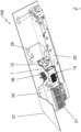
- Fig. 1 shows an overall view of the door drive 100 as it can be installed in a building, which also includes installation on ships and in aircraft, and a door drive 100 of this type serves, for example, as a drive for an automatic sliding door system.
- the basic structure of the door drive 100 is formed by a carrier profile 27, which is shown in shortened form for ease of viewing, and the essential upper part of the L-shaped support profile 27 is shown cut open in order to make the other essential components of the door drive 100 visible.
- the door drive 100 has a motor unit 1 as a central component, and the motor unit 1 has the basic shape of a cuboid 14, which forms the housing 10 of the motor unit 1.
- a pulley 36 is arranged on the motor unit 1, over which a toothed belt can be placed, with which the connection to the wing element(s), for example the glass sliding elements, is finally established.
- the door drive 100 Adjacent to the motor unit 1, the door drive 100 has a power supply 21 and a controller 22, and the power supply 21 and the controller 22 are arranged on opposite sides of the motor unit 1.
- the motor unit 1 is fastened to the support profile 27 with a first flange element 25, wherein the first flange element 25 also accommodates the power supply 21.
- the motor unit 1 is connected to the support profile 27 with a second flange element 26, wherein the second flange element 26 also accommodates the controller 22.
- the design of a single flange is also possible in order to accommodate at least the motor unit 1, the power supply 21 and the controller 22; it is also possible for the motor unit, the power supply 21 and/or the controller 22 to each have associated separate flange elements for arrangement in or on the support profile 27.
- Fig. 2 shows a perspective view of the isolated motor unit 1 with the housing 10, and outside the housing 10 is located in the illustration shows the pulley 36 on the top for coupling a toothed belt above the front face 20 of the housing 10.
- the housing 10 of the motor unit 1 has a first upper housing half 15 and a second lower housing half 16, which are designed in the same way by way of example, but do not have to be designed in the same way within the scope of the invention.
- the housing 10 is laterally delimited by a first side surface 23 and an opposite second side surface 24, and the flange elements 25 and 26 can be arranged on the side surfaces 23 and 24, which in Fig. 1 are shown.
- the cuboid 14 formed with the housing 10 has corner areas 28, and screw holes 29 for fastening the flange elements 25, 26 by means of screw elements are made in the respective corner areas 28, of which two screw holes 29 are numbered as examples. Furthermore, screw arrangements 30 for screwing the housing halves 15 and 16 together are located in the corner areas.
- the cuboid 14 is determined by the longitudinal edge 17, the width edge 18 and the height edge 19, whereby the side surfaces 23, 24 are spanned by the width edge 18 and the height edge 19.
- the front surface which is spanned by the longitudinal edge 17 and the vertical edge 19, has a window-shaped recess 37 from which a surface section 33 of the stator (not shown in the view) protrudes, wherein in connection with the stator 11 on Fig. 3
- the outwardly facing surface section 33 of the stator 11 serves for heat-transferring contact with another body, for example with the carrier profile 27 or with another, separate heat sink. This means that despite the essentially closed housing 10, the upper and lower housing half 15,16 of the stator 11 can be brought into direct heat-transferring contact with an engine component.
- the stator 11 as shown in Fig. 3 is screwed to the lower housing half 16 with the screw arrangement 31, and on the front and on the back of the stator 11 there are respective surface sections 33 in an opposite arrangement, which form a surface section of the outer skin of the motor unit 1 as described above.
- stator 11 with the rotor 12 arranged inside the stator 11 is shown through the removed first housing half 15, wherein the rotor 12 is formed in one piece with the output shaft 13, which is led out of the upper housing half 15, and the part of the output shaft 13 extending out of the end face 20 of the housing 10 receives the pulley 36.
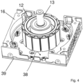
- Fig. 4 shows in conjunction with Fig. 3 in a further illustration, the lower housing half 16, wherein the rotor 12 is also shown with the output shaft 13.
- the housing half 16 Within the housing half 16, but also in a manner not shown in detail in the housing half 15, there is a substantially ring-shaped receiving area 38 in which the stator 11 is received.
- a heat transfer gap 32 is shown, which results as an at least partially circumferential annular gap between the outside of the stator 11 and the inner surface of the receiving area 38.
- the stator 11 heats up due to the current flowing through the winding on the stator 11 (not shown in detail), and the heat from the stator 11 can be dissipated by the very small Heat transfer gap 32 into the housing halves 15, 16.
- the heat transfer gap 32 is advantageously designed as a transition fit.
- the circuit board 39 is attached to the housing 10 of the motor unit 1 with holding elements.
Landscapes
- Engineering & Computer Science (AREA)
- Power Engineering (AREA)
- Power-Operated Mechanisms For Wings (AREA)
- Connection Of Motors, Electrical Generators, Mechanical Devices, And The Like (AREA)
Description
- Die Erfindung betrifft eine Türanlage mit einem Türantrieb, aufweisend eine Motoreinheit mit einem Gehäuse, in dem ein Stator ruhend aufgenommen ist und wobei ein Rotor drehbeweglich im Gehäuse angeordnet ist, der eine Abtriebswelle aufweist, wobei die Abtriebswelle mit dem Flügelelement antreibend in Wirkverbindung bringbar ist. Weiterhin betrifft die Erfindung eine Türanlage mit einem solchen Türantrieb, aufweisend wenigstens ein Flügelelement, mit dem der Türantrieb antreibend in Wirkverbindung steht.
- Aus der
DE 10 2008 046 062 A1 ist ein Türantrieb zur Anordnung an einer Türanlage bekannt, und der Antrieb dient zur Bewegung von Flügelelementen der Türanlage, die als automatische Schiebetür ausgebildet ist. Der Türantrieb weist hierfür eine Motoreinheit mit einem Gehäuse auf, und an das Gehäuse der Motoreinheit ist eine Getriebeeinheit angebracht, die als Schneckenradgetriebe ausgeführt ist. Damit ist die Motoreinheit als schnelldrehender Motor konzipiert, und mit der Getriebeeinheit wird die höhere Drehzahl des Rotors der Motoreinheit reduziert auf eine geringere Drehzahl zum Antrieb einer Riemenscheibe, die auf eine Abtriebswelle der Getriebeeinheit aufgesetzt ist. - Über die Riemenscheibe wird ein Zahnriemen gelegt, der mit den Flügelelementen der automatischen Schiebetür verbunden wird. Da die Motoreinheit schnelldrehend ausgelegt ist, und die Drehzahl auf die Riemenscheibe reduziert werden muss, ist in Verbindung mit dem Motor die Getriebeeinheit notwendig, wodurch zusätzlicher Bauraum erforderlich wird, und wodurch die Konstruktion des Türantriebs komplexer wird. Die räumliche Dimensionierung des Türantriebs muss an die Notwendigkeit der Getriebeeinheit angepasst werden, und da der Motor eine zylinderförmige Grundform aufweist, nimmt dieser einen Bauraum ein, der in Bezug auf seine Einbauumgebung keine optimale Raumnutzung ermöglicht. Gleiches gilt für ein Schneckenradgetriebe, das insbesondere in Verbindung mit dem Motor sehr bauraumintensiv ist.
- Einen weiteren Türantrieb offenbart die
DE 10 2014 115 932 A1 , und der Türantrieb weist als Grundkörper einen einteiligen quaderförmigen Körper auf, in den Aussparungen zu der Aufnahme einer Motoreinheit und einer Getriebestufe eingebracht sind. Zur weiteren Aufnahme einer Steuerung, einem Netzteil und dergleichen sind in dem Block weitere Aussparungen und Öffnungen vorgesehen. Der quaderförmige Körper bildet also ein Gehäuse als Träger der einzelnen Komponenten des Türantriebes und ist über der gesamten Abmessung des Antriebes einteilig und gewissermaßen monolithisch ausgeführt. - Aus der
DE 10 2014 115 921 A1 ist ein Türantrieb mit einer Antriebseinheit bekannt, wobei die Antriebseinheit zumindest einen elektrischen Antrieb umfasst. Weiterhin weist die Antriebseinheit ein Gehäuse auf. Das Gehäuse weist eine Gehäuseausnehmung auf, in die eine Steuerungsvorrichtung einbringbar ist. Auch die Antriebseinheit und ein Getriebe sind in die Gehäuseausnehmung einbringbar. Das Gehäuse der Antriebseinheit ist durch einen Grundkörper des Türantriebs selbst gebildet. - Aus der
EP 2 757 219 A2 ist ein Türantrieb für eine Türanlage bekannt. - Grundsätzlich wird bei der Konstruktion von Türantrieben zur Anordnung an oder zur Anordnung in Verbindung mit einer Türanlage das Ziel verfolgt, den Türantrieb möglichst kompakt und mit kleinen Abmessungen auszuführen, beispielsweise indem eine Getriebeeinheit oder eine Getriebestufe innerhalb des Türantriebs bereits vermieden wird. Türantriebe werden üblicherweise oberhalb der linear bewegbaren Flügelelemente einer automatischen Schiebetüranlage angeordnet und weisen ein Trägerprofil auf, das einen Grundkörper der Türanlage bildet und am Trägerprofil werden der Türantrieb integriert montiert und gleichermaßen die Flügelelemente linear geführt. Als Verbindungsmittel zwischen dem Türantrieb und den Flügelelementen dient in der Regel ein Zahnriemen, wobei auch andere Zugmittel wie Kettenverbindungen und dergleichen möglich sind. Der Türantrieb bildet dabei mit wenigstens dem Motor, einem Netzteil und einer Steuerung eine eigene Baueinheit, die mit der Anordnung am Trägerprofil in die Türanlage integriert wird.
- Um das Trägerprofil mit einer entsprechenden Blende, einem Gehäuse oder sonstigen Umbauteilen möglichst kleinbauend auszuführen, ist es von Vorteil, auch und insbesondere den Türantrieb selbst möglichst kompakt und mit kleinen Abmessungen auszuführen. Da jedoch Flügelelemente aus Glas große Massen erreichen können, muss der Türantrieb eine hohe Leistungsdichte aufweisen, um derartige Flügelelemente entsprechend stark beschleunigen und auch wieder verzögern zu können, damit die Türanlage auch mit großen Flügelelementen noch eine angemessene Dynamik erreicht.
- Für eine hohe Leistungsdichte und insbesondere einen geräuscharmen Betrieb bieten sich Motoreinheiten in Verbindung mit einem Zahnriemen als Direktantriebe an, bei denen auf der Abtriebswelle der Motoreinheit unmittelbar die Riemenscheibe aufgebracht wird, über die der Zahnriemen gelegt wird, der wiederum unmittelbar mit den Flügelelementen in Verbindung steht. Dadurch kann der Türantrieb geräuschminimal betrieben werden, da keine hohen Motordrehzahlen erreicht werden, und bei entsprechender Auslegung der Motoreinheit können Leistungsdichten bereitgestellt werden, die hinreichend sind, um Flügelelemente von beispielsweise 200kg bis 250kg für den Betrieb einer automatischen Schiebetür hinreichend stark zu beschleunigen und auch wieder zu verzögern.
- Motor-Getriebeeinheiten mit einer zylinderförmigen Motoraußenform und einem quer dazu liegenden Schneckendrahtgetriebe ermöglichen keine besonders hohe Integrationsdichte, insbesondere in Bezug auf die bereitstellbare Ausgangsleistung an der Abtriebswelle. Ferner gestaltet sich die weitere kompakte Anordnung eines Netzteiles, einer Steuerung und beispielsweise eines Bedienteils unter Einhaltung einer hohen Integrationsdichte als schwierig.
- Aufgabe der Erfindung ist die Schaffung eines Türantriebs mit einer Motoreinheit, die eine hohe Integrationsdichte und eine hohe Leistungsdichte aufweist, und wobei der Motor in Verbindung mit dem wenigstens einen Flügelelement insbesondere als Direktantrieb ausgeführt sein soll. Die hohe Integrationsdichte des Türantriebes soll zudem auch in der Anordnung der Motoreinheit in Verbindung mit einem Netzteil und einer Steuerung erreicht werden, sowie mit weiteren Komponenten, beispielsweise einem Bedienteil. Dabei soll ferner Berücksichtigung finden, dass der Türantrieb möglichst ohne größeren Raumbedarf in ein Trägerprofil einer Türanlage integriert werden kann, insbesondere um letzteres mit kleineren Abmessungen auszuführen.
- Diese Aufgabe wird ausgehend von einer Türanlage mit einem Türantrieb gemäß Anspruch 1 mit den jeweils kennzeichnenden Merkmalen gelöst. Vorteilhafte Weiterbildungen der Erfindung sind in den abhängigen Ansprüchen und in der Beschreibung angegeben.
- Die Erfindung schließt die technische Lehre ein, dass die Motoreinheit die Grundform eines Quaders aufweist, der wenigstens mittels zweier miteinander verbundener Gehäusehälften gebildet ist.
- Ein Quader im Sinne der Erfindung ist ein Körper, der von sechs Rechteckflächen begrenzt wird, wobei die Rechteckflächen im Wesentlichen, aber nicht vollständig plan sein sollten, also durchaus Anformungen, Wölbungen, Schrägungen, Rippen und dergleichen aufweisen können. Insofern ist im Sinne der Erfindung die Quaderform der Motoreinheit allenfalls annähernd im mathematischen Sinne zu verstehen; ein Rechteckkörper mit leichten Winkelabweichungen und Formabweichungen fällt damit auch noch unter dem Begriff des Quaders, ohne also am mathematischen Begriff eines Quaders zu haften. Da erfindungsgemäß auch nur die Grundform der Motoreinheit einen Quader bilden soll, kann die Grundform auch als eine Hüllform zu verstehen sein, ohne dass das Gehäuse der Motoreinheit die quaderförmige Hüllform exakt abbildet.
- Die erfindungsgemäß ausgestaltete Motoreinheit kann mit der Quaderform auf vorteilhafte Weise in einen Türantrieb integriert werden, und durch die gebildeten Seitenflächen, die Stirnfläche, sowie eine plane Rückseite ermöglichen einen einfachen Aufbau des Türantriebs mit unmittelbar angrenzenden weiteren Komponenten, insbesondere Komponenten wie das Netzteil, die Steuerung und dergleichen. Insbesondere lässt sich ein quaderförmiger Körper besonders vorteilhaft in oder an einem Trägerprofil anordnen, sodass der Türantrieb insgesamt mit kleineren Abmessungen dimensioniert werden kann.
- Die Gehäusehälften können halbschalenförmig ausgeführt sein, und werden die Gehäusehälften miteinander verbunden, vervollständigt sich der so gebildete Gehäusekörper zu einem Quader. Die Gehäusehälften müssen dabei nicht zwingend eine exakte Hälfte des Gehäuses bilden, und die Teilungsebene zwischen den Gehäusehälften muss nicht auf einer halben Höhe einer Höhenkante des Quaders liegen. Insofern können auch Gehäusehälften vorgesehen sein, die unterschiedlich bemaßt, gestaltet und dimensioniert sind, diese können jedoch in einer Weise aufeinander gebracht und verbunden werden, dass der Quader zur Bildung des Gehäuses entsteht, und so die Grundform der Motoreinheit bildet.
- Die Gehäusehälften sind so ausgestaltet, dass wenigstens der Stator und der Rotor innenseitig zwischen den Gehäusehälften aufgenommen sind. Die Gehäusehälften sind schalenartig ausgeführt, und diese werden unmittelbar miteinander verbunden, so dass ein umlaufender etwa rechteckförmiger Rand der jeweiligen Gehäusehälfte aufeinander gefügt wird.
- Erfindungsgemäß weist der Quader eine Längskante, eine Breitenkante und eine Höhenkante auf, wobei die Längskante größer ist als die Breitenkante und/oder wobei die Breitenkante größer ist als die Höhenkante. Beispielsweise weist die Breitenkante eine Länge von 70 % bis 98 %, insbesondere von 85 % bis 95 % von der Länge der Längskante auf. Die Höhenkante weist eine Länge von 30 % bis 60 %, insbesondere von 40 % bis 50 % von der Länge der Längskante auf. Beträgt die Länge der Längskante beispielsweise 100mm, so weist die Breitenkante eine Länge von beispielsweise 90mm auf, und die Höhenkante weist eine Länge von beispielsweise 40 mm bis 50 mm auf.
- Insbesondere dann, wenn die Breitenkante ein geringeres Maß aufweist als die Längskante, kann die Motoreinheit im Türantrieb so integriert werden, dass die Breitenkante sich in der Vertikalen erstreckt, sodass der Türantrieb insbesondere in Anordnung über den Flügelelementen mit einer geringen Bauhöhe ausgelegt werde kann, die bestimmt ist durch die Bauhöhe des Türantriebs, und die Bauhöhe des Türabtriebs ist wiederum bestimmt durch die Breite der Motoreinheit, also durch die Länge der Breitenkante.
- Mit weiterem Vorteil spannen die Längskante und die Breitenkante eine Stirnfläche auf, wobei die Abtriebswelle senkrecht auf der Stirnfläche hervorsteht. Auf dem hervorstehenden Abschnitt der Abtriebswelle ist eine Riemenscheibe aufgebracht, und die Stirnfläche kann frei von Befestigungsmitteln ausgeführt sein, sodass der Riemen möglichst nah über der Stirnfläche geführt werden kann, wenn die Riemenscheibe bis vor die Stirnfläche geführt ist.
- Mit weiterem Vorteil weist der Türantrieb wenigstens ein Netzteil und wenigstens eine Steuerung auf, wobei das Netzteil und die Steuerung zumindest mittelbar an den gegenüberliegenden Seitenflächen des Quaders angeordnet sind, wobei die gegenüberliegenden Seitenflächen über die Breitenkante und die Höhenkante des Quaders aufgespannt sind. Insofern sind das Netzteil und die Steuerung in der Verlängerung der Erstreckungsrichtung der Längskante des Quaders der Motoreinheit angeordnet, was dann vorteilhaft ist, wenn die Längskante der Motoreinheit sich parallel zur Längsrichtung eines Trägerprofils des Türantriebs erstreckt. In dieser Richtung ist die Integration des Türantriebs nicht so bauraumkritisch wie in einer Querrichtung hierzu, sodass die Längskante die größte Abmessung des Quaders der Motoreinheit aufweist. Die mittelbare Anordnung des Netzteiles und/oder der Steuerung an der Motoreinheit betrifft eine Anordnung, bei der wenigstens ein weiteres Bauteil zwischen dem Netzteil und/oder der Steuerung und der Motoreinheit vorhanden ist, beispielsweise eine Halterung oder ein Flansch.
- Auch ist es von Vorteil, die Motoreinheit im Verbund mit dem Netzteil und/oder der Steuerung elektrisch zu isolieren, sodass zusätzlich ein Isolierungselement an die Seitenflächen der Motoreinheit angrenzen kann.
- Es ist mit weiterem Vorteil ein erstes Flanschelement vorgesehen, das an der ersten Seitenfläche angeordnet ist und das Netzteil aufnimmt und/oder dass ein zweites Flanschelement vorgesehen ist, das an der zweiten Seitenfläche angeordnet ist und die Steuerung aufnimmt. Insbesondere ist somit die Motoreinheit über die beiden Flanschelemente im Türantrieb haltend aufgenommen. Durch die Anordnung der Flanschelemente an den Seitenflächen kann die Stirnfläche frei von Befestigungsmitteln und insbesondere frei von Flanschelementen ausgeführt werden, sodass der Zahnriemen, der über die Riemenscheibe gelegt ist, frei und möglichst nah über die Stirnfläche verlaufen kann.
- Der Grundkörper des Türantriebs wird mit besonderem Vorteil mit dem Trägerprofil gebildet, das beispielsweise ein L-förmiges Aluminiumprofil bildet, und die Motoreinheit kann in Bezug auf eine spätere Einbaulage so zum Trägerprofil ausgerichtet und an diesem angeordnet sein, dass die Abtriebswelle eine horizontale Erstreckung aufweist. Dadurch ergibt sich ein Verlauf des Riemens mit vertikal übereinander angeordneten Riemensträngen. Diese Ausführung ist vorteilhaft in Bezug auf die geforderte Bewegung der Flügelelemente und vorteilhaft in Bezug auf eine Integration einer Blockiereinrichtung für die Flügelelemente, die mit den Riemen in Verbindung gebracht werden.
- Die Flanschelemente sind so ausgeführt, dass diese am Trägerprofil befestigt sind, sodass die Motoreinheit mittels der Flanschelemente am Trägerprofil angeordnet wird. Die Flanschelemente bilden im Stanz-Biegeverfahren hergestellte Blechbauteile, die so geformt sind, dass der Motor über seine Seitenflächen mit den Flanschelementen im Trägerprofil angebracht werden kann, und die Blechelemente nehmen zugleich auf der einen Seite der Motoreinheit das Netzteil und auf einer gegenüberliegenden Seite des Motors die Steuerung auf. Ferner können ein Bedien- und Anzeigenteil und weitere Komponenten zum Betrieb des Türantriebes mittels der Flanschelemente gleichermaßen aufgenommen werden.
- Der Stator der Motoreinheit weist eine im Wesentlichen runde Grundform auf, sodass im Körper des Quaders Eckbereiche gebildet werden, in denen Schraubbohrungen zur Anordnung der Flanschelemente und/oder eine Schraubanordnung zur Verschraubung der Gehäusehälften aufeinander und/oder eine Schraubanordnung zur Verschraubung des Stators an einer der Gehäusehälften angeordnet sind. Die Ausgestaltung der Motoreinheit mit einem im Wesentlichen ringförmigen Stator und einem quaderförmigen Gehäuse ergibt somit vorteilhaft die Möglichkeit, in den Eckbereichen die Befestigungsmittel zu integrieren, sodass die Motoreinheit selbst ebenfalls eine hohe räumliche Integrationsdichte aufweist und übrige Strukturbereiche in räumlicher Hinsicht nicht ungenutzt bleiben. Die Seitenflächen können zur weiter verbesserten Entwärmung eine Rippenstruktur aufweisen, wodurch die Anbringung der Flanschelemente nicht behindert wird.
- Der Stator weist ungeachtet kleinerer Abweichungen wie Schraubenaufnahmen und dergleichen eine im Wesentlichen ringförmige Grundstruktur auf und der Stator ist in wenigstens einer der Gehäusehälften so aufgenommen, dass zwischen der radialen Außenseite des Stators und dem innenseitigen Aufnahmebereich der Gehäusehälfte ein wenigstens teilweise umlaufender Wärmeübergangsspalt ausgebildet ist. Dieser Wärmeübergangsspalt ist, um als solcher zur Wärmeübergabe vom Stator in die zumindest eine oder in beide Gehäusehälften zu dienen, mit Werten von beispielsweise zwischen - 0,05 mm bis 0,1 mm ausgelegt, sodass eine Übergangspassung zwischen dem Stator und dem Aufnahmebereich des Stators in der Gehäusehälfte oder in beiden Gehäusehälften entsteht. Wärme, die im Stator durch den Betrieb der Motoreinheit entsteht, kann auf vorteilhafte Weise an die Gehäusehälften übergehen und über diese an die Umgebung abgegeben werden.
- Mit weiterem Vorteil weist der Stator Flächenabschnitte auf zwei sich gegenüberliegenden Außenseiten des Quaders auf, wobei die Flächenabschnitte mit fensterartigen Aussparungen in den sich gegenüberliegenden Außenseiten des Quaders korrespondieren. Dabei ist wenigstens eines der Flächenabschnitte des Stators durch die fensterartige Aussparung hindurch in einen Wärmeübergangskontakt mit dem Trägerprofil gebracht. Alternativ oder zusätzlich kann wenigstens einer der Flächenabschnitte des Stators durch die fensterartige Aussparung hindurch in einen Wärmeübergangskontakt mit einem separaten Kühlkörper gebracht werden.
- Die Türanlage kann ein Verbindungselement zum Verbinden mit einem Flügelelement aufweisen. Zusätzlich oder alternativ kann die Türanlage wenigstens ein Flügelelement, mit dem der Türantrieb antreibend in Wirkverbindung steht, aufweisen.
- Beispielsweise kann die Türanlage als eine Schiebetüranlage ausgebildet sein. Die Schiebetüranlage kann einen Riemen, insbesondere einen Zahnriemen, umfassen. Das Verbindungselement kann zumindest mittelbar mit dem Riemen verbunden sein. Das Verbindungselement kann als Läufer, insbesondere als Rollwagen, ausgebildet sein. Das Verbindungselement kann in einer Schiene, insbesondere in einer Schiene des Trägerprofils, laufen. Der Riemen kann zwischen Riemenscheiben der Türanlage gespannt sein.
- Weitere, die Erfindung verbessernde Maßnahmen werden nachstehend gemeinsam mit der Beschreibung eines bevorzugten Ausführungsbeispiels der Erfindung anhand der Figuren näher dargestellt. Es zeigt:
- Fig. 1
- eine Gesamtansicht des Türantriebs einer erfindungsgemäßen Türanlage mit einer Motoreinheit, die die erfindungsgemäße Bauform aufweist,
- Fig. 2
- eine perspektivische Ansicht der Motoreinheit einer erfindungsgemäßen Türanlage,
- Fig. 3
- eine perspektivische Ansicht der Motoreinheit gemäß
Fig. 2 , wobei eine Gehäusehälfte in der Ansicht entfernt wurde und - Fig. 4
- eine Ansicht einer weiteren Gehäusehälfte der Motoreinheit mit einem Stator und einer Abtriebswelle.
-
Fig. 1 zeigt eine Gesamtansicht des Türantriebs 100, wie dieser in einem Gebäude installiert werden kann, womit auch die Installation auf Schiffen und in Flugzeugen umfasst sein soll, und ein Türantrieb 100 dieser Art dient beispielsweise als Antrieb für eine automatische Schiebetüranlage. Die Grundstruktur des Türantriebs 100 bildet ein Trägerprofil 27, welches zur einfacheren Ansicht verkürzt dargestellt ist, zudem ist der wesentliche obere Teil des L-förmigen Trägerprofils 27 aufgeschnitten gezeigt, um die weiteren vorliegend wesentlichen Komponenten des Türantriebs 100 sichtbar zu machen. - Als zentraler Bestandteil weist der Türantrieb 100 eine Motoreinheit 1 auf, und die Motoreinheit 1 besitzt die Grundform eines Quaders 14, der das Gehäuse 10 der Motoreinheit 1 bildet. Um einen Abtrieb und damit eine Verbindung zu einem nicht näher dargestellten Flügelelement einer Türanlage zu ermöglichen, ist an der Motoreinheit 1 eine Riemenscheibe 36 angeordnet, über die ein Zahnriemen gelegt werden kann, mit dem schließlich die Verbindung zu dem oder den Flügelelementen, beispielsweise den Glasschiebeelementen, hergestellt wird.
- Benachbart zur Motoreinheit 1 weist der Türantrieb 100 ein Netzteil 21 und eine Steuerung 22 auf, und das Netzteil 21 und die Steuerung 22 sind an sich gegenüberliegenden Seiten der Motoreinheit 1 angeordnet. Die Motoreinheit 1 ist mit einem ersten Flanschelement 25 am Trägerprofil 27 befestigt, wobei das erste Flanschelement 25 zugleich das Netzteil 21 mit aufnimmt. Weiterhin ist die Motoreinheit 1 mit einem zweiten Flanschelement 26 mit dem Trägerprofil 27 verbunden, wobei das zweite Flanschelement 26 zugleich die Steuerung 22 aufnimmt. Alternativ ist auch die Ausführung eines einzigen Flansches möglich, um wenigstens die Motoreinheit 1, das Netzteil 21 und die Steuerung 22 aufzunehmen, ferner besteht die Möglichkeit, dass die Motoreinheit, das Netzteil 21 und/oder die Steuerung 22 jeweils zugeordnete separate Flanschelemente zur Anordnung im oder am Trägerprofil 27 aufweisen.
-
Fig. 2 zeigt eine perspektivische Ansicht der vereinzelten Motoreinheit 1 mit dem Gehäuse 10, und außerhalb des Gehäuses 10 befindet sich in der Darstellung oberseitig die Riemenscheibe 36 zur Ankopplung eines Zahnriemens oberhalb der Stirnfläche 20 des Gehäuses 10. Das Gehäuse 10 der Motoreinheit 1 weist eine erste obere Gehäusehälfte 15 und eine zweite untere Gehäusehälfte 16 auf, die beispielhaft gleichartig ausgeführt sind, im Rahmen der Erfindung aber nicht gleichartig ausgeführt sein müssen. Seitlich ist das Gehäuse 10 begrenzt durch eine erste Seitenfläche 23 und eine gegenüberliegende zweite Seitenfläche 24, und an den Seitenflächen 23 und 24 können die Flanschelemente 25 und 26 angeordnet werden, die inFig. 1 gezeigt sind. - Der mit dem Gehäuse 10 gebildete Quader 14 weist Eckbereich 28 auf, und in den jeweiligen Eckbereichen 28 sind Schraubbohrungen 29 zur Befestigung der Flanschelemente 25, 26 mittels Schraubelementen eingebracht, von denen zwei Schraubbohrungen 29 beispielhaft beziffert sind. Weiterhin befinden sich in dem Eckbereichen Schraubanordnungen 30 zur Verschraubung der Gehäusehälften 15 und 16 miteinander.
- Der Quader 14 ist bestimmt durch die Längskante 17, die Breitenkante 18 und die Höhenkante 19, wobei die Seitenflächen 23, 24 aufgespannt werden durch die Breitenkante 18 und die Höhenkante 19.
- Die vorderseitige Fläche, die durch die Längskante 17 und die Höhenkante 19 aufgespannt wird, weist eine fensterförmige Aussparung 37 auf, aus der ein Flächenabschnitt 33 des in der Ansicht nicht dargestellten Stators herausragt, wobei in Zusammenhang mit dem Stator 11 auf
Fig. 3 hingewiesen wird. Der nach außen weisende Flächenabschnitt 33 des Stators 11 dient zum wärmeübertragenden Kontakt mit einem weiteren Körper, beispielsweise mit dem Trägerprofil 27 oder mit einem weiteren, separaten Kühlkörper. Dadurch kann trotz des im Wesentlichen geschlossen ausgeführten Gehäuses 10 mit der oberen und unteren Gehäusehälfte 15,16 der Stator 11 in direkten wärmeübertragenden Kontakt mit einem Motorumbauteil gebracht werden. - Der Stator 11 gemäß der Darstellung in
Fig. 3 ist mit der unteren Gehäusehälfte 16 mit der Schraubanordnung 31 verschraubt, und auf der Vorderseite sowie auf der Rückseite des Stators 11 befinden sich in gegenüberliegender Anordnung jeweilige Flächenabschnitte 33, die wie obenstehende beschrieben einen Flächenabschnitt der Außenhaut der Motoreinheit 1 bilden. - Durch die entnommene erste Gehäusehälfte 15 ist der Stator 11 mit dem innerhalb des Stators 11 angeordneten Rotor 12 und gezeigt, wobei der Rotor 12 einheitlich ausgebildet ist mit der Abtriebswelle 13, die aus der oberen Gehäusehälfte 15 herausgeführt ist, und der sich aus der Stirnfläche 20 des Gehäuses 10 heraus erstreckende Teil der Abtriebswelle 13 nimmt die Riemenscheibe 36 auf.
-
Fig. 4 zeigt in Zusammenschau mitFig. 3 in einer weiteren Darstellung die untere Gehäusehälfte 16, wobei weiterhin der Rotor 12 mit der Abtriebswelle 13 gezeigt ist. Innerhalb der Gehäusehälfte 16, jedoch auch in nicht näher gezeigter Weise in der Gehäusehälfte 15, befindet sich ein im Wesentlichen ringförmiger Aufnahmebereich 38, in dem der Stator 11 aufgenommen ist. InFig. 3 ist ein Wärmeübergangsspalt 32 gezeigt, der sich als zumindest teilweise umlaufender Ringspalt zwischen der Außenseite des Stators 11 und der Innenmantelfläche des Aufnahmebereiches 38 ergibt. - Wird die Motoreinheit 1 betrieben, so erwärmt sich der Stator 11 durch eine Bestromung der nicht näher gezeigten Wicklung auf dem Stator 11, und die Wärme aus dem Stator 11 kann mit dem sehr klein bemessenen Wärmeübergangsspalt 32 in die Gehäusehälften 15, 16 übergehen. Der Wärmeübergangsspalt 32 ist dabei vorteilhafterweise als Übergangspassung ausgeführt. Auf der der Stirnseite 20 gegenüberliegenden Rückseite des Quaders 14 befindet sich eine Leiterkarte 39, auf der Leiterbahnen angeordnet sind, die insbesondere zur Kontaktierung und Beschaltung der Wicklung des Stators 11 dienen. Die Leiterkarte 39 ist dabei mit Haltelementen am Gehäuse 10 der Motoreinheit 1 befestigt.
- Die Erfindung beschränkt sich in ihrer Ausführung nicht auf das vorstehend angegebene bevorzugte Ausführungsbeispiel. Vielmehr ist eine Anzahl von Varianten denkbar, welche von der dargestellten Lösung auch bei grundsätzlich anders gearteten Ausführungen Gebrauch macht, solange sie im Rahmen des von den Patentansprüchen gesteckten Schutzbereichs liegen.
-
- 100
- Türantrieb
- 1
- Motoreinheit
- 10
- Gehäuse
- 11
- Stator
- 12
- Rotor
- 13
- Abtriebswelle
- 14
- Quader
- 15
- Gehäusehälfte
- 16
- Gehäusehälfte
- 17
- Längskante
- 18
- Breitenkante
- 19
- Höhenkante
- 20
- Stirnfläche
- 21
- Netzteil
- 22
- Steuerung
- 23
- Seitenfläche
- 24
- Seitenfläche
- 25
- erstes Flanschelement
- 26
- zweites Flanschelement
- 27
- Trägerprofil
- 28
- Eckbereich
- 29
- Schraubbohrung
- 30
- Schraubanordnung
- 31
- Schraubanordnung
- 32
- Wärmeübergangsspalt
- 33
- Flächenabschnitt
- 34
- Außenseite
- 35
- Aussparung
- 36
- Riemenscheibe
- 37
- fensterförmige Aussparung
- 38
- Aufnahmebereich
- 39
- Leiterkarte
Claims (12)
- Türanlage mit einem Türantrieb (100) aufweisend wenigstens ein Verbindungselement zum Verbinden mit einem Flügelelement und/oder wenigstens ein Flügelelement, mit dem der Türantrieb (100) antreibend in Wirkverbindung steht, wobei mit dem Türantrieb (100) das zumindest eine Flügelelement der Türanlage bewegbar ist, wobei der Türantrieb (100) eine Motoreinheit (1) mit einem Gehäuse (10) aufweist, in dem ein Stator (11) ruhend aufgenommen ist und wobei ein Rotor (12) drehbeweglich im Gehäuse (10) angeordnet ist, der eine Abtriebswelle (13) aufweist, wobei die Abtriebswelle (13) mit dem Flügelelement antreibend in Wirkverbindung bringbar ist,
wobei die Motoreinheit (1) die Grundform eines Quaders (14) aufweist, der wenigstens mittels zweier miteinander verbundener Gehäusehälften (15, 16) gebildet ist, und wobei der Stator (11) und der Rotor (12) innenseitig zwischen den Gehäusehälften (15, 16) aufgenommen sind, dadurch gekennzeichnet, dass die Gehäusehälften (15, 16) schalenartig ausgeführt sind und unmittelbar aneinander anliegen, sodass ein umlaufender etwa rechteckförmiger Rand der jeweiligen Gehäusehälfte aufeinander gefügt ist, und wobei der Quader (14) eine Längskante (17), eine Breitenkante (18) und eine Höhenkante (19) aufweist, wobei die Längskante (17) größer ist als die Breitenkante (18) und/oder wobei die Breitenkante (18) größer ist als die Höhenkante (19). - Türanlage nach Anspruch 1, dadurch gekennzeichnet, dass die Breitenkante (18) eine Länge von 70% bis 98% und/oder 85% bis 95% der Länge der Längskante (17) aufweist und/oder dass die Höhenkante (19) eine Länge von 30% bis 60% und/oder 40% bis 50% der Länge der Längskante (17) aufweist.
- Türanlage nach Anspruch 1 oder 2, dadurch gekennzeichnet, dass die Längskante (17) und die Breitenkante (18) eine Stirnfläche (20) aufspannen, wobei die Abtriebswelle (13) senkrecht aus der Stirnfläche (20) hervorsteht.
- Türanlage nach einem der vorgenannten Ansprüche, dadurch gekennzeichnet, dass wenigstens ein Netzteil (21) und eine Steuerung (22) vorhanden sind, wobei das Netzteil (21) und die Steuerung (22) zumindest mittelbar an gegenüberliegenden Seitenflächen (23, 24) des Quaders (14) angeordnet sind, wobei die gegenüberliegenden Seitenflächen (23, 24) über die Breitenkante (18) und die Höhenkante (19) des Quaders (14) aufgespannt sind.
- Türanlage nach einem der vorgenannten Ansprüche, dadurch gekennzeichnet, dass ein erstes Flanschelement (25) vorgesehen ist, das an einer ersten Seitenfläche (24) angeordnet ist und das Netzteil (21) aufnimmt und/oder dass ein zweites Flanschelement (26) vorgesehen ist, das an einer zweiten Seitenfläche (24) angeordnet ist und die Steuerung (22) aufnimmt, wobei die Motoreinheit (1) über die beiden Flanschelemente (25, 26) im Türantrieb (100) haltend aufgenommen ist.
- Türanlage nach einem der vorgenannten Ansprüche, dadurch gekennzeichnet, dass ein Grundkörper des Türantriebes (100) mittels eines Trägerprofils (27) gebildet ist, wobei die Motoreinheit (1) in Bezug auf eine spätere Einbaulage so zum Trägerprofil (27) ausgerichtet ist, dass die Abtriebswelle (13) eine horizontale Erstreckung aufweist.
- Türanlage nach Anspruch 6, dadurch gekennzeichnet, dass die Flanschelemente (25, 26) am Trägerprofil (27) befestigt sind, sodass die Motoreinheit (1) mittels der Flanschelemente (25, 26) am Trägerprofil (27) angeordnet ist.
- Türanlage nach einem der vorgenannten Ansprüche, dadurch gekennzeichnet, dass der Stator (11) eine im Wesentlichen runde Grundform aufweist, sodass im Quader (14) Eckbereiche (28) gebildet sind, in denen Schraubbohrungen (29) zur Anordnung der Flanschelemente (25, 26) und/oder eine Schraubanordnung (30) zur Verschraubung der Gehäusehälften (15, 16) aufeinander und/oder eine Schraubanordnung (31) zur Verschraubung des Stators (11) an einer der Gehäusehälften (15, 16) angeordnet sind.
- Türanlage nach einem der vorgenannten Ansprüche, dadurch gekennzeichnet, dass der Stator (11) eine ringförmige Grundstruktur aufweist und in wenigstens einer der Gehäusehälften (15, 16) aufgenommen ist, wobei zwischen der radialen Außenseite des Stators (11) und der Innenseite der Gehäusehälfte (15, 16) ein wenigstens teilweise umlaufender Wärmeübergangsspalt (32) ausgebildet ist.
- Türanlage nach einem der vorgenannten Ansprüche, dadurch gekennzeichnet, dass der Stator (11) Flächenabschnitte (33) auf sich gegenüberliegenden Außenseiten (34) des Quaders (14) aufweist, wobei die Flächenabschnitte (33) mit fensterartigen Aussparungen (35) in den sich gegenüberliegenden Außenseiten (34) des Quaders (14) korrespondieren.
- Türanlage nach Anspruch 10, dadurch gekennzeichnet, dass wenigstens einer der Flächenabschnitte (33) des Stators (11) durch die fensterartige Aussparung (35) hindurch in einen Wärmeübergangskontakt mit dem Trägerprofil (27) gebracht ist.
- Türanlage nach Anspruch 10 oder 11, dadurch gekennzeichnet, dass wenigstens einer der Flächenabschnitte (33) des Stators (11) durch die fensterartige Aussparung (35) hindurch in einen Wärmeübergangskontakt mit einem separaten Kühlkörper gebracht ist.
Priority Applications (7)
| Application Number | Priority Date | Filing Date | Title |
|---|---|---|---|
| EP19214422.8A EP3835528B1 (de) | 2019-12-09 | 2019-12-09 | Türanlage mit einer motoreinheit, aufweisend eine vorteilhafte grundform |
| ES19214422T ES3014173T3 (en) | 2019-12-09 | 2019-12-09 | Door assembly with a motor unit having a beneficial basic design |
| AU2020400846A AU2020400846A1 (en) | 2019-12-09 | 2020-11-25 | Door drive with a motor unit, having an advantageous basic shape |
| PCT/EP2020/083346 WO2021115785A1 (de) | 2019-12-09 | 2020-11-25 | Türantrieb mit einer motoreinheit, aufweisend eine vorteilhafte grundform |
| CN202080083867.1A CN114761656B (zh) | 2019-12-09 | 2020-11-25 | 包括具有有利的基本形状的马达单元的门驱动器 |
| US17/782,861 US20220403691A1 (en) | 2019-12-09 | 2020-11-25 | Door drive with a motor unit, having an advantageous basic shape |
| US18/890,295 US20250012127A1 (en) | 2019-12-09 | 2024-09-19 | Door drive with a motor unit, having an advantageous basic shape |
Applications Claiming Priority (1)
| Application Number | Priority Date | Filing Date | Title |
|---|---|---|---|
| EP19214422.8A EP3835528B1 (de) | 2019-12-09 | 2019-12-09 | Türanlage mit einer motoreinheit, aufweisend eine vorteilhafte grundform |
Publications (3)
| Publication Number | Publication Date |
|---|---|
| EP3835528A1 EP3835528A1 (de) | 2021-06-16 |
| EP3835528B1 true EP3835528B1 (de) | 2025-02-12 |
| EP3835528C0 EP3835528C0 (de) | 2025-02-12 |
Family
ID=68840899
Family Applications (1)
| Application Number | Title | Priority Date | Filing Date |
|---|---|---|---|
| EP19214422.8A Active EP3835528B1 (de) | 2019-12-09 | 2019-12-09 | Türanlage mit einer motoreinheit, aufweisend eine vorteilhafte grundform |
Country Status (5)
| Country | Link |
|---|---|
| US (2) | US20220403691A1 (de) |
| EP (1) | EP3835528B1 (de) |
| AU (1) | AU2020400846A1 (de) |
| ES (1) | ES3014173T3 (de) |
| WO (1) | WO2021115785A1 (de) |
Families Citing this family (1)
| Publication number | Priority date | Publication date | Assignee | Title |
|---|---|---|---|---|
| CN117489224A (zh) * | 2023-11-13 | 2024-02-02 | 上海驰助汽车零部件有限公司 | 一种剪刀门铰链系统及包含其的车辆 |
Citations (1)
| Publication number | Priority date | Publication date | Assignee | Title |
|---|---|---|---|---|
| EP3534504A1 (de) * | 2018-03-02 | 2019-09-04 | Black & Decker Inc. | Motor mit externem kühlkörper für ein elektrowerkzeug |
Family Cites Families (17)
| Publication number | Priority date | Publication date | Assignee | Title |
|---|---|---|---|---|
| US4893435A (en) * | 1989-04-07 | 1990-01-16 | Remote-A-Matic, Inc. | Low profile sliding door opener |
| US5797471A (en) * | 1996-07-19 | 1998-08-25 | Montgomery Kone Inc. | Linear door drive operator |
| JP3736166B2 (ja) * | 1999-01-06 | 2006-01-18 | セイコーエプソン株式会社 | ステッピングモータ |
| TW432773B (en) * | 1999-05-20 | 2001-05-01 | Shiu Jiun Fu | High-efficiency, high-torque, and high-support external rotator motor |
| KR100407006B1 (ko) * | 2000-04-06 | 2003-11-28 | 스미도모쥬기가이고교 가부시키가이샤 | 벨트식 도어개폐용 구동장치 |
| DE10247277A1 (de) * | 2002-10-10 | 2004-04-22 | Dorma Gmbh + Co. Kg | Elektromechanischer Antrieb für eine Tür |
| US7331141B2 (en) * | 2004-06-14 | 2008-02-19 | Door Control Services, Inc. | Automatic door control apparatus |
| DE102008046062A1 (de) | 2008-09-08 | 2010-03-11 | Dorma Gmbh + Co. Kg | Nachrüstsatz mit einer Antriebseinheit, insbesondere für eine automatische Schiebetür |
| ITBO20080591A1 (it) * | 2008-09-30 | 2010-04-01 | Calibe Srl | Porta ad anta scorrevole motorizzata per cabina doccia |
| US8384261B2 (en) * | 2009-12-11 | 2013-02-26 | Minebea Co., Ltd. | Stepping motor including a connection structure of a stator yoke and a front plate |
| CN103546013A (zh) * | 2010-06-11 | 2014-01-29 | 日本电产伺服有限公司 | 旋转电机 |
| DE102011007369A1 (de) * | 2011-04-14 | 2012-10-18 | Siemens Aktiengesellschaft | Vorrichtung und Verfahren zum Antrieb einer Tür |
| US8800206B2 (en) * | 2012-08-20 | 2014-08-12 | New Visions Yezirot Aluminum, Ltd. | Motorized closure assembly |
| DE102013200877A1 (de) * | 2013-01-21 | 2014-07-24 | Gebr. Willach Gmbh | Antriebsvorrichtung für eine Schiebetür |
| DE102014115932A1 (de) | 2014-10-31 | 2016-05-04 | Dorma Deutschland Gmbh | Türantrieb |
| DE102014115921A1 (de) * | 2014-10-31 | 2016-05-04 | Dorma Deutschland Gmbh | Türantrieb |
| US10392854B2 (en) * | 2016-02-11 | 2019-08-27 | Technology Construction, Inc. | Systems and methods for an automatic sliding door having a slide and rail assembly |
-
2019
- 2019-12-09 ES ES19214422T patent/ES3014173T3/es active Active
- 2019-12-09 EP EP19214422.8A patent/EP3835528B1/de active Active
-
2020
- 2020-11-25 US US17/782,861 patent/US20220403691A1/en not_active Abandoned
- 2020-11-25 AU AU2020400846A patent/AU2020400846A1/en active Pending
- 2020-11-25 WO PCT/EP2020/083346 patent/WO2021115785A1/de not_active Ceased
-
2024
- 2024-09-19 US US18/890,295 patent/US20250012127A1/en active Pending
Patent Citations (1)
| Publication number | Priority date | Publication date | Assignee | Title |
|---|---|---|---|---|
| EP3534504A1 (de) * | 2018-03-02 | 2019-09-04 | Black & Decker Inc. | Motor mit externem kühlkörper für ein elektrowerkzeug |
Also Published As
| Publication number | Publication date |
|---|---|
| US20220403691A1 (en) | 2022-12-22 |
| US20250012127A1 (en) | 2025-01-09 |
| WO2021115785A1 (de) | 2021-06-17 |
| CN114761656A (zh) | 2022-07-15 |
| AU2020400846A1 (en) | 2022-06-09 |
| ES3014173T3 (en) | 2025-04-21 |
| EP3835528A1 (de) | 2021-06-16 |
| EP3835528C0 (de) | 2025-02-12 |
Similar Documents
| Publication | Publication Date | Title |
|---|---|---|
| DE102012214270B4 (de) | Schubkette, Antriebsvorrichtung zur linearen Bewegung sowie Untersuchungsbett | |
| EP3574726B1 (de) | Kühlvorrichtung und robotersteuervorrichtung mit einer solchen kühlvorrichtung | |
| EP3015634B1 (de) | Türantrieb | |
| EP2687376B1 (de) | Nummerierwerk | |
| DE10139631B4 (de) | Längseinstellvorrichtung für einen Fahrzeugsitz | |
| EP3121485B1 (de) | Kompakter elektrischer linearantrieb für eine zahnstange, insbesondere eines hydraulikventils, und verfahren zu seiner montage | |
| DE102015207127A1 (de) | Verriegelungs-Struktur zwischen einem Element, das zu lagern ist und einem Lagerungs-Körper | |
| WO2001031157A1 (de) | Elektronische steuerungseinrichtung zur ansteuerung elektrischer aggregate von kraftfahrzeugtüren mit unterschiedlicher ausstattung | |
| EP3835528B1 (de) | Türanlage mit einer motoreinheit, aufweisend eine vorteilhafte grundform | |
| DE20107324U1 (de) | Verstellantrieb | |
| EP3835533B1 (de) | Türantrieb mit einer motoreinheit, aufweisend eine geringe baugrösse | |
| EP3835534B1 (de) | Türantrieb mit einer motoreinheit | |
| EP3835532B1 (de) | Türantrieb mit einer einfach aufgebauten motoreinheit hoher integrationsdichte | |
| EP3835529B1 (de) | Türantrieb mit einer motoreinheit, aufweisend eine vorteilhafte lageranordnung zur lagerung einer abtriebswelle | |
| EP3513099B1 (de) | Getriebeseitiges motorlagerschild | |
| EP3835530B1 (de) | Türantrieb mit einer motoreinheit, aufweisend eine vorteilhafte elektrische beschaltung | |
| EP4155111B1 (de) | Systemgehäuse eines e-achsen-moduls | |
| DE102008015686B4 (de) | Antrieb und Vorrichtung | |
| EP2933416B1 (de) | Türantrieb | |
| DE10116872C2 (de) | Lüftermodul | |
| EP3835531B1 (de) | Türantrieb mit einer leistungsstarken, kleinbauenden motoreinheit | |
| DE102010060496B4 (de) | Antrieb mit Flansch zum Festlegen | |
| DE3435609A1 (de) | Leistungs-anzeigeschalter | |
| EP4525569A1 (de) | Schaltgerät | |
| DE20304585U1 (de) | Motor mit Untersetzungsgetriebe, insbesondere für Mischer, Rührer und ähnliche Maschinen |
Legal Events
| Date | Code | Title | Description |
|---|---|---|---|
| PUAI | Public reference made under article 153(3) epc to a published international application that has entered the european phase |
Free format text: ORIGINAL CODE: 0009012 |
|
| STAA | Information on the status of an ep patent application or granted ep patent |
Free format text: STATUS: THE APPLICATION HAS BEEN PUBLISHED |
|
| AK | Designated contracting states |
Kind code of ref document: A1 Designated state(s): AL AT BE BG CH CY CZ DE DK EE ES FI FR GB GR HR HU IE IS IT LI LT LU LV MC MK MT NL NO PL PT RO RS SE SI SK SM TR |
|
| STAA | Information on the status of an ep patent application or granted ep patent |
Free format text: STATUS: REQUEST FOR EXAMINATION WAS MADE |
|
| 17P | Request for examination filed |
Effective date: 20211210 |
|
| RBV | Designated contracting states (corrected) |
Designated state(s): AL AT BE BG CH CY CZ DE DK EE ES FI FR GB GR HR HU IE IS IT LI LT LU LV MC MK MT NL NO PL PT RO RS SE SI SK SM TR |
|
| STAA | Information on the status of an ep patent application or granted ep patent |
Free format text: STATUS: EXAMINATION IS IN PROGRESS |
|
| 17Q | First examination report despatched |
Effective date: 20220411 |
|
| GRAP | Despatch of communication of intention to grant a patent |
Free format text: ORIGINAL CODE: EPIDOSNIGR1 |
|
| STAA | Information on the status of an ep patent application or granted ep patent |
Free format text: STATUS: GRANT OF PATENT IS INTENDED |
|
| INTG | Intention to grant announced |
Effective date: 20240801 |
|
| GRAJ | Information related to disapproval of communication of intention to grant by the applicant or resumption of examination proceedings by the epo deleted |
Free format text: ORIGINAL CODE: EPIDOSDIGR1 |
|
| STAA | Information on the status of an ep patent application or granted ep patent |
Free format text: STATUS: EXAMINATION IS IN PROGRESS |
|
| GRAP | Despatch of communication of intention to grant a patent |
Free format text: ORIGINAL CODE: EPIDOSNIGR1 |
|
| STAA | Information on the status of an ep patent application or granted ep patent |
Free format text: STATUS: GRANT OF PATENT IS INTENDED |
|
| INTC | Intention to grant announced (deleted) | ||
| GRAS | Grant fee paid |
Free format text: ORIGINAL CODE: EPIDOSNIGR3 |
|
| INTG | Intention to grant announced |
Effective date: 20241129 |
|
| GRAA | (expected) grant |
Free format text: ORIGINAL CODE: 0009210 |
|
| STAA | Information on the status of an ep patent application or granted ep patent |
Free format text: STATUS: THE PATENT HAS BEEN GRANTED |
|
| AK | Designated contracting states |
Kind code of ref document: B1 Designated state(s): AL AT BE BG CH CY CZ DE DK EE ES FI FR GB GR HR HU IE IS IT LI LT LU LV MC MK MT NL NO PL PT RO RS SE SI SK SM TR |
|
| REG | Reference to a national code |
Ref country code: GB Ref legal event code: FG4D Free format text: NOT ENGLISH |
|
| REG | Reference to a national code |
Ref country code: CH Ref legal event code: EP |
|
| REG | Reference to a national code |
Ref country code: DE Ref legal event code: R096 Ref document number: 502019012910 Country of ref document: DE |
|
| REG | Reference to a national code |
Ref country code: IE Ref legal event code: FG4D Free format text: LANGUAGE OF EP DOCUMENT: GERMAN |
|
| U01 | Request for unitary effect filed |
Effective date: 20250305 |
|
| U07 | Unitary effect registered |
Designated state(s): AT BE BG DE DK EE FI FR IT LT LU LV MT NL PT RO SE SI Effective date: 20250313 |
|
| REG | Reference to a national code |
Ref country code: ES Ref legal event code: FG2A Ref document number: 3014173 Country of ref document: ES Kind code of ref document: T3 Effective date: 20250421 |
|
| PG25 | Lapsed in a contracting state [announced via postgrant information from national office to epo] |
Ref country code: RS Free format text: LAPSE BECAUSE OF FAILURE TO SUBMIT A TRANSLATION OF THE DESCRIPTION OR TO PAY THE FEE WITHIN THE PRESCRIBED TIME-LIMIT Effective date: 20250512 |
|
| PG25 | Lapsed in a contracting state [announced via postgrant information from national office to epo] |
Ref country code: PL Free format text: LAPSE BECAUSE OF FAILURE TO SUBMIT A TRANSLATION OF THE DESCRIPTION OR TO PAY THE FEE WITHIN THE PRESCRIBED TIME-LIMIT Effective date: 20250212 |
|
| PG25 | Lapsed in a contracting state [announced via postgrant information from national office to epo] |
Ref country code: IS Free format text: LAPSE BECAUSE OF FAILURE TO SUBMIT A TRANSLATION OF THE DESCRIPTION OR TO PAY THE FEE WITHIN THE PRESCRIBED TIME-LIMIT Effective date: 20250612 Ref country code: NO Free format text: LAPSE BECAUSE OF FAILURE TO SUBMIT A TRANSLATION OF THE DESCRIPTION OR TO PAY THE FEE WITHIN THE PRESCRIBED TIME-LIMIT Effective date: 20250512 |
|
| PG25 | Lapsed in a contracting state [announced via postgrant information from national office to epo] |
Ref country code: HR Free format text: LAPSE BECAUSE OF FAILURE TO SUBMIT A TRANSLATION OF THE DESCRIPTION OR TO PAY THE FEE WITHIN THE PRESCRIBED TIME-LIMIT Effective date: 20250212 |
|
| PG25 | Lapsed in a contracting state [announced via postgrant information from national office to epo] |
Ref country code: GR Free format text: LAPSE BECAUSE OF FAILURE TO SUBMIT A TRANSLATION OF THE DESCRIPTION OR TO PAY THE FEE WITHIN THE PRESCRIBED TIME-LIMIT Effective date: 20250513 |
|
| PG25 | Lapsed in a contracting state [announced via postgrant information from national office to epo] |
Ref country code: SM Free format text: LAPSE BECAUSE OF FAILURE TO SUBMIT A TRANSLATION OF THE DESCRIPTION OR TO PAY THE FEE WITHIN THE PRESCRIBED TIME-LIMIT Effective date: 20250212 |
|
| PG25 | Lapsed in a contracting state [announced via postgrant information from national office to epo] |
Ref country code: CZ Free format text: LAPSE BECAUSE OF FAILURE TO SUBMIT A TRANSLATION OF THE DESCRIPTION OR TO PAY THE FEE WITHIN THE PRESCRIBED TIME-LIMIT Effective date: 20250212 |
|
| PG25 | Lapsed in a contracting state [announced via postgrant information from national office to epo] |
Ref country code: SK Free format text: LAPSE BECAUSE OF FAILURE TO SUBMIT A TRANSLATION OF THE DESCRIPTION OR TO PAY THE FEE WITHIN THE PRESCRIBED TIME-LIMIT Effective date: 20250212 |